
TCS3 Project Replacement of the Telescope Control...
42
TCS3 Project Replacement of the Telescope Control System for the IRTF Conceptual Design Review Aug 21, 2003
Transcript of TCS3 Project Replacement of the Telescope Control...

TCS3 Project
Replacement of the Telescope Control System for the IRTF
Conceptual Design Review
Aug 21, 2003

Table of Contents:
1. Schedule, Tasks, and Budget
2. Overview
3. Computer & Servo Controller
4. T3 Electronics
5. Encoders
6. MCC Replacement
7. Facility IO
8. Software
9. TCS1-TCS3 switching
10. RemoteGUI
11. Remove TCS1
TCS3 Conceptual Design
1- 1
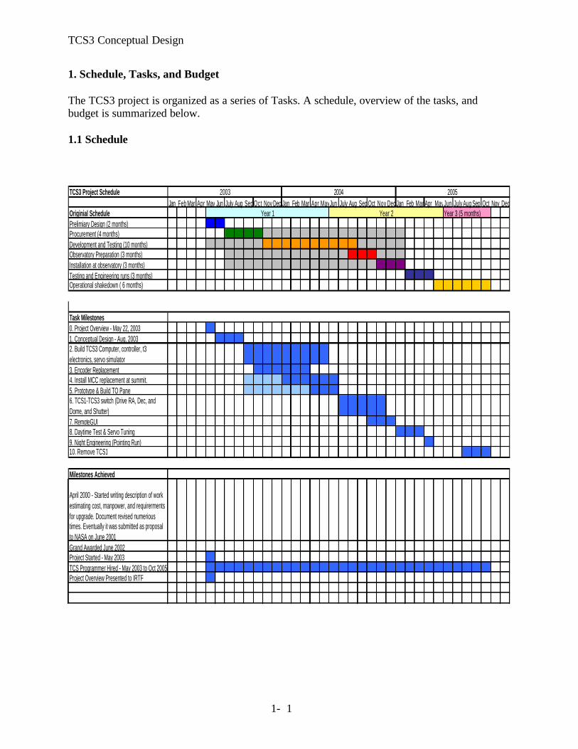
1. Schedule, Tasks, and Budget The TCS3 project is organized as a series of Tasks. A schedule, overview of the tasks, and budget is summarized below. 1.1 Schedule
TCS3 Project Schedule
Jan Feb Mar Apr May Jun July Aug Sep Oct Nov Dec Jan Feb Mar Apr MayJun July Aug Sep Oct Nov Dec Jan Feb Mar Apr MayJun July Aug Sep Oct Nov DecOriginial Schedule Year 3 (5 months)Prelimiary Design (2 months)Procurement (4 months)Development and Testing (10 months)Observatory Preparation (3 months)Installation at observatory (3 months)Testing and Engineering runs (3 months)Operational shakedown ( 6 months)
Task Milestones0. Project Overview - May 22, 20031. Conceptual Design - Aug, 20032. Build TCS3 Computer, controller, t3 electronics, servo simulator3. Encoder Replacement4. Install MCC replacement at summit.5. Prototype & Build TO Panel6. TCS1-TCS3 switch (Drive RA, Dec, and Dome, and Shutter)7. RemoteGUI8. Daytime Test & Servo Tuning9. Night Engineering (Pointing Run)10. Remove TCS1
Milestones Achieved
April 2000 - Started writing description of work estimating cost, manpower, and requirerments for upgrade. Document revised numerious times. Eventually it was submitted as proposal to NASA on June 2001Grand Awarded June 2002Project Started - May 2003TCS Programmer Hired - May 2003 to Oct 2005Project Overview Presented to IRTF
2004 20052003
Year 1 Year 2

TCS3 Conceptual Design
1- 2
1.2 Task List 1 Task: Conceptual Design. Project Man-months : 3 (Jun-Aug 03) Major Milestone : Present Conceptual Design. 2. Task: Build TCS3 computer, servo controller, and servo simulator. Purchase Servo controller (RA, Dec, Dome). Purchase Computer System (2 each, summit & hilo Lab/spare system) Purchase TCS3 Equipment Rack and accessories. Design/Build T3 Electronics interface Implement Servo Simulator (Lab test motors) Develop TO Panel prototype Project Man-months : 9 (Sept 03 – May 04) Major Milestone: Control simulated HA, Dec motors using computer, controller, and T3
electronics.
3. Task: Encoder Replacement.
Install new absolute encoders. Install new incremental encoders. Read the current Dome scanner.
Install computer system at summit. Acquire encoder data into T3 applications. Project Man-months : 6 (Oct 03 – Mar 04) Major Milestone: TCS3 computer system provides HA, Dec, Dome encoding information. 4 Task: Install MCC replacement at summit. Prep TO area for new T3 Displays and TO Panel. (Preliminary task). Purchase Facility IO hardware Develop Facility IO software Install Facility IO at summit. Develop MCC replacement T3 Display 1 & Display 2 GUI. Switch non critical MCC Functions to TCS3 Project Man-months : 6 (Jan – Jun 04 ) Major Milestone: TCS3 used in operations (replacing some non critical MCC functions). 5 Task: Prototype and Build TO Panel Development of TO Panel prototype (Preliminary task sept 03 – mar 04 ) Construct the TO Panels (2 each, summit and development system).

TCS3 Conceptual Design
1- 3
Install TO Panel at summit. Project Man-months : 3 (Apr-Jun 04) Major Milestone: TO Panel completed. 6 Task: TCS1-TCS3 Switching. Install tcs1/tcs3 switch over Hardware. Develop switch over procedures. Switch & test Dome control. Switch & test HA, Dec Axis Control. Install new Shutter JBox and control using MCC Display. Project Man-months: 4 (Jul – Oct 04) Major Milestone: TCS3 Drives RA, Dec, and Dome successfully 7. Task: RemoteGUI Purchase computer for portable T3 interface. Implement RemoteGUI software. Project Man-months : 3 (Oct – Dec 04) Major Milestone: RemoteGUI completed. 8. Task: Daytime Test Schedule Engineering (Daytime) Test: Switch from TCS1 to TCS3. Test HA, Dec, Dome control. Project Man-months : 3 (Jan-Mar 05) Major Milestone: RA, Dec, and Dome servo performance is acceptable. 9. Task: Night Engineering Pointing calibration: Take pointing data, reduce, and input into TCS. Project Man-months : 1 (Apr 05) Major Milestones: TCS3 point ing is calibrated. 10. Task: Remove TCS1 Decommission TCS1 Remove TCS1 equipment. Remove TCS1-TCS3 Switching equipment. Remove TCS1 APE and install new T3 absolute encoders. Remove TCS1 inc encoders, and relocate T3 inc encoders.

TCS3 Conceptual Design
1- 4
Project Man-months : 3 (Aug-Oct 2005) Major Milestones: TCS1 is removed from IRTF. 1.3 Budget
Year 1 Year 2 Year 3
Awarded $300,000.00 $322,000.00 $72,000.00
Computer & Servo Simulator $44,500.00
T3 Electonics $12,000.00
Encoder replacementAbsoute $21,000.00Incremental $21,700.00
MCC Replacement $33,000.00Prep TO areaTO Panel + prototype.
Facility IO $14,000.00 $11,000.00
Software DevelopmentConsulting $24,800.00Applications $5,000.00
TCS1-TCS3 switching $20,000.00
RemoteGUI $6,000.00
Remove TCS1 $15,000.00
14 Supplies $820.00 $1,000.0015 misc $2,000.00 $5,000.00
Personnel16 Software Engineer $104,500.00 1 yr $109,800.00 1 yr $54,900.00 6 mon.17 Electronic Engineer $13,364.80 1 mon. $53,459.20 4 mon18 Electronic Technician $0.00 $106,214.40 1 yr.
19 Facilities/Admministrative Cost $7,782.00 $230.00 $123.00
Total $299,466.80 $317,703.60 $70,023.00

TCS3 Conceptual Design
2- 1
2. TCS3 Overview The overview identifies the major component of the TCS3.
Figure 2.1 provides an overview of TCS3

TCS3 Conceptual Design
2- 2
2.2.1 TCS3 Display1, Display2, and TO Panel The operator’s interface to the T3 systems are Display1, Display2, and the TO panel. Display1 and 2, along with a mouse and keyboard are the console items to the T1 computer. The TO Panel is connected to TCS3 Servo Electronics. 2.2.2 T3 Equipment Rack A 19” equipment rack will be located in the TCS Room, and will house the computer, T3 electronics, Facility IO hardware, and other T3 equipment. 2.2.3 T1 computer The T1 computer is tcs3 computer system. This will be an x86/PCI computer running the Linux Operating System. A servo controller board will be hosted in a PCI slot. 2.2.4 T3 Electronics Custom build electronics will interface the T1 computer and TO Panel to the RA, Dec, and Dome servo system. 2.2.5 Facility IO A general purpose facility IO system will provide the needed analog and digital IO to allow the T1 computer and servo electronics to interface with the facility hardware. 2.2.6 Encoders New absolute and incremental encoders will be installed in parallel with the TCS1 encoders. TCS3 will use the present bar code system for the dome encoding. 2.2.7 Shutter JBox Replacement The Shutter JBox will be replaced to allow the shutter control IO to be routed using an Ethernet IO module.

TCS3 Conceptual Design
3 - 1
3. Computer System and Servo Controller, and Servo Simulator 3.1 TCS3 Computer The TCS3 computer is named “T1”. TCS3 will be made up of 1 computer. This host will be located in the TCS3 Rack in the TCS Room.
Figure 1 – TCS3 computer system with servo simulator
Computer description:
4U 19” Rack mount computer case. Standard x86 PCI motherboard, CD-ROM, Keyboard, mouse, etc. Operate under the Linux OS. Very likely using a Red Hat Linux distribution. Support dual video output for the MCC Display1, and Display2. House a PCI servo control peripheral board to control the HA, and Dec axis. Communicate with facility hardware via IRTF LAN. Two systems will be purchased: “T1” – IRTF TCS3 computer “T1H” – IRLAB development system / spare. A network 100/10 switch will also be located in the TCS3 Rack. All TCS3 Ethernet devices would be connected to the switch. The tcs3 switch will connect to the IRTF LAN. The computer and switch will be housed in a 19” equipment rack. This rack will also provide space for the servo electronics, Facility IO, and other TCS3 equipment. Rack should include fixed or sliding shelf for computer and electronic boxes, and AC power distribution. 2.2 Servo Controller The RA and Dec axis will be controlled using Galili DMC-18x0 Controller board. The DMC-18x0 is a PCI based servo controller. The 4 Axis controller is targeted. Detail information can be found at www.galilmc.com.

TCS3 Conceptual Design
3 - 2
3.3 Servo Simulator The TCS3 project will build and maintain a simple model of the HA and Dec motors and incremental encoders. Absolute encoding not required. We will build a model of each axis, as illustrated in Figure 2.
Figure 2 – Servo Simulator
Amp: +/- 10v input signal. Motor: DC motor Motor rpm: 1200 as/s * 144 / 1296000 as/rev = 0.13 rps. (7.7 seconds to do 1 rev). Motor-Bullgear gearing: 144:1 (same as IRTF motor-bullgear ratio, per Tim Bond 6-24-03) Axis Shaft diameter: TBD Incremental encoder: 100 pulse/as resolution The spare dome scanner will be used to develop/test the dome encoding. A simulator is not need for the dome. 3.4 TCS3 Rack A computer rack will be purchased and assembled. This rack will house the computer, T3 electronics, and Facility IO hardware. Sliding shelf will be used to enable easy access to these electronic boxes. Also include in the rack will be cable mounting hardware, distribution for AC power, and a network switch.
TCS3 Conceptual Design
3 - 3
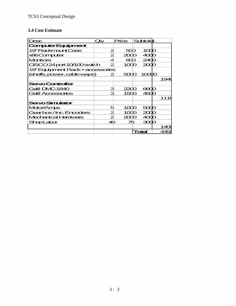
3.4 Cost Estimate
Desc Qty Price SubtotalComputer Equipment19" Rackmount Case 2 500 1000x86 Computer 2 2000 4000Monitors 4 600 2400CISCO 24 port 10/100 switch 2 1000 200019" Equipment Rack + accessories (shelfs, power, cable waps) 2 5000 10000
19400Servo ControllerGalil DMC-1840 3 2200 6600Galil Accessories 3 1500 4500
11100Servo SimulatorMotor/Amps 5 1000 5000Gear box / Inc. Encoders 2 1000 2000Mechanical Hardware 2 2000 4000Shop Labor 40 75 3000
14000Total 44500

T3 Conceptual Design
4 - 1
4. T3 Electronics The T3 electronics refer to the following custom design and build electronics:
1. Axis Interface (HA, Dec) 2. Dome Interface 3. TO Panel Interface
4.1 Axis Interface The axis interface is custom-built electronics that provide the glue logic between the controllers (servo board, TO Panel) and the motor amplifier. There will be two Axis interfaces: HA Axis Interface, and the Dec Axis Interface. The HA and DEC are identical in function which is shown in figure 4.1.
Figure 4.1
4.1.1 General Description The primary job of the AI board is to take a motor command signal from the servo controller board, or from a joystick when in manual mode, and drive the axis by outputting the correct voltages to both motor velocity amplifiers. For the HA and DEC axis, one motor will move the axis, while the other maintains a constant anti-backlash force on the opposite motor, based on the direction. This is achieved by splitting the ±10V signal from the motor controller into two separate signals, a 0 to +10V signal and a -10V to 0 signal which then drives two separate power amplifiers. The second purpose of this board is to gather and distribute the emergency and brake lockout conditions. The safety circuit is shown below in figure 4.2.

T3 Conceptual Design
4 - 2
Figure 4.2
4.1.2 Modes The AI board will support the following modes, which are selected by the operator on the TO panel:
Lockout – Control to the motor amplifiers are disabled. Manual – The control signals for the HA, Dec and Dome are generated from the TO panel’s
joystick interface. Velocity is limited to 400 as/s. Standard – The Standard is the computer-controlled mode. The control for the motor
amplifiers come from computer’s servo controller board. 4.1.3 Limits Each axis has a Slew, Stop, and Brake limit. The AI will react to the limit as follows:
Slew – The velocity output to the motor amps be limited to tracking velocity (400 as/s). Stop – The velocity output to the motor amp will be adjusted to a rate of zero. Brake – The velocity output to the motor amp will be adjusted to a rate of zero and the brakes on the motor will be engaged. Emergency state will be enabled.
The state of the stop limit will be input into the servo controller’s axis limit input. The limit override on the TO panel will disable all 3 limits. 4.1.4 Emergency The Emergency condition occurs when:
1- Brake limit is enabled. 2- Emergency input is enabled. (There are two inputs: TO panel, software input via Facility IO) 3- Over-Current or Over-Temperature error from Amps.
When the emergency condition is active the motor commands to the amplifiers are shut off, and the brakes are engaged. The emergency condition is reset from the TO Panel reset button or facility IO reset input.
4.1.5 General Indicators

T3 Conceptual Design
4 - 3
Output for indicators and monitoring are needed for the following:
Indicator TO Panel Facility IO
Mode (Manual, Standard) Y Y
Limit Override Y Y Emergency Y Y Slew Limits Y Y Stop Limits Y Y Brake Limits Y Y Motor brake on Y Y Motor Current N Y
4.2 Dome Interface The function of this servo interface is similar to the HA and DEC axis with the exception that this controller drives the servo amplifier in both directions by supplying a ±10V signal to the amplifier. The dome interface is shown in figure 4.3.
Figure 4.3
4.3 TO Panel Interface The function of the TO board is to interface to the TO panel components which is shown in Figure 4.4. These components include:
• HA, DEC, and Dome hand paddles. • Emergency stop button with a reset • Key switch with the Lockout, Manual, and Standard positions • Brake control and reset switch, which will also control the switched AC line breaker. • LEDs to indicate: slew, stop, and brake limits, Zenith, emergency, and other conditions

T3 Conceptual Design
4 - 4
Figure 4.4
4.4 Cost Estimate We expect to design 2 boards: 1) HA, Dec, and Dome Axis Interface. 2) TO Panel Interface. We estimated 3 runs for fabrication of the circuit boards: 2 prototypes, and a final production run. Desc Runs Price SubtotalBoard Fabrication
HA, Dec, Dome Axis Interface 3 2000 6000
TO Panel Inteface 3 2000 6000
Total 12000

TCS3 Conceptual Design
5 - 1
5. Encoder Replacement 5.1 Top Level Encoder Requirements. The encoder requirements for the new TCS are as follows: Absolute position resolution: 1.0 arcsec [0.1 arcsec goal] Incremental position resolution: 0.01 arcsec Maximum slew rate: 1200 arcsec/sec on sky [2000 arcsec/sec goal] Maximum slew acceleration: 1200 arcsec/sec2 Environment: -10 to 50 deg C. Humidity:100% Relative Humidity. The old TCS is currently unsupported and the implication of this is that we cannot modify any of the existing encoding hardware, until after the new encoders are commissioned. Unfortunately, the old encoders are installed at the best locations (easy access, stiffness, protected, etc.) on the telescope. 5.2 Current DEC and RA Absolute Encoding.
RA APE DEC APE The current RA absolute position encoder (APE) is located in the North Pier. It is an inductosyn encoder with one half mounted on the yoke, and the other half mounted to the pier. The DEC APE is located in the west arm of the yoke. It is also an induction type encoder (identical to the RA encoder) with one half mounted to the telescope central section, and the other half mounted on the yoke. Both of the current APEs have a resolution of 0.1 arcsec.

TCS3 Conceptual Design
5 - 2
5.3 Current DEC and RA Incremental Encoding.
RA Inc. Encoder Dec Inc. Encoder The current RA incremental encoder is located on the South Pier. It is an optical type encoder (manufacturer – Teledyne Gurley) driven through (approximately) a 180:1 gear ratio friction drive on the back of the bull gear. The current DEC incremental encoder is located in the west arm of the yoke and access is from inside the yoke. It is also an optical type encoder (identical to the RA encoder) also driven through (approximately) a 180:1 gear ratio friction drive on the back of the bull gear. Both of the current incremental encoders have a 3600 line count and associated electronics capable of 40x interpolation for a total of 144 000 pulses/ revolution. After accounting for the gear ratio, this works out to about (3600 x 40 x 180) / (360 x 60 x 60) = 20 pulses per arcsec or 0.05 arcsec resolution. *** Currently, the exact gear ratio is determined through a calibration procedure and works out to be about 19.9041?!? 5.4 TCS3 Absolute Encoding Due to the fact that the current APEs are located in the optimal position for absolute encoding, and the fact that we cannot disturb these encoders until the new TCS3 has completed commissioning, it will be necessary to install temporary absolute encoders. Once the new TCS3 system is commissioned, the encoders will be migrated to the current absolute encoder location. These temporary absolute encoders will be installed on the bull gear through a friction drive. This is a less than ideal situation since they could be subject to slippage or error stack-up at the friction drive. Since the encoder will be driven through the friction drive at an approximate gear ratio of 150:1, it will be necessary for the encoder to yield positional information on its angle as well as information about its number of turns.

TCS3 Conceptual Design
5 - 3
The hardware required for the temporary absolute encoder will be similar (if not identical) to the hardware fabricated for the incremental encoders. A possible candidate for the temporary absolute encoder is the Gurley model A23S Absolute Encoder: Resolution: 8192 words/turn # of resolved turns: 256 gear ratio of 150:1 Yields 1 228 800 counts / rev of the bull gear 0.948 counts / arcsec on the sky approx. 1.0 arcsec resolution The new “final” absolute encoders will optical encoders and will be located in the current APE positions. There are many encoders on the market that will easily meet our requirements. A possible candidate for the final absolute encoder is the Heidenhain RCN226 Absolute Angle Encoder: 67 108 864 position values / rev (26 bits) Yields 51.78 counts / arcsec on the sky 0.0193 arcsec resolution 5.4 TCS3 Incremental Encoding Similar to the case of the absolute encoders, the current incremental encoders are located in the optimal position. The fact that we cannot disturb these encoders until the new TCS3 has completed commissioning will make it necessary to install temporary incremental encoders. Once the new TCS3 system is commissioned, the encoders will be migrated to the current incremental encoder location. These temporary absolute encoders will be installed on the bull gear through a friction drive and identical to the final encoder compliment. Since the encoder will be driven through the friction drive at an approximate gear ratio of 150:1, specialized hardware will have to be fabricated to provide alignment and tensioning. Every effort will be made to make the fabricated hardware for the temporary configuration identical to the hardware required for the final configuration. Since the TCS3 computer may adjust the servo velocity based on positional error measured at 10 Hz, a resolution of 100 Hz (10 x 10 Hz) is highly desired. A possible candidate for the incremental encoder is the Gurley Series 8235S rotary incremental encoder, along with series HR2A high resolution interpolator:

TCS3 Conceptual Design
5 - 4
Line count = 11250 lines/rev Interpolation = 80x Gear ratio of 150:1 Yields 135 000 000 counts/rev of the bull gear
104.167 counts / arcsec on the sky approx. 0.01 arcsec resolution
Also slew rate of 1200 arcsec/sec = 125 000 counts/sec (emerging from electronics) (125 000 counts/sec) / (80) = 1562.5 Hz (emerging from encoder) It would be desirable to find an encoder with higher resolution. This would allow us to work with a smaller gear ratio, mitigating many of the errors/problems that are associated with the friction drive. Several higher resolution encoders from Heidenhain will be investigated. 5.3 Current Dome Encoder
Dome Scanner (side view) Dome scanner (back)
The dome is encoded using a bar code label and a scanner. The scanner outputs is serial (RS-232?). The serial is converted into a parallel graycode using an embedded CPU board. The barcode values range from 1 to 1800, giving the dome a resolution of 0.2 degrees. 5.5 Budget / Manpower The IRTF will provide the mechanical, electrical, and software support via Bond, Keske, and Denault. Initial cost estimates are as follows:

TCS3 Conceptual Design
5 - 5
Absolute Encoders
Items Unit Cost Quanity Sub-TotalGurley A23S 1000 3 3000Misc Materials 1000 2 2000Heidenhain RCN226 1000 3 3000Misc. Materials 500 2 1000Shop Time 75 160 12000
Total 21000Incremental Encoders
Items Unit Cost Quanity Sub-TotalGurley 8235S 950 3 2850Misc Materials 1000 2 2000Gurley HR2A 950 3 2850Misc. Materials 1000 2 2000Shop Time 75 160 12000
Total 21700
Total 42700

TCS3 Conceptual Design
6 - 1
6. MCC replacement 6.1 TCS1 MCC1
Universal time and Local time to be displayed on tcs3 graphics window. All functions can be implemented using software commands. The speaker is used to issue beep for operator feedback.

TCS3 Conceptual Design
6 - 2
6.2 TCS1 MCC2 MCC2 control/display is mostly related to the TCS servo functions (RA, Dec, DOME).
Note from MCC meeting: 1. Safety issue – In the past the computer had shutter control. This was disabled, the shutter can
only be controlled via the MCC. The LED indicated when the shutter has reached its destination. Communication to the shutter is via slip ring. The IRTF has 7 slip ring:
1-3. Power ( 3 Phases) 4. GND 5. Neutral 6. Tone Modem UP. Control signals for lights and shutter. 7. Tone Modem Down. LED switch for shutter position. 8. Signal GND.

TCS3 Conceptual Design
6 - 3
Name Description IO Port Widget TO PanelSidereal time Display display sidreal time Y display valueRight ascension display of RA Y display valueHour Angle display of HA (from APE) Y display value
Declination display of dec (from APE) Y display value
Out-Holdonly use to adjust time in manual mode N
Fast Set " NSlow Set " NTrim +/- " N
Guide - declination - Track - NSThumb wheels to enter rates N
over-speed N
excess error Y displayServo errov value.track N
Guide - Right Ascension -track - WEThumb wheels to enter rates. N
over-speed N
excess error Y DisplayServo errov value.track N
Track & Guide (Red Button)Press button to accept Track/Guide rates. N
Guide Rate ( 60, 30, 15, SW)Selects guide rate - SW input from thumb wheels. N
SHUTTER
Lower Shutter -open/close hold-switch Y up/down hold switchUpper Shutter - open/close hold-switch Y up/down hold switchU.S. Up limit DI DI Y LED displayTouch DI DI Y LED display
L.S. Up LimitDI - present shutter can't reach limit DI Y LED display
LS. Low limit DI DI Y LED displayCrane not stowed DI DI Y LED display
DOME
Dome on offenable/disable computer control Y
Dome Mode
Auto - computer control. Manual used creep buttons. Y choice menu
Manual / Joy switch
Creep = use dome creep speed; Joy = used joy stick to move. Y up/down hold switch
Creep speedIn creep, this level controls the velocity of motors. Y value bar
Dome Joy Stick
In Joy mode, move the dome L/R using the joystick
Telescope Guide: N, S, E, W
offset buttons for LSI. TCS3 may need error N,S,E,W; Also pressing this button disables the slew Y
System ModeNob to indicate who is controling the servo
Manual Under control of MCC NStandard LSI-11/23 control NComp PDP computer - obsolete NSLEWSlew enable Hold to enable slew rates Y up/down hold switchSlew joystick Manual slew Y N-S-E-W buttons
Emergency Stop NobZero velocity to servo motors (RA, Dec, Dome) Y Big Red, push button.
Reset (red button) Enable servo after stop. Y ?? MCC2 functional description table
TCS3 Conceptual Design
6 - 4
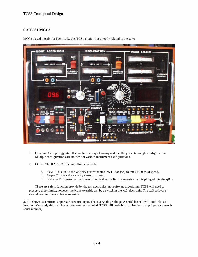
6.3 TCS1 MCC3 MCC3 s used mostly for Facility IO and TCS function not directly related to the servo.
1. Dave and George suggested that we have a way of saving and recalling counterweight configurations.
Multiple configurations are needed for various instrument configurations.
2. Limits. The RA DEC axis has 3 limits controls:
a. Slew – This limits the velocity current from slew (1200 as/s) to track (400 as/s) speed. b. Stop – This sets the velocity current to zero. c. Brakes – This turns on the brakes. The disable this limit, a override card is plugged into the qBus.
These are safety function provide by the tcs electronics. not software algorithms. TCS3 will need to
preserve these limits; however the brake override can be a switch in the tcs3 electronic. The tcs3 software should monitor the tcs3 brake override.
3. Not shown is a mirror support air pressure input. The is a Analog voltage. A serial based DV Monitor box is installed. Currently this data is not monitored or recorded. TCS3 will probably acquire the analog Input (not use the serial monitor).

TCS3 Conceptual Design
6 - 5
Name Description IO Port Widget TO PanelRigh AscensionRA Drive current west Analog In YRA Drive current east Analog In Y
RA Diff switchActual or differential currents. N
DeclinationDec Drive current west Analog In YDec Drive current east Analog In Y
Dec Diff switchActual or differential currents. N
Dome SystemMeter1 Analog In YMeter2 Analog In YMeter3 Analog In YMeter & Turn nobRH Weather data - R. Hum.TEMP Weather data - temp
RH Alarm Shows RH alarm set pointHA enc Temp Displays encoder temp. Not Active
Closed cycle cooler Fail (Blue LED)Indicate if the close cycle cooler is running.
Volt Meter & Turn nobFocus View focus position YCollimate x 2 View collimate position. Y
counterweights x 6View counter weights position Y
MCC Pwr x 4 (+5, +15, -15, +24) View for MCC power N
counterweights (14, 15, 16, 17)View counter weights position Y
Lower Left Button
Brake Toggle & LEDTurns brake on/off. LED on is brake on.
Brake EnableMust press enable to Toggle Brake on/off
Floor lights Dome light -incandesentFl. Dome LTS Dome light - fluorescents
Serv. OverrideAllow limit switch override for daycrew
Mirron SPT on/off
Control mirror support compressor w/ LED indicator. Need to be at zenith to change value.
Mirror CVR Open/close
Open close mirror covers w/ LED indicator. Need to be a zenith to change value.
LIMITS
Zenith LEDLED to indicate Telescope is near zenith.
N, S, E, W LED. 2 Led each. Slew Limit (yel). Stop(red).
Yellow = slow to track speed; Red = Stop TCS movements
Horizon Limits override 1Horizon Limits override 2
Observer's PlatformSlew Limits - UPSlew Limits - WSlew Limits - ETravel Limits - UPTravel Limits - DNTravel Limits - WTravel Limits - E
Lower Right Switches
Coarse EnableSelect either 1-6 or 14-17 counterweight control.
Focus - in / out hold-switchFocus - fast / slow switchCollimate N/S hold-switchCollimate W/E hold-switch
Counterweights
Yoke - H - in/out - 1 or 14 - hold-switch + LED
Yoke - V1 - up/down - 2 hold-switch + LEDYoke - V2 - up/down - 3 hold-switch + LED
Tube - H - up/dn - 4 or 15 - hold-switch +LED
Tube - V1 - up/dn - 5 or 16 - hold-switch + LED
Tube - V2 - up/dn - 6 or 17 - hold-swich + LED
Enable/disable swich + LED Enable / disable counter weight control
Show dome motor currents. Dome has 3
motors, 1 master and 2 slaves
Show drive currents. 2 motor per axis
Show drive currents. 2 motor per axis
2 horizon limit LED and an override
George K. indicated these LED indicators are not
operational. Except that left most LED indicated "Platform Not Stowed"
Focus control for chopping secondary.
Collimation control for chopping secondary
Control switches to move the counter weights. Note
you should only move weight at a time.
MCC3 Functional Description Table

TCS3 Conceptual Design
6 - 6
6.4 Staff Input 6.4.1 David Griep Need to move the Telescope to Zenith (with eyeball accuracy) independent of computer control. Need to move the dome independent of computer control. Need to move the shutter independent of computer control. For new TO Pannel, use a single RA and DEC joy stick. Need Floor light on TO panel for Emergency.

TCS3 Conceptual Design
6 - 7
6.5 TCS3 MCC replacement The MCC3 MCC replacement will visually consist of 2 computer monitors and a TO Panel. Normally the TCS3 computer will be booted up and running at all times. The TCS3 computer will have 2 monitors, in each monitor a GUI window will access to the various MCC functions. The TO Panel will be a hardware panel with controls and indicators to directly control the TCS3 electronics. The tcs1 and tcs3 system will coexist for approximately 1 year. Since space is extremely tight in the TO area, the TCS3 MCC replacements need to be compact. While the tcs1 and tcs3 systems coexist, the TCS3 displays and TO panel may be located just in front of the current MCC panels. 6.6 Prepare TO area for new MCC Displays and TO Panel Some effort will made to improve the TO area to better accommodate the MCC displays and TO panel. Most likely, we will replace the folding table the TO’s use for Max with a larger (real) table, and improving the equipment organization near the current MCC. 6.7 TCS3 Display 1 TCS3 Display 1 will concentrate on items directly related to the RA, Dec, and Dome servos. It provides functions similar to MCC2. Below is an illustration of what this display could look like.
TCS3 Conceptual Design
6 - 8
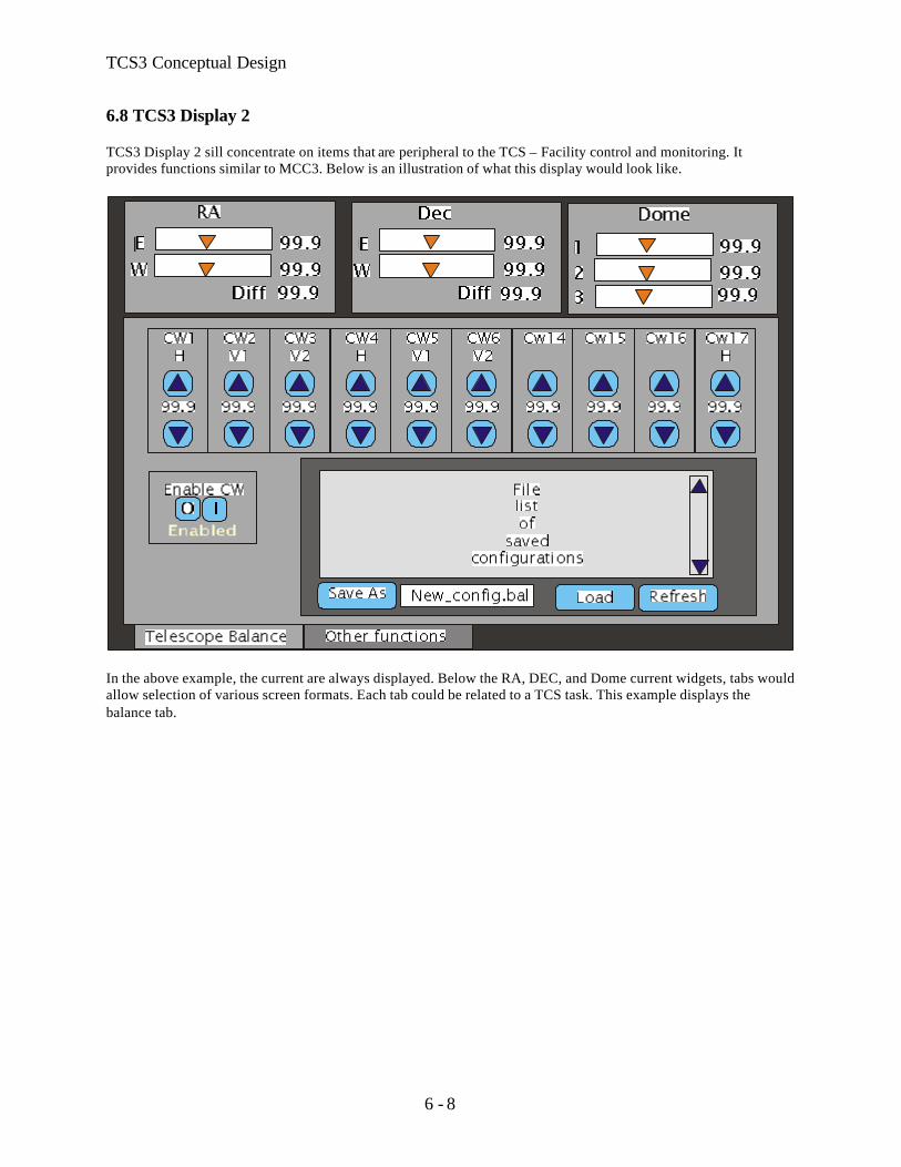
6.8 TCS3 Display 2 TCS3 Display 2 sill concentrate on items that are peripheral to the TCS – Facility control and monitoring. It provides functions similar to MCC3. Below is an illustration of what this display would look like.
In the above example, the current are always displayed. Below the RA, DEC, and Dome current widgets, tabs would allow selection of various screen formats. Each tab could be related to a TCS task. This example displays the balance tab.

TCS3 Conceptual Design
6 - 9
6.9 TO Panel. The TO panel is hardware panel with critical indicators and controls. Ideally it would be about the size of a computer monitor (16”x16”x 10”). It would be physically attached to the TCS3 electronics rack with a cable long enough to be easily positioned and moved around in the TO’s area.
TCS Electronic Modes Lockout – disables any movement to Ra, Dec, Dome motors. Manual – Allow for manual velocity using the velocity joysticks. Standard – Computer control of RA, Dec, Dome velocity is the standard operating mode. Slew Limits Each axis displays the slew and stop limits. Emergency LED on if brake limit are on. Limit Override switch makes TCS electronics to ignore limit inputs (slew, stop, brake). TCS brakes – switch to turn on/off. Must use enable button to accept changes. Emergency Stop – Pressing will disable all velocity and set telescope brakes.

TCS3 Conceptual Design
6 - 10
6.10 Cost Estimate During the Lab development (Sept 03 – Mar 04) a prototype TO panel will be developed. Apr-Jun 2004, the actual MCC2 panels (summit and lab) will be machined.
Desc Qty Price SubtotalEquipment CostCase 3 1000 3000Improve TO area for new MCC equipment 10000
Electronic components (plus spares) 5 2000 10000Shop Labor 120 75 9000misc supplies (cables, etc) 1 1000 1000
033000
0Total 33000

TCS3 Conceptual Design
7- 1
7. Facility IO The Facility IO refers to facility monitoring and control outside of the core TCS control (HA, Dec, Dome servos). We have compiled a list of the current facility IO, and are summarized in the following table.
Type Estimate CountDigital Input 34
Digital Out 40Analog Input 22
Analog Output 0Others serial(1)
Our Facilty IO list is located at: http://irtfweb.ifa.hawaii.edu/~tcs3/systems/tcs3/0306_conceptual_design/07_FacilityIO We have established the following Facility IO requirements:
• 10 Hz update rates • Additional IO can be easily added. • Widely used in Industrial Automation • Wide variety of the IO options. • Ethernet based interface
7.1 Opto22 We have selected the Opto 22 (www.opto22.com) SNAP Ultimate IO to be used for the Facility IO hardware. These devices are similar to products such as Advantech’s ADAM-5000/TCP and SixNet Industrial IO. They all consist of a proprietary bus that can accept a series of IO modules. Control and communication is performed from a control unit. Opto22 had the best balance of available IO module, software support, vendor technical support, and cost. The Opto 22 unit consist a Module Rack ( ~4.5”x15”), controller unit (“Brain”), and up to 16 IO modules. Each IO module can have 4 IO points (64 IO per points per rack).

TCS3 Conceptual Design
7- 2
Figure 1 – SNAP module, with brain and IO modules.
The T3 Electronic Rack will house 3 or 4 Opto22 units that will handle the bulk of the IO requirement. An additional Opto22 unit is required for the new shutter JBox interface. T3 Rack: 3 unit x 64 points = 192 points. Shutter : 1 unit Lab: 1 test units Spare: 1 unit. 7.2 Estimate cost Description Quanity Price Subtotal
Mounting Racks 7 200 1400Power Supply 7 200 1400Brain 7 700 4900Estimated Module cost 96 112 10752
18452
Misc Supplies 2000 1 40004000
Total 22452
Estimate includes 4 TCS3 unit, 1 lab units, 1 dome unit, and 1 provisional.

TCS3 Conceptual Design
8 - 1
8. Software Design 8.1. Notes on computer variables, their ranges and precision. These values were obtained using solaris 2.6 on SPARC Iii, gcc version 2.7.2. Type
Bits
Signed Range
Unsigned Range
Char 8 -128 to 127 0 to 255
Short 16 -32768 to 32767 0 to 65535
Long 32 -2147483648L 2147483647L
0 4294967295U
Long Long 64 -9223372036854775808L 9223372036854775807L
0 18446744073709551615UL
Float 32 23 significant bits in mantissa, 6.92369 significant digits in decimal number. Double 64 52 significant bits in mantissa, 15.6536 significant digits in decimal number. Positions can be stored in double as radians. 360 degrees = 2.683185307 radians. At 15 significant digits, the resolution is better that 5 nanoarcseconds. Time can be stored in double as Modified Julian days. MJD has 5 decimal digits, leaving 10 fractional significant digits. This gives accuracy to better that 10 microseconds. For the TCS to 1ms accuracy is sufficient. 8.2. Notes on Limits. Base Position:
A S RadiansR A 0 to 24 hrs 0 to 2*PIDec -90 to 90 deg -PI/2 to PI/2Base Rate limitsBase increment l imits
Offset
A S RadiansIndividual Offset LimitsIndividual Rate LimitsTotal Offset LimitTotal Rate Limits
Servo Position Limits:
HA Axis Dec Axis
hh m m sec Radians ArcSec deg m m sec Radians ArcSec
Servo Limit min -5 4 47.00 -1.329868168 -274305.00 -59 0 0.00 -1.029744259 -212400.00
Servo Limit Max 5 4 47.00 1.329868168 274305.00 69 56 0.00 1.220566924 251760.002.6597363 548610 2.25031118 464160.00
TCS3 Conceptual Design
8 - 2
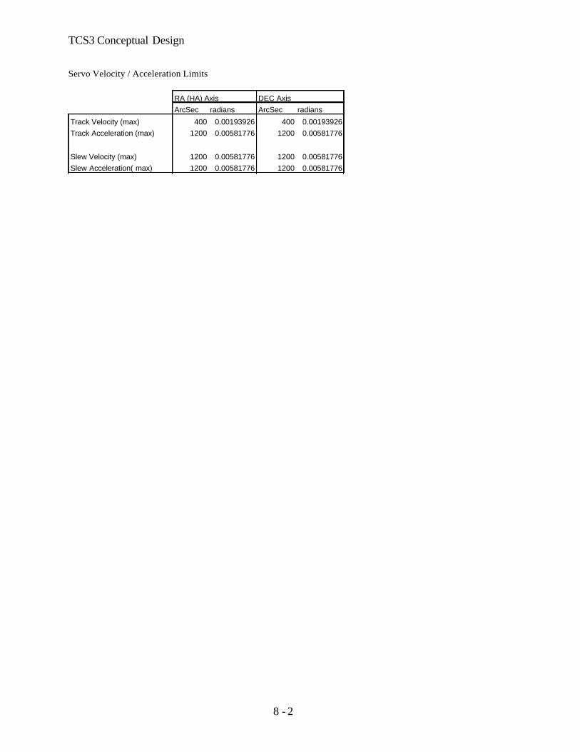
Servo Velocity / Acceleration Limits
RA (HA) Axis DEC AxisArcSec radians ArcSec radians
Track Velocity (max) 400 0.00193926 400 0.00193926Track Acceleration (max) 1200 0.00581776 1200 0.00581776
Slew Velocity (max) 1200 0.00581776 1200 0.00581776Slew Acceleration( max) 1200 0.00581776 1200 0.00581776
TCS3 Conceptual Design
8 - 3
8.3. General Software Guidelines
• Development and deployment on a Linux OS/x86 system. • All application written in C – minimize the use of other computer languages. • Astronomy calculations algorithms are done using slalib or TCSpk. • Pointing correction to be based on the TPOINT software application. • GUI is written using GTK+ • Use the POSIX API for system and clib calls, shared memory, message queues, scheduling and processing
control. • Berkeley Socket API and remote procedures call (RPC) are used for network libraries.
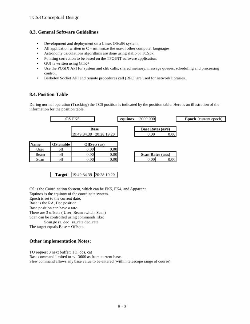
8.4. Position Table During normal operation (Tracking) the TCS position is indicated by the position table. Here is an illustration of the information for the position table.
CS FK5 equinox 2000.000 Epoch (current epoch)
19:49:34.39 20:28:19.20 0.00 0.00
Name OS.enableUser off 0.00 0.00Beam off 0.00 0.00Scan off 0.00 0.00 0.00 0.00
Target 19:49:34.39 20:28:19.20
Base Base Rates (as/s)
OffSets (as)
Scan Rates (as/s)
CS is the Coordination System, which can be FK5, FK4, and Apparent. Equinox is the equinox of the coordinate system. Epoch is set to the current date. Base is the RA, Dec position. Base position can have a rate. There are 3 offsets ( User, Beam switch, Scan) Scan can be controlled using commands like: Scan.go ra, dec ra_rate dec_rate The target equals Base + Offsets. Other implementation Notes: TO request 3 next buffer: TO, obs, cat Base command limited to +/- 3600 as from current base. Slew command allows any base value to be entered (within telescope range of course).

TCS3 Conceptual Design
8 - 4
8.5. Mean to Mount Calculations This table illustrates the coordinate transformations from user inputs to mount position.

TCS3 Conceptual Design
8 - 5
8.6. Pointing Correction The pointing correction will be based on TPOINT. Information on TPOINT can be found at www.tpsoft.demon.co.uk The following TPOINT terms will be supported. IH - Index Error in Hour Angle ID - Index Error in Declination NP - HA/Dec Non-perpendicularity CH - East-West Collimation Error ME - Polar Axis Misalignment in Elevation MA - Polar Axis Misalignment in Azimuth FO - Fork Flexure HA - Centering Error, Sine Component DCES - Dec Centering Error, Sine Component TF - Tube flexure (sine) TX - Tube Flexure (tangent) 8.7. RA, DEC Servo Modes - The following RA, Dec servo mode will be implemented.
Idle – No active servo control being performed.
Time information is calculated. Velocity of all motors (ra, dec, dome) will be set to 0. Encoder are read and a reverse mount->Target positions are calculated. All rates & Offset parameters are set to 0.
Track – Track based on the Target position from Position Table.
Time information is calculated. Rates are applied to base and offsets. Coordinates transformation Target RA,Dec -> mount are calculated. Servo task will command motors to this position.
Slew – High speed move to Target position from Position Table.
Same as track, but increase velocity limits from 400 ac/s to 1200 as/s.
Motor Position – Point to point motor using axis coordinates.
Time information is calculated. Encoder determines telescope position Reverse transformation mount->Target is calculated. Motor velocity can be specified.
Motor Velocity – Jog type motor command.
Time information is calculated. Encoder determines telescope position. Reverse transformation mount->Target is calculated. Motor velocity can be specified.
8.8 Dome servo modes. The following Dome servo mode will be implemented.

TCS3 Conceptual Design
8 - 6
Manual - Operator can increment or decrement dome position. Auto - Dome will track the Azimuth of the TCS, and auto position the dome.
8.9 Shutter Shutter control / feedback will be the same are the current system. 8.10 Facility communications Communication to TCS3 will be done using TCP/IP and/or UDP. Communication based on a ‘serial line interface’ method - text command and replies using a simple command language. A socket based terminal IO should is one option to connect to the tcs3. This is a stream based network socket. The full command set will be supported over the TCP/IP link. Multiple telnet sessions into the TCS will be supported. An RPC daemon will support UDP type commands/queries. This will provide a limited command set. Very verbose and interactive commands will be disabled. However, this connect-less protocol will support a higher rate of exchange and much quicker individual performance.

TCS3 Conceptual Design
8 - 7
8.10 TCS3 Application Block Diagram
IC – T3 software application. Creates system resources (ie: shared memory) and start all T3 sub-processes. Timer – control task to schedule time critical task. Vtcs – Virtual TCS task does astronomical calculations. Calculation loop is 20 Hz. Rtcs – Real TCS task is responsible for positioning the RA, Dec axis through the servo controller board. A 20 Hz task. ttd – T3 Telnet Daemon allows sock connection to T3 command interface. Multiple socket connections allowed. t3.rpc – Alternate network interface to t3 commands using RPC. Pfast – A fast periodic task – general purpose fast execute loop (1 to 10Hz). Pslow- a slow periodic task – general purpose execute loop (>1 Hz). Fio – Facility IO tasks to monitor and control the facility IO hardware. A 10 Hz update loop. T3D1, T3D2 – X based display for MCC-like displays. TO GUI – The TO GUI is a X based display application. This is what the TO will run on Max. T3 Remote GUI – A simpler GUI for remote observing and as a portable TCS interface.

TCS3 Conceptual Design
9- 1
9. TCS1-TCS3 Switching We need to switch between TCS1 & TCS3 to driver the RA, Dec, and Dome servo systems. The switch back fairly quickly and easily. This will enable daytime test runs and night time engineering with using TCS3, while keeping TCS1 operational. The new encoders and the replacement MCC (using computer display) should be operational by this point in the project. This should minimize the number of signals to be switched. This task should be fairly straight forward, not posing any great technical challenges. At the required time we will survey the signals to be switched, purchase or build the necessary hardware, and install them. 9.1 Shutter Controller The JBox for the shutter IO interface needs to be changed. The current JBox communicates over the slip ring using the tone modem equipment. We wish to decommission the tone modem equipment. The new JBox will be connected directly to a Opto22 device. This opto22 will connect to the network using the Shutter hub installed as part of the IQUP project. This Hub is connected to the IRTF Lab using X10 device to traverse the slip rings. 9.2 Schedule and Budget Tcs1-tcs3 switching is scheduled for Jul-Oct 04 (4 month). The achieved milestone is to have the T3 system drive the HA, Dec, and Dome successfully. The shutter control will be transferred to the new MCC. We allocated $20K for the tcs1-tcs3 switching and shutter control hardware.

TCS3 Conceptual Design
10 - 1
10. T3 Remote GUI The T3 Remote GUI is a scaled down graphical interface for the TCS to be used by:
• Summit Observers • Remote Observers • Day Crew (or by anyone running the TCS away from the TO area).
This application will displace the need for a custom hardware panel. Advantage of using a software GUI vs. Hardware panel are:
• No custom Hardware to purchase and maintain • No custom software (embedded OS, tool, application) needed. • Additional expertise required for customized solution is not needed. • Software GUI is easily to modify and maintain. • Application runs on a generic portable computer.
The close example to our RemoteGUI would be the tcs1_status application current being used at the IRTF. The T3 RemoteGUI would support additional function, quicker response due to the improved network communication infrastructure provide by the TCS3
Figure 10.1 – Current tcs1_status application
10.1 Cost Estimate 2 laptop X $3K = $6K

TCS3 Conceptual Design
11 - 1
11. Remove TCS1 Once the T3 is accepted as the operational TCS, TCS1 can be removed. The following major tasked are identified:
• Remove TCS1 Equipment including MCC panel. • Remove TCS1-TCS3 switching equipment.
• Implement final configuration of the encoders.
$15 K has been reserved in the budget for any final task associated with removing the old TCS.


