MEITRACK GPRS Protocol · MEITRACK GPRS Protocol MEITRACK GPRS Protocol
Upload
cscjournalsCategory
view
242download
1
A.K. Othman, M. Zakaria, K. Ab. Hamid
International Journal of Engineering, Volume (2) : Issue (1) 42
TCP Performance Measurement in GPRS Link Adaptation Process
Al-Khalid Othman [email protected] Faculty of Engineering Universiti Malaysia Sarawak Kota Samarahan, 94300, Sarawak, Malaysia Muzalina Zakaria [email protected] Faculty of Engineering Universiti Malaysia Sarawak Kota Samarahan, 94300, Sarawak, Malaysia
Khairuddin Ab. Hamid [email protected] Chancellery Universiti Malaysia Sarawak Kota Samarahan, 94300, Sarawak, Malaysia
Abstract
This paper presents the results of measured TCP performance in the LA process during the deployment of GPRS CS1 and CS2 coding schemes and after the activation of two more coding schemes, CS3 and CS4. The measurements are done under various network scenarios based on users’ physical locations in one of Malaysia’s commercially deployed live GPRS networks. End-to-end FTP file transfer application is used for the assessment together with tracing at the GPRS air interface. The results show that TCP works well in the LA process and can adapt to the frequent switching between the coding schemes without any problem. The average throughput is increased by 23% for urban areas owing to the activation of higher coding schemes and aided by TCP tuning. It is also shown that bad radio condition is the main factor affecting throughput. TCP performance is seen to be constant in all scenarios and it can cope with GPRS mobility and bad radio condition, although at the expense of reduced throughput. Keywords: GPRS, TCP, Performance, Link Adaptation, Coding Scheme, Network Scenarios.
1. INTRODUCTION
General Packet Radio Service (GPRS) [1], [2] is an extension of Global System for Mobile communications (GSM) network. It offers packet-switched data transmission over the GSM air interface with efficient radio protocols to cover for erroneous data packets. GPRS provides ‘always connected, always online’ data services such as Internet applications to mobile users with data rate between 36.2kbps to 85.6kbps for four time slots allocation. Internet applications such as web surfing, e-mail and file transfer rely on Transmission Control Protocol (TCP) [3] as a reliable transport for data transfers. It is a connection-oriented, packet-
A.K. Othman, M. Zakaria, K. Ab. Hamid
International Journal of Engineering, Volume (2) : Issue (1) 43
switched transport method that delivers data in small segments or packets. TCP ensures ordered, error-free data delivery with its sequence numbering and acknowledgment systems together with retransmission of loss packets and checksum evaluation. Additionally, it provides data flow control through its congestion control mechanisms.
TCP is originally designed for data transfers across wired, fixed networks [4]. It anticipates transmission problems that are typical with wired networks behaviors. With the implementation of GPRS, TCP traverses the wireless mobile network which is a different environment from the wired network. The varying radio conditions expose data transfers over the wireless GPRS network to transmission errors. Accordingly, four GPRS coding schemes, CS1 to CS4, are defined and employed to protect data from these errors [5]. Switching between the coding schemes is dynamically done through a process called link adaptation (LA) [6]. The LA process may cause some impacts on the performance of Internet applications over live GPRS network. Moreover, due to the mobility factor, GPRS users are subjected to several network scenarios based on their physical locations. For example in urban areas, common locations for GPRS users are inside buildings, or outdoors in moving vehicles. The performance of Internet applications as perceived by users may vary depending on these scenarios. These issues have not been specifically addressed in the previous studies conducted on TCP performance in GPRS network [7], [8], [9]. There is a necessity to conduct measurements at the TCP layer to see the effects of the LA process on TCP performance. What are the TCP behaviors in different coding schemes? What are the factors that affect TCP performance? Are higher coding schemes giving a better TCP performance? Is it really beneficial and worthwhile to upgrade the coding schemes? Furthermore, all these are to be observed in a live network where there are many other factors beyond control like time slots availability, signal quality, users’ mobility, and test environments that will give impact to the overall TCP performance, directly or indirectly. Therefore, to have more conclusive results, TCP performance measurement in GPRS LA process under different network scenarios ought to be taken under consideration.
This paper evaluates and compares the TCP performance throughout the LA process in one of the commercially deployed GPRS networks based on the initial coding schemes employment CS1 and CS2, and after the activation of higher coding schemes, CS3 and CS4. This is accomplished by incorporating TCP packet captures in GPRS drive-test measurements carried out in different scenarios based on GPRS users’ typical locations in urban environment. TCP tuning is done as well to optimize the performance.
The TCP throughput and the TCP behaviors observed are examined together with GPRS tracing at the air interface. It is shown that TCP can adapt well to the LA process without any problem. The throughput improvement is moderate at best and is mainly governed by the current coding scheme used. TCP is seen to be affected by long delays encountered during data transfers that trigger its slow start process and further reduce the already low throughput achieved. The results obtained are only relevant to the particular GPRS network being assessed, thus may not apply to all GPRS networks in general.
The rest of the paper is organized as follows: section 2 outlines briefly the GPRS LA process together with GPRS parameters setup as implemented in this commercial network. Section 3 describes network scenarios selected for the measurements. Section 4 gives the overview of the TCP tuning done. In section 5, measurement set up is presented. The results obtained are discussed in Section 6. Finally, the conclusions of the study are given in Section 7.
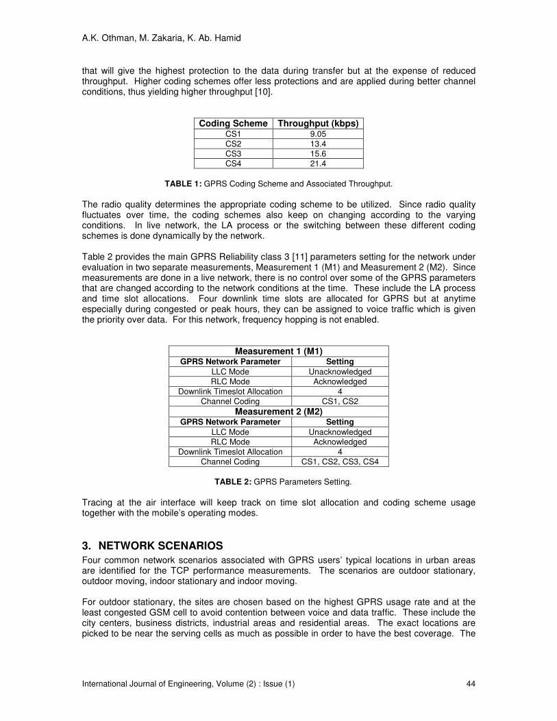
2. GPRS LA PROCESS AND PARAMETERS SETUP
Table 1 gives the GPRS coding scheme with the associated throughput per time slot. In bad channel condition with high anticipated transmission errors, a stringent coding scheme is used
A.K. Othman, M. Zakaria, K. Ab. Hamid
International Journal of Engineering, Volume (2) : Issue (1) 44
that will give the highest protection to the data during transfer but at the expense of reduced throughput. Higher coding schemes offer less protections and are applied during better channel conditions, thus yielding higher throughput [10].
Coding Scheme Throughput (kbps) CS1 9.05
CS2 13.4
CS3 15.6
CS4 21.4
TABLE 1: GPRS Coding Scheme and Associated Throughput.
The radio quality determines the appropriate coding scheme to be utilized. Since radio quality fluctuates over time, the coding schemes also keep on changing according to the varying conditions. In live network, the LA process or the switching between these different coding schemes is done dynamically by the network.
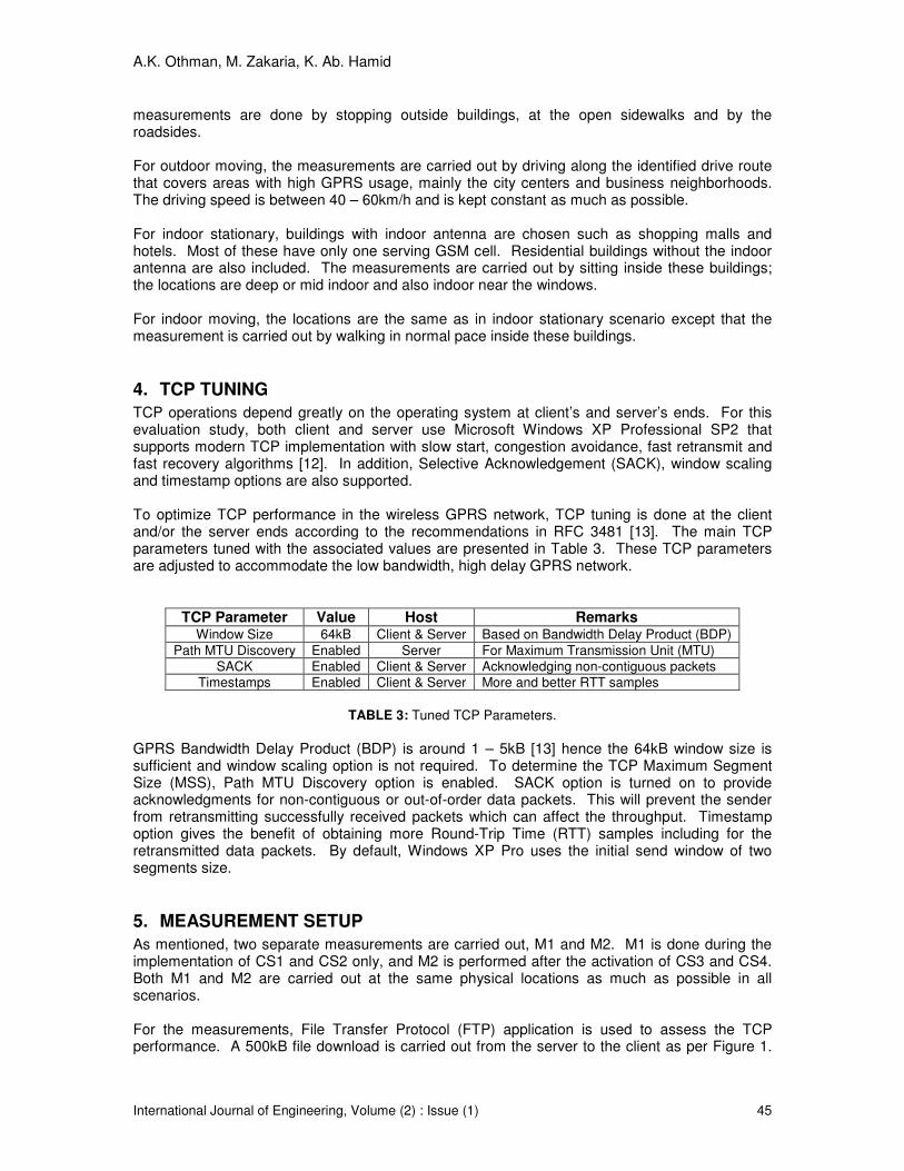
Table 2 provides the main GPRS Reliability class 3 [11] parameters setting for the network under evaluation in two separate measurements, Measurement 1 (M1) and Measurement 2 (M2). Since measurements are done in a live network, there is no control over some of the GPRS parameters that are changed according to the network conditions at the time. These include the LA process and time slot allocations. Four downlink time slots are allocated for GPRS but at anytime especially during congested or peak hours, they can be assigned to voice traffic which is given the priority over data. For this network, frequency hopping is not enabled.
Measurement 1 (M1) GPRS Network Parameter Setting
LLC Mode Unacknowledged
RLC Mode Acknowledged
Downlink Timeslot Allocation 4
Channel Coding CS1, CS2
Measurement 2 (M2) GPRS Network Parameter Setting
LLC Mode Unacknowledged
RLC Mode Acknowledged
Downlink Timeslot Allocation 4
Channel Coding CS1, CS2, CS3, CS4
TABLE 2: GPRS Parameters Setting.
Tracing at the air interface will keep track on time slot allocation and coding scheme usage together with the mobile’s operating modes.
3. NETWORK SCENARIOS
Four common network scenarios associated with GPRS users’ typical locations in urban areas are identified for the TCP performance measurements. The scenarios are outdoor stationary, outdoor moving, indoor stationary and indoor moving.
For outdoor stationary, the sites are chosen based on the highest GPRS usage rate and at the least congested GSM cell to avoid contention between voice and data traffic. These include the city centers, business districts, industrial areas and residential areas. The exact locations are picked to be near the serving cells as much as possible in order to have the best coverage. The
A.K. Othman, M. Zakaria, K. Ab. Hamid
International Journal of Engineering, Volume (2) : Issue (1) 45
measurements are done by stopping outside buildings, at the open sidewalks and by the roadsides. For outdoor moving, the measurements are carried out by driving along the identified drive route that covers areas with high GPRS usage, mainly the city centers and business neighborhoods. The driving speed is between 40 – 60km/h and is kept constant as much as possible. For indoor stationary, buildings with indoor antenna are chosen such as shopping malls and hotels. Most of these have only one serving GSM cell. Residential buildings without the indoor antenna are also included. The measurements are carried out by sitting inside these buildings; the locations are deep or mid indoor and also indoor near the windows. For indoor moving, the locations are the same as in indoor stationary scenario except that the measurement is carried out by walking in normal pace inside these buildings.
4. TCP TUNING
TCP operations depend greatly on the operating system at client’s and server’s ends. For this evaluation study, both client and server use Microsoft Windows XP Professional SP2 that supports modern TCP implementation with slow start, congestion avoidance, fast retransmit and fast recovery algorithms [12]. In addition, Selective Acknowledgement (SACK), window scaling and timestamp options are also supported. To optimize TCP performance in the wireless GPRS network, TCP tuning is done at the client and/or the server ends according to the recommendations in RFC 3481 [13]. The main TCP parameters tuned with the associated values are presented in Table 3. These TCP parameters are adjusted to accommodate the low bandwidth, high delay GPRS network.
TCP Parameter Value Host Remarks Window Size 64kB Client & Server Based on Bandwidth Delay Product (BDP)
Path MTU Discovery Enabled Server For Maximum Transmission Unit (MTU)
SACK Enabled Client & Server Acknowledging non-contiguous packets
Timestamps Enabled Client & Server More and better RTT samples
TABLE 3: Tuned TCP Parameters.
GPRS Bandwidth Delay Product (BDP) is around 1 – 5kB [13] hence the 64kB window size is sufficient and window scaling option is not required. To determine the TCP Maximum Segment Size (MSS), Path MTU Discovery option is enabled. SACK option is turned on to provide acknowledgments for non-contiguous or out-of-order data packets. This will prevent the sender from retransmitting successfully received packets which can affect the throughput. Timestamp option gives the benefit of obtaining more Round-Trip Time (RTT) samples including for the retransmitted data packets. By default, Windows XP Pro uses the initial send window of two segments size.
5. MEASUREMENT SETUP
As mentioned, two separate measurements are carried out, M1 and M2. M1 is done during the implementation of CS1 and CS2 only, and M2 is performed after the activation of CS3 and CS4. Both M1 and M2 are carried out at the same physical locations as much as possible in all scenarios.
For the measurements, File Transfer Protocol (FTP) application is used to assess the TCP performance. A 500kB file download is carried out from the server to the client as per Figure 1.

A.K. Othman, M. Zakaria, K. Ab. Hamid
International Journal of Engineering, Volume (2) : Issue (1) 46
The bulk data download using FTP can give insights to TCP steady-state behaviors. Hence, only FTP data connection is considered to compute the performance metrics in the server-to-client direction that corresponds to GPRS downlink direction. For each defined scenario, 32 to 60 repetitive file transfers are performed. At both server and client ends, Wireshark [14] is used to capture the TCP packets exchanged. The captures are then analyzed using tcptrace [15]. Concurrently, TEMS Investigation [16] is run at the client side to capture on GPRS air interface using a class 10 (4 Downlink + 2 Uplink) mobile phone. This supports four time slots for downlink data transfer.
FIGURE 1: Measurement Setup.
6. MEASUREMENT RESULTS
6.1 TCP Throughput and Packet Loss For both M1 and M2, the throughput results are described by the average, max (maximum) and min (minimum) of the total throughput for the whole data transfers in all scenarios and the total throughput for all data transfers in each scenario. Figure 2 presents the comparison on the client’s overall throughput obtained from both measurements. The highest CS data rate is according to CS2 and CS4 with four time slots allocations. The average throughput is computed based on transmitted data bytes over transfer time excluding headers.
A.K. Othman, M. Zakaria, K. Ab. Hamid
International Journal of Engineering, Volume (2) : Issue (1) 47
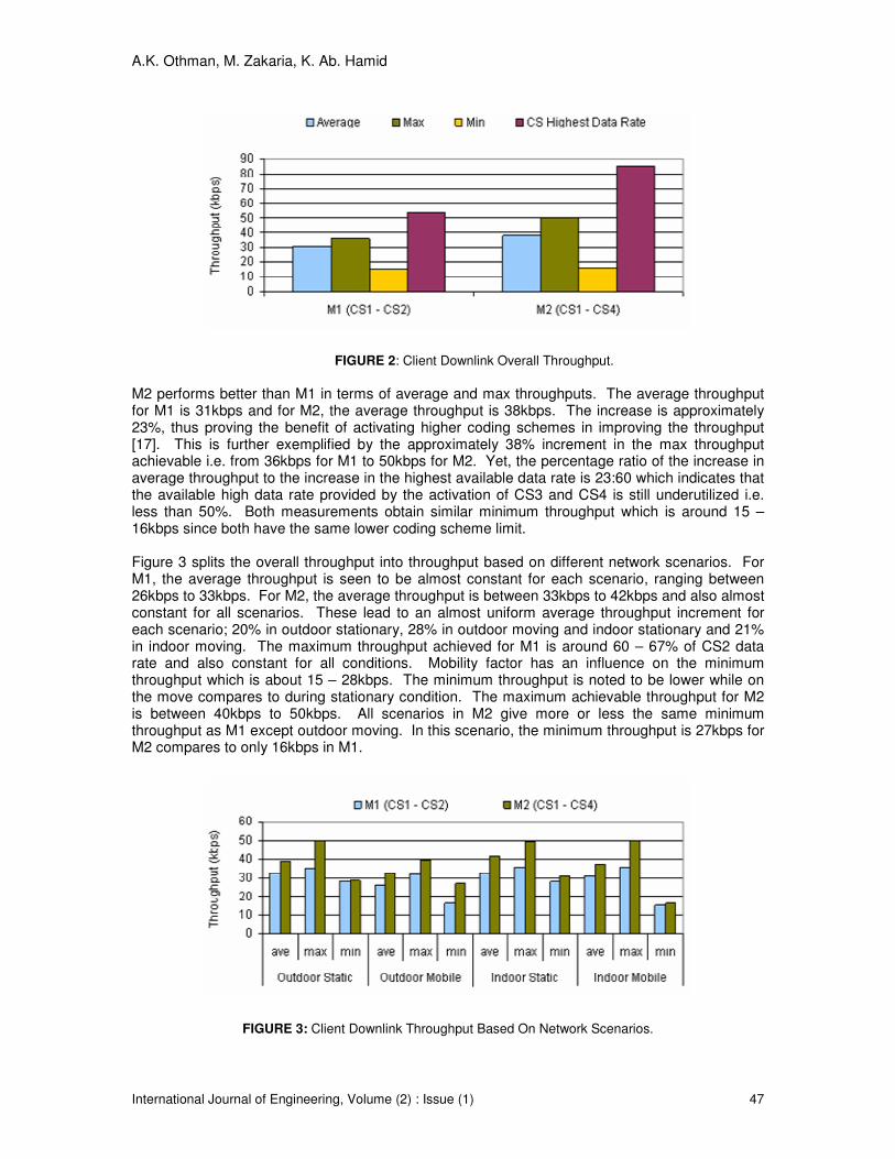
FIGURE 2: Client Downlink Overall Throughput.
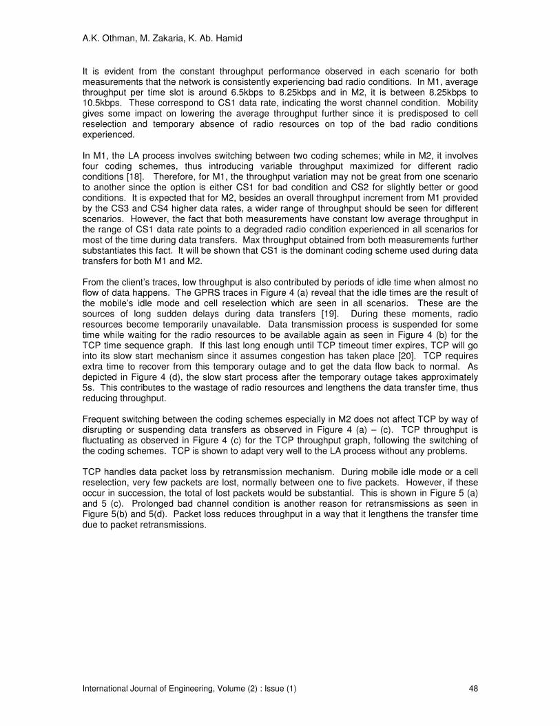
M2 performs better than M1 in terms of average and max throughputs. The average throughput for M1 is 31kbps and for M2, the average throughput is 38kbps. The increase is approximately 23%, thus proving the benefit of activating higher coding schemes in improving the throughput [17]. This is further exemplified by the approximately 38% increment in the max throughput achievable i.e. from 36kbps for M1 to 50kbps for M2. Yet, the percentage ratio of the increase in average throughput to the increase in the highest available data rate is 23:60 which indicates that the available high data rate provided by the activation of CS3 and CS4 is still underutilized i.e. less than 50%. Both measurements obtain similar minimum throughput which is around 15 – 16kbps since both have the same lower coding scheme limit. Figure 3 splits the overall throughput into throughput based on different network scenarios. For M1, the average throughput is seen to be almost constant for each scenario, ranging between 26kbps to 33kbps. For M2, the average throughput is between 33kbps to 42kbps and also almost constant for all scenarios. These lead to an almost uniform average throughput increment for each scenario; 20% in outdoor stationary, 28% in outdoor moving and indoor stationary and 21% in indoor moving. The maximum throughput achieved for M1 is around 60 – 67% of CS2 data rate and also constant for all conditions. Mobility factor has an influence on the minimum throughput which is about 15 – 28kbps. The minimum throughput is noted to be lower while on the move compares to during stationary condition. The maximum achievable throughput for M2 is between 40kbps to 50kbps. All scenarios in M2 give more or less the same minimum throughput as M1 except outdoor moving. In this scenario, the minimum throughput is 27kbps for M2 compares to only 16kbps in M1.
FIGURE 3: Client Downlink Throughput Based On Network Scenarios.
A.K. Othman, M. Zakaria, K. Ab. Hamid
International Journal of Engineering, Volume (2) : Issue (1) 48
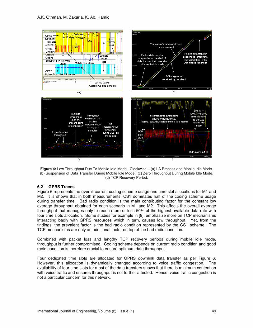
It is evident from the constant throughput performance observed in each scenario for both measurements that the network is consistently experiencing bad radio conditions. In M1, average throughput per time slot is around 6.5kbps to 8.25kbps and in M2, it is between 8.25kbps to 10.5kbps. These correspond to CS1 data rate, indicating the worst channel condition. Mobility gives some impact on lowering the average throughput further since it is predisposed to cell reselection and temporary absence of radio resources on top of the bad radio conditions experienced. In M1, the LA process involves switching between two coding schemes; while in M2, it involves four coding schemes, thus introducing variable throughput maximized for different radio conditions [18]. Therefore, for M1, the throughput variation may not be great from one scenario to another since the option is either CS1 for bad condition and CS2 for slightly better or good conditions. It is expected that for M2, besides an overall throughput increment from M1 provided by the CS3 and CS4 higher data rates, a wider range of throughput should be seen for different scenarios. However, the fact that both measurements have constant low average throughput in the range of CS1 data rate points to a degraded radio condition experienced in all scenarios for most of the time during data transfers. Max throughput obtained from both measurements further substantiates this fact. It will be shown that CS1 is the dominant coding scheme used during data transfers for both M1 and M2. From the client’s traces, low throughput is also contributed by periods of idle time when almost no flow of data happens. The GPRS traces in Figure 4 (a) reveal that the idle times are the result of the mobile’s idle mode and cell reselection which are seen in all scenarios. These are the sources of long sudden delays during data transfers [19]. During these moments, radio resources become temporarily unavailable. Data transmission process is suspended for some time while waiting for the radio resources to be available again as seen in Figure 4 (b) for the TCP time sequence graph. If this last long enough until TCP timeout timer expires, TCP will go into its slow start mechanism since it assumes congestion has taken place [20]. TCP requires extra time to recover from this temporary outage and to get the data flow back to normal. As depicted in Figure 4 (d), the slow start process after the temporary outage takes approximately 5s. This contributes to the wastage of radio resources and lengthens the data transfer time, thus reducing throughput. Frequent switching between the coding schemes especially in M2 does not affect TCP by way of disrupting or suspending data transfers as observed in Figure 4 (a) – (c). TCP throughput is fluctuating as observed in Figure 4 (c) for the TCP throughput graph, following the switching of the coding schemes. TCP is shown to adapt very well to the LA process without any problems. TCP handles data packet loss by retransmission mechanism. During mobile idle mode or a cell reselection, very few packets are lost, normally between one to five packets. However, if these occur in succession, the total of lost packets would be substantial. This is shown in Figure 5 (a) and 5 (c). Prolonged bad channel condition is another reason for retransmissions as seen in Figure 5(b) and 5(d). Packet loss reduces throughput in a way that it lengthens the transfer time due to packet retransmissions.
A.K. Othman, M. Zakaria, K. Ab. Hamid
International Journal of Engineering, Volume (2) : Issue (1) 49
Figure 4: Low Throughput Due To Mobile Idle Mode. Clockwise – (a) LA Process and Mobile Idle Mode. (b) Suspension of Data Transfer During Mobile Idle Mode. (c) Zero Throughput During Mobile Idle Mode.
(d) TCP Recovery Period.
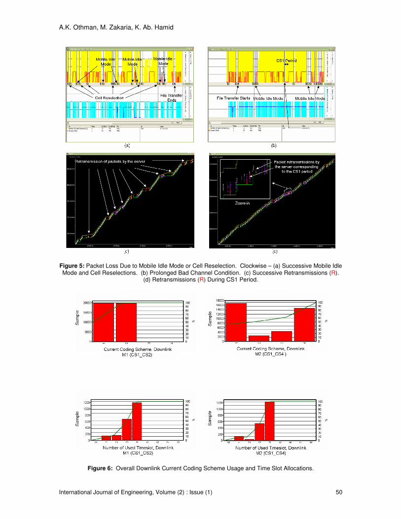
6.2 GPRS Traces Figure 6 represents the overall current coding scheme usage and time slot allocations for M1 and M2. It is shown that in both measurements, CS1 dominates half of the coding scheme usage during transfer time. Bad radio condition is the main contributing factor for the constant low average throughput obtained for each scenario in M1 and M2. This affects the overall average throughput that manages only to reach more or less 50% of the highest available data rate with four time slots allocation. Some studies for example in [8], emphasize more on TCP mechanisms interacting badly with GPRS resources which in turn, causes low throughput. Yet, from the findings, the prevalent factor is the bad radio condition represented by the CS1 scheme. The TCP mechanisms are only an additional factor on top of the bad radio condition. Combined with packet loss and lengthy TCP recovery periods during mobile idle mode, throughput is further compromised. Coding scheme depends on current radio condition and good radio condition is therefore crucial to ensure optimum data throughput. Four dedicated time slots are allocated for GPRS downlink data transfer as per Figure 6. However, this allocation is dynamically changed according to voice traffic congestion. The availability of four time slots for most of the data transfers shows that there is minimum contention with voice traffic and ensures throughput is not further affected. Hence, voice traffic congestion is not a particular concern for this network.
A.K. Othman, M. Zakaria, K. Ab. Hamid
International Journal of Engineering, Volume (2) : Issue (1) 50
Figure 5: Packet Loss Due to Mobile Idle Mode or Cell Reselection. Clockwise – (a) Successive Mobile Idle Mode and Cell Reselections. (b) Prolonged Bad Channel Condition. (c) Successive Retransmissions (R).
(d) Retransmissions (R) During CS1 Period.
Figure 6: Overall Downlink Current Coding Scheme Usage and Time Slot Allocations.
A.K. Othman, M. Zakaria, K. Ab. Hamid
International Journal of Engineering, Volume (2) : Issue (1) 51
7. CONCLUSIONS
TCP adapts well in the LA process and can cope with the frequent switching between the coding schemes without any problem. The activation of higher coding schemes does not increase TCP performance much because of the consistently bad radio conditions experienced during data transfers for all scenarios. Unless radio condition is improved, the benefit of activating higher coding schemes will not be apparent. To fully utilize the high data rates provided by CS3 and CS4 coding scheme, the network operator must ensure good radio conditions in all scenarios. TCP performance is degraded more during mobility in GPRS because of predisposition to long delays. It is observed to be affected by temporary absence of radio resources during mobile idle mode, cell reselections and rarely, persistent bad channel conditions where packet loss is common. This triggers TCP into slow start and congestion avoidance modes thus affecting throughput.
8. REFERENCES
1. C. Bettstetter, H. J. Vögel and J. Eberspacher. “GSM Phase 2+ General Packet Radio
Service GPRS: Architecture, protocols and air interface”. IEEE Communications Surveys, 2(3):2-14, 1999
2. G. Brasche and B. Walke. “Concepts, services and protocols of the new GSM Phase 2+
General Packet Radio Service”. IEEE Communications Magazine, 35(8):94-104, 1997 3. W. R. Stevens. “TCP/IP Illustrated, Volume I: The Protocols”, Addison Wesley, (1994) 4. Information Sciences Institute, University of Southern California. “Transmission Control
Protocol”. RFC793, 1981
5. 3GPP TS 45.003. “Radio Access Network; Channel coding”. Release 7, 2007
6. E. Seurre, P. Savelli and P–J Pietri. “GPRS for Mobile Internet”, Artech House, (2003) 7. M. Meyer. “TCP performance over GPRS”. Wireless Communications and Networking
Conference, 1999, 3:1248-1252, 1999 8. R. Chakravorty, J. Cartwright, and I. Pratt. “Practical experience with TCP over GPRS”.
Global Telecommunications Conference, 2002, 2(17-21):1678-1682, 2002 9. J. Korhonen, O. Aalto, A. Gurtov and H. Lamanen. “Measured performance of GSM HSCSD
and GPRS”. IEEE International Conference on Communications, 2001, 5:1330-1334, 2001 10. 3GPP TS 43.064. “General Packet Radio Service (GPRS); Overall description of the GPRS
radio interface; Stage 2”. Release 7, 2007 11. 3GPP TS 03.60. “Digital cellular telecommunications system (Phase 2+); General Packet
Radio Service (GPRS); Service description; Stage 2”. Release 1998, 2002 12. http://www.microsoft.com, Microsoft Windows XP Professional Product Documentation –
TCP/IP RFCs 13. H. Inamura, G. Montenegro, R. Ludwig, A. Gurtov and F. Khafizov. “TCP over Second
(2.5G) and Third (3G) Generation wireless networks”. RFC3481, 2003 14. http://www.wireshark.org, Wireshark

A.K. Othman, M. Zakaria, K. Ab. Hamid
International Journal of Engineering, Volume (2) : Issue (1) 52
15. http://www.tcptrace.org, tcptrace 16. Ericsson. “TEMS Investigation 7.1 Data Collection User’s Manual”, (2006)
17. W. Featherstone and D. Molkdar. “Capacity benefits of GPRS coding schemes CS-3 and CS-4”. IEE Conference Publication, (489):287-291, 2002
18. 3GPP TS 45.050. “Radio Access Network; Background for Radio Frequency (RF)
requirements”. Release 7, 2007 19. A. Gurtov. “Effect of delays on TCP performance”. IFIP Conference Proceedings,
Proceedings of the IFIP TC6/WG6.8 Working Conference on Emerging Personal Wireless Communications. 195:87-108, 2001
20. M. Allman, V. Paxson and W. Stevens. “TCP congestion control”, RFC 2581, 1999