![Linuxcon 2012 student workshop Extending TCP Congestion Control Algorithm … · 2017-11-07 · TFWC (TCP-Friendly Window Control) ※[1] • Smooth congestion control • TCP-Friendly](https://static.fdocuments.in/doc/165x107/5f09b4257e708231d4281ce1/linuxcon-2012-student-workshop-extending-tcp-congestion-control-algorithm-2017-11-07.jpg)
TCP PACKET CONTROL FOR WIRELESS NETWORKSljilja/cnl/pdf/wan_thesis.pdf · TCP PACKET CONTROL FOR...
58
TCP PACKET CONTROL FOR WIRELESS NETWORKS by Wan Gang Zeng B. Sc. in Computer Science, University of Ottawa, 2000 THESIS SUBMITTED IN PARTIAL FULFILMENT OF THE REQUIREMENTS FOR THE DEGREE OF MASTER OF SCIENCE In the School of Computing Science © Wan Gang Zeng 2006 SIMON FRASER UNIVERSITY Fall 2006 All rights reserved. This work may not be reproduced in whole or in part, by photocopy or other means, without permission of the author.
Transcript of TCP PACKET CONTROL FOR WIRELESS NETWORKSljilja/cnl/pdf/wan_thesis.pdf · TCP PACKET CONTROL FOR...

TCP PACKET CONTROL FOR WIRELESS NETWORKS
by
Wan Gang Zeng B. Sc. in Computer Science, University of Ottawa, 2000
THESIS SUBMITTED IN PARTIAL FULFILMENT OF THE REQUIREMENTS FOR THE DEGREE OF
MASTER OF SCIENCE
In the School
of Computing Science
© Wan Gang Zeng 2006
SIMON FRASER UNIVERSITY
Fall 2006
All rights reserved. This work may not be reproduced in whole or in part, by photocopy
or other means, without permission of the author.

ii
APPROVAL
Name: Wan Gang Zeng
Degree: Master of Science
Title of Thesis: TCP Packet Control for Wireless Networks
Examining Committee:
Chair: Dr. Lou Hafer Associate Professor of Computing Science
Dr. Ljiljana Trajkovic Senior Supervisor Professor of Engineering Science
Dr. Qianping Gu Supervisor Professor of Computing Science
Dr. Funda Ergun Examiner Assistant Professor of Computing Science
Date Approved: August 24, 2006

iii
ABSTRACT
Transmission Control Protocol (TCP) was designed and optimized to work well over
wired networks. It suffers significant performance degradation in wireless networks due
to their different characteristics, such as high Bit-Error Rate (BER), large and variable
delay, and bursty traffic. In this thesis, I propose packet control algorithms to be
deployed in intermediate network routers. They improve TCP performance in wireless
networks with packet delay variations and long sudden packet delays. The ns-2
simulation results show that the proposed algorithms reduce the adverse effect of
spurious fast retransmits and timeouts and greatly improve the goodput compared to the
performance of TCP Reno. The TCP goodput was improved by ~30% in wireless
networks with 1% packet loss. TCP performance was also improved in cases of long
sudden delays. These improvements highly depend on the wireless link characteristics.
Keywords: TCP, packet control, wireless networks, delay, congestion control

iv
DEDICATION
To my parents and my wife

v
ACKNOWLEDGEMENTS
I would like to thank all the people who provided advices and contributed to this
research. Special thanks are due to the members of my committee: Dr. Ljiljana Trajkovic,
who has guided and supported me throughout my research, Dr. Qianping Gu and Dr.
Funda Ergun, who have given me valuable comments and advices. I would also like to
thank Dr. Lou Hafer for chairing the defense.
Thanks also to all the members of the Communication Networks Laboratory at Simon
Fraser University.

vi
TABLE OF CONTENTS
Approval............................................................................................................................. ii Abstract ............................................................................................................................. iii Dedication ......................................................................................................................... iv
Acknowledgements............................................................................................................ v
Table of Contents ............................................................................................................. vi List of Figures ..................................................................................................................vii List of Tables....................................................................................................................vii Acronyms ........................................................................................................................viii Chapter One: Introduction ............................................................................................. 1
1.1 Transmission Control Protocol.................................................................................. 1 1.1.1 TCP Windows..................................................................................................... 2 1.1.2 TCP Congestion Control Algorithms ................................................................. 3 1.1.3 Karn’s Algorithm: RTT Estimation and RTO .................................................... 7
1.2 Wireless Networks..................................................................................................... 8
Chapter Two: Related Work......................................................................................... 11 2.1 Wireless Link Error ................................................................................................. 11 2.2 Related Work Regarding Wireless Link Error ........................................................ 12 2.3 Wireless Link Delays............................................................................................... 16 2.4 Related Work Regarding Wireless Link Delays...................................................... 22
Chapter Three: Proposed TCP with Packet Control.................................................. 24 3.1 Proposed Solution.................................................................................................... 24
3.1.1 Network Architecture ....................................................................................... 24 3.1.2 Packet Control Algorithms ............................................................................... 25 3.1.3 Design of Packet Control in Base Stations ....................................................... 25 3.1.4 Design Considerations and Tradeoffs............................................................... 28
3.2 Performance............................................................................................................. 29 3.2.1 Implementation of TCP with Packet Control ................................................... 29 3.2.2 Performance of TCP with Packet Control ........................................................ 31 3.2.3 Delay Generator................................................................................................ 38 3.2.4 NS-2 Implementation........................................................................................ 40 3.2.5 Performance Comparison ................................................................................. 44
Chapter Four: Conclusions ........................................................................................... 45
Chapter Five: Future Work .......................................................................................... 46
Reference List .................................................................................................................. 48

vii
LIST OF FIGURES
Figure 1 TCP congestion window evolution. ................................................................... 3
Figure 2 TCP congestion control algorithms. ................................................................... 5
Figure 3 Split connection design. ................................................................................... 14
Figure 4 Link layer design. ............................................................................................. 15
Figure 5 End-to-end design............................................................................................. 16
Figure 6 The effect of packet re-ordering [19]. .............................................................. 18
Figure 7 TCP Reno: spurious timeout. ........................................................................... 20
Figure 8 TCP Reno: spurious timeout. ........................................................................... 21
Figure 9 Network architecture. ....................................................................................... 25
Figure 10 Packet control: ACK filter................................................................................ 30
Figure 11 Packet control: data filter. ................................................................................ 31
Figure 12 Simulated network setup. ................................................................................. 31
Figure 13 Link delay variation: number of cwnd reductions............................................ 33
Figure 14 Link delay variation: cwnd. .............................................................................. 34
Figure 15 Link delay variation: goodput. ......................................................................... 34
Figure 16 Link delay variation (1% segment loss): goodput............................................ 35
Figure 17 TCP with packet control: spurious timeout. ..................................................... 36
Figure 18 TCP with packet control: spurious fast retransmit caused by spurious timeout.............................................................................................................. 37
Figure 19 TCP Reno: spurious fast retransmit caused by spurious timeout. .................... 37
Figure 20 TCP with packet control: goodput.................................................................... 38
Figure 21 Structure of a unicast node [21]. ...................................................................... 41
LIST OF TABLES
Table 1 Wireless delay for mobile terminals................................................................. 39

viii
ACRONYMS
ACK Acknowledgement
BER Bit Error Rate
BS Base Station
CDF Cumulative Distribution Function
CDMA Code-Division Multiple Access
CWND Congestion Window
FTP File Transfer Protocol
GPRS General Packet Radio Service
GSM Global System for Mobile communication
ICMP Internet control message protocol
IP Internet Protocol
IW Initial Window
LAN Local Area Network
MAC Medium Access Control layer
PC Packet Control Algorithms
PDC Packet Data Cellular
PDC-P Packet Data Convergence Protocol
RLC Radio Link Control
RLP Radio Link Protocol
RTO Retransmission Timeout
RTT Round Trip Time
RWND Receiver Window
SMSS Sender Maximum Segment Size
SSTHRESH Slow Start Threshold
TCP Transmission Control Protocol
WLAN Wireless Local Area Network

1
CHAPTER ONE: INTRODUCTION
The performance of Transmission Control Protocol (TCP) [26], [28] has greatly
improved since 1988, when the congestion avoidance and control algorithms [16] were
first introduced. TCP is currently the most widely used Internet transport protocol. In
2002, TCP traffic accounted for 95% of the Internet Protocol (IP) network traffic [27].
This was due to a variety of popular Internet applications and protocols. Web (HTTP),
file transfer (FTP), and e-mail (SMTP) rely on TCP as the underlying transport protocol.
Internet applications that rely on TCP today are likely to do so in the future. With a
growing deployment of wireless networks, it is important to support these applications in
both wireline and wireless environments. Hence, wireless networks will also require good
TCP performance.
Wireless networks have different characteristics compared to wireline networks. TCP,
which was carefully designed and tuned to perform well in wireline networks, suffers
performance degradation when deployed in wireless networks. In this section, I will
discuss the issues of TCP and wireless networks that are closely related to my research. I
will also address current research issues and related work.
1.1 Transmission Control Protocol
TCP is a connection-oriented transport layer protocol. It provides reliable byte stream
services for data applications. Its key features are reliability, flow control, connection
management, and congestion control. Major TCP versions are Tahoe [28], Reno [2], and

2
NewReno [11]. They differ mainly in their congestion control algorithms. Tahoe, the
original version of TCP, employs three congestion control algorithms: slow start,
congestion avoidance, and fast retransmit. TCP Reno extends Tahoe with a fast recovery
mechanism. NewReno, the latest major version of TCP, modifies TCP Reno’s fast
recovery algorithm and addresses the issue of partial acknowledgements (ACK) [11].
Partial acknowledgements are ACKs that cover new data, but not all the outstanding data
when loss is detected [11].
Differences between the characteristics of wireline and wireless networks have
significant impact on TCP performance. TCP was designed and optimized to perform
well in wireline networks. Wireless links, with considerable packet losses due to link
errors, delay variations, and long sudden delays, violate TCP’s essential design
assumptions. Improving TCP performance in wireless networks has been an ongoing
research activity since the mid 90’s. Most improvements dealt with TCP’s reaction to
high Bit-Error Rate (BER) and TCP performance degradation due to delay and delay
variation in wireless links. Performance of TCP’s congestion control algorithms
particularly deteriorates when TCP is deployed in mixed wireline/wireless networks. In
this thesis, I describe TCP’s timer and window management, congestion control
algorithms, and estimation of round-trip time (RTT).
1.1.1 TCP Windows
TCP maintains two windows to perform congestion control and avoidance: the receiver
window (rwnd) and the congestion window (cwnd). They define the maximum number of
bytes the receiver may receive and the sender may send, respectively. The number of

3
bytes that may be sent to the network is the minimum of the two. With rwnd sufficiently
large, the larger the cwnd, the more data TCP can send, resulting in larger TCP
throughput. A typical TCP cwnd evolution with respect to time is shown in Figure 1. TCP
always begins with slow start phase and stays in congestion avoidance phase for most of
the duration of the connection. (Slow start and congestion avoidance are two phases in
TCP’s congestion control. We will discuss them in detail in the following section.)
Figure 1 TCP congestion window evolution.
The growth of the cwnd is ACK paced. With every segment that TCP sends, the receiver
issues an ACK to acknowledge the receipt of the data. Instead of sending an ACK for
every segment, the delayed ACK can be enabled. The receipt of the ACKs increases the
cwnd and enables the sender to send more data permitted by new cwnd. Change of cwnd
with respect to ACKs is described in the following section.
1.1.2 TCP Congestion Control Algorithms
TCP packets may be lost due to link errors or network congestion. Network congestion
occurs when there is insufficient capacity somewhere along the path of the TCP
connection. Since losses due to link errors in wireline networks are rare, TCP deals only
with packet loss due to network congestion. Hence, packet loss always implies network
Time (sec)
Cw
nd (s
egm
ents
)
slow start congestion avoidance
slope = RTT
1

4
congestion. TCP congestion avoidance and control were first introduced by Van Jacobson
when the Internet experienced its first series of “congestion collapses” [28].
TCP detects network congestion via duplicate ACKs and timeouts. Each byte of the
transmitted data is assigned a unique sequence number (seqno). When data packet loss
occurs, TCP receiver issues a duplicate ACK for any out-of-sequence data packet
received. Upon receiving a predefined threshold of consecutive duplicate ACKs, TCP
assumes that a packet is lost. In most TCP implementations, the threshold is set to three
(known as “three duplicate ACKs”). Note, however, that when cwnd < 4 or in case of
data packet or ACK loss, the number of duplicate ACKs is less than three, and, thus,
insufficient to trigger three duplicate ACKs. TCP handles this situation by keeping a
timer called Retransmission Timeout (RTO). When the timer expires, TCP assumes
packet loss [26], which triggers congestion control.
TCP congestion control mechanism includes [12]:
• increasing cwnd by one segment size per RTT and halving cwnd for every
window experiencing a packet loss (Additive Increase Multiplicative Decrease,
AIMD)
• Retransmission Timeout (RTO), including exponential back-off when timeout
occurs
• slow start mechanism for initial probing of the available bandwidth
• ACK clocking (self-clocking) the arrival of ACKs at the sender, used to trigger
transmission of new data.
5
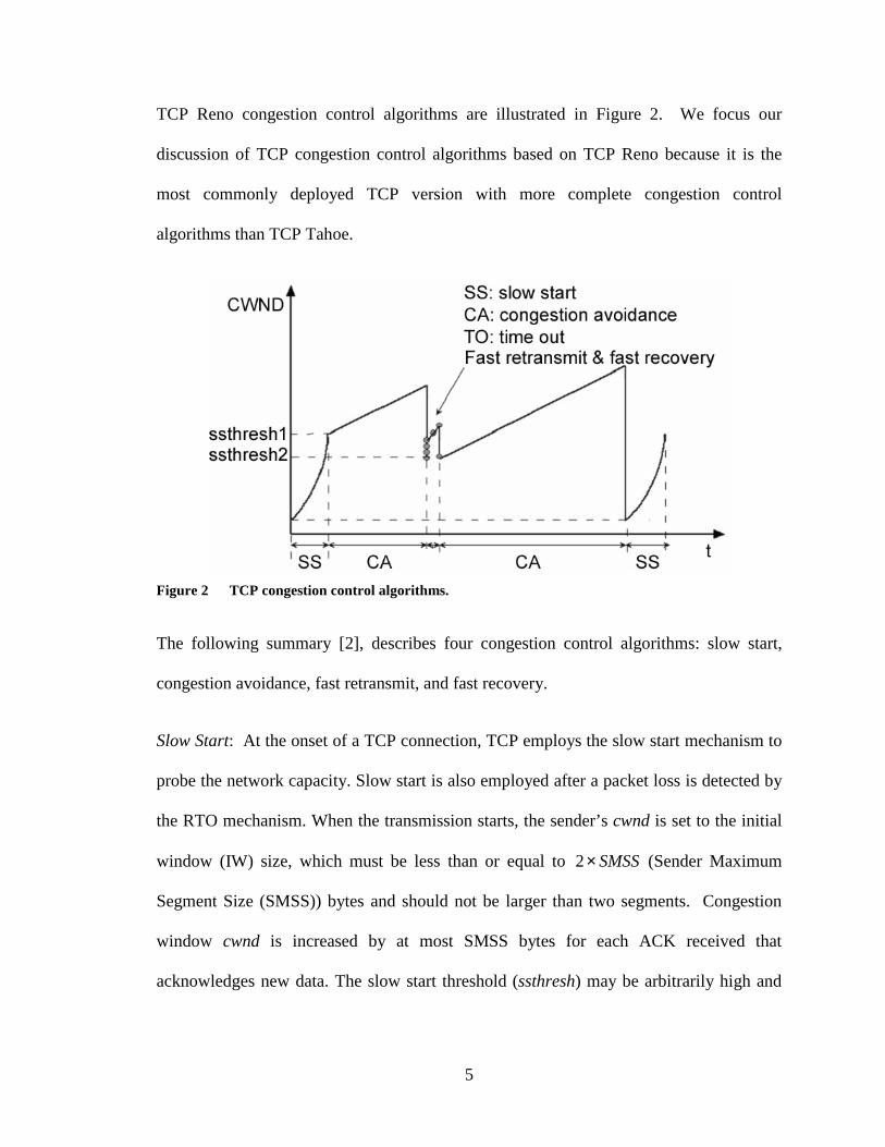
TCP Reno congestion control algorithms are illustrated in Figure 2. We focus our
discussion of TCP congestion control algorithms based on TCP Reno because it is the
most commonly deployed TCP version with more complete congestion control
algorithms than TCP Tahoe.
Figure 2 TCP congestion control algorithms.
The following summary [2], describes four congestion control algorithms: slow start,
congestion avoidance, fast retransmit, and fast recovery.
Slow Start: At the onset of a TCP connection, TCP employs the slow start mechanism to
probe the network capacity. Slow start is also employed after a packet loss is detected by
the RTO mechanism. When the transmission starts, the sender’s cwnd is set to the initial
window (IW) size, which must be less than or equal to 2 SMSS× (Sender Maximum
Segment Size (SMSS)) bytes and should not be larger than two segments. Congestion
window cwnd is increased by at most SMSS bytes for each ACK received that
acknowledges new data. The slow start threshold (ssthresh) may be arbitrarily high and
6
could be reduced when congestion occurs. When congestion is detected by the RTO
mechanism, cwnd is set to IW and ssthresh is set to 0.5×cwnd.
In both situations, slow start is used as long as cwnd < ssthresh. Slow start ends when
cwnd > ssthresh or when congestion is detected. When cwnd = ssthresh, the sender may
use either slow start or congestion avoidance.
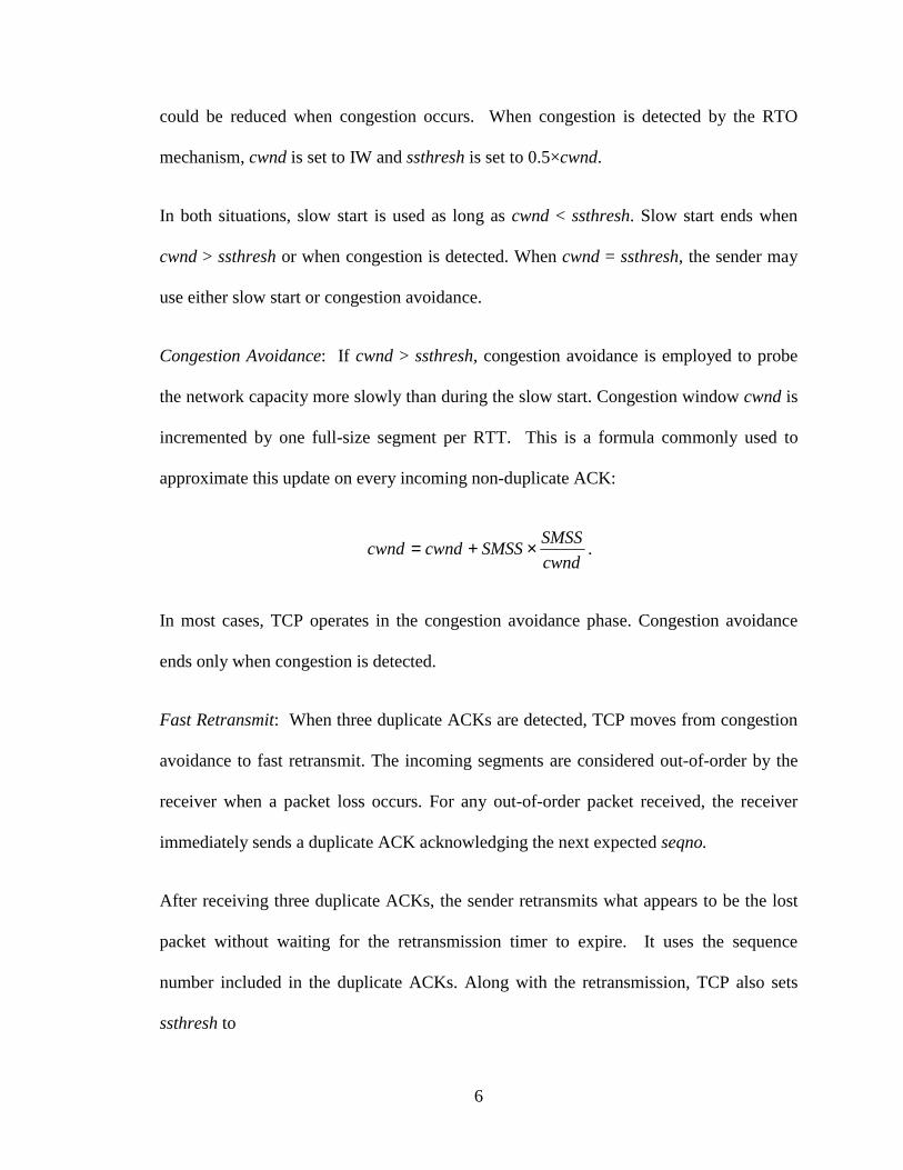
Congestion Avoidance: If cwnd > ssthresh, congestion avoidance is employed to probe
the network capacity more slowly than during the slow start. Congestion window cwnd is
incremented by one full-size segment per RTT. This is a formula commonly used to
approximate this update on every incoming non-duplicate ACK:
cwndSMSSSMSScwndcwnd ×+= .
In most cases, TCP operates in the congestion avoidance phase. Congestion avoidance
ends only when congestion is detected.
Fast Retransmit: When three duplicate ACKs are detected, TCP moves from congestion
avoidance to fast retransmit. The incoming segments are considered out-of-order by the
receiver when a packet loss occurs. For any out-of-order packet received, the receiver
immediately sends a duplicate ACK acknowledging the next expected seqno.
After receiving three duplicate ACKs, the sender retransmits what appears to be the lost
packet without waiting for the retransmission timer to expire. It uses the sequence
number included in the duplicate ACKs. Along with the retransmission, TCP also sets
ssthresh to

7
×= SMSSFlightSizessthresh 2,
2max .
FlightSize is the size of the outstanding data in the network.
Fast Recovery: Fast recovery takes place immediately after the sender performs fast
retransmit. It ends when a new ACK is received, where a new ACK is defined as the
ACK acknowledging the sequence number beyond the lost segment. TCP first inflates
cwnd to SMSSssthresh ×+ 3 . This reflects the three segments that have left the network
because three duplicate ACKs would require three packets to leave the network.
For every additional duplicate ACK received the sender increments cwnd by SMSS to
reflect that an additional segment has left the network. This new cwnd may also allow the
sender to transmit a new segment. When a new ACK is received, the sender sets cwnd to
ssthresh to deflate the cwnd, and the congestion avoidance phase continues.
1.1.3 Karn’s Algorithm: RTT Estimation and RTO
After a segment is transmitted, an ACK is expected by the sender. If the RTO timer
expires before the ACK is received, the segment is retransmitted. This resynchronizes the
transmission in case the segment is lost. Therefore, if the calculated RTO is too large,
unnecessary time will be spent waiting for the timer to expire. Thus, it will cause TCP
performance degradation [26]. If the calculated RTO is too small, the timer may expire
prematurely and cause unnecessary retransmissions.
RTT is estimated using Karn’s algorithm while RTO is calculated based on the estimated
RTT and the RTT deviation. TCP measures the round-trip time of the ACKs for data

8
segments. This interval is called sample RTT. The moving average of RTT, called a
smoothed RTT (srtt), and the RTT variation (rttvar) are calculated as
sampleRTTgsrttgsrtt **)1( +−=
rttvar *)1( h−= rttvar srttsampleRTTh −− * .
Recommended parameter values are
81=g and
41=h .
RTO is calculated as
4+= srttRTO rttvar.
1.2 Wireless Networks
Mobile connectivity provided by wireless networks [23] allows users to access
information anytime and anywhere. The growth of cellular telephone systems is
accompanied with an increased number of wireless-enabled laptops and Personal Digital
Assistants (PDAs). Cellular networks evolved from 1G analog systems to 2G systems
(Global System for Mobile communication (GSM) and Packet Data Cellular (PDC)),
2.5G systems (General Packet Radio Service (GPRS) and Packet Data Convergence
Protocol (PDC-P)), and 3G systems (Wideband Code-Division Multiple Access (CDMA)
and cdma2000). During the past decade, the quality of wireless links has been improved
in terms of Bit-Error Rate (BER) and link bandwidth. The following wireless network
characteristics still hold:

9
A. High bit error rate (BER)
Wireless networks experience random losses. BER in wireless networks is significantly
higher than in wireline networks. Packet error rates range from 1% in microcell wireless
networks, up to 10% in macrocell networks [27]. Even with optimized link layer
retransmission algorithms in 3G networks, such as Radio Link Protocol (RLP) and Radio
Link Control (RLC), packet error rate remains ~1%.
B. Long and variable delay
Wireless links have a large latency. Typical RTTs in 2.5G and 3G networks vary from a
few hundred milliseconds to one second. Furthermore, wireless links are likely to
experience sudden delay changes (or delay spikes, which are defined as a sudden increase
in the latency of the communication path [8].) greatly exceeding the typical RTT [15].
Wireless WANs have a typical latency of up to 1 sec. [14]. These delay changes may
cause spurious (unnecessary) TCP timeouts and fast retransmits. Wireless links
experience delay changes due to:
Link recovery: Wireless link recovers from a temporary link downtime due to radio
interference or mobility of the user, such as the user moves through a tunnel or a
building. While not significantly large, this type of delay is the major source of delay
variations.
Temporary disconnection: Mobile device recovers from handoff operations. Handoff is
the activity when a mobile user moves between cells. During handoffs, there is usually a
blackout period when there is no communication between mobile device and base station.

10
Traffic priority: Different traffic priorities are enforced in cellular networks. For
example, when there is a mixed traffic of voice and data, voice traffic has higher priority.
Link/MAC layer protocol: Certain wireless networks hide data losses from the sender by
performing extensive link-layer retransmission, causing variable delays in data
transmission [14].
C. Bandwidth
Bandwidth of cellular networks increases as they evolved from 1G analog systems to 2G
systems (10–20 kbps for uplink and downlink connections), to 2.5G (10–20 kbps uplink
and 10–40 kbps downlink connections), and 3G systems (up to 64 kbps uplink and 384
kbps downlink) [15].
Data rates vary due to mobility and the interference from other users [15]. Mobile users
share the bandwidth within a cell. As users move among cells, they affect the bandwidth
available to other users. Furthermore, a user may move to another cell with higher or
lower bandwidth. These factors cause variable wireless link data rates. TCP was designed
to handle the changes in bandwidth with its self-clocking scheme. However, a sudden
increase in RTT could still cause spurious timeouts.
D. Path asymmetry
Cellular networks, especially 2.5G and 3G systems, may run asymmetric uplink and
downlink data rates.

11
CHAPTER TWO: RELATED WORK
Wireless network characteristics have significant impact on TCP performance due to the
difference from wireline networks. Wireless links with considerable packet losses
because of link error, delay variations, and large sudden delay violate TCP’s essential
design assumptions. TCP was not designed with wireless network in mind. Hence, we
should not expect TCP to perform well in a wireless network [10].
Since mid 1990s, a great effort has been placed on improving TCP performance in
wireless environment. A number of solutions have been proposed to solve the problem
of non-congestion related packet losses misinterpreted by TCP [3], [4], [30]. In recent
years, researchers have also started to pay attention to the impact of delays and delay
variations on TCP performance in wireless networks [13], [14], [19], [20], [27], [33].
2.1 Wireless Link Error
The main characteristic of a wireless network is the high link BER. It violates the
fundamental assumption of TCP that packet losses caused by link errors are negligible
(much less than 1%) [16] and that packet losses are caused only by network congestion.
High BER in wireless networks causes packet loss regardless of network congestion. This
will cause TCP to unnecessarily reduce its transmission rate [9]. The main cause for
TCP's performance degradation in a mixed wireless/wireline environment is its inability
to detect the origin of the packet loss.
12
When a packet loss is detected, TCP employs congestion control algorithms to reduce the
transmission rate. A single packet loss will cause duplicate ACKs and cwnd to be reduced
by half according to the fast retransmit and fast recovery algorithms. TCP resolves the
congestion in the network by lowering its transmission rate. However, lowering the
transmission rate will degrade TCP performance if the packet loss is not caused by
network congestion.
(Note that wireless link errors are not the problem that I attempt to solve with my
proposed algorithms. Nevertheless, since they are a major part of the wireless TCP
research and most of the work has been done in this area, I will address it here for the
sake of completeness.)
2.2 Related Work Regarding Wireless Link Error
One approach to improving TCP performance is to reduce the adverse effect of wireless
link errors. Proposed solutions either hide the wireless link error from the TCP sender or
make the sender aware of the causes of segment losses [29]. The first approach resolves
the error within the wireless domain without the TCP sender being aware of the error.
These solutions often modify the base station and/or the mobile host. If the link error is
well shielded from the sender, modifying the sender is not necessary. The examples are
I-TCP [3], M-TCP [6], [31], [32] and Snoop [4], [5]. Since TCP sender cannot
differentiate the causes of segment losses, the second approach explicitly makes the
sender aware of the wireless link error and handles segment losses caused by wireless
link errors differently from losses due to network congestion. This approach requires that

13
the base station sends explicit congestion messages to the sender or a mechanism to
detect the causes of loss at the sender. An example is TCP Westwood [7].
A more general categorization is based on the algorithm design principles [1], [27].
The solutions may also be categorized as: split connection, link layer retransmission, and
end-to-end.
Split connection
Indirect-TCP (I-TCP) [3] is one of the first protocols proposed using this approach. As
illustrated in Figure 3, the TCP connection is split into two connections at the base station
(BS): between the fixed host (FH) and the BS (wireline domain) and between the BS and
the mobile host (MH) (wireless domain). For every TCP data segment received at the
BS, an ACK is generated at the BS on the wireline TCP connection. This ACK is then
sent to the sender (FH). The work to guarantee the actual delivery of TCP data is
imposed on the second connection in wireless network. Since the second connection is
within the wireless domain, an optimized protocol may be employed. The idea behind
this protocol is to hide the wireless losses from the sender. By using more optimised
wireless transport protocol, data have higher chance of getting successfully transmitted.

14
Figure 3 Split connection design.
The major drawback of this approach is that the TCP end-to-end semantics is not
preserved. Since an ACK is sent from BS to FH before the data segment is transmitted,
an ACK may be received at FH before the data segment is received at the MH or is even
lost. This is a serious issue for many applications. Another drawback is the software
overhead due to the establishment of two connections and due to the movement of data
segments between connections. This overhead introduces high latency at the BS. Buffers
are required for both connections. Hence, higher handoff latency is expected when the
content of the buffers needs to be transferred from one BS to another. The end-to-end
semantics was preserved in another proposed protocol in this category called M-TCP [6].
The simulation results of M-TCP’s performance evaluation in OPNET network simulator
[22] shows that M-TCP outperforms TCP in terms of maintaining congestion window
size, goodput, and sender size retransmission timer [31], [32].
Link layer retransmission
The Snoop protocol [4] is a well known protocol in this category. As illustrated in Figure
4, an agent is implemented at the link layer in BS. It hides wireless packet loss from the
sender (FH). Data segment received at the BS is first queued and then forwarded to the

15
MH. When a packet is lost in the wireless link, a local retransmission of the data
segments queued at the BS is performed. Therefore, loss is transparent to the FH.
Figure 4 Link layer design.
Snoop protocol has less overhead because it is implemented at the link layer. It has faster
recovery time due to the local retransmissions from the BS. As a result, it has typically
higher throughput than the split-connection approach. The major drawback of the Snoop
protocol is its data queue because per-connection buffers are required. Since the
unacknowledged segments need to be kept at the BS, the memory requirement becomes a
scalability issue. Another drawback is the increased handoff time, when the data queue
needs to be transferred between the two BSs. The third drawback is the increased delay
variation because Snoop solves segment losses individually [1] with local
retransmissions.
End-to-end
These protocols, such as TCP Westwood (TCPW) [7], require modification of TCP at the
sender (FH) and possible modifications in the BS or the MH. This is illustrated in Figure
5. The TCP sender continuously monitors the bandwidth used by the connection by
monitoring the rate of returning ACKs. The cwnd and ssthresh are calculated based on
16
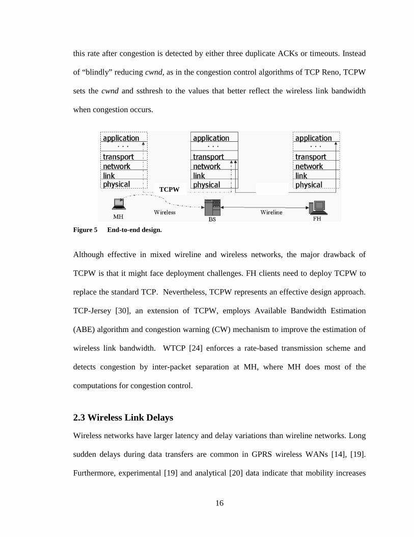
this rate after congestion is detected by either three duplicate ACKs or timeouts. Instead
of “blindly” reducing cwnd, as in the congestion control algorithms of TCP Reno, TCPW
sets the cwnd and ssthresh to the values that better reflect the wireless link bandwidth
when congestion occurs.
Figure 5 End-to-end design.
Although effective in mixed wireline and wireless networks, the major drawback of
TCPW is that it might face deployment challenges. FH clients need to deploy TCPW to
replace the standard TCP. Nevertheless, TCPW represents an effective design approach.
TCP-Jersey [30], an extension of TCPW, employs Available Bandwidth Estimation
(ABE) algorithm and congestion warning (CW) mechanism to improve the estimation of
wireless link bandwidth. WTCP [24] enforces a rate-based transmission scheme and
detects congestion by inter-packet separation at MH, where MH does most of the
computations for congestion control.
2.3 Wireless Link Delays
Wireless networks have larger latency and delay variations than wireline networks. Long
sudden delays during data transfers are common in GPRS wireless WANs [14], [19].
Furthermore, experimental [19] and analytical [20] data indicate that mobility increases
TCPW

17
packet delay and delay variation and degrades the throughput of TCP connections in
wireless environments. TCP reaction to the large sudden delays and delay variations has
not been widely studied in the past, since these properties are not common in wireline
networks. One of the earliest studies was conducted in [19], where the authors had
performed both experimental study and detailed analysis. Three major adverse effects
are identified as: spurious fast retransmit, spurious timeouts, and ACK compression.
Spurious fast retransmit: The primary source for unnecessary fast retransmit is the link
delay variations. A side effect of spurious timeout can also cause spurious fast
retransmit, which is explained in the next section. Delay variations can cause the re-
ordering of data segments during transmission. Since IP protocol does not guarantee in-
order delivery of packets, when there are delay variations on the transmission path, the
packets could be re-ordered. Therefore, when TCP runs over IP, TCP also experiences
out-of-order segments.
TCP generates a duplicate ACK whenever an out-of-order data segment is received. The
number of out-of-order segments that had arrived consecutively prior to the current
segment is called the re-ordering length [19]. Thus, the re-ordering length represents the
number of duplicate ACKs expected to arrive at the TCP sender. Figure 6 shows no
segment loss or network congestion. Nevertheless, fast retransmit is triggered because
TCP misinterprets the duplicate ACKs as packet loss and a sign of network congestion.
This event is called spurious fast retransmit.
TCP sender halves its congestion window to reduce the transmission rate in response to
fast retransmits. As illustrated in Figure 6, a packet was held in a queue by the hiccup (a

18
delay generator [19]) at time 37.7 sec (marked +) and then retransmitted after six
segments at time 41.9 sec (marked → ). Upon receiving the six segments prior to
receiving the queued segment, the receiver generates six duplicate ACKs, triggering a
fast retransmit. Since the congestion window is reduced, the number of segments that
can be sent into the network is also reduced.
Figure 6 The effect of packet re-ordering [19].
Spurious timeout: Unnecessary timeouts may occur on links with long sudden delays.
RTO is the conservative estimates of RTT. It is dynamically adjusted with running
average RTT and RTT variation. With its RTO timer, TCP is designed to handle even
large gradual changes in delays. Nevertheless, TCP cannot handle well long sudden
delays because it is unable to adjust its RTO fast enough. When the RTO timer expires,
TCP assumes that the outstanding packets are lost and triggers the congestion control.

19
Spurious timeout is illustrated in Figure 7 and Figure 8 (a finer view of Figure 7). The
three arrows show three critical events. The sudden long delay in the link occurs at 5 sec.
The first arrow indicates the moment when the TCP sender’s RTO timer expires. TCP
sender assumes that the previously sent packets are lost. The cwnd is reduced to the initial
window (two segments). TCP then retransmits the first two unacknowledged segments.
At 11 sec, the link delay terminates (marked by the second arrow). The sender receives
the first new ACK (the new ACK is defined as an ACK that acknowledges a data
segment which has not been acknowledged earlier) and starts recovering from timeouts
by entering the slow start phase. All the unacknowledged segments are to be
retransmitted. Since some ACKs in the wireless link have also been delayed, they
accumulate and arrive together at the sender when the link recovers. This causes a burst
of data segments to be sent. This is known as ACK compression. The retransmission
unnecessarily utilizes the scarce wireless bandwidth and may potentially increase the
recovery time.

20
Figure 7 TCP Reno: spurious timeout.
The unnecessary retransmission of segments may introduce an additional spurious fast
retransmit. At 11.97 sec, the retransmitted segments arrive at the receiver. Since
previously transmitted segments have been received after the link recovered, TCP
receiver generates a duplicate ACK for every out-of-order segment. These duplicate
ACKs (ACK 136) are shown between 11.97 sec and 12.54 sec. (These duplicate ACKs
between 11.97 and 12.54 sec are not shown in the cwnd graph because of the way ns-2
simulator generates traces. Ns-2 tracks the cwnd changes. Since these are duplicate
ACKs and the ACK number does not change, they are not recorded in the trace file.)
When the number of duplicate ACKs exceeds the duplicate ACK threshold, another
spurious fast retransmit is triggered. This further worsens the situation. A gap appears
after 12.54 sec (graph labelled seqno) immediately after ACK 137 is received. During the
fast recovery, for every duplicate ACK received, the sender artificially inflates the cwnd
by one segment and, if the cwnd permits, transmits the next segment. (Even though the

21
changes in cwnd graph are not shown during this period, this can be seen from the seqno
graph showing new segments that are sent with ACKs received. The reason that the
cwnd graph does not show the changes may be that TCP implementation in ns-2 makes
this change transparent to the cwnd variable. Therefore, cwnd appears to be unchanged in
the trace file.) When the new ACK 137 is received (marked by the third arrow), the fast
recovery is terminated and cwnd is deflated back to the size that it had at 11.97 sec. No
segments are transmitted during the period between 12.50 sec and 13.10 sec (graph
labelled seqno) due to this decrease of cwnd.
Figure 8 TCP Reno: spurious timeout.
ACK compression: ACK compression is another issue that possibly arises with wireless
link delays. The essence of TCP self-clocking is the observation that data segments
arrive at the receiver at the rate the bottleneck link can support. If the receiver’s ACKs
arrive at the sender with the equal spacing, then the sender can avoid congesting the

22
bottleneck link by sending new data packets at the same rate. The TCP self-clocking
depends on the arrival of ACKs at the spacing with which the receiver generated them. If
the spacing is altered or ACKs are accumulated during the transmission in the network,
the ACKs might be too close comparing to the spacing when they are sent. As a result,
the sender could send more data than the network can accept at an instance of time. The
phenomenon of ACK compression is observed even for TCP connections in wireline
networks.
2.4 Related Work Regarding Wireless Link Delays
Even though this is not the major part of the research on wireless TCP, it has attracted
some researchers to try to enhance TCP to adapt to various link delays experienced in
wireless networks.
Eifel algorithm [19] was proposed to enhance TCP’s adaptation to link delays in wireless
networks. Both spurious timeout and spurious fast retransmit are caused by TCP’s
retransmission ambiguity [18], which occurs when an ACK arrives for a segment that has
been retransmitted. Hence, there is no indication which transmission is being
acknowledged. Eifel algorithm is an end-to-end solution, which requires modifying only
the TCP sender and enabling timestamp option in the TCP receiver. It first eliminates the
retransmission ambiguity by using additional information in the ACKs. Then, it restores
the payload and resumes transmission with the next unsent segment [19]. Timestamp
option is used to provide the additional information to identify the segment that triggered
the duplicate ACK. Timestamp clock is stored in the header of every outgoing segment
and echoed back with its corresponding ACK. The sender also keeps track of the

23
timestamp of the first retransmission. The received ACK can be identified by comparing
the timestamp stored in the sender with the timestamp in the received ACK. If the ACK
was triggered by the original segment, spurious retransmission has occurred. The sender
then restores the cwnd and possibly RTO. Instead of retransmitting the unacknowledged
segments, the next unsent segment is transmitted.
Although Eifel algorithm effectively reduces the impact of spurious timeouts and
spurious fast retransmits by eliminating the retransmission ambiguity, it has two major
drawbacks: it requires modification of all TCP clients in the wireline domain and requires
that both the sender and the receiver have the 12-byte TCP timestamp option enabled in
every segment and the corresponding ACKs. Furthermore, its performance in the cases of
high link errors is questionable [13]. Even though the authors argue that this algorithm
does not require any modification on either wireless end device or any intermediate
router, inherited from the end-to-end scheme, requiring modification on all the TCP
clients in the wireline domain alone could face serious deployment challenge
Authors of [14] also studied the long sudden delays in GPRS wireless WAN.
Experiments were setup to investigate how the widely deployed TCP implementations
recover from a spurious timeout. Implementations on FreeBSD 4.1, Windows 98, Linux
2.2, and Linux 2.4 were tested. All were shown to have various levels of adverse effects,
along with several implementation faults. Few recommendations for possible
improvements were discussed.
24
CHAPTER THREE: PROPOSED TCP WITH PACKET CONTROL
We propose packet control algorithms designed to reduce the adverse effect of long
delays and delay variations on TCP performance in wireless networks. We will describe
the algorithms, their implementation, and performance evaluated using the ns-2 simulator
[21].
3.1 Proposed Solution
3.1.1 Network Architecture
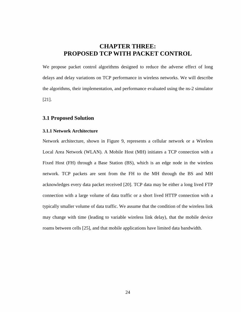
Network architecture, shown in Figure 9, represents a cellular network or a Wireless
Local Area Network (WLAN). A Mobile Host (MH) initiates a TCP connection with a
Fixed Host (FH) through a Base Station (BS), which is an edge node in the wireless
network. TCP packets are sent from the FH to the MH through the BS and MH
acknowledges every data packet received [20]. TCP data may be either a long lived FTP
connection with a large volume of data traffic or a short lived HTTP connection with a
typically smaller volume of data traffic. We assume that the condition of the wireless link
may change with time (leading to variable wireless link delay), that the mobile device
roams between cells [25], and that mobile applications have limited data bandwidth.

25
MH: mobile hostBS: base stationFH: fixed hostBSS: infrastructure
basic service set
FH
Wireline network
MH
MH
MHBS
BSS
MH
MH
MHMH BS
BSS/Cell
MH: mobile hostBS: base stationFH: fixed hostBSS: infrastructure
basic service set
FHFH
Wireline network
MH
MH
MHBS
BSS
MHMH
MHMH
MHMHBSBS
BSS
MH
MH
MHMH BS
MHMH
MHMH
MHMHMHMH BSBS
BSS/Cell
Figure 9 Network architecture.
3.1.2 Packet Control Algorithms
TCP with packet control consists of ACK and data packet filters. The two filters improve
TCP performance in mixed wireline/wireless networks and maintain TCP’s end-to-end
semantics. They deal with wireless links with long sudden delays and delay variations,
maintain regular TCP functions, and have small impact on handoffs. They do not depend
on end-user TCP flavours.
The filters are to be deployed at the wireless network edge (typically the BS). This is a
TCP-aware link layer solution. The algorithms keep track of TCP data and ACK packets
received from the FH and the MH respectively. Packet control filters forward packets to
both client ends based on the information gathered in the BS.
3.1.3 Design of Packet Control in Base Stations
After TCP connection is established, data is sent from FH to MH through BS. Upon
receiving data segments, MH sends acknowledgements to FH for every segment received
[20]. For simplicity, we do not consider the case when “delayed ACK” option [26] is
enabled in TCP receiver. Since all packets traverse through the intermediate node (BS),
BS is the good place to deploy packet control algorithms, without a need of any changes

26
in either FH or MH. Packet control is designed to focus on the spurious fast retransmit
and spurious timeout caused by delay variations and large sudden delays in wireless
links.
3.1.3.1 ACK Filter
Packet control is designed to reduce adverse effect of spurious fast retransmit. It reacts to
ACKs received from the MH using the ACK filter. It drops the old ACKs and duplicate
ACKs classified according to the duplicate ACK threshold defined by the user. It
remembers the last new ACK received from the wireless receiver, called the last received
ACK. When an ACK arrives, its ACK number is checked against the last received ACK.
We consider three cases:
Old ACK: The ACK is considered old if the ACK number has already been received and
is smaller than the last received ACK. It is immediately dropped at BS since there is no
need to transmit them to the sender and it would unnecessarily consume network
bandwidth.
Duplicate ACK: If the newly received ACK number is identical to the largest ACK
currently received, it is considered to be a duplicate. Packet control keeps track of the
current number of duplicate ACKs received at the BS. Based on the number of duplicate
ACKs received and the user-defined duplicate ACK threshold, duplicate ACKs are
evenly dropped and are not sent to the sender. The number of ACKs to be dropped is
equal to the difference between the user-defined duplicate ACK thresholds at the BS and
at the FH. For example, if the user-defined duplicate ACK threshold is six and TCP has
defined the three-duplicate-ACK threshold, every second duplicate ACK is dropped.

27
New ACK: If the ACK number has not been previously received, the ACK is considered
new. The last wireless ACK is updated, the counter for the current number of duplicate
ACKs is reset, and the ACK is forwarded to the sender.
The design of the ACK filter is based on the observation that a wireless link has higher
number of re-ordered segments, which is the primary cause of spurious fast retransmit.
By filtering some duplicate ACKs at the BS, the spurious fast retransmit may be reduced.
If the duplicate ACK is not caused by packet loss in the network, filtering duplicate
ACKs results in better TCP performance.
3.1.3.2 Data Filter
When the packet control receives a data segment from the FH, it passes it to the MH. The
data filter at the BS is designed to save wireless bandwidth and to prevent the spurious
fast retransmit caused by spurious timeout.
In the case of spurious timeout, retransmissions of the unacknowledged segments
unnecessarily consume the scarce wireless link bandwidth and also trigger additional
spurious fast retransmits. Therefore, their prevention is essential in solving spurious
timeout. The data filter checks whether data segments have been acknowledged. The
sequence number is checked against the last ACK received from the receiver. We
consider two cases:
New data segment or unacknowledged segment: If the segment has not been
acknowledged, it is forwarded to the receiver. The segment is either a new data segment
or an unacknowledged segment. In the latter case, the system cannot distinguish whether
the last transmission of the same segment has been received by the receiver or its ACK
28
was lost. In both cases, even if the received segment is a retransmission, it should be
forwarded.
Acknowledged segment: This segment is a retransmission due to spurious timeout. This
occurs because the ACK from the BS is lost or has not arrived at the FH. In both cases,
the segment should be dropped. We consider that a loss of ACKs could occur even
though the BER and the possibility of congestion for ACKs are small in wireline
networks. For every two identical retransmitted segments received, a corresponding ACK
is generated and sent from the BS to the sender. Hence, unnecessary retransmissions are
eliminated and the problem of lost ACKs is resolved.
3.1.4 Design Considerations and Tradeoffs
Packet control filters designed to deal with the wireless link delays have to be simple to
implement and easy to deploy. This has been reflected in various aspect of the design:
TCP option: Packet control has been designed as an option for TCP rather than a
modification of TCP. Hence, it is less difficult to deploy in an existing network. TCP is
the most successful and, more importantly, most tested transport protocol. TCP currently
can provide services for data application in wireless networks. Any new protocol would
require thorough validation and would face difficulties of deployment in the existing
network.
A link layer solution in BS: Packet control requires modification in the BS only. No
modifications are required at the end users. Furthermore, it can be deployed
incrementally because it does not require changes in the protocol stack.

29
Scalable: With proper implementation, packet control filters only require retaining few
constant state variables, and, hence, require minimal additional memory in the BS.
Handoff: Packet control requires very small additional operations during handoffs in
terms of additional memory requirements or message exchanges, and should not
adversely affect handoffs.
3.2 Performance
We implemented the packet control algorithms in ns-2.26 (ns-2.1b10 for old version
number) simulator on RedHat Linux 9. Simulations are conducted to investigate the
performance of the packet control algorithms comparing to TCP Reno. We used TCP
Reno rather than other version of TCP because TCP Reno has complete congestion
control algorithms and it is the most widely deployed version of TCP.
3.2.1 Implementation of TCP with Packet Control
The implementation followed closely the algorithms design described earlier. Figure 10
illustrates the logic flow of the ACK filter. The variable numOfLastDupAck indicates the
number of duplicate ACKs that have been received for the last received wireless ACK. It
is updated when a new ACK is received. It is then used, along with the user-defined
duplicate ACK threshold (redefine3DupAck), to determine whether an ACK should be
sent or dropped. The next duplicate ACK to be sent (nextDupAckToSend) is calculated as:
−=
33
1DupAckredefinedupAcknumOfLastDkSentnumOfDupAc

30
( )331 DupAckredefinekSentnumOfDupAcToSendnextDupAck ×+= .
The variable numOfDupAckSent is the number of duplicate ACKs that should be sent,
triggered by the previous duplicate ACKs received. This ensures that duplicate ACKs
will be evenly sent to the sender according to the user-defined duplicate ACK threshold
in the BS.
Figure 10 Packet control: ACK filter.
Figure 11 illustrates the logic flow of data filter. The variable lstRetransWiredDataPkt
stores the segment numbers of retransmitted segments from the FH. A retransmitted
segment is defined as a segment with the sequence number smaller or equal to the largest
ACK number that has already been sent to the FH. These retransmitted segments are
dropped. The number of retransmissions for each retransmitted segment (m_iNumOfRtm)

31
is kept in the list for each segment. An ACK for a segment is generated and sent to the
FH for every second retransmission of the same segment. This handles the rare situations
when an ACK is lost along the path from the BS to the FH.
Figure 11 Packet control: data filter.
3.2.2 Performance of TCP with Packet Control
The simulated network is illustrated as shown in Figure 12. (For implementation
purpose, the network setup used for ns-2 simulations consists of one additional node. It
has been omitted here for simplicity.) The simulated network reflects our network
architecture. A wired link connects the FH to the BS, while a wireless link connects the
BS and the MH.
Figure 12 Simulated network setup.
FH MH BS
1 Mbps 250 Kbps
32
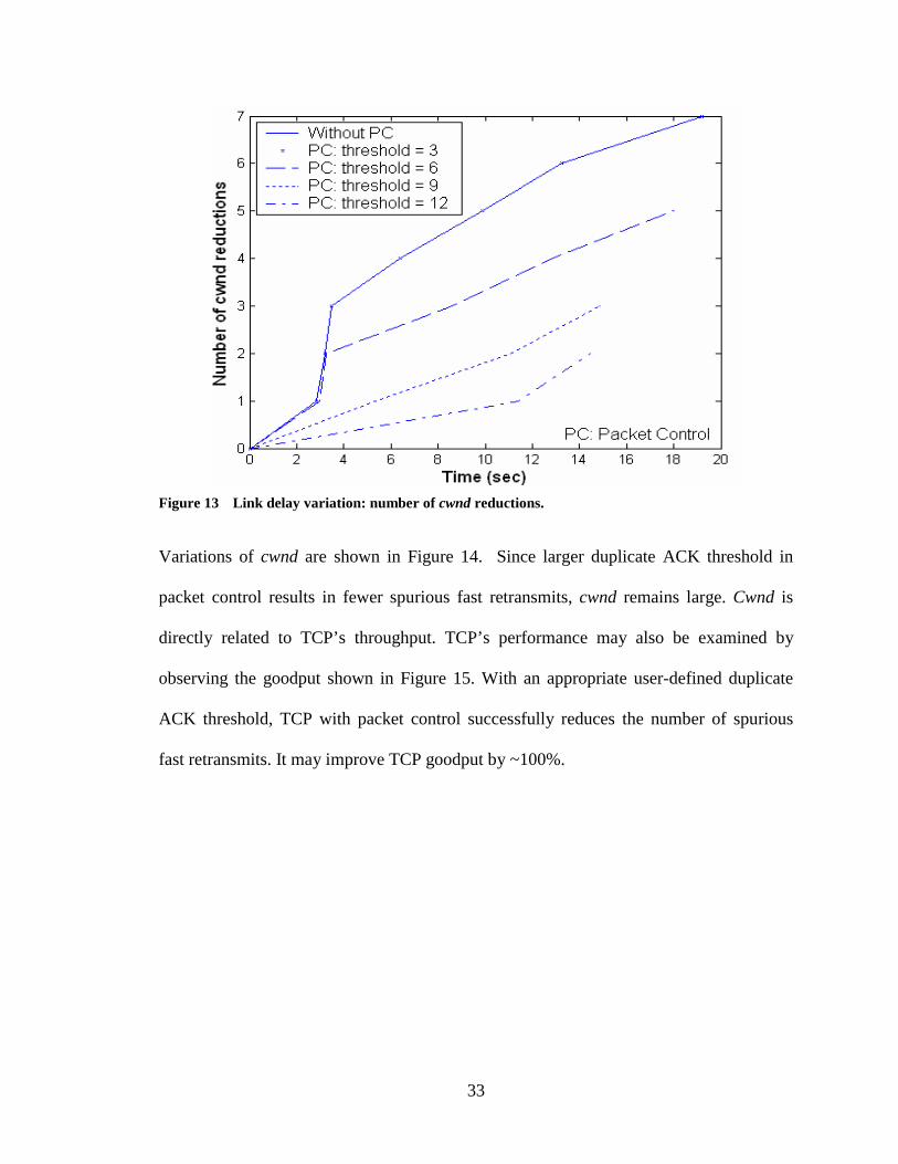
3.2.2.1 Scenario I: Link Delay Variation with Small Delay
This scenario is used to investigate TCP’s reaction to link delay variations. For 20 sec,
FTP (with TCP Reno) data are being sent from the FH to the MH in TCP packets of
1,040 bytes (default in ns-2). Link capacity between FH and BS is 1 Mbps, with 5 msec
of delay. Link capacity between BS to MH is 250 kbps, with 170 msec of variable delay.
Link delay variation is introduced at 0.5 sec. Links employ DropTail queues.
The simulation results show improvement in TCP performance. The number of cwnd
reductions vs. time is shown in Figure 13. Due to the spurious fast retransmit caused by
link delay variation, TCP without packet control has the largest number of cwnd
reductions. It also implies the largest number of fast retransmits. TCP with packet control
and the user-defined duplicate ACK threshold set to 12 has the smallest number of cwnd
reductions. The larger the duplicate ACK threshold, the more duplicate ACKs will be
dropped and fewer fast retransmits will be performed by TCP. These fast retransmits are
spurious and reducing them results in higher TCP performance.
Graph with no packet control and graph with user-defined duplicate ACK threshold of
three overlap, validating the implementation of the filters. Since TCP sender also has the
threshold of three, no duplicate ACKs are dropped and the two cases coincide.
33
Figure 13 Link delay variation: number of cwnd reductions.
Variations of cwnd are shown in Figure 14. Since larger duplicate ACK threshold in
packet control results in fewer spurious fast retransmits, cwnd remains large. Cwnd is
directly related to TCP’s throughput. TCP’s performance may also be examined by
observing the goodput shown in Figure 15. With an appropriate user-defined duplicate
ACK threshold, TCP with packet control successfully reduces the number of spurious
fast retransmits. It may improve TCP goodput by ~100%.

34
Figure 14 Link delay variation: cwnd.
Figure 15 Link delay variation: goodput.

35
3.2.2.2 Scenario II: Link Delay Variation with Small Delay and Link Errors
Even though link error is not the problem our algorithms are targeting to solve, it would
still be interesting to see how packet control reacts to it. Based on the experiments in
Scenario I, we conducted another set of similar experiments to investigate the case with
1% bidirectional packet loss in the wireless link. (We are interested in 1% packet loss
because that link layer retransmission protocols, such as RLP and RLC, used in Third
Generation (3G) cellular networks ensure packet loss probability of less than 1% [15].)
TCP goodput is shown in Figure 16. With user-defined duplicate ACK threshold of 9,
TCP with packet control achieves ~30% improvement.
Figure 16 Link delay variation (1% segment loss): goodput.
3.2.2.3 Scenario III: Spurious Timeout
We also investigate TCP’s reaction to sudden large delay increase. It has similar settings
as in Scenario I. Instead of introducing variable delays at wireless link, a delay of 6 sec is
introduced at time instance equal to 5 sec.

36
The reaction of TCP without packet control to the long sudden delay is shown in Figure 7
and Figure 8. They clearly show the adverse effect of spurious timeout and the spurious
fast retransmit caused by the unnecessary retransmissions. Identical simulation scenario,
with packet control enabled, is used to generate the results shown in Figure 17. They
illustrate that TCP recovers faster (indicated by the third arrow) than in the case shown in
Figure 8. Finer versions of both scenario results (from 10 sec to 13.5 sec) are shown in
Figure 18 and Figure 19. As shown in Figure 18, the gap where TCP receives duplicate
ACKs and the gap where TCP cannot send new data due to deflation of cwnd are much
smaller than gaps shown in Figure 19.
Figure 17 TCP with packet control: spurious timeout.

37
Figure 18 TCP with packet control: spurious fast retransmit caused by spurious timeout.
Figure 19 TCP Reno: spurious fast retransmit caused by spurious timeout.
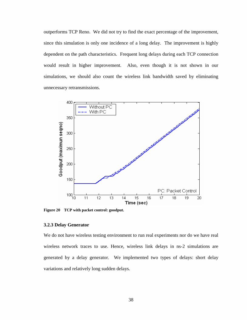
A comparison of TCP goodput is shown in Figure 20. The dotted line in the graph
represents the scenario with packet control. It is evident that TCP with packet control
38
outperforms TCP Reno. We did not try to find the exact percentage of the improvement,
since this simulation is only one incidence of a long delay. The improvement is highly
dependent on the path characteristics. Frequent long delays during each TCP connection
would result in higher improvement. Also, even though it is not shown in our
simulations, we should also count the wireless link bandwidth saved by eliminating
unnecessary retransmissions.
Figure 20 TCP with packet control: goodput.
3.2.3 Delay Generator
We do not have wireless testing environment to run real experiments nor do we have real
wireless network traces to use. Hence, wireless link delays in ns-2 simulations are
generated by a delay generator. We implemented two types of delays: short delay
variations and relatively long sudden delays.

39
Short delay variations are generated based on the measurements of packet delays in
wireless data networks [20]. The configuration for TCP performance measurement is
based on CDMA 1xRTT network architecture. A mobile host in a wireless network was
connected to a host computer in a wired Local Area Network (LAN) through a single BS.
During the entire experiment, the mobile host was connected to the same BS. The “ping”
application was generated by the Internet Control Message Protocol (ICMP) ECHO. In
one scenario named “Ping Wireless Mobile Terminal”, ping packets were sent from the
host computer in the LAN to the mobile terminal moving at pedestrian speed. “Figure 3”
[20] provided the Cumulative Distribution Function (CDF) for packet delay (or RTT) for
this scenario.
Based on this figure, we derived delay values used in simulations, as shown in Table 1.
Each case is simulated with a uniform distribution generated by the ns-2 random
generator. The delays are in agreement with results reported in [8], varying from 179
msec to 1 sec in a 3G1X system. The wireline link delay was kept constant at 5 msec.
Table 1 Wireless delay for mobile terminals.
Percentage (%)
Total RTT (ms)
Wireline RTT (ms)
Wireless RTT (ms)
Wireless Link Delay (ms)
80 316 – 400 10 306 – 390 153 – 195
10 400 – 460 10 390 – 450 195 – 225
8 460 – 605 10 450 – 595 225 – 297
2 605 – 1,252 10 595 – 1,242 297 – 621
A long delay was generated by a timer. The only criterion was to have a delay long
enough to generate a timeout in TCP. The one-way wireless link delay was kept constant

40
at 170 msec. This value is close to the ~300 msec average RTT reported in [20]. The
sudden increase of delay was simulated for 6 sec, which was sufficiently long to cause a
regular TCP timeout with at least one exponential back-off.
3.2.4 NS-2 Implementation
Network simulator ns-2 is a discrete event simulator developed for networking research.
It provides substantial support for simulation of TCP, routing, and multicast protocols
over wired and wireless (local and satellite) networks [21]. The simulator is written in
C++ because of its rich computer programming capability, object oriented programming
model, and the speed. It uses Object Tool Command Language (OTcl) to script the
simulation scenario setups and perform result analysis. OTcl is an extension to Tcl/Tk
for object-oriented programming. It was chosen for its simplicity and flexibility.
One can modify or extend the existing ns-2 models in C++ to fit various simulation
needs. An ns-2 simulation typically involves node creation and configuration, packet
forwarding, link creation, queue management, error model, network setup, and trace
collection. A typical structure of a unicast node is as shown in Figure 21. Two
classifiers (address and port classifier) distribute incoming packets to the correct agent or
outgoing link [21].

41
Figure 21 Structure of a unicast node [21].
The packet control (for historical reasons, we used “ACK Control” in the code to mean
“packet control”) algorithms are mostly implemented in the link layer of a BS. The ns-2
link layer implementation (class LL) was extended by defining and exporting variables,
such as enableAckControl_ and Redefine3DupAck_. It overwrites the recv() function to
implement various aspects of the packet control algorithms.
/** * Packet Control for Wireless TCP implemented as a link layer solution with TCP awareness. */ class LLWz : public LL {
int enableAckControl_; // 0 - enable the packet control, 1 - disable int m_iRedefine3DupAck; //in seconds. //overwrite recv(..). virtual void recv(Packet* p, Handler* h);
};

42
//export properties to OTcl, so that user can change these // properties through OTcl in their simulation scripts. bind("enableAckControl_", &enableAckControl_); bind("Redefine3DupAck_", &m_iRedefine3DupAck);
In the OTcl simulation script, this allows using the new link layer in BS node, enabling
packet control, and set user-defined duplicate ACK thresholds. The following example
enables packet control in BS node with user-defined duplicate ACK threshold equal to 8:
# Use Packet Control Link Layer on BS ($node(0) in our network setup) $lan addNode [list $node(0)] $opt(bw) $opt(delay) LL/LLWz $opt(ifq) $opt(mac) # get LL object of BS set nif [$lan set lanIface_($node(0))] ;#get network interface object. set llBS [$nif set ll_] # configure Packet Control $llBS set enableAckControl_ 1 //enables packet control $llBS set Redefine3DupAck_ 8 //set user defined dup ACK to 8 $node(0) label "n0 <AC [$llBS set enableAckControl_]>"
In the similar way, we extended delay model in ns-2 to be able to generate long delay and
delay variations:
class LinkDelay : public Connector { // define the delay modes. enum LinkDelay_DelayMode { LD_DelayMode_Constant = 0, //constant delay. LD_DelayMode_Random //variable delay. };
double m_dWirelessDownTime; double m_dWirelessDownDuration;
int delayMode_; //delay mode.
}

43
// export properties to OTcl. bind("delayMode_", &delayMode_); bind("WirelessDownTime_", &m_dWirelessDownTime); bind("WirelessDownDuration_", &m_dWirelessDownDuration);
Once the above properties are implemented and exported to OTcl, we then can configure
the wireless link delays in simulation scripts. Example 1 starts a delay at 5 sec after
simulation lasts 6 sec. Example 2 shows a part of the code that enables the variable delay
in our performance evaluation Scenario I.
Example 1: ~~~~~~~~ DelayLink set delayMode_ 0; #0 - constant, 1 - LD_DelayMode_Random DelayLink set WirelessDownTime_ 5.0; DelayLink set WirelessDownDuration_ 6.0; $d label "d <delay [DelayLink set delayMode_]>" set lanDest [$ns make-lan $nodelistDestLan $opt(bw) \
$opt(delay) $opt(ll) $opt(ifq) $opt(mac) $opt(chan)] Example 2: ~~~~~~~~ DelayLink set delayMode_ 1; #0 - constant, 1 - LD_DelayMode_Random #the data in this delay is from K. Luo and A. O. Fapojuwo paper. proc changeDelay {} { global d node delayPercent delay1 delay2 delay3 delay4 set ns [Simulator instance] set now [$ns now] set whichDelay [$delayPercent value] if ($whichDelay<80) then { set new_delay [$delay1 value] } elseif ($whichDelay<90) then { set new_delay [$delay2 value] } elseif ($whichDelay<98) then { set new_delay [$delay3 value] } else { set new_delay [$delay4 value] }

44
$ns delay $d $node(1) $new_delay duplex ;#duplex ;#simplex set time 0.0005; $ns at [expr $now+$time] "changeDelay" }
3.2.5 Performance Comparison
In our simulation, we compared the performance of TCP with packet control with TCP
Reno. Due to the lack of time, we have not performed comparisons with other proposed
algorithms. This comparison would be certainly useful. Eifel algorithm is the only
known solution proposed specifically to improve TCP performance in wireless networks
with respect to long sudden delay and delay variation. Hence, it is necessary to compare
performance of packet control and Eifel algorithms. Despite the drawbacks of Eifel
algorithm that we discussed earlier, in terms of performance only, Eifel algorithm would
still outperform TCP with packet control because the best packet control can do is to
prevent spurious fast retransmit caused by spurious timeout. In contrast, Eifel algorithm
not only tries to do this, but also tries to reverse the adverse effects of spurious timeout
already performed (TCP sender’s cwnd and ssthresh). However, packet control would
perform better in wireless bandwidth savings and avoiding network congestion.
Furthermore, Eifel algorithm is an end-to-end solution, while packet control is a TCP
aware link layer solution.

45
CHAPTER FOUR: CONCLUSIONS
In this research, we first studied various issues and related work dealing with TCP in
wireless networks. We then proposed packet control filters to improve TCP performance
in wireless networks with delay variations and long sudden delays. TCP connections
were simulated in a mixed wireline and wireless network using the ns-2 simulator. The
simulation results show that the proposed algorithms reduce spurious fast retransmit and
spurious timeouts in TCP. They improve TCP’s response time, goodput, and bandwidth
consumption. Goodput of TCP Reno is improved by ~100% in networks with delay
variations and by ~30% in networks with 1% packet losses in the wireless link. In cases
of long sudden delays, TCP performance is also improved, depending on the path
characteristics.
Even though our algorithms may be further enhanced, we showed that packet control
filters can be conveniently deployed at the intermediate routers to control the
transmission of TCP segments and ACKs.

46
CHAPTER FIVE: FUTURE WORK
Future improvements of the proposed algorithms may include:
Existing algorithm improvement: Even though we have illustrated the effectiveness of our
algorithms, these algorithms could be further improved.
Delay generator: Further analysis of delay generators is required for simulations. More
accurate delay generator or genuine wireless traces should be used for the analysis and
performance evaluation.
Multi-connections: Multi-connection simulation scenarios could be considered.
ACK compression: Algorithms to deal with ACK compression caused by wireless
network delays should also be considered. This is especially important when considering
possible congestion in a presence of multiple connections. The ACKs are accumulated
during long delay. When link recovers, TCP senders generate bursty traffic that triggers
network congestion, especially at the wireless edge note (BS).
If long delays could be detected, BS can then control the rate ACKs are forwarded to the
sender. The idea is to smooth out the burstiness of TCP transmission by controlling the
ACK rate [17]. There are two related issues: how to detect long delays and how to
determine the proper rate. It will be very useful to consult the work that has been done in
end-to-end solutions for TCP rate control [7], [24], [30].

47
End-to-End solution consideration: Even though this has the least priority on this list, it
will be interesting to consider the possibility of the end-to-end approach based on the
knowledge in the BS. Changes could be made in the TCP sender to convey sender
information to a BS. The BS can then generate events (packets) to control TCP sender
with both sender information and information at the BS.
48
REFERENCE LIST
[1] A. Aaron and S. Tsao, “Techniques to improve TCP over wireless links,” Final Report, EE 359, Stanford University, December 2000.
[2] M. Allman, V. Paxson, and W. Stevens, “TCP congestion control,” IETF RFC 2581, April 1999.
[3] A. Bakre and B. R. Badrinath, “I-TCP: indirect TCP for mobile hosts,” in Proc. 15th International Conference on Distributed Computing Systems (ICDCS), Vancouver, BC, May 1995, pp. 136–143.
[4] H. Balakrishan, S. Seshan, E. Amir, and R. H. Katz, “Improving TCP/IP performance over wireless networks,” in Proc. ACM MobiCom, Berkeley, CA, November 1995, pp. 2–11.
[5] J. Border, M. Kojo, J. Griner, G. Montenegro, and Z. Shelby “Performance enhancing proxies,” Internet Draft [Online]. Available: http://community. roxen.com/developers/idocs/drafts/draft-ietf-pilc-pep-04.html.
[6] K. Brown and S. Singh, “M-TCP: TCP for mobile cellular networks,” ACM SIGCOMM Computer Communication Review, vol. 27, no. 5, pp. 19–42, October 1997.
[7] C. Casetti, M. Gerla, S. Mascolo, M.Y. Sanadidi, and R. Wang, “TCP Westwood: end-to-end congestion control for wired/wireless networks,” Wireless Networks (WINET), vol. 8, no. 5, pp. 467–479, September 2002.
[8] M. C. Chan and R. Ramjee, “TCP/IP performance over 3G wireless links with rate and delay variation,” in Proc. ACM MobiCom, Atlanta, GA, September 2002, pp. 71–82.
[9] D. Chandra, R. Harris, and N. Shenoy, “TCP performance for future IP-based wireless networks,” 3rd IASTED International Conference on Wireless and Optical Communications (WOC2003), Banff, Canada, July 2003.
[10] H. Elaarag, “Improving TCP performance over mobile networks,” Journal of ACM Computing Surveys, vol. 34, no. 3, pp.357–374, September 2002.
[11] S. Floyd and T. Henderson, “The NewReno modification to TCP’s fast recovery algorithm,” IETF RFC 2582, April 1999.
[12] S. Floyd, “A report on recent developments in TCP congestion control,” IEEE Communications Magazine, vol. 39, no. 4, pp. 84–90, April 2001.
[13] S. Fu, M. Atiquzzaman, and W. Ivancic, “Effect of delay spike on SCTP, TCP Reno, and Eifel in a wireless mobile environment,” in Proc. International Conference on Computer Communications and Networks, Miami, FL, October 2002, pp. 575–578.

49
[14] A. Gurtov, “Effect of delays on TCP performance,” in Proc. IFIP Personal Wireless Communications (PWC'01), Lappeenranta, Finland, August 2001.
[15] H. Inamura, G. Montenegro, R. Ludwig, A. Gurtov, and F. Khafizov, “TCP over second (2.5G) and third (3G) generation wireless networks,” IETF RFC 3481, February 2003.
[16] V. Jacobson, “Congestion avoidance and control,” in Proc. ACM SIGCOMM, Stanford, CA, August 1988, pp. 314–329.
[17] S. Karandikar, S. Kalyanaraman, P. Bagal, and B. Packer, “TCP Rate Control,” ACM SIGCOMM Computer Communication Review, vol. 30, no. 1, pp. 45–58, January 2000.
[18] P. Karn and C. Partridge, “Improving round-trip time estimates in reliable transport protocol,” ACM Transactions on Computer Systems, vol. 9, no. 4, pp. 364–373, November 1991.
[19] R. Ludwig and R. H. Katz, “The Eifel algorithm: making TCP robust against spurious retransmission,” ACM Computer Communications Review, vol. 30, no. 1, pp. 30–36, January 2000.
[20] K. Luo and A. O. Fapojuwo, “Impact of terminal mobility on TCP congestion control performance,” in Proc. 3rd IASTED International Conference on Wireless and Optical Communications, Banff, Canada, July 2003, pp. 360–365.
[21] ns–2 [Online]. Available: http://www.isi.edu/nsnam/ns.
[22] OPNET documentation V.8.0.B, OPNET Technologies Inc., Washington DC.
[23] R. Prasad and M. Ruggieri, Technology trends in wireless communications, Artech House, Boston, MA, 2003.
[24] P. Sinha, N. Venkitaraman, R. Sivakumar, and V. Bhargavan, “WTCP: a reliable transport protocol for wireless wide-area networks,” in Proc. ACM MobiCom, Seattle, WA, August 1999, pp. 231–241.
[25] S. Singh, “Quality of service guarantees in mobile computing,” Journal of Computer Communications, vol. 19, no. 4, pp. 359–371, April 1996.
[26] W. Stevens, TCP/IP Illustrated, Volume 1: The Protocols. Reading, MA: Addison-Wesley, Professional Computing Series, 1984.
[27] I. Stojmenovic, Handbook of Wireless Networks and Mobile Computing. New York, NY: John Wiley & Sons, 2002.
[28] Information Sciences Institute, “Transmission control protocol,” IETF RFC 793, September 1981.
[29] V. Tsaoussidis and I. Matta, “Open issues on TCP for mobile computing,” The Journal of Wireless Communications and Mobile Computing, John Wiley & Sons, vol. 2, no. 1, February 2002.
[30] K. Xu, Y. Tian, and N. Ansari, “TCP-Jersey for wireless IP communications,” IEEE Journal on Selected Areas in Communications, vol. 22, no. 4, pp. 747–756, May 2004.

50
[31] W. Zeng, H. Zhang, J. Liu, N. Cackov, S. Vujicic, B. Vujicic, V. Vukadinovic, and Lj. Trajkovic, “Improvement of TCP over wireless links,” The ASI Exchange, Vancouver, BC, Canada, March 2003. (Poster)
[32] W. G. Zeng, M. Zhan, Z. Li, and Lj. Trajkovic, “Performance evaluation of M-TCP over wireless links with periodic disconnections,” OPNETWORK 2003, Washington, DC, August 2003.
[33] W. G. Zeng and Lj. Trajkovic, “TCP packet control for wireless networks,” IEEE Int. Conf. on Wireless and Mobile Computing, Networking and Communications (WiMob 2005), Montreal, Canada, August 2005, pp. 196–203.