TCOM 515 IP Routing. Syllabus Objectives IP header IP addresses, classes and subnetting Routing...
32
TCOM 515 IP Routing
-
Upload
jonah-hudson -
Category
Documents
-
view
240 -
download
1
Transcript of TCOM 515 IP Routing. Syllabus Objectives IP header IP addresses, classes and subnetting Routing...

TCOM 515
IP Routing
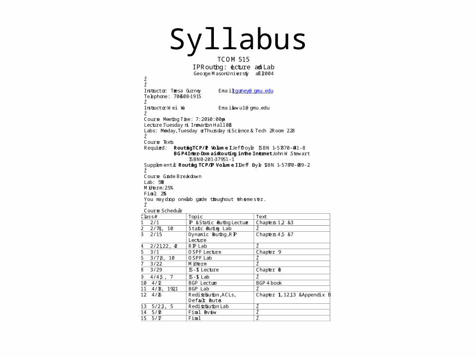
SyllabusTCOM 515
IP Routing: Lecture and LabGeorge MasonUniversity Fall 2004
ŹŹInstructor: Teresa Gurney Email:[email protected]: 703-608-1915ŹInstructor: Wei Wu Email:[email protected]ŹCourse Meeting Time: 7:20-10:00pmLecture: Tuesday in Innovation Hall 206Labs: Monday, Tuesday or Thursday in Science & Tech 2 Room 228ŹCourse TextsRequired: RoutingTCP/IP Volume I Jeff Doyle ISBN 1-57870-041-8
BGP4Inter-DomainRouting in the Internet John W.StewartISBN0-201-37951-1
Supplemental: Routing TCP/IP Volume II Jeff Doyle ISBN 1-57870-089-2ŹCourse Grade BreakdownLab: 50%Midterm: 25%Final: 25%You may drop one lab grade throughout the semester.ŹCourse Schedule
Class # Topic Text1 2/1 IP & Static Routing Lecture Chapters 1,2 & 32 2/7,8, 10 Static Routing Lab Ź3 2/15 Dynamic Routing, RIP
LectureChapters 4,5 & 7
4 2/21, 22, 24 RIP Lab Ź5 3/1 OSPF Lecture Chapter 96 3/7, 8, 10 OSPF Lab Ź7 3/22 Midterm Ź8 3/29 IS-IS Lecture Chapter 10
9 4/4, 5 , 7 IS-IS Lab Ź10 4/12 BGP Lecture BGP4 book11 4/18, 19, 21 BGP Lab Ź12 4/26 Redistribution, ACLs,
Default RoutesChapter 11,12, 13 & Appendix B
13 5/2, 3, 5 Redistribution Lab Ź14 5/10 Final Review Ź15 5/17 Final Ź

Objectives
• IP header • IP addresses, classes and subnetting• Routing tables• Routing decisions• Directly connected routes• Static routes

What is Routing?
•Routing operates at the 3rd layer of the OSI model,
the network layer.
•A router uses routing algorithms to select the best to
any given destination.
•A packet is routed from a source across one or more
networks to the identified destination.
•To select the best path, router builds a routing table
from information its own configuration and from
updates sent from other routers.

• First a router receives a packet inbound on one
of its local interfaces.
• Then the router looks into the IP header of the
given packet at the destination IP specified.
• Next the router looks into its routing table and
selects the best path to that destination.
• Finally the router updates the IPpacket with the
next hop and sends the packet along its way
through the network.
How does routing work?

OSI Model
http://www.cisco.com/univercd/cc/td/doc/cisintwk/ito_doc/ip.htm

Routing in the OSI ModelRouting takes place at the Network Layer of the
OSI Model. It uses the information in the IP packet header, specifically the IP address of the destination network, to make decision and send it along the network.
IP packets encapsulate TCP and UDP datagrams, but they are not touched during the routing processes. Once a packet reaches The local network of its destination IP, layer 2, Link Layer, uses its protocol to deliver the packet.

Routers
Routers - device that sends a packet (set of data) along a route
from one network to another. It first checks for the destination
of the packet on its local or directly connected interfaces. If
the destination is not local it looks in its routing table for a
route to the destination. Any non-local route is learned from
a routing protocol running on the router.

Routing Protocols
Routing Protocol - set of procedures used by routers
to determine and use the optimal router and to share
its network information with other routers. This routing
protocol guides how to send its information to other routers,
how to receive and process information from other routers,
and how to select the best path to each desination network.
That destination and optimal path are used to build a routing
table.

IP Packet Header
http://www.cisco.com/univercd/cc/td/doc/cisintwk/ito_doc/ip.htm

Version - 4 bit - IP version IPv4 (0100) or IPv6 (0110)
IP Header Length (IHL) - 4 bit - indicates the datagram header length in 32-bit words, including options.
Type-of-Service - 8 bit -information for higher layer protocols on handling and priority levels, broken into precedence and TOS
Total Length - 16 bit - length of IP packet, in terms of bytes, including both data and header.
Identification - 16 bit - Contains an integer that identifies the current datagram. This field is used to help piece together datagram fragments.
Flags - 3 bit - First bit is unused. The second bit is the DF, Do Not Fragment bit, which generates an error and drops the packet if fragmentation is needed. The last bit is the MF, More Fragments bit, which tells the router whether or not more fragments are coming. MF = 0 means that it is the last fragment.
Fragment Offset - 13 bit - Specifies fragmentation offset in terms of eight octet units from the beginning of the IP header. Used to order fragments once all are received.
IP Packet Header Fields

Time-to-Live - 8 bit - Hop count that is decremented by each router that touches the packet. TTL is used to prevent endless loops and routing problems. Once TTL = 1 or 0, the packet is dropped and ICMP error message is sent to source.
Protocol - 8 bit - Specifies the next higher level protocol of host-to-host or transport protocol. TCP (00000110) UDP (00010001)
Header Checksum - 16 bit - One’s complement checksum of original packet, compared to calculation of receiver’s packet. Recalculated at each router because of TTL change.
Source Address - 32 bit - IP address of sender.
Destination Address - 32 bit - IP address of intended receiver
Options - Variable Length - allows for further information including, routing info types: loose or strict, record route and timestamps. Uses padding to finish 32 bit words.
Data - higher layer ( TCP or UDP ) datagram
IP Packet Header Fields

IP Addressing ReviewIP Addresses have 32 bits broken into 4 octets. They are expressed in dotted decimal notation. Addresses may range from 0.0.0.0 to 255.255.255.255. Address rangesare assigned by Internet Assigned Numbers Authority IANA, who in turns assigns IP ranges to Regional Internet registry.
http://www.cisco.com/univercd/cc/td/doc/cisintwk/ito_doc/ip.htm

IP Subnet Classes
Class Range Purpose Number of Hosts
A 1.0.0.0 -> 126.0.0.0 Large Organizations 16,777,214
B 128.1.0.0 -> 191.254.0.0 Medium Organizations 65,543
C 192.0.1.0 -> 223.255.254.0 Small Organizations 254
D 224.0.0.0 -> 239.255.255.255 Multicast N/A
E 240.0.0.0 -> 254.255.255.255 Experimental N/A

Some IP address block ranges have be reserved for special uses by the Internet governing bodies. For example, RFC 1918 specifies 3 blocks for use in private networks. Any organization can use these subnets, but can’t advertise them outside of their network to another organization or to the Internet. These private ranges have helped with the dwindling public IP ranges available. These ranges are:10.0.0.0/8172.16.0.0/12192.168.0.0/16Other subnets have assigned uses, please refer to http://www.rfc-editor.org/rfc/rfc3330.txtfor more information.

IP addresses need a subnet mask in order to put it into the reference of a network. The subnet mask is like a zip code for a street address. The subnet mask determines the network address that a specific host IP belongs.For example: 10.0.0.1 255.255.255.0 which translates to:
00001010.00000000.00000000.00000001 - 10.0.0.111111111.11111111.11111111.00000000 - 255.255.255.0
The network address is the host bits that align with the 1 bits of the subnet mask: 10.0.0.0.The broadcast address is the host bits that align with the 1 bits of the subnet mask but with the host bits that align with the 0 bits of the subnet mask all set to 1: 10.0.0.255

Let’s try an example of subnet masking:
A host has an IP address of:
10.2.5.105 255.255.192.0
What is the IP address put into binary form?
00001010.00000010.000000101.01101001 = 10.2.5.105
11111111.11111111.11000000.000000 = 255.255.192.0

Below is a table to help you understand translation of bits into subnet masks. Each octet of a subnet mask can only have values of the numbers in the blocks on the right-hand side in addition to the possible value of 1.
http://www.cisco.com/univercd/cc/td/doc/cisintwk/ito_doc/ip.htm

Now let’s continue the example of: 10.2.5.105 255.255.192.0
00001010.00000010.000000101.01101001 = 10.2.5.105
11111111.11111111.11000000.000000 = 255.255.192.0
What is the network and broadcast address for this host?
Network address is
00001010.00000010.00000000.00000000 = 10.2.0.0
Broadcast address is
00001010.00000010.00.111111.11111111 = 10.2.63.255

Now let’s continue the example of: 10.2.5.105 255.255.192.0
00001010.00000010.000000101.01101001 = 10.2.5.105
11111111.11111111.11000000.000000 = 255.255.192.0
00001010.00000010.00000000.00000000 = 10.2.0.0
00001010.00000010.00.111111.11111111 = 10.2.63.255
How many useable IP host addresses are in this network?
Host range is 2^14 -2 (network and broadcast addresses)
16384-2 = 16,382 host IP addresses

One more example: 192.168.1.15 255.255.255.224
What are the network address, broadcast address, and host range?
Host range is 2^5 -2 (network and broadcast addresses)
32-2 = 30 host IP addresses
Broadcast address is
11000000.10101000.00000001.00011111 = 192.168.1.31
Network address is
11000000.10101000.00000001.00000000 = 192.168.1.0

ARP- Address Resolution Protocol
ARP is used to find the MAC address of destination IP address on the local subnet. ARP has three variants: Reverse, Proxy, Gratuitous.
RARP- Reverse Address Resolution Protocol - is used find the IP address of the given MAC address.
Proxy allows another device to answer ARP requests for IP addresses it doesn’t actually own.
Gratuitous involves and host ARPing for its own IP address to check for duplicate IP addresses and advertise its won IP.
IP addressed hosts use their subnet mask to determine whether to ARP for the destination or send the packet to their gateway. If the destination IP is in its network, it ARPs. If it is not in its network, it
sends the packet to its default gateway.

ICMPInternet Control Message
Protocoltype code checksum
unused
IP header + 1st 64 bits of datagram
ICMP messages are used by network devices to manage communication such as errors, queries and responses. A combination of types and codes identify the packet type which is defined in RFC 792 and RFC 1700. The IP header and part of the datagram help the source determine which packet generated the ICMP message.

ICMP Types and Codes
0,0 - Echo reply & 8,0 - Echo request - Ping functionality
3,0-3 - Unreachable messages
3,4 - Fragmentation needed but not allowed
3,6-7 - Destination unknown
3,9-12 - Destination prohibited
11,0-1 Time exceeded - TTL field 1 or 0***Used for ping and traceroute
30, * - Traceroute functionality

TCP - Transmission Control Protocol
TCP datagrams are encapsulated in IP packets for transport across the network. Routes usually do not look beyond the IP header of the data for routing decisions. TCP is a reliable protocol.
http://www.cisco.com/univercd/cc/td/doc/cisintwk/ito_doc/ip.htm

UDP - User Datagram Protocol
UDP datagrams are also encapsulated in IP packets.UDP is a unreliable, best effort protocol. There is no error checking or acknowledgement.
http://www.cisco.com/univercd/cc/td/doc/cisintwk/ito_doc/ip.htm

Route Tables
Routers used data from its own interfaces and other routers to build a routing table. The router then refers to this routing table to make decisions on where to send the packets it receives.
Routing table entries include information:
Destination address - network address of a subnet
Next hop - interface or IP address of next hop in path
Type of route: C- Connected, S - Static, R- RIP,
O - OSPF

Routing DecisionsRouters match the destination IP address to the network addresses in its routing table based on the most specific entry. The ordering is:
•Host address ( a /32 or individual host route)
•Subnet
•Group of Subnets
•Major Network
•Default address
If a router has 2 equal paths to the destination, it will balance traffic by sending packets through both routes. This mechanism is referred to as load balancing because it will share the load on the two paths.

Connected Routes
The first type of routes that a router inserts into its routing table are connected to its interfaces. Based on the IP addresses and subnet masks of its own interfaces, the router inserts route statements of the network addresses and the next hop as the configured interface. No additional configuration of routing or routing protocols is necessary. The administrative distance of a connected route is zero.
Connected Route Table Entry
C 10.0.0.0/8 is directly connected, FastEthernet 1/0

Static RoutesStatic routes are manually configured on a router by the network administrator. The static route has 3 parts the network IP address, the subnet mask for the network IP, and the next hop. The next hop must be either:
A specified interface on the router
An IP address already in the routing table
The interface must be up for the router to put the static route pointing to it into its routing table. If the interface goes down, the route is removed.
The next hop IP address must be in the routing table to put the static route pointing to it into its routing table. If the route table statement for the next hop address is removed, the static route is also removed from the route table.

Static Routes Cont.A static pointing to an interface routing table entry looks like:
S 172.16.0.0/12 is directly connected via FastEthernet 1/0
A static point to an IP address routing table entry looks like:
S 172.16.0.0/12 via 10.0.0.1
A static route is the only route other than directly connected that doesn’t require a routing protocol. It is used to reach a network not directly connected to the router, but reachable through one of its directly connected links.

Summary•IP addressing and subnet masking•Routing decisions•Connected Routes•Static Routes•Our lab will cover router configuration, directly connected routes and static routes. Please make sure you read Chapter 1 for background information.