
TB108(E)Ver - Hire Onehireone.net/images/downloads/TB108-operators-manual.pdf · Learn and practice...
170
Read and understand these instructions. Failure to do so can cause injury or death. WARNING Compact Excavator Book No. AB5E009 Serial No. 10820001~ TB 108 OPERA TOR’S MANUAL
-
Upload
nguyennguyet -
Category
Documents
-
view
214 -
download
2
Transcript of TB108(E)Ver - Hire Onehireone.net/images/downloads/TB108-operators-manual.pdf · Learn and practice...

Read and understand these instructions.Failure to do so can cause injury or death.
WARNING
Compact Excavator
Book No. AB5E009Serial No. 10820001~
TB108
OPERA TOR’S MANUAL

SAFETY ALERT SYMBOLThis symbol means Attention! Be Alert! Your Safety Is Involved.The message that follows the symbol contains important informationabout safety.Read and understand the message to avoid personal injury or death.
■ It is the owner or employer’s responsibility to fully instruct each operator in theproper and safe operation of all equipment. All persons using this machine shouldthoroughly familiarize themselves with the following sections.
■ All operators must be instructed on the proper functions of the excavator beforerunning the machine.
■ Learn and practice correct use of the machine controls in a safe, clear area beforeoperating this machine on a job site.
CAUTION
Improper operation, inspection and maintenance of thismachine can cause injury or death.Read and understand this manual before performing anyoperation, inspection or maintenance on this machine.
■ Always store this manual near at hand preferably on the machine itself. If it should be lostor damaged, immediately order a new one from your Takeuchi dealer.When transferring ownership of this machine, be sure to provide this manual to the nextowner.
■ Takeuchi supplies machines complying to the local regulations and standards of the countryof export. If your machine has been purchased in another country or from a person orcompany of another country, it may not have the safety devices or safety standards requiredfor use in your country. Should you have any question about whether your machine complieswith the regulations and standards of your country, contact a Takeuchi dealer.
■ Please note that the contents and diagrams included in this manual may not match yourmachine exactly.

1
It is your responsibility to observe all pertinent laws and regulations and to follow themanufacturer’s instructions on machine operation, inspection and maintenance.
Virtually all accidents occur as the result of a failure to observe basic safety rules andprecautions. An accident can often be avoided by recognizing potentially hazardous situationsbeforehand. Read and understand all of the safety messages which explain how to preventthese accidents from occurring. Do not operate the machine until you are sure that you havegained a proper understanding of its operation, inspection and maintenance.
■ SlGNAL WORDSSafety messages appearing in this manual and on machine decals are identified by thewords “DANGER”, “WARNING” and “CAUTION”. These signal words mean the following:
The word “DANGER”indicates an imminentlyhazardous situationwhich, if not avoided,can result in seriousinjury or death.
The word “WARNING”indicates a potentiallyhazardous situationwhich, if not avoided,could result in seriousinjury or death.
The word “CAUTlON”indicates a potentiallyhazardous situationwhich, if not avoided,may result in minor ormoderate injury.
DANGER WARNING CAUTION
IMPORTANT: The word “IMPORTANT” is used to alert against operators andmaintenance personnel about situations which can result in possible damage to themachine and its components.
It is impossible to foresee every possible circumstance that might involve a potential hazard.The warnings in this manual or on the machine can not cover all possible contingencies. Youmust exercise all due care and follow normal safety procedures when operating the machineso as to ensure that no damage occurs to the machine, its operators or other persons.
■ EXPLANATION OF GRAPHICAL SYMBOLSFollowing is an explanation of symbols used in this manual.
/ X ......... prohibition
........... Lock
......... Unlock

2
INTRODUCTION
■ Serial numbersCheck the serial numbers of the machine andthe engine and write them in the spacesprovided below.
Machine number :
Engine number :
ForewordThis manual describes operation, inspectionand maintenance of the machine, as well assafety instructions to be heeded during theseoperations.If you have any questions about the machine,please contact a Takeuchi sales or serviceoutlet.
■ Manual storageA compartment for storing this manual isprovided at the position shown on thediagram below.After using the manual, place it in the plasticpouch and store it back in the manual storagecompartment.
B5A001
B5A002

3
■ Front, rear, Ieft and rightThis manual refers the front, rear, left andright of the machine as seen when sitting inthe operator’s seat with the dozer bladevisible to the front.
■ Designated operationsUse this machine primarily for the followingoperations:¡Excavating¡Digging ditches¡Digging side ditches¡Leveling¡Loading
MACHINE DESCRIPTlON
■ Features¡Short pitch rubber crawler¡Low engine noise and exhaust emissions¡Fast working speed and low-shock working equipment¡Excellent stability thanks to a low center of gravity
■ Break-in periodWhen is new, heed the instructions below when operating the machine for the first 100 hours(as indicated on the hour meter).Using a new machine roughly without breaking it in will lead to quicker deterioration of machineperformance and may shorten the machine’s service life.¡Warm up the engine and hydraulic oil sufficiently.¡Avoid heavy loads and rapid operations. Operate with a load of about 80% the maximum
load.¡Do not start up, accelerate, change directions, or stop abruptly unless necessary.

4

5
CONTENTSIntroduction .................................... 2
Machine Description ...................... 3
Safety .............................................. 7
Controls .........................................35
Operation .......................................51
Transport .......................................81
Maintenance ..................................85
Troubleshooting ..........................125
Specifications ..............................135
Options ........................................149
Index ............................................161

6

7
General precautions .................................... 8
Preparing precautions ............................... 12
Starting precautions .................................. 14
Operating precautions ............................... 16
Stopping precautions ................................ 23
Transporting precautions .......................... 24
Maintenance precautions .......................... 25
Safety signs (decals) ................................. 32
SAFETY

8
SAFETY
General Precautions
Observe all safety rules
¡Operation, inspection and maintenance ofthis machine must be performed only bya trained and qualified person.
¡All rules, regulations, precautions andsafety procedures must be understoodand followed when performing operation,inspection and maintenance of thismachine.
¡Do not perform any operation, inspectionand maintenance of this machine whenunder the adverse influence of alcohol,drugs, medication, fatigue, or insufficientsleep.
Wear appropriate clothing andpersonal protective equipment
¡Do not wear loose clothing or anyaccessory that can catch on controls or inmoving parts.
¡Do not wear oily or fuel stained clothingthat can catch fire.
¡Wear a hard hat, safety shoes, safetyglasses, filter mask, heavy gloves, earprotection and other protective equipmentas required by job conditions. Wearrequired appropriate equipment such assafety glasses and filter mask when usinggrinders, hammers or compressed air, asmetal fragments or other objects can flyand cause serious injury.
¡Use hearing protection when operating themachine. Loud prolonged noise can causehearing impairments, even the total lossof hearing.

9
SAFETY
General Precautions
Use a signal person and flagman
Know and use the hand signals required forparticular jobs and make sure who has theresponsibility for signaling.¡All personnel must fully understand all the
signals.¡The operator shall respond to signals only
from the appointed signal person, but shallobey a stop signal at any time fromanyone.
¡The signal person must stand in a clearlyvisible location when giving signals.
Provide a fire extinguisher andfirst aid kit
¡Know where a fire extinguisher and firstaid kit are located and understand how touse them.
¡Know how to contact emergencyassistance and first aid help.
Never remove safety equipment
¡Make sure all protective guards, canopies,doors, etc., are in place and secure. Repairor replace damaged components beforeoperating the machine.
¡Know how to use the safety lock lever, seatbelt and other safety equipment and usethem properly.
¡Never remove any safety equipmentexcept for service. Keep all safetyequipment in good operating condition.

10
SAFETY
Be sure to lock the safety locklever before leaving theoperator’s seat
¡Before leaving the operator’s seat, raisethe safety lock lever to engage the lockand stop the engine. If any controls shouldbe touched accidentally when the safetylock lever is lowered, the machine willmove suddenly, and cause serious injuryor death.
¡Note that the dozer blade, boom swingand auxiliary hydraulics controls are notlocked, even when the safety lock lever isset to the lock position. Do not touch thesecontrols accidentally.
¡Before leaving the operator’s seat, lowerthe working equipment, raise the safetylock lever, and stop the engine. Also, besure to remove the key and take it withyou.
General Precautions
Avoid fire and explosion hazards
Keep flames away from fuel, hydraulic fluid,oil, grease and antifreeze. Fuel is particularlyflammable and dangerous.¡When handling these combustible
materials, keep lit cigarettes, matches,lighters and other flames or sources offlames away.
¡Do not smoke or permit open flames whilefueling or near fueling operations.
¡Never remove the fuel cap or refuel withthe engine running or hot. Never allow fuelto spill on hot machine components.
¡Clean up spilled fuel, oil or otherflammable fluids immediately.
¡Check for fuel, oil or hydraulic fluid leaks.Stop all leaks and clean the machinebefore operating.
¡Do not cut or weld on pipes or tubes thatcontain flammable fluids. Clean thoroughlywith nonflammable solvent before cuttingor welding.
¡Remove all trash or debris from themachine. Make sure that oily rags or otherflammable material are not stored on themachine.
¡Handle all solvents and dry chemicalsaccording to procedures identified onmanufacturers’ containers. Work in a well-ventilated area.
¡Never use fuel for cleaning purposes.Always use a nonflammable solvent.
¡Store all flammable fluids and materialsin a safe and well-ventilated place.

11
SAFETY
Exhaust fumes from the enginecan kill
¡Do not operate the engine in an enclosedarea without adequate ventilation.
¡ If natural ventilation is poor, installventilators, fans, exhaust extension pipesor other artificial venting devices.
Handling asbestos dust
Inhaling asbestos dust has been linked tolung cancer. When handling materials whichmay contain asbestos, take the followingprecautions:¡Never use compressed air for cleaning.¡Avoid brushing or grinding of the materials.¡For clean up, use wet methods or a
vacuum equipped with a high efficiencyparticulate air (HEPA) filter.
¡Wear an approved respirator if there is noother way to control the dust. Whenworking indoors, install a ventilationsystem with a macro molecular filter.
Be careful not to get crushed orcut
Never put your hands, feet or other parts ofyour body between the upperstructure andthe undercarriage or tracks, between themachine body and working equipment, orbetween a cylinder and moving part. The sizeof these gaps change when the machinemoves and if caught a person can suffersevere injury or death.
Using optional products
¡Consult with a Takeuchi dealer beforeinstalling optional attachments.
¡Do not use attachments that have notbeen approved by Takeuchi or a Takeuchidealer. Doing so may compromise safetyor adversely affect the machine’soperation or service life.
¡Takeuchi will not be held responsible forany injuries, accidents or damage to itsproducts caused by the use of a non-approved attachment.
Never modify the machine
Unauthorized modifications to this machinecan cause injury or death. Never makeunauthorized modifications to any part of thismachine.
General Precautions
12
SAFETY
Preparing Precautions
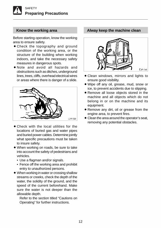
Know the working area
Before starting operation, know the workingarea to ensure safety.¡Check the topography and ground
condition of the working area, or thestructure of the building when workingindoors, and take the necessary safetymeasures in dangerous spots.
¡Note and avoid all hazards andobstructions such as ditches, undergroundlines, trees, cliffs, overhead electrical wiresor areas where there is danger of a slide.
¡Check with the local utilities for thelocations of buried gas and water pipesand buried power cables. Determine jointlywhat specific precautions must be takento insure safety.
¡When working on roads, be sure to takeinto account the safety of pedestrians andvehicles.• Use a flagman and/or signals.• Fence off the working area and prohibit
entry to unauthorized persons.¡When working in water or crossing shallow
streams or creeks, check the depth of thewater, the solidity of the ground, and thespeed of the current beforehand. Makesure the water is not deeper than theallowable depth.
Refer to the section titled “Cautions onOperating” for further instructions.
Alway keep the machine clean
¡Clean windows, mirrors and lights toensure good visibility.
¡Wipe off any oil, grease, mud, snow orice, to prevent accidents due to slipping.
¡Remove all loose objects stored in themachine and all objects which do notbelong in or on the machine and itsequipment.
¡Remove any dirt, oil or grease from theengine area, to prevent fires.
¡Clean the area around the operator’s seat,removing any potential obstacles.

13
SAFETY
Preparing Precautions
Perform inspection andmaintenance daily
Failure to notice or repair machineirregularities or damage can lead toaccidents.¡Before operating, perform the prescribed
inspections and make repairs immediatelyshould any irregularities be found.
¡ If a failure that causes loss of control suchas steering, service brakes or engineoccurs, stop the machine motion asquickly as possible, follow the shutdownprocedure, and keep machine securelyparked until the malfunction is corrected.

14
SAFETY
Starting Precautions
Maintain three point contactwhen mounting and dismounting
¡Do not jump on or off the machine. Neverattempt to mount or dismount a movingmachine.
¡When mounting and dismounting the cab,first open the door fully to the lockedposition and check that it does not move.(For machines with cabs)
¡Always face the access system andmaintain a three point contact with therecommended handrails and steps whilegetting on and off the machine. Keep stepsand platform clean.
¡Never use the safety lock lever or controllevers as hand holds.
Clear the area of other personsbefore starting the machine
Do not start the engine until you are sure it issafe. Before starting, check or perform thefollowing.¡Walk around the machine and warn all
personnel who may be servicing themachine or are in the machine path. Donot start until all personnel are clearly awayfrom the machine.
¡Check for any “DO NOT OPERATE” tagsor similar warning notices on the cab door,controls or starter switch.
¡Sound horn to alert everyone around themachine.
Start the engine from theoperator’s seat
¡Adjust, secure and latch the operator’sseat.
¡Fasten the seat belt.¡Check that the parking device is applied
and place all controls in the neutralposition.
¡Check that the safety lock lever is in thelock position.
¡Clear the area of all persons.¡Start and operate the engine from the
operator’s seat only.¡Never attempt to start the engine by
shorting across the starter terminals.

15
SAFETY
Starting Precautions
Starting with jumper cables
Use jumper cables only in the recommendedmanner. Improper use of jumper cables canresult in battery explosion or unexpectedmachine motion.
Refer to the section titled “If the BatteryGoes Dead” for proper instructions.
After starting the engine
After starting the engine, perform thefollowing operations and checks in a safeplace with no persons or obstacles in thearea. If any malfunctions are found, followthe shutdown procedure and report themalfunction.¡Warm up the engine and hydraulic fluid.¡Observe all gauges or warning
instruments for proper operation.¡Listen for unusual noises.¡Test engine speed control.¡Operate each control to insure proper
operation.
In cold weather
¡Be careful of slippery conditions onfreezing ground, steps and hand holds.
¡ In severe cold weather, do not touch anymetal parts of the machine with exposedflesh, as flesh can freeze to the metal andCause injury.
¡Do not use ether or starting fluids on thisengine. These starting aids can causeexplosion and serious injury or death.
¡Warm up the engine and hydraulic fluidbefore operating.

16
SAFETY
Operating Precautions
Ensure good visibility
¡When working in dark places, turn on themachine’s working lights and headlightsand/or provide extra stationary lighting ifnecessary.
¡When visibility is poor due to severeweather (fog, snow or rain), stop operatingthe machine and wait until conditionsimproves.
Do not permit riders on themachine
¡Do not allow anyone to ride on any part ofthe machine at any time while traveling.
¡Do not allow anyone to be on any part ofthe machine while operating.
Check for safety in thesurrounding area before starting
¡Understand the machine limitations.¡Use a signal person where clearances are
close or your vision is obstructed.¡Never allow anyone to enter the slewing
(swing) radius and machine path.¡Signal your intention to move by sounding
the horn.¡There are blind spots to the rear of the
machine.If necessary, swing the cab around beforebacking up to check that the area is safeand clear.

17
SAFETY
Operating Precautions
Travel safety
¡Travel with the dozer blade up, the hoeattachment folded as shown on thediagram, and the bucket raised 30 to 40cm (12 to 16 in.) from the ground.
¡Do not slew (swing) while traveling. If youmust operate the hoe attachment whiletraveling, operate at speeds slow enoughso you have complete control at all times.
¡Avoid crossing over obstacles wheneverpossible. If you must do so, keep the hoeattachment close to the ground and travelslowly. Never cross obstacles if they willseriously tilt the machine (to an angle of10° or greater).
¡On uneven ground, travel at low speedand avoid accelerating, stopping orchanging directions abruptly.
¡When roading a machine, know and usethe signaling devices required on themachine. Provide an escort for road travelwhen required.
Check the position of the under-carriage (tracks) before traveling
Before operating the travel levers, check tomake sure that the dozer blade is to the frontof the operator’s seat. BE AWARE that whenthe dozer blade is to the rear of the operator’sseat, the travel levers operate in the oppositedirection to when the dozer blade is in thefront.
Fully extend the crawler widthwhen operating
Always operate the machine with the crawlerwidth at the maximum to increase machinestability. The smaller the crawler width, thegreater the possibility the machine can tipover. If it is absolutely necessary to operatethe machine with a narrow crawler width, doso with great care.
(12 to 16 in.)
E4A040

18
SAFETY
Operating Precautions
Cautions on traveling on slopes
When traveling on slopes or grades, becareful that the machine does not tip (roll)over or slide.¡Never exceed the machine’s stability
capabilities (maximum gradeability - 25°,lateral tipping angle - 10°). Also note thatwhen actual working area conditions arepoor the machine’s stability capabilitiesmay be lower.
¡When traveling on slopes or grades, lowerthe bucket to a height of 20 to 30 cm (8 to12 in.) off the ground. In emergencies,lower the bucket to the ground and stopthe machine.
¡When traveling on slopes or grades, moveslowly in first gear (low speed).
¡Do not travel down slopes in reverse.¡On grass, dead leaves, wet metal or
frozen surfaces, the machine may slidesideways even on very gentle slopes.Make sure the machine never facessideways with respect to the slope.
¡Do not change directions or cross slopessideways. First return to a flat surface thenredirect the machine.
Operate on snow or ice with extracare
¡When traveling on snow or frozensurfaces, keep the machine travel speeddown and avoid accelerating, stopping orchanging directions abruptly.
¡Remember that the road shoulder, fences,etc., may be buried in the snow and notvisible.
¡Lower the dozer blade when parked onunsure ground conditions.

19
SAFETY
Operating Precautions
Insure driver safety beforeloading trucks
Do not load a truck unless the driver is in asafe place.¡Never swing or position the bucket over
personnel or truck cabs.¡Load the truck from the rear.
¡Maintain the maximum possible distancefrom power lines and never violate theminimum clearance.
¡Always contact the nearest electric utilityand determine jointly what specificprecautions must be taken to insure safety.
¡Consider all lines to be power lines andtreat all power lines as energized eventhough it is known or believed that thepower is shut off and the line is visiblygrounded.
¡Use a signal person to observe theapproach of any part of the machine orload to the power line.
¡Caution all ground personnel to standclear of the machine and the load at alltimes.
¡ If the machine should come in contact witha live electrical source, do not leave theoperator’s seat. Do not allow anyone toapproach or touch the machine.
¡Be especially careful of buried high voltagepower lines.
Keep a safe distance fromelectrical power lines
Never approach power lines with any part ofthe machine and its load unless all local andnational required safety precautions havebeen taken. Electrocution and death canresult from arcing, touching or even beingclose to a machine that is in contact with ornear an electrical source.

20
SAFETY
Operating Precautions
Watch out for hazardous workingconditions
¡Never undercut a high bank. Beparticularly alert for the possibility of acave-in.
¡Do not operate in places where there is adanger of falling rocks.
¡Keep machine well back from the edge ofan excavation. Avoid undercutting themachine.
¡Do not approach unstable surfaces (cliffs,road shoulders, deep trenches, etc.). Theground may give way under the machine’sweight or vibrations, causing the machineto tip over.
• The ground is weak after rain orexplosions.
• The ground is also unstable on banksand near dugout trenches.
Operating on slopes isdangerous
When operating on slopes or grades, slewing(swinging) or operating working equipmentmay cause the machine to lose stability andtip over. Avoid operating on slopes wheneverpossible.
¡Level off the work area.
¡Avoid swinging the loaded bucket in adownhill direction. This will reduce thestability of the machine.
Fill

21
SAFETY
Operating Precautions
Never slew (swing) sideways withexcessive weights
The machine can tip over more easily in thelateral direction than in the longitudinaldirection.¡Do not slew (swing) sideways with
excessive weight at the front.In particular do not slew sideways onslopes.
¡The front is heavier for machines equippedwith breakers, crushers or telescopic armsthan for machines equipped with thestandard bucket. Do not operate suchmachines sideways especially with thedigging arm (boom) downhill.
Watch boom clearance
When operating under bridges, in tunnels,near power lines or indoors, be careful notto hit the boom or arm against overheadobjects.
Excavators are not designed forlifting loads
The machine is specifically designed forexcavation work and has no safety devicesfor crane operation. Extreme caution shouldbe used if the excavator is used for lifting.¡Never lift loads in excess of capacity.
Overload will cause the machine to roll andcan result in serious injury or death.
¡All rated lift capacities are based on themachine being level and on a firmsupporting surface. For safe workingloads, the user is expected to make dueallowance for the particular job conditionssuch as soft or uneven ground, non-levelcondition, side loads, dynamic or jerkedloads, hazardous conditions, experienceof personnel, etc. The operator and otherpersonnel should fully acquaintthemselves with the operator’s manualbefore operating this machine, and rulesfor safe operation of equipment shall beadhered to at all times.
¡Failure of the bucket linkage or slingscould result if chains or slings areincorrectly attached, resulting in seriousinjury or death.
¡Do not attempt to pull stumps out of theground while using the machine as acrane. The loads imposed on the machineunder this use are completely unknown.
¡Never allow any personnel to stand on orunder lifted loads or even within themaneuvering area.

22
SAFETY
Operating Precautions
Danger of flying objects
This machine is not equipped with protectiveguards to protect the operator from flyingobjects. Do not use the machine in placeswhere there are risks of the operator beinghit by flying objects.
Cautions on Towing
When towing, selecting the wrong wire rope,inspecting improperly, or towing in the wrongway could lead to accidents resulting inserious injury or death.¡The wire rope breaking or coming
detached could be extremely dangerous.Use a wire rope suited for the requiredtowing force.
¡Do not use a wire rope that is kinked,twisted or otherwise damaged.
¡Do not apply strong loads abruptly to thewire rope.
¡Use safety gloves when handling the wirerope.
¡Make sure there is an operator on themachine being towed as well as on themachine that is towing.
¡Never tow on slopes.¡Do not let anyone near the wire rope while
towing.
N0A006

23
SAFETY
Stopping Precautions
Park safely
¡Park the machine on firm, level ground andapply the parking device.
¡When parking on streets, use barriers,caution signs, lights, etc., so that themachine can easily be seen even at nightto avoid collision with other vehicles.
¡Before leaving the machine, do thefollowing:1. Set the slew lock lever to the locked
position.2. Lower the bucket and dozer blade to
the ground.3. Raise the safety lock lever to engage
the lock.4. Stop the engine and remove the key.5. Lock the engine hood and the tool box
(option).
E3A4901

24
SAFETY
Transporting Precautions
Load and unload the machinesafely
The machine may roll or tip over or fall whileloading or unloading it. Take the followingprecautions:¡Select a firm, level surface and keep
sufficient distance from road shoulders.¡Use loading ramps of adequate strength
and size. Maintain the slope of loadingramps within 15 degrees.
¡Secure the ramps to the truck bed.¡Keep the truck bed and loading ramps
clean of oil, clay, ice, snow, and othermaterials which can become slippery.Clean the tracks.
¡Block the transport vehicle so it can notmove.
¡Use a signal person when loading andunloading the machine, and travel slowlyin first gear (low speed).
¡Never change course on the ramp.¡Do not slew (swing) on ramps. The
machine may tip over.¡When slewing (swinging) on the truck bed,
do so slowly as the footing can beunstable.
¡Engage the slew (swing) lock after loading.¡Block both tracks and secure the machine
to the truck bed with load binders.
Lifting the machine safely
¡Know and use correct crane signals.¡ Inspect the lifting equipment daily for
damaged or missing parts.¡Keep all other persons out of the area
when lifting. Do not move the machineover the heads of ther persons.
¡Do not lift the machine with an operator(s)on it.
¡When lifting, use a wire rope with sufficientstrength with respect to the machine’sweight.
¡Do not lift with the machine in a postureother than the one described in theprocedure below. Doing so is dangerousas it may result in the machine losing itsbalance.Refer to page 152 “Lifting the Machine”.
Transport the machine safely
¡Know and follow the safety rules, vehiclecode and traffic laws when transportingthe machine.
¡Consider the length, width, height andweight of the truck with the machineloaded on it when determining the bestroute.
E4F001
Fasten to the suspension fitting
Ramp
15° or lessDistance between ramps
Stopper

25
SAFETY
Maintenance Precautions
Attach a “DO NOT OPERATE” tag
Severe injury could result if an unauthorizedperson should start the engine or touchcontrols during inspection or maintenance.¡Stop the engine and remove the key
before performing maintenance.¡Attach a “DO NOT OPERATE” tag to the
starter switch or control lever.
Use the correct tools
Do not use damaged or weakened tools ortools designed for other purposes. Use toolssuited for the operation at hand.
Replace important safety partsperiodically
¡Replace fuel hoses periodically. Fuelhoses become weaker over time, even ifthey appear to be in good shape.
¡Replace important safety parts wheneveran irregularity is found, even if it is beforethe normal time for replacement.Refer to the section titled “Important Parts”for further details.
Anti-explosive lighting
Use anti-explosive electrical fixtures andlights when inspecting fuel, oil, coolant,battery fluid, etc. If lighting that is not anti-explosive should break, the substance couldignite, resulting in serious injury or death.
Do not allow unauthorizedpersonnel in the work area
Do not allow unauthorized personnel in thework area. Chips or other debris can fly offmachine parts when grinding, welding orusing a hammer.

26
SAFETY
Prepare the work area
¡Select a firm, level work area. Make surethere is adequate light and, if indoors,ventilation.
¡Clear obstacles and dangerous objects.Eliminate slippery areas.
Stop the engine beforeperforming maintenance
¡Avoid lubrication or mechanicaladjustments with the machine in motionor with the engine running while stationary.
¡ If maintenance must be performed withthe engine running, always work as a two-person team with one person ready to shutoff the engine immediately while the otherworks on the machine.• When performing maintenance, be sure
to keep your body and clothing awayfrom moving parts.
Maintenance Precautions
Always clean the machine
¡Clean the machine before performingmaintenance.
¡Stop the engine and cover electrical partswhen washing the machine. Water onelectrical parts could cause short-circuitsor malfunctions.Do not use water or steam to wash thebattery, sensors, connectors or theoperator’s seat area.
Stay clear of moving parts
¡Stay clear of all rotating and moving parts.Wrapping or entanglement may result inserious injury or death.
¡Keep hands, clothing and tools away fromthe rotating fan and running fan belts.

27
SAFETY
Securely block the machine orany component that may fall
¡Before performing maintenance or repairsunder the machine, set all workingequipment against the ground or in thelowermost position.
¡Securely block the tracks.¡ If you must work beneath the raised
machine or equipment, always use woodblocks, jack-stands or other rigid andstable supports. Never get under themachine or working equipment if they arenot sufficiently supported. This procedureis especially important when working onhydraulic cylinders.
Securely block the workingequipment
To prevent unexpected movement, securelyblock the working equipment when repairingor replacing the cutting edges or bucket teeth.
Cautions on opening the enginehood
¡Opening the engine hood while the engineis running may cause serious injury ordeath. Stop the engine before opening theengine hood.
¡Be sure to secure the engine hood whenopening it. Do not open the engine hoodon slopes or in strong wind.
Maintenance Precautions
Place heavy objects in a stableposition
When removing or installing the hoeattachment, place it in a stable position sothat it does not tip over.

28
SAFETY
Maintenance Precautions
Use caution when fueling
¡Do not smoke or permit open flames whilefueling or near fueling operations.
¡Never remove the fuel cap or refuel withthe engine running or hot. Never allow fuelto spill on hot machine components.
¡Maintain control of the fuel filler nozzlewhen filling the tank.
¡Do not fill the fuel tank to capacity. Allowroom for expansion.
¡Clean up spilled fuel immediately.¡Tighten the fuel tank cap securely. Should
the fuel cap be lost, replace it only withthe original manufacturer’s approved cap.Use of a non-approved cap without properventing may result in pressurization of thetank.
¡Never use fuel for cleaning purposes.¡Use the correct fuel grade for the operating
season.
Handling of hoses
Fuel, oil or hydraulic fluid leaks can cause afire.¡Do not twist, bend or hit the hoses.¡Never use twisted, bent or cracked hoses,
tubes and pipes. They may burst.¡Retighten loose connections.
Be careful with hot andpressurized components
Stop the engine and allow the machine tocool down before performing inspection andmaintenance.¡The engine, muffler, radiator, hydraulic
lines, sliding parts and many other partsof the machine are hot directly after theengine is stopped. Touching these partswill cause burns.
¡The engine coolant, oil and hydraulic fluidare also hot and under high pressure.Be careful when loosening caps andplugs. Working on the machine underthese conditions could result in burns orinjuries due to the hot oil spurting out.
Be careful with hot coolingsystems
Do not remove the radiator cap or drain plugswhen the coolant is hot. Stop the engine, letthe engine and radiator cool and loosen theradiator cap or drain plugs slowly.

29
SAFETY
Maintenance Precautions
Be careful with fluids underpressure
Pressure can be maintained in the hydrauliccircuit long after the engine has been shutdown.¡Release all pressure before working on
the hydraulic system.
¡Hydraulic fluid under pressure canpenetrate the skin or eyes and causeinjury, blindness or death. Fluid escapingfrom a small hole can be almost invisible.Wear a safety goggles and heavy glovesand use a piece of cardboard or wood tosearch for suspected leaks.If fluid is injected into the skin, it must beremoved within a few hours by a doctorfamiliar with this type of injury.
Release all pressure beforeworking on the hydraulic system
Oil may spurt out if caps or filters are removedor pipes disconnected before releasing thepressure in the hydraulic system.¡Gradually loosen the vent plug to relieve
tank pressure.¡Move all the control levers and pedals
several times in all directions to releasethe pressure from the working equipmentcircuitry. (For link type controls)
¡When removing plugs or screws ordisconnecting hoses, stand to the side andloosen slowly to gradually release theinternal pressure before removing.
Be careful with grease underpressure
The track adjuster contains highlypressurized grease. If the tension is adjustedwithout following the prescribed procedure,the grease discharge valve may fly off,resulting in injury.¡Do not loosen the grease nipple.¡Loosen the grease discharge valve slowly.¡Do not put your face, arms, legs or body
in front of the grease discharge valve.¡ If no grease is expelled when grease
discharge valve is loosened, there is aproblem. Contact your nearest serviceoutlet for repairs. DO NOT disassemble,as this is very dangerous.
E3A6201
30
SAFETY
Maintenance Precautions
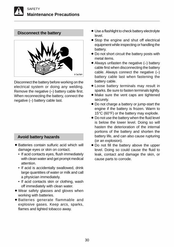
Disconnect the battery
Disconnect the battery before working on theelectrical system or doing any welding.Remove the negative (–) battery cable first.When reconnecting the battery, connect thenegative (–) battery cable last.
Avoid battery hazards
¡Batteries contain sulfuric acid which willdamage eyes or skin on contact.• If acid contacts eyes, flush immediately
with clean water and get prompt medicalattention.
• If acid is accidentally swallowed, drinklarge quantities of water or milk and calla physician immediately.
• If acid contacts skin or clothing, washoff immediately with clean water.
¡Wear safety glasses and gloves whenworking with batteries.
¡Batteries generate flammable andexplosive gases. Keep arcs, sparks,flames and lighted tobacco away.
¡Use a flashlight to check battery electrolytelevel.
¡Stop the engine and shut off electricalequipment while inspecting or handling thebattery.
¡Do not short circuit the battery posts withmetal items.
¡Always unfasten the negative (–) batterycable first when disconnecting the batterycable. Always connect the negative (–)battery cable last when fastening thebattery cable.
¡Loose battery terminals may result insparks. Be sure to fasten terminals tightly.
¡Make sure the vent caps are tightenedsecurely.
¡Do not charge a battery or jump-start theengine if the battery is frozen. Warm to15°C (60°F) or the battery may explode.
¡Do not use the battery when the fluid levelis below the lower level. Doing so willhasten the deterioration of the internalportions of the battery and shorten thebattery life, and can also cause rupturing(or an explosion).
¡Do not fill the battery above the upperlevel. Doing so could cause the fluid toleak, contact and damage the skin, orcause parts to corrode.

31
SAFETY
Maintenance Precautions
Have a Takeuchi service agentrepair welding cracks or otherdamage
Ask a Takeuchi service agent to repair anywelding problems which are detected. If notfeasible, make sure the welding is done by aqualified person in a properly equippedworkplace.
Checks after maintenance
¡Gradually raise the engine speed from alow idle to maximum speed and check thatno oil or water is leaking from servicedparts.
¡Move the controls and check that themachine is operating properly.
Disposing of wastes
¡Funnel spent fluids from the machine intocontainers. Disposing of fluids improperlydestroys the environment.
¡Follow the prescribed regulations whendisposing of oil, fuel, engine coolant,refrigerant, solvents, filters, batteries orother harmful substances.

32
SAFETY
Safety Signs (decals)
The following safety signs (decals) have been placed on your machine in the areas indicated.They are intended for the personal safety of you, and those working with you. Please takethis manual, walk around your machine and note the content and location of these safetysigns. Review these signs and the operating instructions in this manual with your machineoperators.
¡Keep the signs legible. If they are not, obtain replacements from your Service outlet.

33
SAFETY
1. No.03593-06500
3. No.03593-13700
Safety Signs (decals)
4. No.03593-07400
2. No.03393-79820 6. No.03993-00500Position of Hoisting
5. No.03593-32300
7. No.05693-21980
8. No.03593-47010
9. No.03593-47020
DO NOTenter into
swinging area
WARNING
WARNINGThis machine,if improperly operated or maintained can cause bodily harm,or evenDEATH.Read and understand the owners manualsupplied with this machine before operating.Keep all safety devices in place and functional.Do not operate the machine unless the seatbelt is properly fastened around you.Follow the instructions in the Operator’s Manual when hoisting the machine or fastening it to the transport vehicle.
03593-13700
1 -
2 -
3 -
4 -
5 -
CAUTION
03593-07400
STOP ENGINEBEFORE OPENING
03593-32300
Check what type of lever control arrangement you are operating with before beginning operations.
WARNING
WARNING
05693-21980
Engine may be HOT
WARNING
03593-47010
THIS EXCAVATORMUST NOT BE USED
AS A CRANE
WARNING
03593-47020
WHEN BUCKETS WIDER THAN STANDARDARE FITTED TO THIS MACHINE,CAB(CANOPY)DAMAGE MAY OCCUR WHENFULL LEFT HAND BOOM OFFSET IS USED.

34
SAFETY
Safety Signs (decals)
10. No.03393-68100
11. No.03393-75040
12. No.03393-75050
WARNING
03393-68100
WHEN BUCKETS WIDER THAN STANDARDARE FITTED TO THIS MACHINE,CAB(CANOPY)DAMAGE MAY OCCUR WHENFULL RIGHT HAND BOOM OFFSET IS USED.
CAUTION
03393-75040
DO NOT USE ETHERUSAGE OF ETHER FOR STARTING PURPOSES MAY CAUSE INTERNAL ENGINE DAMAGE.
CAUTION
03393-75050
HYDRAULIC TANK MUST REMAIN PRESSURIZED TO AVOID DAMAGE TO PUMPS.
14. No.03593-06700Hydraulic oil
13. No.03593-06600Diesel Fuel
Diesel Fuel Only03593-06600
D
15. No.03293-64601Noise Outside the CabThis value indicates the noise level outsidethe machine and refers to the noise perceivedby the persons who are in the vicinity of thework area.

35
Names of Components .............................. 36
Doors and Covers ...................................... 38
Seat and Seat Belt ...................................... 40
Instruments ................................................ 41
Switches ..................................................... 42
Levers and Pedals ..................................... 43
Accessories ............................................... 47
CONTROLS

36
CONTROLS
Names of Components
Upperstructure1. Canopy2. Seat3. Engine hood4. Fuel tank5. Hydraulic tank
Undercarriage 6. Crawler belt 7. Idler 8. Track roller 9. Shoe slide10. Travel motor
Working equipment11. Bucket12. Bucket cylinder13. Arm14. Arm cylinder15. Boom16. Boom cylinder17. Boom bracket18. Swing cylinder19. Auxiliary hydraulic line20. Dozer blade21. Blade cylinder
B5B001
1
10
16
13
1514
19
12
18
17
11
2
3
4
5
98
7
620 21

37
CONTROLS
1. Instruments2. Starter switch3. Horn switch4. Travel speed lever5. Selector lever6. Slew lock lever7. Safety lock lever
8. Throttle lever 9. Left operating lever10. Right operating lever11. Boom swing pedal12. Travel lever13. Auxiliary pedal14. Blade lever
Names of Components
B5B002E1
2
1311
3
7
5
14
9
7
8
6
1012 4
1

38
CONTROLS
Doors and Covers
Starter Key
The starter key is used not only to start andstop the engine, but also to lock and unlockthe following places:¡Engine hood
Engine Hood
WARNING
¡¡¡¡¡Before opening the engine hood, besure to stop the engine. If your handsor tools should get caught in the fanor fan belt while the engine is runningthey may be severed.
¡¡¡¡¡When leaving the engine hood open,be sure to lock it in place. Do not leavethe engine hood open when there is astrong wind or when on slopes.
¡¡¡¡¡When opening and closing the enginehood, be careful not to get your handsor other parts of your body caught.
Opening
1. Insert the starter key and turn itcounterclockwise to unlock the enginehood.
2. Lift the engine hood (1) fully.3. Check that the engine hood is securely
locked in place.
Closing1. Support the engine hood by hand and pull
the stay (2) to the front to unlock it.2. Close the engine hood (1) and press it
down until a click is heard at the front.
E4B003
B5B020
2
1
B5B004

39
CONTROLS
Doors and Covers
Fuel Filler Cap
WARNING
¡¡¡¡¡Do not smoke or permit open flameswhile fueling or near fuelingoperations.
¡¡¡¡¡Supply fuel in a well ventilated placeand with the engine stopped.
¡¡¡¡¡Clean up spilled fuel immediately.¡¡¡¡¡Do not fill the fuel tank to capacity.
Allow room for expansion.¡¡¡¡¡Tighten the fuel filler cap securely.
Opening and closing1. Open the engine hood.
O : Open S : Closed2. Turn the fuel filler cap (1).
Manual Case (option)
B5B021
1
SO
B5A001

40
CONTROLS
Seat and Seat Belt
Seat
WARNING
Adjust, secure and latch the operator’sseat.
Fore-and-aft adjustment
1. Pull on lever and slide the seat backwardor forward to bring it to the optimumposition for operating the machine.
2. Release the lever at the desired positionand the seat will remain fixed there.
Seat Belt
CAUTION
Always fasten the seat belt securelybefore starting the engine.
Fastening the seat belt1. Adjust the seat to the optimum position
for operating, raise your torso, and sit backfirmly into the seat.
2. Pull the seat belt to the desired length.
3. Make sure that the belt is not twisted andthen insert the tongue plate (A) into thebuckle (B) of the seat belt until you hear aclicking sound as it locks in place.
Releasing the seat belt
1. To remove the seat belt, simply press thebutton (C) located on the buckle.The seat belt is automatically stowedaway.
B5B005
E4B023B
A
E4B024
C

41
CONTROLS
Instruments
Warning Lamps
IMPORTANT: If a warning lamp lights,stop all operations immediately andinspect and maintain the appropriate part.Refer to page 131 “Troubleshooting”.
1. Battery Charge Warning LampThis lamp lights if a problemarises in the chargingsystem while the engine isrunning.
2. Engine Oil Pressure Warning LampThis lamp lights if thelubricant oil pressure dropsabnormally while the engineis running.
Meters
3. Hour MeterThis displays the totalengine running time inhours.The rightmost digit indicates
tenths of hours (6 minutes).Set the inspection and maintenance intervalsaccording to the time displayed on the hourmeter.
4. Water Temperature GaugeThis indicates thetemperature of the enginecoolant.The needle should be within
the green range during machine operation.The red range indicates overheating.
HOURS
1/10
°C1 2 3
4
B5B0061
C4B030
C4B031
C4B016
°C
B5B007

42
CONTROLS
Starter Switch
IMPORTANT: Do not repeatedly switchthe key from OFF to ON and ON to OFFover a short period. Doing so will causeengine breakdown.
PREHEAT ..... Position for preheating theengine.
OFF .............. Position for stopping theengine and inserting orremoving the key.
ON ................ Position in which the engineis running. At this position, allthe electrical equipment isfunctional.
START .......... Position for starting theengine. When the key isreleased, the switchautomatically returns to theON position.
Switches
Horn Switch
Press the switch on the right operating leverto blow the horn.
Boom Light
When the switch is depressed while thestarter switch is at ON, the light turns on oroff as follows:O ...... Off I ....... On
PREHEAT
START
ONOFF
E4B010 B5B008
IO
B5B009

43
CONTROLS
Levers and Pedals
Slew Lock Lever
WARNING
Engage the slew lock when traveling,parking or transporting the machine.
IMPORTANT: Do not try to slew when theslew lock lever is set to the lockedposition.
Use this lever to lock the upperstructure sothat it cannot slew.¡Turn the lever forward to unlock.¡When setting to the locked position,
always line up the upperstructure andundercarriage and turn the lever backwardto lock.
¡ If the upperstructure and undercarriageare not lined up, slewing will not be lockedeven if the lever is set to the lockedposition.
Safety Lock Lever
WARNING
¡¡¡¡¡Before leaving the operator’s seat,raise the safety lock lever to engagethe lock and stop the engine.If any controls should be touchedaccidentally when the safety lock leveris lowered, the machine will movesuddenly, and cause serious injury ordeath.
¡¡¡¡¡Note that the dozer blade, boom swingand auxiliary hydraulics controls arenot locked, even when the safety locklever is set to the lock position. Do nottouch these controls accidentally.
¡¡¡¡¡Be careful not to touch the operatinglevers when raising and lowering thesafety lock lever.
This device is for locking the hoe attachment,slewing and traveling.When the safty lock lever is raised, theoperating and travel levers are locked.
B5B022
B5B010

44
CONTROLS
Throttle Lever
This controls the engine speed.(A) .... Low idling(B) .... Maximum speed
Operating Levers
WARNING
¡¡¡¡¡Be careful to check which pattern oflever control arrangement you areoperating with before beginningoperations.
¡¡¡¡¡The explanations in this manual are forthe ISO pattern.
Use these levers to operate the boom, arm,bucket and upperstructure (slew).Refer to pages 56, 57 “Lever Pattern”.Refer to page 64 “Operating the WorkingEquipment”.
Blade Lever
Use this lever to operate the dozer blade andswitch the crawler width.(A) .... Blade up/narrow crawler width(B) .... Blade down/wide crawler widthTo change the crawler width, press theselector lever in before operating it.Refer to page 60 “Changing the Crawler Width”.
Travel Levers
WARNING
Before operating the travel levers, checkto make sure that the dozer blade is tothe front of the operator’s seat. BEAWARE that when the dozer blade is tothe rear of the operator’s seat, the travellevers operate in the opposite directionto when the dozer blade is in the front.
Use these levers to move forward andbackward and to change directions.Refer to page 61 “Operating the Travel Levers”.
Levers and Pedals
A
B
B5B011 B5B013
AB
B5B012
B5B015

45
CONTROLS
Travel Speed Lever
CAUTION
It is not possible to change directionswhen traveling in 2nd (high) speed. Tochange directions, first release the travelspeed lever to uncouple the travel levers.
The travel speed lever switches the machinetravel speed.(1) ..... 1st (low) speed(2) ..... 2nd (high) speedIn 2nd speed, the left and right travel leversare coupled so only straight travel is possible.
Boom Swing Pedal
Use this pedal to operate the boom swing.(A) .... Boom swing right(B) .... Boom swing left
Auxiliary Pedal
This pedal controls the flow of the oil in theauxiliary hydraulic circuit.(A) .... Hydraulic oil flows to left auxiliary
hose(B) .... Hydraulic oil flows to right auxiliary
hose
Levers and Pedals
B5B017
A
B
1
2
B5B0161
B5B018
B
A

46
CONTROLS
Levers and Pedals
Pedal Stopper
This is a device for fixing the auxiliary pedalto the operating status so that when usingwith a hand breaker, etc., connected to theauxiliary ports, the hand breaker can beturned on and off using it’s own switch.1. Lift the pedal and press on the heel side
(A).2. Put the bolt (1) through the hole in the
pedal to lock it.
Selector Lever
Use this lever when changing the crawlerwidth. This lever switches the operation ofthe blade and span cylinder.1. To change the crawler width, move this
lever to the right (S).2. Move the blade lever and change the
crawler width.
B5B019A
1
B S
B5B0231

47
CONTROLS
Accessories
Auxiliary Hydraulic Lines
WARNING
Oil may spurt out if caps or filters areremoved or pipes disconnected beforereleasing the pressure in the hydraulicsystem.¡¡¡¡¡When removing plugs or
disconnecting hoses, release theinternal pressure before removing.
These lines deliver the hydraulic oilnecessary for operating a hydraulic breaker,crusher or other attachments.
Stop valve .....S : Closed O : Open
Connecting the Hydraulic CircuitsTo connect the attachment hydraulic lines,use the following procedures:1. Move the auxiliary pedal several times to
relieve pressure on the lines.2. Make sure the stop valves are closed.3. Remove the plugs.4. Connect the attachment hydraulic lines to
ports (a) and (b).5. Open the stop valves.6. When connecting is complete, purge air
from the hydraulic lines.a. Start and run the engine at low idle with
no load for 10 minutes.b. With the engine running at low idle
operate the auxiliary pedal repeatedly(approx. 10 times) to purge air from thehydraulic lines.
c. Stop the engine and wait for more than5 minutes until bubbles escape from thehydraulic oil in the tank.
IMPORTANT: Follow the procedures forpurging air as instructed by theattachment manufacturer if specified todo so.
7. Check for leaks.
Before dismantling the attachment, move theauxiliary pedal several times to relievepressure on the lines and be sure to closethe stop valves.
b
a
S O
B5C004
B5D023
B
A

48
CONTROLS
Accessories
External Power Socket (for EU)
WARNING
Only use applicable electric products withthis socket.
Use this socket as an external power supply.To use, raise the cap (1).
B5C007
1

49
CONTROLS
Accessories
The operating pattern of the left and right operating levers can be changed.
WARNING
Be careful to check which pattern of lever control arrangement you are operating withbefore beginning operations.
Switching the Lever Pattern
(A) : ISO pattern(G) : JCB pattern1. Remove the lower mount section of the
boots and turn them upwards.2. Loosen the bolts and remove the cover.
3. Switch rod (2) to plate (3).4. Switch rod (4) to plate (5).5. Set the boots and cover back as they
were.6. Check the lever pattern.
ISO
A
JCB
G
C4L004

50

51
Before Starting Operation ......................... 52
Starting and Stopping the Engine ............. 53
Machine Operation..................................... 56
Operating Procedures ............................... 67
Parking the Machine .................................. 75
Handling in Cold Weather .......................... 76
Handling Rubber Crawlers ........................ 77
OPERATION

52
OPERATION
Before Starting Operation
Mounting and Dismounting
WARNING
¡¡¡¡¡Do not jump on or off the machine.Never attempt to mount or dismount amoving machine.
¡¡¡¡¡When mounting and dismounting thecab, first open the door fully to thelocked position and check that it doesnot move. (For machines with cabs)
¡¡¡¡¡Always face the access system andmaintain a three point contact with therecommended handrails and stepswhile getting on and off the machine.Keep steps and platform clean.
¡¡¡¡¡Never use the safety lock lever orcontrol levers as hand holds.
Walk-Around Inspection
Perform the walk-around inspections beforestarting the engine the first time that day.Perform the inspections as described under“Maintenance - Walk-Around Inspection”(pages 95 and 96).
Daily Inspection
Perform the daily inspections once a daybefore starting the engine the first time thatday.Perform the inspections as described under“Maintenance - Daily Inspection” (pages 97to 101).
B5D0011

53
OPERATION
Starting and Stopping the Engine
Before Starting the Engine
1. Adjust the seat for a comfortable operatingposition.
2. Fasten your seatbelt.
3. Check that the safety lock lever is in thelocked position.
4. Check that all the levers and pedals arein the neutral position.
5. Insert the key into the starter switch, turnit to the ON position, then perform thefollowing inspection:
¡The battery charge warning lamp (1)and engine oil pressure warning lamp(2) light, and the meters also startfunctioning.
If a lamp does not light, the bulb may be burntout or a wire may be damaged. Contact aTakeuchi sales or service outlet for repairs.
HOURS
1/10
°C1 2
B5D0032
B5B003
B5D002
PREHEATOFF
ON
START
E4D002

54
OPERATION
Starting and Stopping the Engine
Starting the Engine
WARNING
¡¡¡¡¡Clear the area of all persons.¡¡¡¡¡Sound horn to alert everyone around
the machine.
IMPORTANT: Do not run the starter motorfor more than 15 consecutive seconds. Ifthe engine fails to start, wait for 30seconds to protect the battery, and thentry again to start the engine.
Normal Starting
1. Pull the throttle lever to the middle position.
2. Turn the key to the START position andstart the engine.
3. Once the engine starts, release the key.The key automatically returns to the ONposition.
4. Return the throttle lever.5. Check that the warning lamps are off.6. Warm up the engine.
Refer to page 55 “Warming Up the Engine”.
Starting in Cold Weather
1. Pull the throttle lever to the middle speedposition.
2. Turn the key to the PREHEAT position andhold it there about 3 seconds.
3. Turn the key to the START position andstart the engine.
4. Once the engine starts, release the key.The key automatically returns to the ONposition.
5. Return the throttle lever.6. Check that the warning lamps are off.7. Warm up the engine.
Refer to page 55 “Warming Up theEngine”.
B5D004
PREHEAT
START
OFFON
E4D005
PREHEATOFF
ON
START
E4D060
B5D004

55
OPERATION
Starting and Stopping the Engine
Warming Up the Engine
IMPORTANT: Avoid racing the engineuntil it is warmed up.Do not warm up the engine for longperiods of time (20 minutes or more).
1. Return the throttle lever, then idle theengine and run it for about 5 minutes withno load.
Stopping the Engine
IMPORTANT: Do not stop the enginesuddenly when operating with heavyloads or at maximum speed. Doing somay cause the engine to overheat orseize. Never bring the engine to a suddenstop except in the case of a trueemergency.
1. Idle the engine for about 5 minutes togradually let it cool.
2. Turn the key to the OFF position to stopthe engine.
B5D006
B5D007
PREHEATOFF
ON
START
E4D007

56
OPERATION
Machine Operation
Lever Pattern (ISO Pattern)
WARNING
¡¡¡¡¡Be careful to check which pattern of lever control arrangement you are operatingwith before beginning operations.
¡¡¡¡¡The explanations in this manual are for the ISO pattern.
B5D008
Left Crawler Forward
Left Crawler Reverse
Arm Out
Arm In
Upperstructure Slew Left
Upperstructure Slew Right
Boom Swing Left
Boom Swing Right
Right Crawler Forward
Right Crawler Reverse
Boom Lower
Boom Raise
Bucket Load
Bucket Dump
Dozer Blade Lower
Dozer Blade Raise
⟨⟨⟨⟨⟨ISO⟩⟩⟩⟩⟩

57
OPERATION
Machine Operation
Lever Pattern (JCB Pattern)
WARNING
¡¡¡¡¡Be careful to check which pattern of lever control arrangement you are operatingwith before beginning operations.
¡¡¡¡¡The explanations in this manual are for the ISO pattern.
Left Crawler Forward
Left Crawler Reverse
Boom Lower
Boom Raise
Upperstructure Slew Left
Upperstructure Slew Right
Boom Swing Left
Boom Swing Right
Right Crawler Forward
Right Crawler Reverse
Arm Out
Arm In
Bucket Load
Bucket Dump
Dozer Blade Lower
Dozer Blade Raise
B5D016
⟨⟨⟨⟨⟨JCB⟩⟩⟩⟩⟩

58
OPERATION
Machine Operation
Warming Up the Machine(Hydraulic Oil)
WARNING
Operating the working equipment withoutwarming up the machine (hydraulic oil)is dangerous, as response will be slowand the equipment may move inunexpected ways. Be sure to sufficientlywarm up the machine.
IMPORTANT: Do not operate the leverssuddenly when the hydraulic oiltemperature is below 20°C (68°F). Theproper hydraulic oil temperature duringoperation is 50 to 80°C (122 to 176°F), butif operations must be performed at lowertemperatures, heat up the hydraulic oilto at least 20°C (68°F).
Normal Warm-up
1. Pull the throttle lever to the middle position,then run the engine at medium speed forabout 5 minutes with no load.
2. Fully lower the safety lock lever todisengage the lock and lift the bucket fromthe ground.
3. Extend and retract each of the cylindersseveral times with no load.
4. Set the slew lock lever to the releasedposition before starting to slew.
B5D004
G4D005
B5D009
B5B024

59
OPERATION
Machine Operation
5. Slew slowly left and right several times.
6. Travel slowly forward and backwardseveral times.
Warming Up in Cold Weather1. Perform the normal warm-up procedure.
Refer to the previous page.
2. Set the bucket cylinder at the stroke endand keep it there.Do not do this for more than 30 seconds.
3. Repeat step 2 until the bucket operatingspeed is normal.
Inspection After Warm-up
After warming up the engine and hydraulicoil, perform the checks and inspectionsdescribed below, and repair if there is aproblem.
1. Check that the warning lamps and metersare as follows:¡Are all the warning lamps off?¡ Is the water temperature gauge’s
needle within the green range?2. Check that there are no irregularities in
the exhaust color, sound and vibrations.
3. Raise the safety lock lever to engage thelock and check that the operating andtravel levers are locked.E4D011
HOURS
1/10
°C
B5D0101
B5B003

60
OPERATION
Machine Operation
Changing the Crawler Width
WARNING
Always operate the machine with thecrawler width at the maximum to increasemachine stability. The smaller the crawlerwidth, the greater the possibility themachine can tip over. If it is absolutelynecessary to operate the machine with anarrow crawler width, do so with greatcare.
Perform these operations on a flat, solidsurface with no obstacles in the way.
1. Lift the machine body using the hoeattachment and dozer blade.
IMPORTANT: Always lift the body beforechanging the crawler width. Failure to doso can result in damage to the trackframes and spanner cylinder.
2. Move the selector lever to the right (S).
3. Push the blade lever forward to extendcrawler width.¡a900mm (35.4 in.)If necessary, also replace the blade’splates and use the dozer blade with theextended width.
4. Pull the blade lever backward to retractcrawler width.¡a680mm (26.8 in.)
C4D016
B5B014
B S
B5D011
N
B5D012
N

61
OPERATION
Machine Operation
Changing the Dozer blade width
1. Pull out the lock pins (1).
2.Turn the plate (2).3.Secure the plate (2) with the lock pins (1).
21
B5D013
12
B5D014
Operating the Travel Levers
WARNING
¡¡¡¡¡Never allow anyone to enter theslewing (swing) radius and machinepath.
¡¡¡¡¡Signal your intention to move bysounding the horn.
¡¡¡¡¡There are blind spots to the rear of themachine.If necessary, slew the cab aroundbefore backing up to check that thearea is safe and clear.
¡¡¡¡¡Before operating the travel levers, checkto make sure that the dozer blade is tothe front of the operator’s seat. BEAWARE that when the dozer blade is tothe rear of the operator’s seat, the travellevers operate in the opposite directionto when the dozer blade is in the front.
¡¡¡¡¡Remove any obstacles in themachine’s path.
Traveling Forward and Backward
1. Pull the throttle lever and increase theengine speed.
2. Lower the safety lock lever to the releasedposition.
B5D005
B5D009

62
OPERATION
Machine Operation
3. Fold the hoe attachment and lower it to30 to 40 cm(12 to 16 in.) above the ground.
4. Lift the dozer blade.5. Operate the left and right travel levers as
described below.
When the dozer blade is in front of theoperator’s seat:aTo move forward:
Tilt the levers forward.eTo move backward:
Tilt the levers backward.
When the dozer blade is behind theoperator’s seat:aTo move forward:
Tilt the levers backward.eTo move backward:
Tilt the levers forward.
Traveling in 2nd (High) Speed
CAUTION
It is not possible to change directionswhen traveling in 2nd (high) speed. Tochange directions, first release the travelspeed lever to uncouple the travel levers.
1. Tilt the travel speed lever fully to the leftand grasp the right travel lever with thesame hand.
2. Tilt the levers forward or backward to travelstraight in 2nd speed.
3. Release the travel speed lever to returnto 1st (low) speed.
Pivot Turn
Turning to the left when stopped:aTo turn forward to the left:
Tilt the right lever forward.eTo turn backward to the left:
Tilt the right lever backward.To turn to the right, operate the left lever inthe same way.
30~40cmE4D014
E4D015
Neutral Neutral
E4D016
Neutral Neutral
1
2
B5D0241
E4D017
Neutral

63
OPERATION
Machine Operation
Turning to the left while traveling:aTo turn left while traveling forward:
Set the left lever to neutral.eTo turn left while traveling backward:
Set the left lever to neutral.To turn to the right while traveling, operatethe right lever in the same way.
Spin Turn
aTo spin left:Tilt the left lever backward and the rightlever forward.
eTo spin right:Tilt the right lever backward and the leftlever forward.
Stopping Travel
WARNING
¡¡¡¡¡Park the machine on firm, level groundand apply the parking device. If youmust park on a slope or incline, blockthe machine securely to preventmovement.
¡¡¡¡¡ If any controls should be touchedaccidentally when the safety lock leveris lowered, the machine will movesuddenly, and cause serious injury ordeath.
¡¡¡¡¡Note that the dozer blade, boom swingand auxiliary hydraulics controls arenot locked, even when the safety locklever is set to the lock position. Do nottouch these controls accidentally.
CAUTION
Never bring the machine to a sudden stopexcept in the case of a true emergency.Stop as gently as possible.
1. Slowly set the left and right travel leversto the neutral position. The machine stops.
E4D018
Neutral
E4D019
Neutral
E4D020
NeutralNeutral

64
OPERATION
Machine Operation
Operating the WorkingEquipment
WARNING
¡¡¡¡¡Be careful to check which pattern oflever control arrangement you areoperating with before beginningoperations.
¡¡¡¡¡The explanations in this manual are forthe ISO pattern.
Use the right operating lever to operate theboom and bucket.Use the left operating lever to operate thearm and for slewing.Return the operating levers to the neutralposition to stop the hoe attachments.
1. Set the safety lock lever to the releasedposition.
2. Set the slew lock lever to the releasedposition.
3. Set the pedals to the level position.
Slewing
WARNING
Check the surrounding area for safetybefore slewing.
aTo slew left:Tilt the left operating lever to the left.
eTo slew right:Tilt the left operating lever to the right.
Operating the Boom
aTo lower the boom:Tilt the right operating lever forward.
eTo raise the boom:Tilt the right operating lever backward.
B5D002
B5D017
B5D018

65
OPERATION
Machine Operation
Operating the Arm
aTo contract the arm:Tilt the left operating lever backward.
eTo extend the arm:Tilt the left operating lever forward.
Operating the Bucket
aTo dig:Tilt the right operating lever to the left.
eTo dump:Tilt the right operating lever to the right.
Operating the Boom Swing
aTo swing left:Press the toe side of the pedal.
eTo swing right:Press the heel side of the pedal.
Operating the Dozer Blade
aTo lower the dozer blade:Tilt the lever forward.
eTo raise the dozer blade:Tilt the lever backward.
B5D019
B5D020
B5D015
B5D021

66
OPERATION
Machine Operation
Operating the AuxiliaryHydraulics
Use this to operate a breaker, crusher orother attachment.
When the pedal is pressed, hydraulic oil isdelivered to the auxiliary hose’s ports (a) and(b).aTo deliver hydraulic oil to port (a):
Press the heel side (A) of the pedal.eTo deliver hydraulic oil to port (b):
Press the toe side (B) of the pedal.Refer to page 47 “Auxiliary Hydraulic Lines”.
b
a
S O
B5C004
B5D023
B
A

67
OPERATION
Operating Procedures
Prohibited Operations
WARNING
¡¡¡¡¡Do not operate on base rock (hard orsoft).
¡¡¡¡¡Do not slew (swing) while traveling. Ifyou must operate the hoe attachmentwhile traveling, operate at speeds slowenough so you have complete controlat all times.
Do not perform breaking or levelingoperations using slew force
Do not break down walls or level groundusing slew force. Also, do not dig the bucketteeth into the ground during slewing. Doingso will damage the hoe attachment.
Do not Dig while Traveling
Do not dig the bucket into the ground anduse the traveling force to dig.
Be Gentle on the Hydraulic Cylinders
Do not extend the hydraulic cylinders to thestroke ends. Operate them with leeway.
Do not support the machine body with thehoe attachment as it is lowering with the armcylinder fully extended. Doing soconcentrates the load on the arm cylinderand could damage the arm cylinder.
Do not Drive Piles with the Bucket or Digwith it Using Shock Force
Doing so will shorten the service life of thehoe attachment. Use hydraulic force to dig.
E4D029
E4D030
E4D031
E4D032

68
OPERATION
Operating Procedures
Do not Perform Operations Using theMachine’s Dropping Force
Putting excessive strain on the machine willshorten its service life. Use the hydraulicforce of the cylinders and always dig withshallow, long strokes.
Digging Base Rock
For hard base rock, break the rock up intosmall pieces with a breaker, etc., beforedigging. This prevents damage to themachine and is thus more economical in theend.
Caution on Exposing the Dozer Blade toShocks
Hitting the dozer blade against rocks, etc.,could damage the dozer blade or the bladecylinder.
Caution on Folding the Hoe Attachment
Be careful not to hit the bucket or dozer bladewhen folding the hoe attachment.
Do not use the Dozer Blade as an Outrigger
E4D033
E4D034
E4D040
E4D041
N0D009

69
OPERATION
E4A040
Operating Procedures
Pay Attention to the Dozer Blade whenDigging
When digging deeply with the dozer bladepositioned at the front, be careful that theboom cylinder and bucket do not hit the dozerblade.Operate with the dozer blade at the rearwhenever possible.
Caution on Digging Down with the DozerBlade
This dozer blade is designed for simple earthpushing. Do not dig down deeply with thedozer blade. Doing so could damage thedozer blade and lower body.
Cautions on Operating
Cautions on Traveling
Traveling over obstacles (rocks, stumps, etc.)may subject the body to strong shocks andresult in damage. Avoid traveling overobstacles whenever possible. If you must doso, keep the hoe attachment near the ground,travel at low speed, and go over the obstacleat the center of the crawler.
Cautions on Traveling in 2nd (High)Speed
On uneven ground, travel at low speed andavoid accelerating, stopping or changingdirections abruptly.Also, when traveling in 2nd speed, do so withthe dozer blade at the front.
E4D044
E4D037
E4D0431

70
OPERATION
Operating Procedures
Cautions on Use in Water
If you leave water at a sharp angle, the rearof the machine may be submerged, exposingthe radiator fan to water and damaging them.Do not let the rear of the machine getsubmerged.
¡Allowable water depthIn water, only use the machine up to adepth at which the water comes up to themiddle of the shoe slide (1).
¡When greasing places used under waterfor long periods of time, apply enoughgrease so that the old grease is expelled.
¡Never submerge the slew bearing or mainbody in water or sand. If the slew bearingor main body should get submerged,contact a Takeuchi sales or service outletfor inspection.
Cautions on Traveling on Slopes
WARNING
¡¡¡¡¡Never exceed the machine’s stabilitycapabilities (maximum gradeability -25°, lateral tipping angle - 10°). Alsonote that when actual working areaconditions are poor the machine’sstability capabilities may be lower.
¡¡¡¡¡When traveling on slopes or grades,lower the bucket to a height of 20 to 30cm (8 to 12 in.) off the ground. Inemergencies, lower the bucket to theground and stop the machine.
¡¡¡¡¡When traveling on slopes or grades,move slowly in first gear (low speed).
¡¡¡¡¡Do not travel down slopes in reverse.
¡¡¡¡¡Do not change directions or crossslopes sideways. First return to a flatsurface then redirect the machine.
¡¡¡¡¡On grass, dead leaves, wet metal orfrozen surfaces, the machine may slidesideways even on very gentle slopes.Make sure the machine never facessideways with respect to the slope.
E4D038
C4D014
1

71
OPERATION
Operating Procedures
Traveling PostureTraveling up slopes
When traveling up slopes at an angle of 15°or greater, travel in the posture shown in thediagram above.
Traveling down slopes
When traveling down slopes at an angle of15° or greater, lower the engine speed andtravel in the posture shown in the diagramabove.
Braking when traveling down slopes
When traveling down slopes, the brakes areapplied automatically when the travel leversare returned to the neutral position.
If the crawlers slip
If the crawlers slip while traveling up a slope,use the pulling force of the arm to climb theslope.
If the engine stops
If the engine stops when traveling down aslope, set the travel levers to the neutralposition, stop the machine, then start theengine.
E4D045E
Braking
E4D046
Climbing
Descending
E4D047E

72
OPERATION
Operating Procedures
Getting Out of Mud
If the machine gets stuck in mud, use theprocedure below to get it out.
If one crawler is stuck
1. Slew the bucket to the side which is stuck.2. Set the arm and boom to an angle of 90
to 110°.3. Press the bottom of the bucket (not the
teeth) against the ground.4. Place a plank, etc., under the lifted crawler.5. Lift the bucket and slowly move out of the
mud.
If both crawlers are stuck1. Perform steps 1 to 4 above for both
crawlers.2. Dig the bucket into the ground in front of
the machine.3. Pull with the arm and travel forward
simultaneously to slowly move out of themud.
E4D048
Do not open the door while traveling onslopes
Opening the door while traveling on slopesis dangerous, as the force required to openand close the door changes abruptly. Alwayskeep the door closed when traveling onslopes.

73
OPERATION
Operating Procedures
Operations Possible with thisMachine
Excavating
1. Set the dozer blade on the side oppositethe side you want to dig on.
2. Use the arm and bucket and dig withshallow, long strokes. The digging forceis strongest when the boom and arm angleis 80 to 120°. Use this angle for effectivedigging.
Digging Ditches
Mount a bucket suited for digging ditches andset the crawlers parallel to the ditch to bedug for greater efficiency.When digging wide ditches, dig the sides first,the center later.
Digging Side Ditches
Use the offset function to dig side ditches asshown in the diagram.
Loading
When loading dirt in a truck, starting fromthe back of the truck’s bed makes for easierloading and increases the amount of dirt thatcan be loaded.Also, use a small slewing angle for greaterefficiency.
E4D051
B5D022
E4D0501
80 ~120

74
OPERATION
Operating Procedures
Leveling
1. Bring the hoe attachment close to thebody.
2. Gradually remove the dirt from the side ofthe mound.
3. Once the mound is low, remove the dirtfrom the top. If the load on the body is tooheavy, adjust by raising or lowering thedozer blade.
E4D053

75
OPERATION
Parking the Machine
Parking
WARNING
¡¡¡¡¡Park the machine on firm, level groundand apply the parking device.
¡¡¡¡¡Before leaving the operator’s seat,raise the safety lock lever to engagethe lock and stop the engine. If anycontrols should be touchedaccidentally when the safety lock leveris lowered, the machine will movesuddenly, and cause serious injury ordeath.
1. Set the left and right travel levers to theneutral position.
2. Return the throttle lever and idle theengine at low speed.
3. Set the slew lock lever to the lockedposition.
4. Lower the bucket and dozer blade to theground.
5. Raise the safety lock lever to engage thelock.
6. Stop the engine and remove the key.Refer to page 55 “Stopping the Engine”.
Inspection and Checks AfterStopping the Engine
1. Check for oil and water leakage andinspect the working equipment, coversand lower body. If any irregularities arefound, repair.
2. Fill the fuel tank.Refer to page 99 “Checking the FuelLevel”.
3. Remove any paper scraps or dirt from theengine room.
4. Remove any mud from the lower body.
LockingBe sure to lock the following places:
¡Engine hood
E3A4901

76
OPERATION
Handling in Cold Weather
Preparing for Cold Weather
In cold weather, it may be difficult to start theengine and the coolant may freeze. Makethe preparations described below.
Changing the Fuel and LubricantChange the fuel, hydraulic oil and engine oilto types suited for cold conditions.Refer to page 88 “Fuel and Lubricant Chart”.
Engine Coolant
WARNING
The coolant is combustible. Keep flamesaway.
Use long-life coolant (antifreeze) and tapwater for the engine coolant.Supplement: New machines are deliveredwith JIS Type 2 long-life coolant (antifreeze)at a concentration of 50%.Refer to page 88 “Fuel and Lubricant Chart”.
BatteryAs the temperature drops, the batteryperformance decreases.Inspect the battery. If the charge is low,contact a Takeuchi sales or service outlet tohave the battery charged.Refer to page 107 “Inspecting the BatteryFluid Level and Replenishing”.
Cautions after CompletingOperations
Heed the following in order to prevent dirt,water, or other objects stuck on the machineas well as the lower body from freezing:¡Remove any dirt or water from the body.
In particular, water droplets on thehydraulic cylinder rod surfaces couldfreeze, and if dirt enters into the sealsalong with this, the seals could break.
¡Park the machine on a dry, hard surface.If no appropriate place can be found, putboards down and park the machine onthem.
¡Drain any water from the fuel tank toprevent freezing.Refer to page 108 “Draining the Fuel Tank”.
¡To prevent decreased batteryperformance, place a cover over thebattery or remove it from the machine andstore it in a warm place.Also add battery fluid before starting thenext morning. If battery fluid is added aftercompleting operations, the distilled watermay not mix, resulting in freezing.
After Cold Weather is Over
Perform the following after cold weather isover:¡Change the fuel and the oils for the
different devices with those specified onthe Fuel and Lubricant Chart.Refer to page 88 “Fuel and LubricantChart”.
¡When using one-season type antifreezecoolant, completely drain the antifreezecoolant, carefully clean the inside of thecoolant system, then add tap water.Refer to page 114 “Cleaning the EngineCooling System”.

77
OPERATION
Handling Rubber Crawlers
Rubber crawlers have an inherent weaknessdue to their use of rubber. Be sure to heedthe prohibitions and cautions below so as toprevent damage to the crawlers and crawlerslippage.
Prohibited Actions
Do not travel or operate the machine in thefollowing places:
¡Traveling or slewing on broken stone,jagged base rock, iron rods, iron scrapsor the edges of iron sheets may damageor cut the crawlers.
¡Traveling on riverbeds or places with manysoft rocks may cause the crawlers to slipoff or be damaged due to rocks gettingstuck in them.
¡Do not use on the seashore. The salt maycorrode the metal cores.
¡Do not let fuel, oil, salt or chemical solventsget on the crawlers. These substancesmay corrode the couplings of the crawlers’metal cores, resulting in rust or peeling. Ifthese substances should get on thecrawlers, wipe them off immediately usingwater.
¡Traveling on roads directly after asphaltingor on hot surfaces such as over fires oron iron sheets under strong sunlight mayresult in irregular wear or damage of thelugs.
¡Do not move earth in places where therubber crawlers may slip. Doing so mayspeed up lug wear.
E4D056
E4D055
E4D057
E4D058

78
OPERATION
Handling Rubber Crawlers
Cautions
Heed the following cautions when operatingthe machine:
¡Do not turn the undercarriage with the frontof the machine body lifted using the hoeattachment and the upperstructure left inthis posture. Doing so will twist the crawlerwith the load concentrated on a singlepoint on the crawler belt, rapidly leadingto damage.
¡Avoid changing course abruptly andspinning on concrete surfaces wheneverpossible.Doing so may wear or damage the rubbercrawlers.
¡Avoid drops that may expose the rubbercrawlers to strong shocks.
¡Salt, potassium chloride, ammoniumsulfate, potassium sulfate, and triplesuperphosphate of lime can damage thecrawler belts. If any of these substancesshould get on the crawler belts, wash themoff thoroughly with water.
¡Do not let the sides of the rubber crawlersrub against concrete or walls.
¡Do not damage the rubber crawlers byhitting the bucket against them.
¡Be especially careful in the winter onsnowy or frozen surfaces as the crawlerbelts tend to slip.
¡Use rubber crawler belts at temperaturesbetween -25°C to +55°C (-14°F to 131°F).
¡When storing the rubber crawlers for longperiods of time (3 months or more), do soindoors in a place not exposed to directsunlight or rain.
¡Rubber crawler belts are not as stable assteel crawler belts since the entire lug isrubber. Be very careful when slewing andswinging sideways.
Preventing the Rubber Crawlers fromSlipping OffHeed the following in order to prevent therubber crawlers from slipping off:¡Always keep the crawlers at the proper
tension.
¡When traveling up large cobblestone orrock steps (20 cm (8 in.) or greater), climbup the step at a direct angle and do notchange course on top of the step.
L4D013

79
OPERATION
Handling Rubber Crawlers
¡When climbing in reverse, do not changecourse at the point where the slope starts.
¡Avoid traveling with one crawler on a slopeor projecting object and the other crawleron a flat surface (with the machine at a tiltof 10° or greater). Travel with both crawlerson flat surfaces.
¡Do not change directions when the crawlerbelts are slack as shown in the diagram.

80

81
TRANSPORT
Loading and Unloading ............................. 82
Securing the Machine ................................ 83
Cautions on Transporting.......................... 84

82
TRANSPORT
Loading and Unloading
WARNING
The machine may roll or tip over or fallwhile loading or unloading it. Take thefollowing precautions:¡¡¡¡¡Select a firm, level surface and keep
sufficient distance from roadshoulders.
¡¡¡¡¡Use loading ramps of adequatestrength and size. Maintain the slopeof loading ramps within 15 degrees.
¡¡¡¡¡Keep the truck bed and loading rampsclean of oil, clay, ice, snow, and othermaterials which can become slippery.Clean the tracks.
¡¡¡¡¡Never change course on the ramp.¡¡¡¡¡Do not slew (swing) on ramps. The
machine may tip over.¡¡¡¡¡When slewing (swinging) on the truck
bed, do so slowly as the footing canbe unstable.
When loading or unloading the machine, besure to use ramps and following theprocedure below.
1. Apply the truck’s parking brake and placestoppers against its tires.
2. Fasten the ramps securely to the truck bedso that they will not come off. Set theramps to an angle of 15° or less.
3. Line up the center of the truck bed withthe center of the machine and the centerof the ramps with the center of thecrawlers.
4. Make sure the dozer blade does not hitthe ramps.
5. Lower the hoe attachment as much aspossible, making sure it will not hit thetruck.
6. Lower the engine speed with the throttlelever.
7. Determine the direction on the ramps, thenslowly travel up or down the ramps in 1stspeed (low speed), following the signalsof a flagman.
8. Load the machine properly at theprescribed position on the bed.Refer to page 83 “Transporting Posture”.
E4F001
Fasten to the suspension fitting
Ramp
15° or lessDistance between ramps
Stopper

83
TRANSPORT
Securing the Machine
After loading the machine in the designatedposition, secure it as described below.Transporting Posture
1. Lower the dozer blade.2. Set the slew lock lever to the locked
position.3. Fully extend the bucket and arm cylinders,
then lower the boom.4. Stop the engine and remove the starter
key.5. Raise the safety lock lever to engage the
lock.6. Set stoppers in front and behind the
crawlers.7. Put a chain or wire rope over the lower
frame and fasten it securely to preventsideways slippage.
8. Secure the bucket with a chain or wirerope.
IMPORTANT: Place a wooden blockunder the bucket so that it is not damagedby hitting the floor.
E4F002
Wire rope Padding

84
TRANSPORT
Cautions on Transporting
WARNING
¡¡¡¡¡Know and follow the safety rules,vehicle code and traffic laws whentransporting the machine.
¡¡¡¡¡Consider the length, width, height andweight of the truck with the machineloaded on it when determining the bestroute.
85
MAINTENANCE
General ....................................................... 86
Service Data ............................................... 88
Important Parts .......................................... 92
Maintenance Chart ..................................... 93
Walk-Around Inspection ............................ 95
Daily Inspection (Every 10 Hours) ............. 97
After First 50 Hours(New Machines Only) ...................... 102
Every 50 Hours ......................................... 105
Every 100 Hours ....................................... 109
After First 250 Hours(New Machines Only) ...................... 110
Every 250 Hours ....................................... 111
Every 500 Hours ....................................... 113
Every 1000 Hours ..................................... 114
Every 2000 Hours ..................................... 117
When Required ........................................ 119
Long-term Storage ................................... 124

86
MAINTENANCE
General
Maintenance Description
For long-term use of the machine under goodconditions, perform the inspection andmaintenance procedures properly and safelyas recommended in this manual.
The inspection and maintenance items aredivided according to the machine’s totaloperating time (inspection and maintenanceto be performed every 10 hours (walk-aroundand daily inspection), every 50 hours, every250 hours, etc.). Refer to the hour meter todetermine when it is time to performinspection and maintenance. Items for whichit is not possible to determine the inspectionand maintenance interval are included under“When Required”.
When operating the machine in extremelyharsh environments (with high dust levels orhigh temperatures), inspection andmaintenance should be performed earlierthan the times indicated on the MaintenanceChart.
Cautions on Maintenance
Do not perform inspection and maintenanceprocedures not prescribed in this manual.Have inspection and maintenanceprocedures not prescribed in this manualperformed by a Takeuchi sales or serviceoutlet.
Always keep the machine clean.¡Always keep the machine clean, and wash
it before performing inspection andmaintenance.
¡When washing the machine with water,stop the engine and cover the electricalsystem with plastic to protect it from water.Exposing the electrical system to water isdangerous and could result in short-circuits or malfunction. Do not wash thebattery, sensors, connectors or the insideof the cab with water or steam.
Fuel, lubricant and grease¡For fuels, lubricant and grease, follow the
instructions on the “Fuel and LubricantChart”.
¡Use pure fuels, lubricants and greaseswhich do not contain water, and be carefulto keep dirt out when changing orreplenishing fuel, lubricant or grease.
¡Store fuels, lubricants and greases in theprescribed places and in such a way thatno water or dirt can get in them.
Cautions on fueling¡ If the port includes a strainer, do not
remove the strainer when fueling.¡After fueling, be sure to securely tighten
the cap, etc.¡Do not add more than the prescribed
amount of fuel.

87
MAINTENANCE
Do not clean parts with fuel.Do not use fuel to clean parts. Use a non-combustible cleaning agent.
Keep dirt out.When mounting and removing parts, do soin a place where there is no dust, clean theworking area and the part, and keep dirt out.
Clean mounting surfaces.When mounting and removing parts, be surethat the surfaces of contact of the parts areclean. If the sealing grooves of the surfaceof contact are damaged, consult a Takeuchisales or service outlet.
Seals and split pins¡Replace removed seals and split pins with
new ones.¡When mounting, be careful not to damage
or twist the seal.
Sealing tape
¡When wrapping sealing tape aroundplugs, etc., remove any old sealing tapefrom the threads and clean the threads.
¡Wrap the sealing tape tight, leaving 1 or 2threads at the tip free.
Disposing of wastes¡Collect spent fluids from the machine in
containers. Disposing of wastesirresponsibly damages the environment.
¡Dispose of oil, fuel, cooling water, coolant,filters, batteries and other harmfulsubstances as prescribed by law.
Check after maintenance¡Gradually increase the engine speed from
a low idle to maximum speed and checkthat there is no oil or water leaking fromserviced parts.
¡Operate all the operating levers and checkthat the machine is operating properly.
Cautions on handling of battery cables¡Disconnect the battery cables (+,-) before
working on the electrical system or doingany welding.Remove the negative (-) battery cable first.When reconnecting the battery, connectthe negative (-) battery cable last.
¡Do not disconnect the battery cables whilethe engine is running. Doing so coulddamage the electronic circuitry of thealternator and other parts.
Sealing tape
Leave 1 or 2 threads free
General
E4G001

88
MAINTENANCE
Service Data
Fuel and Lubricant Chart
Use different fuels, lubricants and greases according to the temperature, referring to thechart below.¡Change the lubricant earlier than as shown in the table if it is extremely dirty or its
performance has deteriorated severely.¡Whenever possible, use the same brand of lubricant as before. If changing with a different
brand, replace the entire quantity – do not mix different brands.
* For water, use tap water (soft). Do not use well or river water.** When the ambient temperature drops below 0°C, add coolant (antifreeze). Follow the
coolant manufacturer’s instructions to determine the mixture ratio.
Part TypeType by temperature
-22 -4 14 32 50 68 86 104°F-30 -20 -10 0 10 20 30 40 °C
Replacementinterval
Capacity R(US. qt.)
Engine oilpan
Dieselengine oilAPI - CD
After first 50hrs.Every 250 hrs.
Upper limit:1.7 (1.8)
Lower limit:1.0 (1.1)
System: 14(3.7 U.S.gal)
Tank: 7.3(1.9 U.S.gal)
Hydraulictank
Antiwearhydraulic oil
Every 2000 hrs.
Use a clean, Quality fuel for good performance and optimum engine life.¡ To prevent fuel flow problems in cold weather, use diesel fuel with a pour point of
at least -12°C (10°F) below the lowest expected ambient temperature.¡ Minimum cetane number is 45. Low temperature or high altitude operation may
require the use of fuel with a higher cetane number.
Fuel tank Diesel fuelTank: 8(2.1 U.S.gal)
Enginecoolingsystem
Coolant(water * +coolant **)
Every 1000 hrs. 2.8 (3.0)
SAE 5W-20 SAE 10W-30 SAE 15W-40
Travelreductiongear
Gear oilAPI-GL-4
SAE 90After first 250hrs.Every 1000 hrs.
0.33 (0.35)each
Slew motorpinionSlewbearingWorkingequipment
Levers
LithiumbasedgreaseEP-2NLGI No. 2
Every 50 hrs.
Every 50 hrs.
Daily or every10 hrs.
When required
Asrequired
ISO VG32 ISO VG46
ISO VG68
50% coolant mixture 30% coolant mixture

89
MAINTENANCE
Expendables
Replace expendables such as filters and elements periodically, referring to the table below.
Replace the hydraulic oil regularly!
¡When using a hydraulic breaker, the oil deteriorates quicker than during normal digging.Be sure to replace the hydraulic oil and return filter element.• Failure to replace these in time can lead to damage to the machine and breaker’s hydraulic
systems. In order to improve the service life of the hydraulic systems, be sure to replacethe hydraulic oil and return filter element after the number of hours shown on the diagrambelow.
• Clean the suction strainer when changing the return filter element.
Replacement Interval (Hours)
Item Hydraulic Oil Filter Element
1st time 25
2nd time 100
Periodically 600 200
Service Data
Item Part name Part No. Replacement interval
Return filter Cartridge After first 50 hrs.Every 500 hrs.
15510-20310
Fuel filter Every 500 hrs.Element 119810-55650
After first 50 hrs.Every 250 hrs.
119305-35151Engine oil filter Cartridge
Every 1000 hrs. orafter 6 cleanings(whichever comesfirst)
Air cleaner Element(outer)
119655-12560
Every 1000 hrs. orafter 3 cleanings ofthe outer element(whichever comesfirst)
Inner Element(option)
19111-01342
When the breaker operating ratio is 100%Refer to page 154 “Hydraulic Breaker”.

90
MAINTENANCE
Service Data
Tools
Part nameNo. Part No. Remarks
1 Grease gun 16910-60600 600cc
2 Drain connector 15545-12201
3 Case 16919-00001
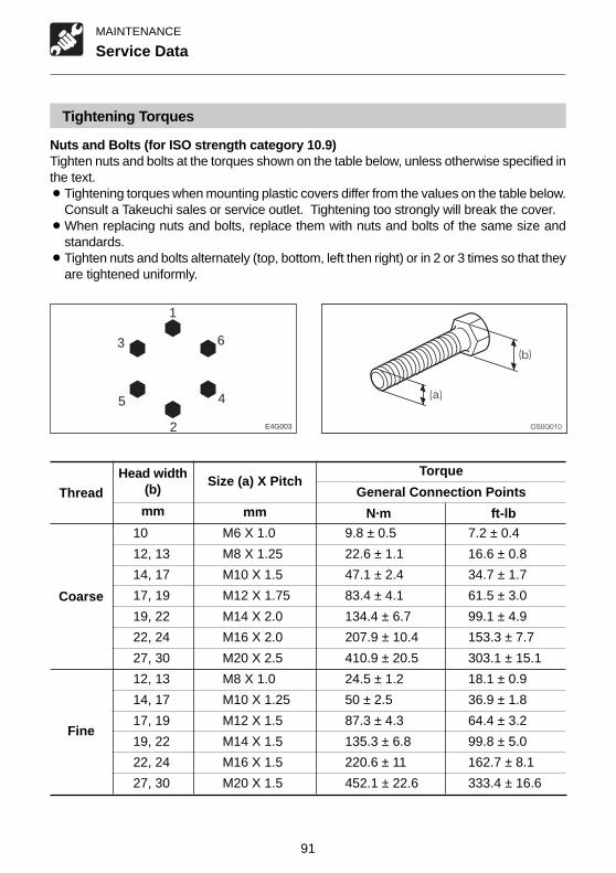
91
MAINTENANCE
Tightening Torques
Nuts and Bolts (for ISO strength category 10.9)Tighten nuts and bolts at the torques shown on the table below, unless otherwise specified inthe text.¡Tightening torques when mounting plastic covers differ from the values on the table below.
Consult a Takeuchi sales or service outlet. Tightening too strongly will break the cover.¡When replacing nuts and bolts, replace them with nuts and bolts of the same size and
standards.¡Tighten nuts and bolts alternately (top, bottom, left then right) or in 2 or 3 times so that they
are tightened uniformly.
Service Data
ThreadHead width
(b)Size (a) X Pitch
Torque
General Connection Points
N·m ft-lb
Coarse
Fine
10 M6 X 1.0 9.8 ± 0.5 7.2 ± 0.4
12, 13 M8 X 1.25 22.6 ± 1.1 16.6 ± 0.8
14, 17 M10 X 1.5 47.1 ± 2.4 34.7 ± 1.7
17, 19 M12 X 1.75 83.4 ± 4.1 61.5 ± 3.0
19, 22 M14 X 2.0 134.4 ± 6.7 99.1 ± 4.9
22, 24 M16 X 2.0 207.9 ± 10.4 153.3 ± 7.7
27, 30 M20 X 2.5 410.9 ± 20.5 303.1 ± 15.1
12, 13 M8 X 1.0 24.5 ± 1.2 18.1 ± 0.9
14, 17 M10 X 1.25 50 ± 2.5 36.9 ± 1.8
17, 19 M12 X 1.5 87.3 ± 4.3 64.4 ± 3.2
19, 22 M14 X 1.5 135.3 ± 6.8 99.8 ± 5.0
22, 24 M16 X 1.5 220.6 ± 11 162.7 ± 8.1
27, 30 M20 X 1.5 452.1 ± 22.6 333.4 ± 16.6
mmmm
E4G003
1
6
4
2
5
3

92
MAINTENANCE
Important Parts
For safe use, the machine must be serviced periodically. To increase safety, periodicallyreplace the parts listed in the following table of important parts.Serious injury or a fire could result if they deteriorate or are damaged.
Table of Important Parts
Above important parts are vulnerable to aging and wear or deterioration and it is difficult todetermine the degree to which they have deteriorated on the occasion of periodic service. Tomaintain their proper function at all times, therefore, replace them with new ones after usingthem for a specific period of time even if no abnormality is found with the parts. If you findabnormalities in these parts before their scheduled replacement time is reached, repair orreplace them immediately. If a hose clamp is deformed or cracked, replace it immediately.When replacing the important parts, please contact a Takeuchi sales or service outlet .
Also check the hydraulic hoses other than the above important parts. If any abnormality isfound in them, retighten them or replace them immediately.When replacing the hydraulic hoses, replace the O-rings and seals at the same time.
Check the fuel and hydraulic hoses according to the periodic schedule described below.Refer to “Maintenance”.
Type of inspection Inspection itemDaily inspection Leakages from joints, hydraulic or fuel hoses.Monthly inspection Leakages from joints, hydraulic or fuel hoses.
Damaged hydraulic or fuel hoses(cracks, wear and tear).Annual inspection Leakages from joints, hydraulic or fuel hoses.
Deteriorated, twisted, damaged hydraulic or fuel hoses (cracks, wearand tear) or hoses in contact with other parts of the machine.
Unit Important parts to be replaced periodically Replacement Interval
Fuel hoses
Packing in fuel filler cap
Hydraulic hoses ( Pump - delivery )
Hydraulic hoses ( Pump - suction )
Hydraulic hoses ( Slew motor )
Hydraulic hoses ( Travel motor )
Hydraulic hoses ( Boom cylinder lines )
Hydraulic hoses ( Arm cylinder lines)
Hydraulic hoses ( Bucket cylinder lines )
Hydraulic hoses ( Swing cylinder )
Hydraulic hoses ( Blade cylinder )
Hydraulic hoses ( Spanner cylinder )
Hydraulic hoses ( Auxiliary lines )
Seat belt
Workingequipment
Fuel system
Mainbody
Every 2 years
Every 3 years
Hydraulicsystem

93
MAINTENANCE
Maintenance Chart
Maintenance Items See page
Walk-Around Inspection
Inspecting by opening the engine hood 95
Inspecting by walking around the machine 96
Inspecting while sitting in the operator’s seat 96
Daily Inspection (Every 10 Hours)
Inspecting and replenishing the coolant 97
Inspecting and replenishing the engine oil 98
Inspecting the water separator 99
Checking the fuel level 99
Inspecting the hydraulic oil level and replenishing 100
Lubricating the working equipment 101
After First 50 Hours (New Machines Only)
Replacing the hydraulic oil return filter 102
Replacing the engine oil and oil filter 103
Inspecting and adjusting the fan belt 104
Every 50 Hours
Inspecting and adjusting the crawler tension 105
Lubricating the slew bearing 106
Lubricating the slew motor pinion 107
Inspecting the battery fluid level and replenishing 107
Draining the fuel tank 108
Every 100 Hours
Cleaning the fuel filter 109
Cleaning the water separator 109
After First 250 Hours (New Machines Only)
Replacing the travel motor gear oil 110

94
MAINTENANCE
Maintenance Chart
Maintenance Items See page
Every 250 Hours
Cleaning the air cleaner 111
Cleaning the radiator fins 112
Replacing the engine oil and oil filter 112
Inspecting and adjusting the fan belt 112
Every 500 Hours
Replacing the fuel filter 113
Replacing the hydraulic oil return filter 113
Every 1000 Hours
Cleaning the engine cooling system 114
Replacing the air cleaner element 115
Replacing the travel motor gear oil 116
Inspecting and adjusting the engine valve clearance 116
Retightening the engine cylinder head bolts 116
Inspecting the engine fuel injection pressure and spray condition 116
Every 2000 Hours
Replacing the hydraulic oil and cleaning the suction strainer 117
Inspecting the engine fuel injection timing 118
Inspecting the engine fuel injection valve 118
When Required
Replacing the bucket 119
Inspecting the rubber crawlers 121
Replacing the rubber crawlers 122
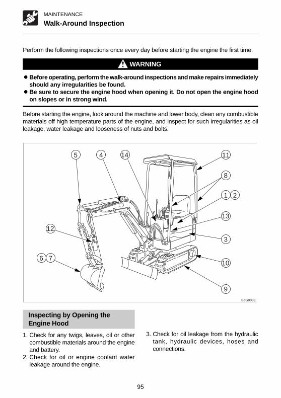
95
MAINTENANCE
Perform the following inspections once every day before starting the engine the first time.
WARNING
¡¡¡¡¡Before operating, perform the walk-around inspections and make repairs immediatelyshould any irregularities be found.
¡¡¡¡¡Be sure to secure the engine hood when opening it. Do not open the engine hoodon slopes or in strong wind.
Before starting the engine, look around the machine and lower body, clean any combustiblematerials off high temperature parts of the engine, and inspect for such irregularities as oilleakage, water leakage and looseness of nuts and bolts.
Inspecting by Opening theEngine Hood
1. Check for any twigs, leaves, oil or othercombustible materials around the engineand battery.
2. Check for oil or engine coolant waterleakage around the engine.
3. Check for oil leakage from the hydraulictank, hydraulic devices, hoses andconnections.
Walk-Around Inspection
1
B5G003E
8
76
45
3
9
2
11
13
12
14
10

96
MAINTENANCE
Walk-Around Inspection
Inspecting by Walking Aroundthe Machine
4. Check lights for dirt, damage and burntout bulbs.
5. Check attachments and hoses fordamage.
6. Check the bucket, bucket teeth and sidecutter for wear, damage and looseness.
7. Check the hook, slip stopper and hookmount of buckets with hooks for damage.(Option)
8. Check the handrail and step for damageand loose bolts.
9. Check the crawler, shoe slide, track roller,idler and sprocket for damage, wear andloose bolts.
10. Check for oil leakage from the travelmotor.
11. Check the canopy, cab and guard fordamage and loose nuts and bolts.
12. Check the labels for dirt and damage.
Inspecting While Sitting in theOperator’s Seat
13. Check the operator’s seat for dirt, oil orother combustible materials.
14. Check the monitor, instruments andswitches for dirt or damage.

97
MAINTENANCE
Daily Inspection (Every 10 Hours)
Inspecting and Replenishing theCoolant
WARNING
Do not remove the radiator cap or drainplugs when the coolant is hot. Stop theengine, let the engine and radiator cooland loosen the radiator cap or drain plugsslowly.
Inspection
1. Open the engine hood.2. Place a cloth over the radiator cap (1) and
loosen it gradually to release the internalpressure before removing it.
3. Inspect the coolant level in the radiator.• The coolant level must be 30 mm (1.2 in.)
above the top surface of the radiator core.• If the coolant level is low, add coolant.
Perform the following inspections once every day before starting the engine the first time.
WARNING
¡¡¡¡¡Before operating, perform the Daily inspections and make repairs immediately shouldany irregularities be found.
¡¡¡¡¡Be sure to secure the engine hood when opening it. Do not open the engine hoodon slopes or in strong wind.
Replenishing1. Add coolant to a level of 30 mm (1.2 in.)
above the top surface of the radiator core.2. Install the radiator cap (1).

98
MAINTENANCE
Daily Inspection (Every 10 Hours)
Inspecting and Replenishing theEngine Oil
WARNING
Stop the engine and allow the machineto cool down before performinginspection and maintenance.
Inspection
1. Open the engine hood.2. Pull out the dipstick (1) and wipe off the
oil with a rag.3. Fully reinsert the dipstick (1), then pull it
back out.4. Check the oil on the dipstick (1).
The level must be between the upper limit(H) and lower limit (L).If it is below the lower limit (L), replenish.
Replenishing
1. Remove the oil supply cap (2).2. Add oil up to the upper limit (H) of the
dipstick (1).Problems could arise if the oil level is eithertoo low or too high.
3. Tighten the oil supply cap (2).4. Start the engine, run it at low idle for about
3 minutes, then stop it.5. After about 10 minutes, inspect the oil
level.

99
MAINTENANCE
Daily Inspection (Every 10 Hours)
Inspecting the Water Separator
WARNING
Stop the engine and allow the machineto cool down before performinginspection and maintenance.
1. Open the engine hood.2. Inspect the water separator (1).
If the red indicator ring (6) is sunk to thebottom of the case (4), no water is mixedin.If the red indicator ring (6) is floating, thereis water up to the bottom of the ring. Drainthe water and clean.Refer to page 109 “Cleaning the WaterSeparator”.
Checking the Fuel Level
WARNING
¡¡¡¡¡Do not smoke or permit open flameswhile fueling or near fueling operations.
¡¡¡¡¡Stop the engine in a well-ventilatedplace when adding fuel.
¡¡¡¡¡Clean up spilled fuel immediately.¡¡¡¡¡Do not fill the fuel tank to capacity.
Allow room for expansion.¡¡¡¡¡Tighten the fuel filler cap securely.
1. Check the fuel level using the sight gauge(3).
2. If the level is low, add fuel from the fuelport (1) while watching the sight gauge (3).Refer to page 39 “Fuel Filler Cap”.
1
23
B5G008

100
MAINTENANCE
Inspecting the Hydraulic Oil Leveland Replenishing
WARNING
Oil may spurt out if caps or filters areremoved or pipes disconnected beforereleasing the pressure in the hydraulicsystem.¡¡¡¡¡Gradually loosen the vent plug to
relieve tank pressure.
InspectionThe oil level changes according to the oiltemperature. Inspect the oil level in thehydraulic oil level inspection posture shownin the diagram.¡Hydraulic oil level inspection posture
1. Start the engine and run it at low speed.2. Fully retract the arm and bucket cylinders
and ground the bucket.3. Ground the dozer blade, then stop the
engine.4. Open the engine hood.5. Inspect the oil level using the sight gauge
(2).¡When the oil temperature is about 20°C
(68°F):The level should be at the middle of thesight gauge.If it is below the middle, replenish.
Daily Inspection (Every 10 Hours)
Replenishing
1. Slowly turn the vent plug (1) to releasethe internal pressure, then remove.
2. Add hydraulic oil up to the middle of thesight gauge (2).
3. Pressurize the hydraulic tank using theprocedure next.
Pressurizing the hydraulic tank1. Start the engine and run it at low speed.2. With the vent plug (1) removed, set the
safety lock lever to the released position.
¡Hydraulic tank pressurization posture
3. Fully extend the bucket, arm, boom andswing cylinders.
4. Stop the engine and set the safety locklever to the locked position.
5. Tighten the vent plug (1).
B5G010
2
3 1

101
MAINTENANCE
Daily Inspection (Every 10 Hours)
Lubricating the Working Equipment
1. Set the machine to the lubrication posture shown in the diagram above, ground the workingequipment, then stop the engine.
2. Use the grease gun to lubricate the grease nipples.3. Wipe off the expelled grease.
B5G0112

102
MAINTENANCE
After First 50 Hours (New Machines Only)
Replacing the Hydraulic OilReturn Filter
WARNING
¡¡¡¡¡Stop the engine and allow the machineto cool down before performingmaintenance.• The engine, hydraulic lines and many
other parts of the machine are hotdirectly after the engine is stopped.Touching these parts will causeburns.
• The hydraulic fluid is also hot andunder high pressure.Be careful when loosening caps andplugs. Working on the machine underthese conditions could result inburns or injuries due to the hot oilspurting out.
¡¡¡¡¡Oil may spurt out if caps or filters areremoved or pipes disconnected beforereleasing the pressure in the hydraulicsystem.• Gradually loosen the vent plug to
relieve tank pressure.• When removing plugs or screws or
disconnecting hoses, stand to theside and loosen slowly to graduallyrelease the internal pressure beforeremoving.
1. Open the engine hood.2. Slowly turn the vent plug (1) to relieve tank
pressure, then remove.
B5G010
2
3 1
3. Using a filter wrench, turn the filter (3)counterclockwise and remove it.
4. Clean the surface of installation of the filterstand.
5. Apply a thin layer of oil to the packing ofthe new filter.
6. Install the new filter by hand.7. Tighten 3/4 more turns with the filter
wrench after the filter packing comes incontact with the surface of installation.
8. Inspect the level with the sight gauge (2),and replenish if the level is low.Refer to page 100 “Inspecting theHydraulic Oil Level and Replenishing”.
9. Pressurize the hydraulic tank.Refer to page 100 “Pressurizing theHydraulic Tank”.

103
MAINTENANCE
After First 50 Hours (New Machines Only)
Replacing the Engine Oil and OilFilter
WARNING
Stop the engine and allow the machineto cool down before performingmaintenance.¡¡¡¡¡The engine, muffler, radiator and many
other parts of the machine are hotdirectly after the engine is stopped.Touching these parts will cause burns.
¡¡¡¡¡The engine oil is also hot.Be careful when loosening caps andplugs. Working on the machine underthese conditions could result in burns.
1. Open the engine hood.2. Remove the oil supply cap (2).
3. Place a pan for catching the spent oilunder the drain plug (3).
4. Remove cap (A), install connector (B) anddrain the oil. (The oil comes out when thescrew is tightened.)
5. Remove connector (B) and install cap (A).
IMPORTANT: Check the spent oil. If itcontains large amounts of metal powder,consult a Takeuchi sales or service outlet.
6.Using a filter wrench, turn the filter (4)counterclockwise and remove it.
7.Clean the surface of installation of the filterstand.
8.Apply a thin layer of oil to the packing ofthe new filter.
9. Install the new filter by hand.10. Tighten 3/4 more turns with the filter
wrench after the filter packing comes incontact with the surface of installation.
11. Add oil up to the upper limit (H) of thedipstick (1). Problems could arise if theoil level is either too low or too high.
12. Tighten the oil supply cap (2).13. Start the engine, run it at low idle for about
3 minutes, then stop it.14. After about 10 minutes, inspect the oil
level.
B5G013AB
3
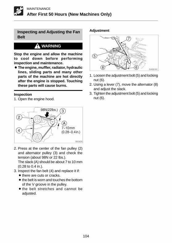
104
MAINTENANCE
After First 50 Hours (New Machines Only)
Inspecting and Adjusting the FanBelt
WARNING
Stop the engine and allow the machineto cool down before performinginspection and maintenance.¡¡¡¡¡The engine, muffler, radiator, hydraulic
lines, sliding parts and many otherparts of the machine are hot directlyafter the engine is stopped. Touchingthese parts will cause burns.
Inspection1. Open the engine hood.
2. Press at the center of the fan pulley (2)and alternator pulley (3) and check thetension (about 98N or 22 lbs.).The slack (A) should be about 7 to 10 mm(0.28 to 0.4 in.).
3. Inspect the fan belt (4) and replace it if:¡ there are cuts or cracks.¡ the belt is worn and touches the bottom
of the V groove in the pulley.¡ the belt stretches and cannot be
adjusted.
Adjustment
1. Loosen the adjustment bolt (5) and lockingnut (6).
2. Using a lever (7), move the alternator (8)and adjust the slack.
3. Tighten the adjustment bolt (5) and lockingnut (6).

105
MAINTENANCE
Every 50 Hours
Inspecting and Adjusting theCrawler Tension
WARNING
¡¡¡¡¡ If you must work beneath the raisedmachine or equipment, always usewood blocks, jack-stands or other rigidand stable supports. Never get underthe machine or working equipment ifthey are not sufficiently supported.This procedure is especially importantwhen working on hydraulic cylinders.
¡¡¡¡¡The track adjuster contains highlypressurized grease. If the tension isadjusted without following theprescribed procedure, the greasedischarge valve may fly off, resultingin injury.• Do not loosen the grease nipple.• Loosen the grease discharge valve
slowly.• Do not put your face, arms, legs or
body in front of the grease dischargevalve.
• If no grease is expelled when greasedischarge valve is loosened, there is aproblem. Contact your nearest serviceoutlet for repairs. DO NOT disassemble,as this is very dangerous.
Inspection
1. For rubber crawlers, move the machineso that the “M” or “∞” mark at the couplingis at the top center of the crawler frame.
2. Use the operating devices to lift the body.Operate the levers slowly.
3. Inspect the gap (A) between the bottomsurface of the frame at the center of thecrawler frame and the top surface of thecrawler.The gap (A) should be within the followingrange:(A) Rubber crawler :
53 to 58 mm (2.1 to 2.3 in.)
AdjustmentIncreasing the tension
1. Remove the cover (1).2. Using the grease gun, insert grease
through the grease nipple (3) in the greasedischarge valve (2).
3. Inspect the crawler tension.
C4G0182
B5G024
A
B5G023
A
1 2
3
D5G025

106
MAINTENANCE
Every 50 Hours
Decreasing the tension
1. Remove the cover (1).2. Using the Spanner, slowly loosen the
grease discharge valve (2) and drain thegrease.If the grease does not drain easily, movethe machine forward or backward.
3. Tighten the grease discharge valve (2).¡Tightening torque: 177 N·m (130 ft.lb.)
Lubricating the Slew Bearing
WARNING
Do not slew while lubricating. Doing sois dangerous, as you may get caught inthe machine.
1. Stop the engine with the machine in theposture shown on the diagram above.
2. Use the grease gun to supply grease tothe grease nipple (1).
3. Start the engine, lift the bucket and slewclockwise 90°.
4. Ground the bucket and stop the engine.5. Repeat steps 2 to 4 above three times.6. Wipe off the grease expelled from the slew
bearing and grease nipple.
B5G0261
12
3
B5G014
1
E4G026

107
MAINTENANCE
Every 50 Hours
Inspecting the Battery Fluid Leveland Replenishing
DANGER
¡¡¡¡¡Do not use the battery when the fluidlevel is below the lower level. Doing sowill hasten the deterioration of theinternal portions of the battery andshorten the battery life, and can alsocause rupturing (or an explosion).
¡¡¡¡¡Batteries generate flammable andexplosive gases. Keep arcs, sparks,flames and lighted tobacco away.
¡¡¡¡¡Use a dampened cloth to clean the areaof the fluid level lines and check thefluid level. Note that if this area iscleaned with a dry cloth, staticelectricity could cause ignition orexplosion.
WARNING
¡¡¡¡¡Do not fill the battery above the upperlevel. Doing so could cause the fluidto leak, contact and damage the skin,or cause parts to corrode.
¡¡¡¡¡Batteries contain sulfuric acid whichwill damage eyes or skin on contact.• If acid contacts eyes, flush
immediately with clean water and getprompt medical attention.
• If acid is accidentally swallowed,drink large quantities of water or milkand call a physician immediately.
• If acid contacts skin or clothing, washoff immediately with clean water.
Lubricating the Slew MotorPinion
1. Stop the engine with the machine in theposture shown on the diagram above.
2. Use the grease gun to supply grease tothe grease nipple (2).
3. Wipe off the grease expelled from thegrease nipple.
B5G016
2
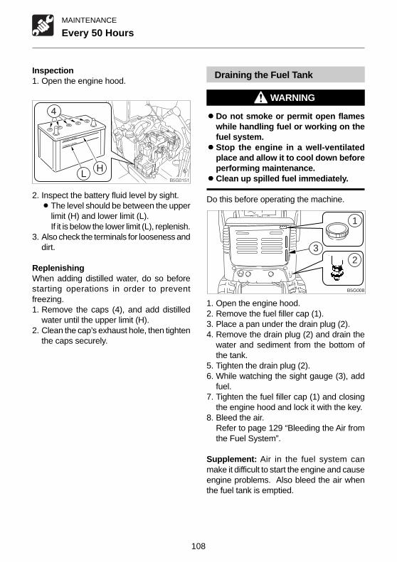
108
MAINTENANCE
Every 50 Hours
Draining the Fuel Tank
WARNING
¡¡¡¡¡Do not smoke or permit open flameswhile handling fuel or working on thefuel system.
¡¡¡¡¡Stop the engine in a well-ventilatedplace and allow it to cool down beforeperforming maintenance.
¡¡¡¡¡Clean up spilled fuel immediately.
Do this before operating the machine.
1. Open the engine hood.2. Remove the fuel filler cap (1).3. Place a pan under the drain plug (2).4. Remove the drain plug (2) and drain the
water and sediment from the bottom ofthe tank.
5. Tighten the drain plug (2).6. While watching the sight gauge (3), add
fuel.7. Tighten the fuel filler cap (1) and closing
the engine hood and lock it with the key.8. Bleed the air.
Refer to page 129 “Bleeding the Air fromthe Fuel System”.
Supplement: Air in the fuel system canmake it difficult to start the engine and causeengine problems. Also bleed the air whenthe fuel tank is emptied.
Inspection1. Open the engine hood.
2. Inspect the battery fluid level by sight.¡The level should be between the upper
limit (H) and lower limit (L).If it is below the lower limit (L), replenish.
3. Also check the terminals for looseness anddirt.
ReplenishingWhen adding distilled water, do so beforestarting operations in order to preventfreezing.1. Remove the caps (4), and add distilled
water until the upper limit (H).2. Clean the cap’s exhaust hole, then tighten
the caps securely.
1
23
B5G008

109
MAINTENANCE
Every 100 Hours
Cleaning the Fuel Filter
WARNING
¡¡¡¡¡Do not smoke or permit open flameswhile handling fuel or working on thefuel system.
¡¡¡¡¡Stop the engine in a well-ventilatedplace and allow it to cool down beforeperforming maintenance.
¡¡¡¡¡Clean up spilled fuel immediately.
1. Open the engine hood.2. Close the cock (2).3. Loosen the ring (3), then remove the case
(4) and element (5) and clean them.4. Inspect the O-ring, and if there are any
scratches or other irregularities, replaceit.
5. Assemble the case (4) and element (5)and tighten the ring (3).
6. Open the cock (2) and bleed the air.Refer to page 129 “Bleeding the Air fromthe Fuel System”.
Cleaning the Water Separator
WARNING
¡¡¡¡¡Do not smoke or permit open flameswhile handling fuel or working on thefuel system.
¡¡¡¡¡Stop the engine in a well-ventilatedplace and allow it to cool down beforeperforming maintenance.
¡¡¡¡¡Clean up spilled fuel immediately.
1. Open the engine hood.2. Close the cock (2).3. Loosen the ring (3), then remove the case
(4), element (5) and indicator ring (6) andclean them.
4. Inspect the O-ring, and if there are anyscratches or other irregularities, replaceit.
5. Assemble the indicator ring (6), case (4)and element (5) and tighten the ring (3).
6. Open the cock (2) and bleed the air.Refer to page 129 “Bleeding the Air fromthe Fuel System”.

110
MAINTENANCE
After First 250 Hours (New Machines Only)
Replacing the Travel Motor GearOil
WARNING
¡¡¡¡¡Stop the engine and allow the machineto cool down before performingmaintenance.• The travel motors are hot directly
after the engine is stopped. Touchingthem will cause burns.
• The gear oil is also hot and underhigh pressure.Be careful when loosening plugs.Working on the machine under theseconditions could result in burns orinjuries.
¡¡¡¡¡The pressure in the travel motorreduction gears case may cause oil orthe plug to fly out. Loosen the plugslowly to release the pressure.
1. Set the travel motor so that plug (2) is atthe very bottom.
2. Place a pan for catching the spent oilunder plug (2).
3. Remove plugs (1) and (2) and drain theoil.
4. Wrap new sealing tape around the plugs.5. Tighten plug (2).6. Add oil through the hole for plug (1) until
oil flows out of the hole.7. Tighten plug (1).
������
�
�

111
MAINTENANCE
Every 250 Hours
3. Loosen the clamp (1) and remove the dustcup (2).
4. Clean the inside of the dust cup (2).5. Remove the element (3).6. Cover the intake hole at the back of the
body (4) with cloth or tape to prevent dirtfrom getting in.
7. Clean the inside of the body (4).
8. Clean the element (3) with driedcompressed air {294 to 490 kPa (43 to 71psi)}.First blow the air from the inside of theelement along the flutes, then blow the airfrom the outside, and finally from the insideagain.
9. Light up the inside of the element with abulb, inspect it, and replace it if there aresmall holes or thin spots.
10. Remove the cloth or tape applied in step 6.11. Install the element (3).12. Install the dust cup (2), then fasten it with
the clamp (1).13. Fasten the body (4) with the rubber band
(5).
Cleaning the Air Cleaner
WARNING
¡¡¡¡¡Stop the engine and allow the machineto cool down before performingmaintenance.• The engine, muffler, radiator and
many other parts of the machine arehot directly after the engine isstopped. Touching these parts willcause burns.
¡¡¡¡¡Wear required appropriate equipmentsuch as safety glasses and filter maskwhen using compressed air, as metalfragments or other objects can fly andcause serious personal injury.
IMPORTANT: Be careful not to scratchthe element. Do not use an element if itis damaged.IMPORTANT: When operating themachine in very dusty places, inspectionand maintenance should be performedevery day.Supplement: Do not remove and clean theinner element (option). Replace the innerelement every 1000 hrs. or after every 3cleaning of the outer element.(whichever comes first)
1. Open the engine hood.2. Remove the hook of the rubber band (5)
and free the body (4).
B5G019
3
4
1
2 5
E4G033
E4G034

112
MAINTENANCE
Replacing the Engine Oil and OilFilter
Refer to page 103 “Replacing the Engine Oiland Oil Filter”.
Inspecting and Adjusting the FanBelt
Refer to page 104 “Inspecting and Adjustingthe Fan Belt”.
Every 250 Hours
Cleaning the Radiator Fins
WARNING
Wear required appropriate equipmentsuch as safety glasses and filter maskwhen using compressed air, as metalfragments or other objects can fly andcause serious personal injury.
IMPORTANT: Be careful not to damagethe radiator fins when cleaning them.¡¡¡¡¡When using compressed air or
pressurized water, make sure thepressure is no higher than 200kPa (28psi) and hold the nozzle sufficientlyaway from the fins.
IMPORTANT: When using water, coverthe electrical system to prevent waterfrom getting in.IMPORTANT: When operating themachine in very dusty places, inspectionand maintenance should be performedevery day.
1. Blow compressed air on the radiator finsto remove mud and dirt stuck on them.

113
MAINTENANCE
Every 500 Hours
Replacing the Fuel Filter
WARNING
¡¡¡¡¡Do not smoke or permit open flameswhile handling fuel or working on thefuel system.
¡¡¡¡¡Stop the engine in a well-ventilatedplace and allow it to cool down beforeperforming maintenance.
¡¡¡¡¡Clean up spilled fuel immediately.
1. Open the engine hood.2. Close the cock (2).3. Loosen the ring (3), then remove the case
(4) and element (5).4. Clean the case (4).5. Assemble the new element in the case
(4), then tighten the ring (3).6. Open the cock (2) and bleed the air.
Refer to page 129 “Bleeding the air fromthe fuel system”.
Replacing the Hydraulic OilReturn Filter
Refer to page 102 “Replacing the HydraulicOil Return Filter”.

114
MAINTENANCE
Every 1000 Hours
Cleaning the Engine CoolingSystem
WARNING
¡¡¡¡¡Stop the engine and allow the machineto cool down before performingmaintenance.• The engine, muffler, radiator and
many other parts of the machine arehot directly after the engine isstopped. Touching these parts willcause burns.
• The engine coolant is also hot andunder high pressure. Be carefulwhen loosening caps and plugs.Working on the machine under theseconditions could result in burns orinjuries due to the hot coolantspurting out.
¡¡¡¡¡ If maintenance must be performed withthe engine running, always work as atwo-person team with one personready to shut off the engineimmediately while the other works onthe machine.• When performing maintenance, be
sure to keep your body and clothingaway from moving parts.
¡¡¡¡¡Standing at the back of the machinewhile the engine is running is extremelydangerous, as the machine could movesuddenly. Never stand at the back ofthe machine while the engine isrunning.
¡¡¡¡¡Do not remove the radiator cap or drainplugs when the coolant is hot. Stop theengine, let the engine and radiator cooland loosen the radiator cap or drainplugs slowly.
1. Open the engine hood.
2. Place a cloth over the radiator cap (1) andloosen it gradually to release the internalpressure before removing it.
3. Place a pan for catching the spent coolantunder the drain hose (2), plug (3), thenloosen the drain hose (2), plug (3) anddrain the coolant.

115
MAINTENANCE
4. Tighten the drain hose (2), plug (3), thenadd a little cleaning agent and tap waterto the radiator until it is full. Take your timedoing this.Follow the manufacturer’s instructionswhen using the cleaning agent.
5. Run the engine at a low idle for about 30minutes. For the first 5 minutes afterstarting it, pay attention to the level of thecleaning fluid, and add tap water if the leveldrops.
6. Stop the engine and drain the cleaningfluid.
7. Tighten the drain hose (2), plug (3), addtap water, run the engine at a low idle forabout 10 minutes, then stop the engineand drain the water.Clean repeatedly until the drained wateris clear.
8. After cleaning is completed, tighten thedrain hose (2), plug (3) and add newcoolant up to the specified level.
9. Run the engine at a low idle, bleed the air,then stop the engine once the coolant levelstabilizes at the specified level.
10. Check the coolant level, then tighten theradiator cap (1).
Replacing the Air CleanerElement
WARNING
Stop the engine and allow the machineto cool down before performingmaintenance.¡¡¡¡¡The engine, muffler, radiator and many
other parts of the machine are hotdirectly after the engine is stopped.Touching these parts will cause burns.
IMPORTANT: Do not use an element if itsflutes, gaskets or seals are damaged.Supplement: Do not remove and clean theinner element (option). Replace the innerelement every 1000 hrs. or after every 3cleaning of the outer element.(whichever comes first)1. Open the engine hood.
2. Remove the hook of the rubber band (5).3. Loosen the clamp (1) and remove the dust
cup (2).4. Clean the inside of the dust cup (2).5. Remove the element (3).6. Cover the intake hole at the back of the
body (4) with cloth or tape to prevent dirtfrom getting in.
7. Clean the inside of the body (4).8. Remove the cloth or tape applied in step 6.9. Install the new element.10. Install the dust cup (2), then fasten it with
the clamp (1).11. Fasten the body (4) with the rubber band
(5).
Every 1000 Hours
B5G019
3
4
1
2 5

116
MAINTENANCE
Replacing the Travel Motor GearOil
Refer to page 110 “Replacing the TravelMotor Gear Oil”.
Inspecting and Adjusting theEngine Valve Clearance
This operation requires experience. Have itperformed by a Takeuchi sales or serviceoutlet.
Retightening the Engine CylinderHead Bolts
This operation requires experience. Have itperformed by a Takeuchi sales or serviceoutlet.
Inspecting the Engine FuelInjection Pressure and SprayCondition
This operation requires experience. Have itperformed by a Takeuchi sales or serviceoutlet.
Every 1000 Hours

117
MAINTENANCE
Every 2000 Hours
Replacing the Hydraulic Oil andCleaning the Suction Strainer
WARNING
¡¡¡¡¡Stop the engine and allow the machineto cool down before performingmaintenance.• The engine, hydraulic lines and many
other parts of the machine are hotdirectly after the engine is stopped.Touching these parts will causeburns.
• The hydraulic fluid is also hot andunder high pressure.Be careful when loosening caps andplugs. Working on the machine underthese conditions could result inburns or injuries due to the hot oilspurting out.
¡¡¡¡¡Oil may spurt out if caps or filters areremoved or pipes disconnected beforereleasing the pressure in the hydraulicsystem.• Gradually loosen the vent plug to
relieve tank pressure.• When removing plugs or screws or
disconnecting hoses, stand to theside and loosen slowly to graduallyrelease the internal pressure beforeremoving.
1. Slew 45° clockwise and set the machineto the hydraulic oil level inspection posture.Refer to page 100 “Inspecting theHydraulic Oil Level and Replenishing”.
2. Open the engine hood.
3. Loosen the bolts (4) and remove the cover(5).
4. Slowly turn the vent plug (1) to relieve tankpressure, then remove.
5. Using a filter wrench, turn the filter (3)counterclockwise and remove it.
6. Clean the surface of installation of the filterstand.
7. Apply a thin layer of oil to the packing ofthe new filter.
8. Install the new filter by hand.9. Tighten 3/4 more turns with the filter
wrench after the filter packing comes incontact with the surface of installation.
10. Place a pan for catching the spent oilunder the drain plug (6).
11. Loosen the drain plug (6) and drain thehydraulic oil.
12. Loosen the hose clip, then remove thehoses (7).
13. Remove the bolts, then remove theflange (8).
14. Remove the suction strainer (9) andclean it.
15. Clean the inside of the hydraulic tank.16. Install the suction strainer (9) to the flange
(8).
B5G0182
4
59
87
64
2
3
14
7

118
MAINTENANCE
Every 2000 Hours
17. Install the flange (8) and connect thehoses (7).
18. Tighten the drain plug (6).19. Insert hydraulic oil through the hole in the
vent plug (1), adding hydraulic oil tobetween the upper limit (H) and lowerlimit (L) of the sight gauge (2).
20. Follow the procedure under “Bleeding theair” to bleed the air from the hydraulic oilcircuit.
21. Set the machine to the hydraulic oil levelinspection posture and inspect the levelonce the temperature of the oil hasdropped.Refer to page 100 “Inspecting theHydraulic Oil Level and Replenishing”.
22. Pressurize the hydraulic tank.Refer to page 100 “Pressurizing thehydraulic tank”.
Bleeding the air
IMPORTANT: After replacing thehydraulic oil, bleed the air from thehydraulic oil circuit and hydraulicdevices. Failure to do so may damagethe hydraulic devices.
1. Start the engine and run it at low idle for10 minutes.
2. Set the engine to a low idle, then extendand retract all the cylinders 4 or 5 times,without going to the stroke end.
3. Run the engine at high speed, then extendand retract all the cylinders 4 or 5 times,without going to the stroke end.
4. Set the engine back to a low idle, thenextend and retract all the cylinders 4 or 5times to the stroke ends.
Inspecting the Engine FuelInjection Timing
This operation requires experience. Have itperformed by a Takeuchi sales or serviceoutlet.
Inspecting the Engine FuelInjection Valve
This operation requires experience. Have itperformed by a Takeuchi sales or serviceoutlet.

119
MAINTENANCE
Replacing the Bucket
WARNING
¡¡¡¡¡Before performing maintenance orrepairs under the machine, set allworking equipment against the groundor in the lowermost position.
¡¡¡¡¡ If maintenance must be performed withthe engine running, always work as atwo-person team with one personsitting in the operator’s seat while theother works on the machine.• When performing maintenance, be
sure to keep your body and clothingaway from moving parts.
¡¡¡¡¡Wear required appropriate equipmentsuch as safety glasses and filter maskwhen using hammers, as metalfragments or other objects can fly andcause serious personal injury.
¡¡¡¡¡When lining up the pin holes, alwaysdo so by sight. Your finger may be cutoff if you stick it into the hole.
Removal
1. Ground the bucket as shown on thediagram above in a stable position.
Supplement: When removing pins, set thebucket so that it is just gently against theground. If it is strongly against the ground,the resistance will be great and it will bedifficult to remove the pin.
2. Set the safety lock lever to the lockedposition and stop the engine.
3. Remove the ring of the lock pin (1) andremove the lock pin.
4. Hammer pin (2) out of the bucket.5. Remove the bucket.
Installation
1. Line up pin hole (A) in the bucket with thepin hole in the arm (5), and install the pin(2).
2. Operate the cylinder, line up pin hole (B)in the bucket with the pin hole in the linkarm (6), and install the pin (2).
When Required
E4G048
2 1
2
B5G027
E4G054
6
BA
5

120
MAINTENANCE
When Required
3. Line up the turn prevention holes, installlock pin (1), and set the ring on the innerside.
C4G032
1

121
MAINTENANCE
Inspecting the Rubber Crawlers
Repair or replace the rubber crawlers if theirconditions are as described below. Consulta Takeuchi sales or service outlet aboutrepairs or replacement.
Rubber crawlerReplace the crawler if the entire crawler isstretched and cannot be adjusted.
(1) Lug
Replace if the height of (A) is 5 mm (0.2 in.)or below.
(2) Steel cord
Replace if the steel cord is exposed over 2or more links.Replace if half or more of the steel cords onone side are cut.
When Required
(3) Metal core
Replace if even one metal core is off.
(4) Rubber
Repair if there are cracks of 60 mm (2.4 in.)or greater in length.If the steel cord is visible, repair as soon aspossible, regardless of the length of thecrack.
60 mm or greater
E4G062
3
21A
4
E4G0632
E4G0643
E4G065

122
MAINTENANCE
Replacing the Rubber Crawlers
WARNING
¡¡¡¡¡ If you must work beneath the raisedmachine or equipment, always usewood blocks, jack-stands or other rigidand stable supports. Never get underthe machine or working equipment ifthey are not sufficiently supported.This procedure is especially importantwhen working on hydraulic cylinders.
¡¡¡¡¡ If maintenance must be performed withthe engine running, always work as atwo-person team with one personsitting in the operator’s seat while theother works on the machine.• When performing maintenance, be
sure to keep your body and clothingaway from moving parts.
Removal1. Fully release the tension of the rubber
crawler.Refer to page 105 “Inspecting andAdjusting the Crawler Tension”.
2. Use the working equipment to lift the body.
3. Set an iron pipe (1) in the rubber crawlerand turn the sprocket slowly in the reversedirection.
4. Turn until the iron pipe (1) is directly nextto the idler and the rubber crawler liftsaway from the idler, then stop turning thesprocket.
5. Slide the rubber crawler sideways andremove it from the crawler frame.Remove the other rubber crawler usingthe same procedure.
Installation1. Use the working equipment to lift the body.
2. Set the rubber crawler on the sprocket.3. Set an iron pipe (1) in the rubber crawler
and turn the sprocket slowly in the reversedirection.
4. Turn until the iron pipe (1) is directly nextto the idler and the rubber crawler liftsaway from the idler, then stop turning thesprocket.
5. Slide the rubber crawler inward, engageit on the idler, then pull out the iron pipe.
Direction of rotation
Direction of rotation
When Required
E4G0671
E4G0681
E4G070

123
MAINTENANCE
6. Check that the rubber crawler is securelyengaged on the sprocket and idler.
7. Tighten the rubber crawler to the standardtension.Refer to page 105 “Inspecting andAdjusting the Crawler Tension”.
8. Install the other rubber crawler using thesame procedure.
When Required

124
MAINTENANCE
Long-term Storage
Procedures for storageIf the machine is to be stored for 30 days ormore, store it indoors. If it must be storedoutdoors, stop it on wood laid out on a flatsurface and place a waterproof cover over itso that it stays dry.1. Clean the machine.2. Inspect for oil leakage, water leakage and
loose nuts and bolts.3. Add fuel and replace the hydraulic oil and
oil.4. To prevent rusting and freezing, replace
the engine coolant with long-life coolant(LLC).Refer to page 114 “Cleaning the EngineCooling System”.
5. Use the grease gun to supply grease tothe grease nipples.
6. Fully contract the bucket and arm cylindersand ground the bucket and dozer blade.
7. Apply rust-prevention oil to the hydrauliccylinder rods.
8. Disconnect the cable from the battery’s “–”terminal and cover the battery to preventfreezing.
During storage
WARNING
¡¡¡¡¡Do not operate the engine in anenclosed area without adequateventilation.
¡¡¡¡¡ If natural ventilation is poor, installventilators, fans, exhaust extensionpipes or other artificial venting devices.
1. To prevent rusting, operate the machineonce a month so that the oil is fullycirculated.
2. Inspect the battery and recharge it ifnecessary.Have the battery charged by a Takeuchisales or service outlet.
Starting the machine after storage
IMPORTANT: If the “Procedures forstorage” have not been performed andthe machine has been stored for a longperiod of time, consult a Takeuchi salesor service outlet before reusing themachine.
1. Wipe off the rust-prevention oil that wasapplied to the hydraulic oil cylinders’ pistonrods.
2. Add fuel, oil and grease to all parts.

125
TROUBLESHOOTING
Symptoms that are not Malfunctions ...... 126
If the Engine Overheats ........................... 127
If the Battery Goes Dead.......................... 128
After the Fuel Runs Out ........................... 129
If a Fuse Blows ......................................... 130
If a Warning Lamp is illuminated ............. 131
Other Symptoms ...................................... 132
Towing ...................................................... 134

126
TROUBLESHOOTING
Symptoms that are not Malfunctions
The following symptoms are not malfunctions:
¡When the arm reaches the vertical positionwhile contracting it while the engine isrunning at low speed, the contractingspeed slows down momentarily.
¡When the bucket teeth reach thehorizontal position while the engine isrunning at low speed, the speed of bucketmovement slows down momentarily.
¡The slew motor produces noise at thebeginning and end of the slewingoperation.
¡The travel motor produces noise whenstopped suddenly during high speedtravel.
¡The control valve produces noise ifexcessive force is applied to the workingequipment and when the stroke end isreached.
¡Performance decreases when anattachment weighing more than astandard arm or bucket is mounted.
E4J001
E4J002

127
TROUBLESHOOTING
If the Engine Overheats
WARNING
¡¡¡¡¡Do not open the engine hood whenthere is steam coming from the engineroom. The steam or hot water mayspurt out, resulting in burns.
¡¡¡¡¡Do not remove the radiator cap or drainplugs when the coolant is hot. Stop theengine, let the engine and radiator cooland loosen the radiator cap or drainplugs slowly.
¡¡¡¡¡Stop the engine and allow the machineto cool down before performinginspection and maintenance.
The following symptoms indicate overheating:
¡The water temperature gauge is in the redzone.
¡The engine slows down and the forcedecreases.
¡Steam comes from the engine room.
Procedure1. Park the machine in a safe place.2. With the engine hood closed, inspect
whether steam is coming from the engineroom.
3. If there is steam, stop the engineimmediately and contact a Takeuchi salesor service outlet for repairs.If there is no steam, run the engine at lowidle and let the water temperaturedecrease.
4. Once the water temperature gauge dropsto the green zone, stop the engine.
5. Once the engine is cool, perform thefollowing inspections and procedures:¡Fan belt slack ......................... Adjust.
Refer to page 104.¡Coolant level .............................. Add.
Refer to page 97.¡Water leakage ........................ Repair.¡Radiator fins ............................ Clean.
Refer to page 112.¡Sediment in cooling system..... Clean.
Refer to page 114.If the problem persists after the aboveprocedures are taken, contact a Takeuchisales or service outlet for repairs.
HOURS
1/10
°C
B5J0011

128
TROUBLESHOOTING
If the Battery Goes Dead
The following symptoms indicate that thebattery is dead:¡The starter motor does not turn or turns
weakly, and the engine does not start.¡The horn is weak.
ProcedureUse jumper cables and start the engine usingthe rescue vehicle’s battery.
WARNING
¡¡¡¡¡Use jumper cables only in therecommended manner. Improper useof jumper cables can result in batteryexplosion or unexpected machinemotion.• Do not let the problem vehicle and
rescue vehicle touch each other.• Do not let the “+” and “–” clips of the
jumper cables touch each other.• Connect the jumper cables to the “+”
terminals first, and disconnect themfrom the “–” terminals (ground) first.
• Connect the final clip of the jumpercable to a point as far away from thebattery as possible.
¡¡¡¡¡Use safety glasses when using jumpercables to start the machine.
IMPORTANT: Use jumper cables andclips of a size suited to the battery’scapacity. Do not used damaged orcorroded jumper cables and clips.IMPORTANT: The rescue vehicle’sbattery must have the same capacity asthe problem vehicle’s battery.IMPORTANT: Connect the clips securely.
Connecting the jumper cables
IMPORTANT: Set the starter keys of boththe rescue vehicle and problem vehicleto the OFF position.
1. Connect the clip of jumper cable (R) tothe problem vehicle’s “+” terminal.
2. Connect the other clip of jumper cable (R)to the rescue vehicle’s “+” terminal.
3. Connect the clip of jumper cable (B) tothe rescue vehicle’s “–” terminal.
4. Connect the other clip of jumper cable (B)to the problem vehicle’s engine block.Connect the clip as far from the battery aspossible.
Starting the engine1. Check that the clips are securely
connected to the terminals.2. Start the rescue vehicle’s engine and run
it at high speed.3. Start the problem vehicle’s engine.
E4J005
12
34
R
B
Rescue vehicle battery Problem vehicle battery
To engine block

129
TROUBLESHOOTING
If the Battery Goes Dead After the Fuel Runs Out
Disconnecting the jumper cablesOnce the engine starts, disconnect thejumper cables following the connectionprocedure in reverse order.
1. Disconnect the clip of jumper cable (B)from the problem vehicle’s engine block.
2. Disconnect the other clip of jumper cable(B) from the rescue vehicle’s “–” terminal.
3. Disconnect the clip of jumper cable (R)from the rescue vehicle’s “+” terminal.
4. Disconnect the other clip of jumper cable(R) from the problem vehicle’s “+” terminal.
RechargingHave a Takeuchi sales or service outletrecharge batteries that have gone dead.
Bleeding the Air from the FuelSystem
1. Add fuel.2. Open the water separator and fuel filter
cocks.
3. Turn the starter key to the ON position andhold it there for about 20 seconds.The automatic air bleeder bleeds the airfrom the fuel system.
4. Start the engine and inspect for fuelleakage.
Supplement: Air in the fuel system canmake it difficult to start the engine and causeengine problems. Also bleed the air whenthe fuel tank is emptied.
TROUBLESHOOTING
E4J006
4
1
3
2
R
BFrom engine block
Rescue vehicle battery Problem vehicle battery
PREHEATOFF
ON
START
E4D002

130
TROUBLESHOOTING
If a Fuse Blows
If a light does not turn on or the electricsystem does not operate, a fuse may beblown. Inspect the fuses.
Inspecting and Replacing theFuse
WARNING
If the fuse blows as soon as it is replaced,there is a problem with the electricsystem. Continued use may lead to fire.Consult a Takeuchi sales or serviceoutlet.
1. Turn the starter key to the OFF position tostop the engine.
2. Open the fuse box (1) and inspect for anyblown fuses.
3. If a fuse is blown, replace it with a fuse ofthe same capacity.
Inspecting the Fusible Link
If the electric power is not switched on afterturning the starter switch to the ON position,the cartridge type fusible link (2) might beblown open. Open the engine hood andinspect. If the fusible link is blown, pleasecontact a Takeuchi sales or service.
Supplement: A fusible link is a large pieceof fuse wiring which is mounted in a circuitwhich carries a large electrical current. Linka regular fuse, the fusible link protects theelectrical parts and wiring from damage dueto abnormally large currents.
Fuse Layout and Circuits Protected
1
B5J004
E4J007
NormalBlown
B5J005
2
10A Horn
10A Water temperature gauge
10A Boom light
30A Stop solenoid
Capacity Protected circuit

131
TROUBLESHOOTING
If a Warning Lamp is illuminated
If a warning lamp is illuminated during operation, park the machine in a safe place and performthe procedures described below.
Warning lamp Lamp name Procedure
Battery chargewarning lamp
Engine oilpressurewarning lamp
Inspect the engine oil level. If the lamp is illuminatingeven though the level is normal or if it continuesilluminating after oil is added, consult a Takeuchi salesor service outlet.Refer to page 98 “Inspecting and Replenishing theEngine Oil”.
OSOB080
OSOB070
There is a problem with the fan belt or alternator.Inspect the fan belt for slack or breakage and adjust asnecessary. If the lamp continues illuminating aftermaintenance, there is a problem with the alternator.Consult a Takeuchi sales or service outlet.Refer to page 104 “Inspecting and Adjusting the FanBelt”.

132
TROUBLESHOOTING
Other Symptoms
For symptoms not included on the table below or if the problem persists after the properprocedures have been taken, consult a Takeuchi sales or service outlet.
Symptom Main cause Procedure
¡Safety lock lever is raisedHoe attachment,slewing or travelingoperation not possible
¡Lower the safety lock lever.Refer to page 43.
Digging force isinsufficient
¡ Insufficient hydraulic oil level
¡Hydraulic oil is not heated
¡Air cleaner is clogged
¡Hydraulic oil is not ofsuitable type
¡Replenish to the prescribedlevel.
Refer to page 100.¡Perform the warm-up
procedure.Refer to page 58.
¡Clean the air cleaner.Refer to page 111.
¡Replace the hydraulic oil.Refer to page 117.
Traveling is notpossible or not smooth
¡Stones or foreign objects arestuck
¡Remove the foreign object.
Machine does not travelstraight forward
¡Stones or foreign objects arestuck
¡Faulty crawler tensionadjustment
¡Remove the foreign object.
¡Adjust the crawler to theprescribed tension.
Refer to page 105.
Slewing is not possibleor not smooth
¡ Insufficient grease on slewbearing
¡Add grease.Refer to page 106.

133
TROUBLESHOOTING
Other Symptoms
Hydraulic oiltemperature is too high
¡ Insufficient hydraulic oil ¡Replenish to the prescribedlevel.
Refer to page 100.
Starter motor turns butengine does not start
¡ Insufficient fuel
¡Air in fuel system
¡Water in fuel system
¡Add fuel.Refer to page 99.
¡Bleed the air.Refer to page 129.
¡Drain the water.Refer to page 108.
Crawlers slip off ¡Crawlers are too loose ¡Adjust the tension.Refer to page 105.
Engine exhaust is whiteor bluish
¡Excessive engine oil
¡ Insufficient fuel
¡Adjust to the prescribedlevel.
Refer to page 98.¡Replace the fuel.
Engine exhaust isoccasionally black
¡Air cleaner is clogged ¡Clean the air cleaner.Refer to page 111.
Irregular noise isproduced from theengine (combustion ormechanical noise)
¡Low quality fuel is beingused
¡Engine is overheating
¡Damage in muffler
¡Replace the fuel.¡ If the Engine Overheats
Refer to page 127.¡Replace the muffler.
(Request at a sales orservice outlet.)
Symptom Main cause Procedure

134
TROUBLESHOOTING
Towing
WARNING
When towing, selecting the wrong wirerope, inspecting improperly, or towing inthe wrong way could lead to accidentsresulting in serious injury or death.¡¡¡¡¡The wire rope breaking or coming
detached could be extremelydangerous. Use a wire rope suited forthe required towing force.
¡¡¡¡¡Do not use a wire rope that is kinked,twisted or otherwise damaged.
¡¡¡¡¡Do not apply strong loads abruptly tothe wire rope.
¡¡¡¡¡Use safety gloves when handling thewire rope.
¡¡¡¡¡Make sure there is an operator on themachine being towed as well as on themachine that is towing.
¡¡¡¡¡Never tow on slopes.¡¡¡¡¡Do not let anyone near the wire rope
while towing.
Towing the MachineUse the procedure described below to towheavy objects or the machine itself if it shouldget stuck in the mud and not be able to getout on its own.
1. Fasten the wire rope to the frame.2. Place splints or other objects between the
wire rope and frame to prevent themachine and wire rope from gettingdamaged.
3. Move the machine to tauten the wire rope.4. Move the machine slowly and tow.
N0A006

135
SPECIFICATIONS
Main Specifications ................................. 137
Machine Dimensions ............................... 138
Operating Range ...................................... 140
Lifting Capacities ..................................... 143

136
MEMO

137
SPECIFICATIONS
MASS
Machine mass kg (lb.)
(not including operator)With rubber crawlers 855 (1880) 810 (1790)
PERFORMANCE
Bucket capacity m3 (cu.ft.)
(standard bucket)
Heaped 0.018 (0.64)
Struck 0.013 (0.46)
Slew speed min–1 (rpm) 9.3 (9.3)
Ground pressure
kPa (psi)With rubber crawlers 25.1 (3.64) 23.8 (3.46)
ENGINE
Manufacturer and model Yanmar 2TNV70-PTB diesel engine
Rated output kW / min–1 (hp / rpm) 7.1 / 2400 (9.6 / 2400)
Displacement mI (cu.in.) 569 (34.7)
Starter V - kW 12 - 1.0
Alternator V - kW 12 - 0.18
Battery V - Ah 12 - 34
Travel speed km/h (mph)1st 2.0 (1.24)
2nd 3.9 (2.42)
Gradeability (degrees) 25
TYPE With CANOPY CANOPY Less
Noise level dB(A)Sound-power level LWA 91
Sound-pressure level LpA 80
Rubber crawler
Main Specifications

138
SPECIFICATIONS
Machine Dimensions
PX
D
Y
Z
TL
U
BX
N
M
B5K001
F
S E
V
C
GQ
JWH
K
R
A

139
SPECIFICATIONS
Machine Dimensions
Units: mm (inches)
* Option: With Lift Eyes
Standard Arm Long Arm
A 2710 (106.7) 2740 (107.9)
B 740 (29.1) ←
C 2110 (83.1) / 2195 (86.5)* ←
D 800 (31.5) ←
E 385 (15.2) ←
F 900 (35.4) ←
G 1220 (48.1) ←
H 900 (35.4) ←
J 180 (7.1) ←
K 160 (6.3) ←
L 790 (31) 825 (32.5)
M 440 (17.3) ←
N 340 (13.4) ←
P 900 (35.4) ←
Q 1920 (75.6) 1955 (77)
R 740 (29) ←
S 200 (7.9) ←
T 90° ←
U 90° ←
V 1375 (54.1) ←
W 680 (26.8) ←
X 680 (26.8) ←
Y 1080 (42.6) 1125 (44.3)
Z 880 (34.6) 915 (36.1)

140
SPECIFICATIONS
Operating Range
B5K002
E
F
G
DC
HB
J
K
A

141
SPECIFICATIONS
Units: mm (inches)
Operating Range
Item Standard Arm Long Arm
A Max. digging radius 2825 (111.3) 2970 (116.9)
B Max. ground digging radius 2730 (107.6) 2880 (113.4)
C Max. digging depth 1530 (60.3) 1680 (66.1)
D Max. vertical digging depth 1220 (48) 1370 (53.9)
E Max. digging height 2860 (112.5) 2975 (117.1)
F Max. dumping height 2030 (79.9) 2145 (84.4)
G Min. dumping height 900 (35.4) 760 (29.9)
H Max. vertical digging radius 1890 (74.3) 1915 (75.4)
J Max. raising height 155 (6.1) ←
K Max. lowering depth 120 (4.7) ←

142
MEMO

143
SPECIFICATIONS
Lifting Capacities
Rated lift capacity chart¡The loads in the charts do not exceed 87% of hydraulic lift capacity or 75% of tipping load.¡Rated lift capacities limited by rated hydraulic lift capacity are identified by an asterisk(*)¡The mass of slings and any auxiliary lifting devices shall be deducted from the rated load
to determine the net load that may be lifted.¡The load point is the bucket hinge pin, and the bucket posture is with the standard bucket
completely retracted under the arm.¡Units: daN (lbs.)
Load hooking systemA load hooking system with all of the following capacities must be provided and used.1. A system which can withstand a weight of two times the rated lift capacity no matter at
what position the load is applied.2. A system in which there is no risk of the lifted load falling from the hooking device, for
example one equipped with a hook slippage prevention device.3. A system in which there is no risk of the hooking system slipping from the hoe attachment.
WARNING
¡¡¡¡¡DO NOT attempt to lift or hold any load that is greater than these rated values attheir specified load radii and height.
¡¡¡¡¡All rated lift capacities are based on the machine being level and on a firm supportingsurface. For safe working loads, the user is expected to make due allowance for theparticular job conditions such as soft or uneven ground, non-level condition, sideloads, hazardous conditions, experience of personnel, etc. The operator and otherpersonnel should fully acquaint themselves with the operator’s manual furnishedby the manufacturer before operating this machine, and rules for safe operation ofequipment shall be adhered to at all times.

144
SPECIFICATIONS
Lifting Capacities
Equipped with Standard Arm
2.5
m(8
.2)
ft2
.0(6
.6)
1.5
(4.9
)1
.0(3
.3)
0.5
(1.6
)0 (0
)
293*
(657
*)
380
(852
)
375
(840
)
194
(435
)
193
(432
)
199
(445
)
213
(478
)
184*
(414
*)
157*
(351
*)
162*
(362
*)
126
(283
)
130
(291
)
135
(304
)
140
(314
)
97 (218
)
127
(285
)
201*
(451
*)
Ove
rF
ron
t;D
oze
rB
lad
eU
p
2.5
m(8
.2) f
t
2.0
(6.6
)
1.5
(4.9
)
1.0
(3.3
)
0.5
(1.6
)
0(0
)
–0.5
(–1.
6)
–1.0
(–3.
3)
–1.5
(–4.
9)
units
: daN
(lbs.
)
B5K0031

145
SPECIFICATIONS
Lifting Capacities
Equipped with Standard Arm
2.5
m(8
.2)
ft2
.0(6
.6)
1.5
(4.9
)1
.0(3
.3)
0.5
(1.6
)0 (0
)
2.5
m(8
.2) f
t
2.0
(6.6
)
1.5
(4.9
)
1.0
(3.3
)
0.5
(1.6
)
0(0
)
–0.5
(–1.
6)
–1.0
(–3.
3)
–1.5
(–4.
9)
293*
(657
*)
492*
(110
3*)
434*
(973
*)
263
(590
0
262
(588
)
268
(601
)
263*
(590
*)
184*
(414
*)
157*
(351
*)
162*
(362
*)
169
(379
)
173
(387
)
179
(401
)
169*
(378
*)
129
(291
)
170
(381
)
201*
(451
*)
Ove
rR
ear
2.5
m(8
.2)
ft2
.0(6
.6)
1.5
(4.9
)1
.0(3
.3)
0.5
(1.6
)0 (0
)
293*
(657*
)18
4 (42
1)
201*
(451
*)16
2 (36
3)
Ove
rS
ide
Upp
er: C
raw
ler
wid
th90
0mm
Low
er: C
raw
ler
wid
th68
0mm 2.
5m
(8.2
) ft
2.0
(6.6
)
1.5
(4.9
)
1.0
(3.3
)
0.5
(1.6
)
0(0
)
–0.5
(–1.
6)
–1.0
(–3.
3)
–1.5
(–4.
9)
309 (
694)
173 (
387)
304(
683)
168(
378)
161 (
361)
92(2
07)
160 (
359)
92(2
05)
166(
371)
97(2
17)
180(
403)
109(
245)
184*
(414*
)12
2(27
4)
157*
(351*
)12
6(28
3)
119(
266)
72(1
63)
114(
256)
68(1
53)
109(
243)
63(1
41)
105 (
236)
60(1
34)
162*
(362*
)10
1 (22
6)
106 (
238)
61(1
36)
81(1
82)
45(1
02)
units
: daN
(lbs.
)
B5K004

146
SPECIFICATIONS
Lifting Capacities
Equipped with Long Arm
Ove
rF
ron
t;D
oze
rB
lad
eU
p
units
: daN
(lbs.
)
3.0
m(9
.8)
ft2
.0(6
.6)
1.5
(4.9
)1
.0(3
.3)
0.5
(1.6
)0 (0
)3.0
m(9
.8) f
t
2.5
(8.2
)
2.0
(6.6
)
1.5
(4.9
)
1.0
(3.3
)
0.5
(1.6
)
0(0
)
–0.5
(–1.
6)
–1.0
(–3.
3)
–1.5
(–4.
9)
566*
(127
7*)
363
(815
)
2.5
(8.2
)
368
(837
)
380
(876
)
190
(439
)
189
(438
)
195
(454
)
198
(461
)
215
(501
)
155*
(366
*)
176*
(382
*)
124
(291
)
123
(290
)
129
(302
)
135
(316
)
141
(324
)
141
(316
)
90 (209
)
92 (212
)87 (202
)
B5K0051

147
SPECIFICATIONS
Lifting Capacities
Equipped with Long Arm
3.0
m(9
.8)
ft2
.0(6
.6)
1.5
(4.9
)1
.0(3
.3)
0.5
(1.6
)0 (0
)3.0
m(9
.8) f
t
2.5
(8.2
)
2.0
(6.6
)
1.5
(4.9
)
1.0
(3.3
)
0.5
(1.6
)
0(0
)
–0.5
(–1.
6)
–1.0
(–3.
3)
–1.5
(–4.
9)
566*
(127
7*)
428*
(959
*)
units
: daN
(lbs.
)
2.5
(8.2
)
543
(123
1)
383*
(887
*)
263
(606
)
262
(605
)
227*
(531
*)
273
(629
)
234*
(548
*)
155*
(366
*)
176*
(382
*)
170
(395
)
169
(393
)
175
(406
)
179*
(415
*)
151*
(349
*)
149*
(336
*)
123
(284
)
125
(286
)11
9(2
74)
3.0
m(9
.8)
ft2
.0(6
.6)
1.5
(4.9
)1
.0(3
.3)
0.5
(1.6
)0 (0
)3.0
m(9
.8) f
t
2.5
(8.2
)
2.0
(6.6
)
1.5
(4.9
)
1.0
(3.3
)
0.5
(1.6
)
0(0
)
–0.5
(–1.
6)
–1.0
(–3.
3)
–1.5
(–4.
9)2
.5(8
.2)
166
(390
)97
(233
)
Ove
rR
ear
Ove
rS
ide
Upp
er: C
raw
ler
wid
th90
0mm
Low
er: C
raw
ler
wid
th68
0mm
317
(733
)17
9(4
20)
160
(374
)92
(219
)30
6(6
97)
169
(389
)10
5(2
49)
60(1
46)
566*
(127
7*)
566*
(127
7*)
161
(375
)92
(219
)30
1(6
76)
165
(372
)10
6(2
50)
60(1
47)
110
(261
)65
(157
)16
9(3
96)
100
(238
)77
(179
)43
(103
)
117
(274
)71
(170
)18
6(4
35)
115
(274
)79
(182
)45
(105
)74
(173
)41
(98)
122
(282
)76
(177
)
155*
(366
*)12
8(3
00)
122
(275
)75
(170
)
176*
(382
*)14
6(3
18)
B5K006

148

149
OPTIONS
General Precautions ................................ 150
Canopy (When equipped with Lift eyes) .... 152
Hydraulic Breaker .................................... 153
3-Hole Bucket ........................................... 155
Travel Alarm ............................................. 158
Biodegradable Oil .................................... 159
Seat Belt ................................................... 160

150
OPTIONS
General Precautions
Precautions on Safety
WARNING
Heed the following when removing or installing an attachment or option:¡¡¡¡¡Consult with a Takeuchi dealer before installing optional attachments.¡¡¡¡¡Do not use attachments that have not been approved by Takeuchi or a Takeuchi
dealer. Doing so may compromise safety or adversely affect the machine’s operationor service life.
¡¡¡¡¡Takeuchi will not be held responsible for any injuries, accidents or damage toproducts caused by the use of a non-approved attachment.
¡¡¡¡¡Choose a flat, hard surface to perform the operations. Also make sure there is enoughlight and good ventilation.
¡¡¡¡¡Clean the area, remove any articles that may get in the way or be dangerous, andremove any spilt oil or grease.
¡¡¡¡¡When performing lifting operations, determine a person to lead the operations andalways follow that person’s instructions.• Follow the leader’s instructions on operating methods and procedures.• Determine a signal leader and heed this person’s signals.
¡¡¡¡¡When removing or installing the hoe attachment, place it in a stable position so thatit does not tip over.
¡¡¡¡¡Due to the risk of loads falling and/or hitting people, do not allow unauthorizedpersonnel in the work area.
¡¡¡¡¡Use the crane to carry heavy objects (25 kg (55 lb.) or greater).¡¡¡¡¡When removing heavy parts, be sure to prop them up before removing them. When
lifting them with a crane, be careful to balance them properly.¡¡¡¡¡Operating with loads suspended with the crane is dangerous. Place loads on a
stand and check for safety.¡¡¡¡¡When attaching the boom or arm, failure to follow proper procedures could result in
serious damage. Consult with a Takeuchi dealer beforehand.
Precautions on Installing Attachments
After replacing optional attachments or other special attachments, test-run them, then inspectthe hydraulic oil level and add oil if necessary.In addition, consult with a Takeuchi dealer for details of removal and installation procedures.

151
OPTIONS
General Precautions
Precautions on Operating Attachments
WARNING
Long attachments reduce machine stability. When traveling down steep slopes orslewing on slopes, the machine may loose its balance and tip over.The following operations are particularly dangerous. Do not perform them.
¡¡¡¡¡When heavy attachments are installed, the overslew (the distance from where theoperation to stop slewing is performed until slewing stops completely) increasesand mistakes in judgment may result in the attachment hitting surrounding objects.Allow for plenty of room between the attachment and obstacles.In addition, the natural drop (the gradual dropping of the attachment under its ownweight when it is stopped in midair) also increases when heavy attachments areinstalled.
¡¡¡¡¡The machine can tip over more easily in the lateral direction than in the longitudinaldirection.• Do not slew (swing) sideways with excessive weight at the front. In particular do
not slew sideways on slopes.• The front is heavier for machines equipped with breakers, crushers or telescopic
arms than for machines equipped with the standard bucket. Do not operate suchmachines sideways, especially with the digging arm (boom) downhill.
¡¡¡¡¡When a long arm or a telescopic arm is installed, the operating range suddenlyincreases and mistakes in judgment may result in the attachment hitting surroundingobjects. Allow for plenty of room between the attachment and obstacles.
¡¡¡¡¡Traveling down slopeswith the attachment lifted
¡¡¡¡¡Traveling across slopes ¡¡¡¡¡Slewing on slopes
OE3A271 OE3A331OE3A2531

152
OPTIONS
Canopy (When equipped with Lift eyes)
Lifting the Machine
WARNING
¡¡¡¡¡Know and use correct crane signals.¡¡¡¡¡ Inspect the lifting equipment daily for
damaged or missing parts.¡¡¡¡¡Keep all other persons out of the area
when lifting. Do not move the machineover the heads of ther persons.
¡¡¡¡¡Do not lift the machine with anoperator(s) on it.
¡¡¡¡¡When lifting, use a wire rope withsufficient strength with respect to themachine’s weight.
¡¡¡¡¡Do not lift with the machine in a postureother than the one described in theprocedure below. Doing so isdangerous as it may result in themachine losing its balance.
IMPORTANT: This lifting method appliesto machines with standard specifications.
When lifting this machine with a crane, usea two leg sling with a 60 degree sling angle.Each leg of the sling must have a minimumlength of 450mm(17.7 in.).
Lifting posture
1. Park the machine on a level surface.2. Set the slew lock lever to the locked
position.3. Fully extend the bucket, arm and boom
cylinders.4. Raise the dozer blade.5. Set the safety lock lever securely to the
locked position.6. Stop the engine and remove the starter
key.7. Fix the sling to the lift eyes.
Lifting1. Lift slowly until the machine just leaves
the ground.2. Stop lifting until the machine is stable.3. Lift slowly.
450m
m(1
7.7i
n.)
B5L003
B5L004E
Lift Eye

153
OPTIONS
Hydraulic Breaker
For handling of the breaker, read thehydraulic breaker’s manual, providedseparately.
WARNING
Do not use a breaker with the crawlerwidth narrowed!
¡¡¡¡¡Always operate the machine with thecrawler width at the maximum toincrease machine stability. The smallerthe crawler width, the greater thepossibility the machine can tip over.
IMPORTANT: When mounting devices,select devices suited for this machine.For advice on selecting device, contact aTakeuchi sales or service outlet.
Precautions on Operating
¡Run the engine with 75% the maximumspeed.
¡Pound with the chisel perpendicular to thesurface you are pounding.
¡When pounding, press the chisel properlyagainst the object to be broken so as toavoid pounding the air.
¡Do not pry with the chisel, and do not prywhile pounding.
¡Do not move the chisel while pounding.¡Do not pound continuously for over 30
seconds on the same surface.
Pressing force
B5L001
75%

154
OPTIONS
Hydraulic Breaker
¡Do not pound with the cylinder fullyextended or contracted (at the stroke end).Leave a margin of at least 5 cm.
¡Do not pound with the arm perpendicularto the ground surface.
¡Do not drop the breaker itself on the objectto be broken in order to break it.
¡Do not move objects to be broken or rockswith the breaker itself.
¡Slew occasionally to cool the engine.¡ If a hydraulic hose is vibrating abnormally,
nitrogen gas may be leaking from theaccumulator. Have an inspection as soonas possible.
Replace the hydraulic oilregularly!
¡When using a hydraulic breaker, the oildeteriorates quicker than during normaldigging. Be sure to replace the hydraulicoil and return filter element.• Failure to replace these in time can lead
to damage to the machine and breaker’shydraulic systems. In order to improvethe service life of the hydraulic systems,be sure to replace the hydraulic oil andreturn filter element after the number ofhours shown on the diagram below.
• Clean the suction strainer whenchanging the return filter element.
Replacement Interval (Hours)
Item Hydraulic Oil Filter Element
1st time 25
2nd time 100
Periodically 600 200
When the breaker operating ratio is 100%
2000
1500
1000
500
0 40 100806020Breaker operating ratio (%)
Rep
lace
men
t int
erva
l (H
)
N0G036
Replacement interval for hydraulic oil
Replacement interval for filter element

155
OPTIONS
3-Holes Bucket
The digging capacity increases when thebucket’s link arm installation position isswitched from (A) to (B). However, thisshortens the bucket stroke. • Struck capacity (SAE) : 0.017 m3 (0.59 ft3) • Rated capacity (SAE) : 0.021 m3 (0.73 ft3)
Changing the Link ArmInstallation Position
Refer to page 119 “Replacing the Bucket” inthe manual.
Replacing the Bucket Teeth
Replace the bucket teeth when the toothpoints are worn, before the adapter isdamaged.
WARNING
¡¡¡¡¡Before performing maintenance orrepairs under the machine, set allworking equipment against the groundor in the lowermost position.
¡¡¡¡¡To prevent unexpected movement,securely block the working elementswhen repairing or replacing the bucketteeth.
¡¡¡¡¡Wear required appropriate equipmentsuch as safety glasses when usinghammers, as metal fragments or otherobjects can fly and cause seriouspersonal injury.
¡¡¡¡¡Do not allow unauthorized personnelin the work area.
Removal1. Clean the bucket and park the machine in
a flat, safe place where the ground is hard.
2. Set the bottom surface of the bucket flatand lower it on a block so that the lockingpin (1) can be knocked out.
OL1L170
A B
OL1L180

156
OPTIONS
3-Holes Bucket
3. Remove the key, then check that thebucket is stable.
4. Place a rod against the locking pin (1) andknock the locking pin out by hammeringagainst the rod.The rod should be round and thinner thanthe locking pin.
5. Remove the tooth point (2).Some tooth points (2) are of the type thatare removed by turning (twisting) themcounterclockwise.The same procedure can be used toremove the other tooth points.
Installation
1. Clean the adapter nose (3).If there is gravel or mud on the adapternose, the tooth point will not go in all theway and the pin cannot be driven in.
2. Put the tooth point (2) in the adapter nose(3).Push in firmly until the tooth point (2)touches the tip of the adapter nose (3).Some tooth points (2) are of the type thatare installed by turning (twisting) themclockwise.
3. Insert the locking pin (1), making sure it isin the right direction.
OL1L200
2 1
OL1L210
OL1L220
3
OL1L230
2
OL1L240
1

157
OPTIONS
3-Holes Bucket
4. Drive in the locking pin (1) with a hammeruntil it is flush with the tip of the tooth point(2) ear.
5. The locking pin (1) is now driven in.The same procedure can be used to installthe other tooth points.
OL1L250
2
1
OL1L260
1
OL1L270
1

158
OPTIONS
Travel Alarm
An alarm is sounded when the machinetravels and stops when traveling is stopped.If the alarm does not sound when themachine travels, the fuse may be blown.Inspect the fuse.
WARNING
If the fuse which has just been replacedshould blow again, there is a problem inthe electrical system. This could causefires. Contact a Takeuchi sales or serviceoutlet.
1. Park the machine in a safe place.2. Set the starter switch to OFF.3. Open the fuse holder and inspect for blown
fuses.4. If a fuse is blown, replace it with a spare
fuse of the same capacity.
10A Horn
10A Water temperature gauge
10A Boom light, Travel alarm
30A Stop solenoid
Fuse Layout and Circuits Protected
Capacity Protected circuit
1
B5J004
E4J007
NormalBlown

159
OPTIONS
Biodegradable Oil
Biodegradable oil
Biodegradable oil is a new type of hydraulic oil that is decomposed into carbon dioxide andwater by microorganisms in the soil and water. It is highly safe for living organisms and offersadvantages in terms of environmental protection.¡Recommended biodegradable oil: Mobile EAL Envirosyn 46H (an ester synthetic oil).
When replacing the hydraulic oil with biodegradable oil, use the above or an equivalent oil.Note that other oils, even other brands of ester synthetic oils, may damage O-rings, packingsand seals. Takeuchi products shipped with the optional biodegradable oil are shipped withthe above brand of oil.
¡When switching from a mineral oil to a biodegradable oil, the parking brake torque decreasesby about 30%.
Replacing the hydraulic oil with biodegradable oil
Mixing mineral oil with biodegradable oil will result in a decrease of the hydraulic oil’sperformance as well as a decrease in biodegradability and safety. The hydraulic oil systemmust be flushed as described below before supplying the biodegradable oil. This operationis dangerous and requires experience. Have it performed by a Takeuchi sales or serviceoutlet.
Flushing¡To be performed by a Takeuchi sales or service outlet1. Drain the hydraulic oil (mineral oil) from the hydraulic tank and clean the inside of the tank
and suction strainer.Refer to page 117 “Replacing the Hydraulic Oil and Cleaning the Suction Strainer”.
2. Remove the cylinder hoses and drain the hydraulic oil (mineral oil) from inside the cylinders.3. Supply new biodegradable oil to the hydraulic tank.4. Bleed the air from the pump and cylinders and pressurize the hydraulic tank.5. Operate the hydraulic devices for 30 minutes.6. Drain the biodegradable oil from the tank and cylinders.7. Replace the hydraulic oil return filter with a new filter.8. Repeat steps 3 and 4.9. Operate the hydraulic devices for 30 minutes.10. Drain the biodegradable oil from the tank and cylinders.11. Repeat steps 3 and 4.12. Operate the hydraulic devices for 1 hour.13. Drain the biodegradable oil from the tank and cylinders.14. Replace the return filter with a new filter.15. Repeat steps 3 and 4.16. Operate the hydraulic devices, then check for oil leakage.¡There is no need to flush the hydraulic oil system when switching from biodegradable to
mineral hydraulic oil.

160
OPTIONS
Seat Belt
CAUTION
Always fasten the seat belt securelybefore starting the engine.
Fastening the seat belt1. Adjust the seat to the optimum position
for operating, raise your torso, and sit backfirmly into the seat.
2. Pull on adjuster (A) in the manner shownin the diagram to adjust the seat belt tothe desired length.
3. Make sure that the belt is not twisted andthen insert the tongue plate (B) into thebuckle (C) of the seat belt until you hear aclicking sound as it locks in place.
4. Pull the belt until you can feel the pressureon your pelvis with the belt firmly in place.
Releasing the seat belt
1. To remove the seat belt, simply press thebutton (D) located on the buckle. Once thebelt has been removed, reinsert thetongue plate into the buckle so that seatbelt remains in full view.
C4C010A
90°
C4C011
B
C
C4C012
D

161
INDEX

162
INDEX
A ~ D
A
Accessories ................................................................ 47After Cold Weather is Over ........................................ 76
After First 250 Hours (New Machines Only) ............ 110
After First 50 Hours (New Machines Only) .............. 102After starting the engine ............................................. 15
After the Fuel Runs Out ........................................... 129
Alway keep the machine clean .................................. 12Always clean the machine ......................................... 26
Anti-explosive lighting ................................................ 25
Attach a “DO NOT OPERATE” tag ............................ 25Auxiliary Hydraulic Lines ............................................ 47
Auxiliary Pedal ........................................................... 45
Avoid battery hazards ................................................ 30Avoid fire and explosion hazards ............................... 10
B
Be careful not to get crushed or cut ........................... 11
Be careful with fluids under pressure ......................... 29Be careful with grease under pressure ...................... 29
Be careful with hot and pressurized components ...... 28
Be careful with hot cooling systems ........................... 28Be sure to lock the safety lock lever before leaving
the operator’s seat ................................................. 10
Before Starting Operation .......................................... 52Before Starting the Engine ......................................... 53
Biodegradable Oil .................................................... 159
Blade Lever ................................................................ 44Bleeding the Air from the Fuel System ..................... 129
Boom Light ................................................................. 42
Boom Swing Pedal ..................................................... 45
C
Canopy (When equipped with Lift eyes) .................. 152
Cautions ..................................................................... 78
Cautions after Completing Operations ....................... 76
Cautions on Maintenance .......................................... 86Cautions on opening the engine hood ....................... 27
Cautions on Operating ............................................... 69
Cautions on Towing .................................................... 22Cautions on Transporting ........................................... 84
Cautions on traveling on slopes ................................. 18
Cautions on Traveling on Slopes ............................... 70Changing the Crawler Width ...................................... 60
Changing the Dozer blade width ................................ 61
Changing the Link Arm Installation Position ............. 155Check for safety in the surrounding area before
starting ................................................................... 16
Check the position of the under-carriage (tracks)before traveling ...................................................... 17
Checking the fuel level ............................................... 99Checks after maintenance ......................................... 31
Cleaning the air cleaner ............................................ 111
Cleaning the engine cooling system ........................ 114Cleaning the fuel filter .............................................. 109
Cleaning the radiator fins ......................................... 112
Cleaning the water separator ................................... 109Clear the area of other persons before starting
the machine ........................................................... 14
Controls ...................................................................... 35
D
Daily Inspection .......................................................... 52Daily Inspection (Every 10 Hours) ............................. 97
Danger of flying objects ............................................. 22
Disconnect the battery ............................................... 30Disposing of wastes ................................................... 31
Do not allow unauthorized personnel in the work area .... 25
Do not permit riders on the machine .......................... 16Doors and Covers ...................................................... 38

163
INDEX
D ~ I
Draining the fuel tank ............................................... 108
E
Engine Hood .............................................................. 38
Ensure good visibility ................................................. 16
Every 100 Hours ...................................................... 109Every 1000 Hours .................................................... 114
Every 2000 Hours .................................................... 117
Every 250 Hours ....................................................... 111Every 50 Hours ........................................................ 105
Every 500 Hours ...................................................... 113
Excavators are not designed for lifting loads ............. 21Exhaust fumes from the engine can kill ..................... 11
Expendables .............................................................. 89
External Power Socket (for EU) ................................. 48
F
Fuel and Lubricant Chart ........................................... 88
Fuel Filler Cap ............................................................ 39
Fully extend the crawler width when operating .......... 17
G
General ...................................................................... 86General precautions ..................................................... 8
General Precautions ................................................ 150
Getting Out of Mud ..................................................... 72
H
Handling asbestos dust .............................................. 11Handling in Cold Weather .......................................... 76
Handling of hoses ...................................................... 28
Handling Rubber Crawlers ......................................... 77
Have a Takeuchi service agent repair welding cracks
or other damage .................................................... 31
Horn Switch ................................................................ 42Hydraulic Breaker .................................................... 153
I
If a Fuse Blows ........................................................ 130
If a Warning Lamp is illuminated .............................. 131
If the Battery Goes Dead ......................................... 128If the Engine Overheats ........................................... 127
Important Parts .......................................................... 92
In cold weather ........................................................... 15Index ........................................................................ 161
Inspecting and adjusting the crawler tension ........... 105
Inspecting and adjusting the engine valve clearance ... 116Inspecting and adjusting the fan belt ....................... 104
Inspecting and adjusting the fan belt ....................... 112Inspecting and Replacing the Fuse .......................... 130
Inspecting and replenishing the coolant ..................... 97
Inspecting and replenishing the engine oil ................. 98Inspecting by opening the engine hood ..................... 95
Inspecting by walking around the machine ................ 96
Inspecting the battery fluid level and replenishing ... 107Inspecting the engine fuel injection pressure
and spray condition ............................................. 116
Inspecting the engine fuel injection timing ............... 118Inspecting the engine fuel injection valve ................ 118
Inspecting the Fusible Link ...................................... 130
Inspecting the hydraulic oil level and replenishing ... 100Inspecting the rubber crawlers ................................. 121
Inspecting the water separator ................................... 99
Inspecting while sitting in the operator’s seat ............ 96Inspection After Warm-up .......................................... 59
Inspection and Checks After Stopping the Engine ..... 75
Instruments ................................................................ 41Insure driver safety before loading trucks .................. 19

164
INDEX
I ~ P
Introduction .................................................................. 2
K
Keep a safe distance from electrical power lines ....... 19
Know the working area .............................................. 12
L
Lever Pattern (ISO Pattern) ....................................... 56
Lever Pattern (JCB Pattern) ....................................... 57Levers and Pedals ..................................................... 43
Lifting Capacities ...................................................... 143
Lifting the machine safely .......................................... 24Load and unload the machine safely ......................... 24
Loading and Unloading .............................................. 82
Long-term Storage ................................................... 124Lubricating the slew bearing .................................... 106
Lubricating the slew motor pinion ............................ 107Lubricating the working equipment .......................... 101
M
Machine Description .................................................... 3
Machine Dimensions ................................................ 138
Machine Operation ..................................................... 56Main Specifications .................................................. 137
Maintain three point contact when mounting
and dismounting .................................................... 14Maintenance .............................................................. 85
Maintenance Chart ..................................................... 93
Maintenance Description ........................................... 86Maintenance precautions ........................................... 25
Manual Case (option) ................................................. 39
Meters ........................................................................ 41Mounting and Dismounting ........................................ 52
N
Names of Components .............................................. 36Never modify the machine ......................................... 11
Never remove safety equipment .................................. 9
Never slew (swing) sideways with excessive weights ..... 21
O
Observe all safety rules ............................................... 8Operate on snow or ice with extra care ..................... 18
Operating Levers ....................................................... 44
Operating on slopes is dangerous ............................. 20Operating precautions ................................................ 16
Operating Procedures ................................................ 67
Operating Range ...................................................... 140Operating the Auxiliary Hydraulics ............................. 66
Operating the Travel Levers ....................................... 61
Operating the Working Equipment ............................. 64Operation ................................................................... 51
Operations Possible with this Machine ...................... 73
Options ..................................................................... 149Other Symptoms ...................................................... 132
P
Park safely ................................................................. 23
Parking ....................................................................... 75
Parking the Machine .................................................. 75Pedal Stopper ............................................................ 46
Perform inspection and maintenance daily ................ 13
Place heavy objects in a stable position .................... 27Precautions on Installing Attachments ..................... 150
Precautions on Operating ........................................ 153
Precautions on Operating Attachments ................... 151Precautions on Safety .............................................. 150
Prepare the work area ............................................... 26

165
INDEX
P ~ T
Preparing for Cold Weather ....................................... 76
Preparing precautions ................................................ 12
Prohibited Actions ...................................................... 77Prohibited Operations ................................................ 67
Provide a fire extinguisher and first aid kit ................... 9
R
Release all pressure before working on the hydraulic
system ................................................................... 29Replace important safety parts periodically ............... 25
Replace the hydraulic oil regularly! ............................ 89
Replace the hydraulic oil regularly! .......................... 154Replacing the air cleaner element ........................... 115
Replacing the bucket ............................................... 119
Replacing the Bucket Teeth ..................................... 155Replacing the engine oil and oil filter ....................... 103
Replacing the engine oil and oil filter ....................... 112Replacing the fuel filter ............................................ 113
Replacing the hydraulic oil and cleaning the suction
strainer ................................................................ 117Replacing the hydraulic oil return filter ..................... 102
Replacing the hydraulic oil return filter ..................... 113
Replacing the hydraulic oil with biodegradable oil ... 159Replacing the rubber crawlers ................................. 122
Replacing the travel motor gear oil .......................... 110
Replacing the travel motor gear oil .......................... 116Retightening the engine cylinder head bolts ............ 116
S
Safety ........................................................................... 7
Safety Lock Lever ...................................................... 43
Safety signs (decals) .................................................. 32Seat ............................................................................ 40
Seat and Seat Belt ..................................................... 40
Seat Belt .................................................................. 160
Securely block the machine or any component
that may fall ........................................................... 27Securely block the working equipment ...................... 27
Securing the Machine ................................................ 83
Selector Lever ............................................................ 46Service Data .............................................................. 88
Slew Lock Lever ......................................................... 43
Specifications ........................................................... 135Start the engine from the operator’s seat .................. 14
Starter Key ................................................................. 38
Starter Switch ............................................................. 42Starting and Stopping the Engine .............................. 53
Starting precautions ................................................... 14
Starting the Engine .................................................... 54Starting with jumper cables ........................................ 15
Stay clear of moving parts ......................................... 26Stop the engine before performing maintenance ....... 26
Stopping precautions ................................................. 23
Stopping the Engine ................................................... 55Switches ..................................................................... 42
Switching the Lever Pattern ....................................... 49
Symptoms that are not Malfunctions ........................ 126
T
3-Hole Bucket .......................................................... 155Throttle Lever ............................................................. 44
Tightening Torques ..................................................... 91
Tools ........................................................................... 90Towing ...................................................................... 134
Transport .................................................................... 81
Transport the machine safely ..................................... 24Transporting precautions ........................................... 24
Travel Alarm ............................................................. 158
Travel Levers ............................................................. 44Travel safety .............................................................. 17

166
INDEX
T ~ W
Travel Speed Lever .................................................... 45
Troubleshooting ....................................................... 125
U
Use a signal person and flagman ................................ 9
Use caution when fueling ........................................... 28Use the correct tools .................................................. 25
Using optional products ............................................. 11
W
Walk-Around Inspection ............................................. 52
Walk-Around Inspection ............................................. 95Warming Up the Engine ............................................. 55
Warming Up the Machine (Hydraulic Oil) ................... 58
Warning Lamps .......................................................... 41Watch boom clearance .............................................. 21
Watch out for hazardous working conditions ............. 20Wear appropriate clothing and personal protective
equipment ................................................................ 8
When Required ........................................................ 119

First Published September 2001 No.23105
Tenth Published March 2006
OPERATOR’S MANUAL
TB108 Compact Excavator
Edited and issued by TAKEUCHI MFG. CO., LTD.
Printed in Japan by STATION M Co., Ltd.

CALIFORNIA
Proposition 65 Warning
Diesel engine exhaust and some of its constituents areknown to the State of California to cause cancer, birthdefects, and other reproductive harm.Battery posts, terminals and related accessories contain leadand lead compounds, chemicals known to the State ofCalifornia to cause cancer and birth defects or otherreproductive harm. Wash hands after handling battery.