TB & TBC Series System - Newport Corporation … · The Newport TB Tie-Bar System should be ordered...
15
TB & TBC Series System OPERATOR’S MANUAL
Transcript of TB & TBC Series System - Newport Corporation … · The Newport TB Tie-Bar System should be ordered...

TB & TBC Series System
OPERATOR’S
MANUAL

ii
Warranty
Newport Corporation warrants this product to be free of defects in materialand workmanship for a period of one year from the date of shipment. If foundto be defective during the warranty period, the product will either be repairedor replaced at Newport’s option.
To exercise this warranty, write or call your local Newport representative orcontact Newport headquarters in Irvine, California. You will be given promptassistance and return instructions.
Repaired or replaced products are warranted for the balance of the originalwarranty period or 90 days, whichever is longer.
This warranty does not apply to defects resulting from modifications orimproper use of the system or its component parts.
This warranty is in lieu of all other warranties, expressed or implied,including any implied warranty of merchantability or fitness for a particularuse. Newport Corporation shall not be liable for any indirect, special, orconsequential damages.
©1992, Newport Corporation
Irvine, California, U.S.A.
P/N 19602, Rev. A
IN-04923 (08-00)
iii
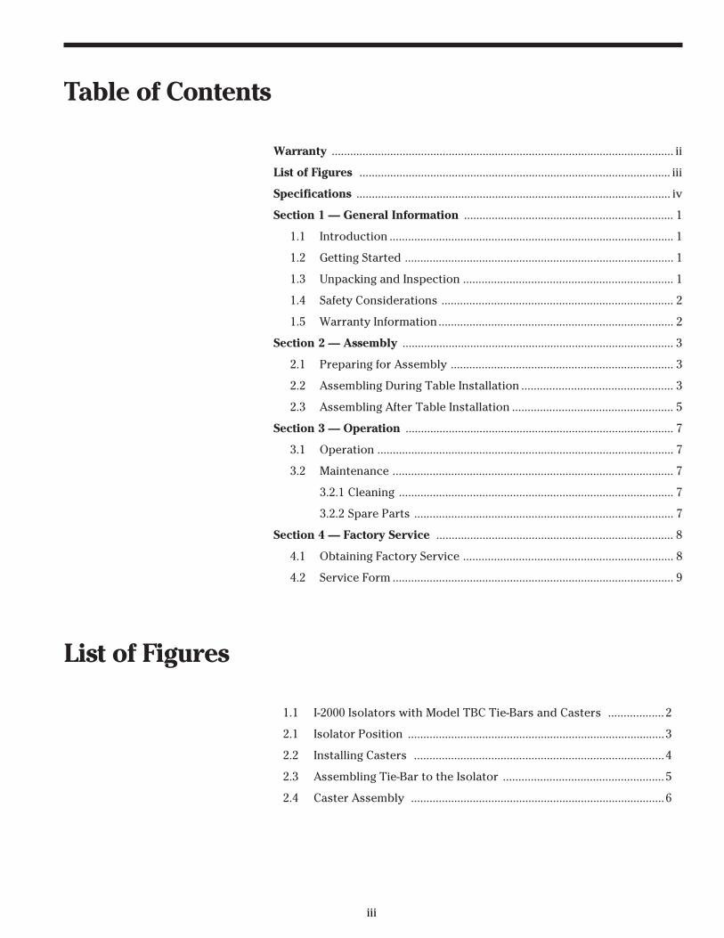
Table of Contents
Warranty ............................................................................................................... ii
List of Figures ..................................................................................................... iii
Specifications ...................................................................................................... iv
Section 1 — General Information .................................................................... 1
1.1 Introduction ............................................................................................ 1
1.2 Getting Started ....................................................................................... 1
1.3 Unpacking and Inspection .................................................................... 1
1.4 Safety Considerations ........................................................................... 2
1.5 Warranty Information ............................................................................ 2
Section 2 — Assembly ........................................................................................ 3
2.1 Preparing for Assembly ........................................................................ 3
2.2 Assembling During Table Installation ................................................. 3
2.3 Assembling After Table Installation .................................................... 5
Section 3 — Operation ....................................................................................... 7
3.1 Operation ................................................................................................ 7
3.2 Maintenance ........................................................................................... 7
3.2.1 Cleaning ......................................................................................... 7
3.2.2 Spare Parts .................................................................................... 7
Section 4 — Factory Service ............................................................................. 8
4.1 Obtaining Factory Service .................................................................... 8
4.2 Service Form ........................................................................................... 9
List of Figures
1.1 I-2000 Isolators with Model TBC Tie-Bars and Casters .................. 2
2.1 Isolator Position ...................................................................................3
2.2 Installing Casters .................................................................................4
2.3 Assembling Tie-Bar to the Isolator .................................................... 5
2.4 Caster Assembly ..................................................................................6

iv
Specifications
Load Capacity TBC-xx Series SystemStandard Capacity2800 lbs. (1271 kg.)
TBC-xx-HD Series SystemHeavy Duty Capacity5600 lbs. (2542 kg.)
TB-xx Series System2000 lbs. (908 kg.) perI-2000 Isolator in the System
Standard Sizes* English Tables English Metric Tables Metric Price(ft.) Model (m) Model
Tie-Bars and Casters4 × 6 TBC-46 1.2 × 1.8 M-TBC-46 $6194 × 8 TBC-48 1.2 × 2.4 M-TBC-48 $6194 × 10 TBC-410 1.2 × 3.0 M-TBC-410 $6194 × 12 TBC-412 1.2 × 3.6 M-TBC-412 $6195 × 6 TBC-56 1.5 × 1.8 M-TBC-56 $6195 × 8 TBC-58 1.5 × 2.4 M-TBC-58 $6195 × 10 TBC-510 1.5 × 3.0 M-TBC-510 $6195 × 12 TBC-512 1.5 × 3.6 M-TBC-512 $619
Tie-Bars only
4 × 6 TB-46 1.2 × 1.8 M-TB-46 $2604 × 8 TB-48 1.2 × 2.4 M-TB-48 $2604 × 10 TB-410 1.2 × 3.0 M-TB-410 $2604 × 12 TB-412 1.2 × 3.6 M-TB-412 $2605 × 6 TB-56 1.5 × 1.8 M-TB-56 $2605 × 8 TB-58 1.5 × 2.4 M-TB-58 $2605 × 10 TB-510 1.5 × 3.0 M-TB-510 $2605 × 12 TB-512 1.5 × 3.6 M-TB-512 $260
* For other sizes, contact your local Newport Representative

1
Section 1General Information
1.1 Introduction
The Newport TB Tie-Bar and TBC Tie-Bar with caster systems provide addi-tional stability for table systems that use the Stabilizer series isolators. Inaddition, the model TBC (with casters), provides a secure and safe method ofmoving the table and isolators as a complete assembly, without the need forforklifts or other specialized equipment.
The Newport TBC system is designed to alleviate stress in the table andisolator system during relocation.
1.2 Getting Started
Please read this instruction manual thoroughly before assembling the Tie-BarSystems.
1.3 Unpacking and Inspection
The components of the Newport TB and TBC Tie-Bar Systems are packed in asingle box. Be sure the number of boxes you received is equal to the totalnumber listed on the label (for example, if a box is labeled 1 of 4, there shouldbe 4 boxes).
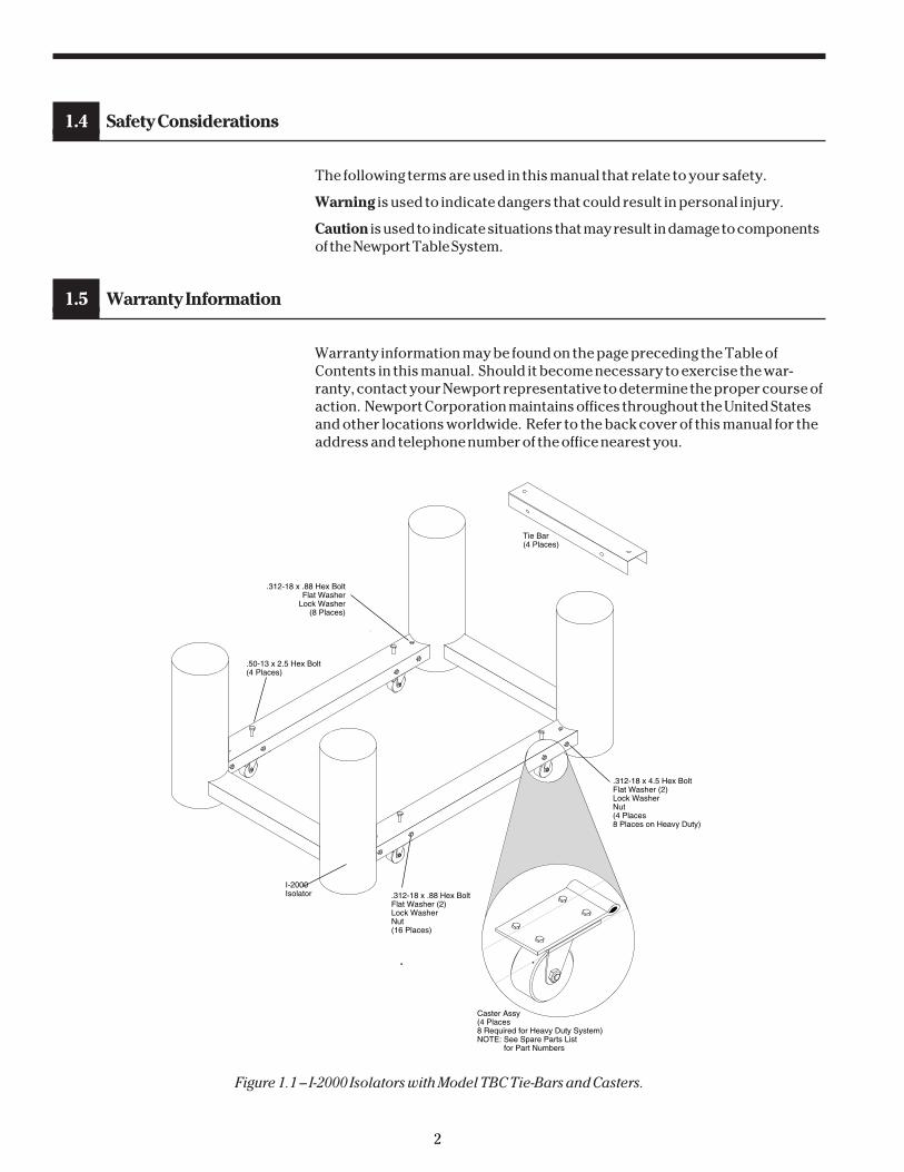
Use the diagram in Figure 1.1 to locate and identify each component as youremove it from the box. Carefully inspect all components for shipping dam-age. Report any shipping damage immediately to Newport and the shippingcompany.
The Newport TB Tie-Bar System should be ordered with the table system, andinstalled at the time of initial table installation. The TBC Casters may beordered as an accessory to be installed at a later date.
2
1.4 Safety Considerations
The following terms are used in this manual that relate to your safety.
Warning is used to indicate dangers that could result in personal injury.
Caution is used to indicate situations that may result in damage to componentsof the Newport Table System.
1.5 Warranty Information
Warranty information may be found on the page preceding the Table ofContents in this manual. Should it become necessary to exercise the war-ranty, contact your Newport representative to determine the proper course ofaction. Newport Corporation maintains offices throughout the United Statesand other locations worldwide. Refer to the back cover of this manual for theaddress and telephone number of the office nearest you.
.50-13 x 2.5 Hex Bolt(4 Places)
I-2000Isolator
.312-18 x 4.5 Hex BoltFlat Washer (2)Lock WasherNut(4 Places8 Places on Heavy Duty)
.312-18 x .88 Hex BoltFlat Washer (2)Lock WasherNut(16 Places)
Caster Assy(4 Places8 Required for Heavy Duty System)NOTE: See Spare Parts List for Part Numbers
.312-18 x .88 Hex BoltFlat Washer
Lock Washer(8 Places)
Tie Bar(4 Places)
Figure 1.1 – I-2000 Isolators with Model TBC Tie-Bars and Casters.

3
Section 2Assembly
2.1 Preparing For Assembly
The Newport Tie-Bar systems are fastened to the isolators of the NewportTable System. If you are installing the caster kit on a previously assembled TBsystem, skip to Section 2.3. If you are installing the Tie-Bars on a new tablesystem, proceed with Section 2.2.
2.2 Assembling During Table Installation
If you are installing a Newport Table system with Tie-Bars, use the followingprocedure to assemble the TB Tie-Bar System.
A. Unpack the Table System components as described in the NewportVibration Control System Instruction Manual. Ensure that the isolators havethe attachment bars required for the Tie-Bars.
B. Remove the Tie-Bars, casters (if ordered), and hardware from the packingcartons and place them on the floor near the table.NOTE: Casters may be pre-installed in the isolator attachment bars.
C. Refer to Figure 2.1 for correct placement of the isolators.
D Typ.
AB Typ.
6" (152 mm)4 PL
C
Leveling ValveBracket
Caster Location4 Places
Figure 2.1 Isolator Position
Table Distance DistanceLength A B
English Sizes: [in. (mm.)]6' 40 (987) 16 (406)8' 52 (1282) 22 (559)10' 66 (1682) 27 (686)12' 80 (1974) 32 (813)14' 94 (2420) 37 (940)16' 104 (2565) 42 (1087)18' 120 (2962) 47 (1194)20' 134 (3308) 53 (1346)
Metric Sizes: [mm.]1500 839.6 3301800 987.2 4062000 1120.0 4402100 1195.2 4523000 1628.4 6863600 1974.4 813
(Dimension D = Table Width - 12 in.)

4
D. Use the following procedure to install the casters. Casters must beinstalled on the attachment bars marked with an X in Figure 2.1.
CAUTION:Do not allow the isolator to tilt more than 60° from vertical. Damping
oil may spill from the isolator if it is tilted more than 60°.
1. Carefully tilt the first isolator so that the attachment bar is raisedapproximately 1.5 inches. (Figure 2.2).
2. Slide the caster, with its pivot hole toward the isolator, under theattachment bar. Ensure that the end of the caster mounting plate isabove the stop-bar as shown in Figure 2.2.
3. Return the isolator to its vertical position. Fasten the caster to theattachment bar with a .312-18 x 4.5-inch pivot bolt, lock washer, and nut.Use flat washers on both sides of the attachment bar (see Figure 2.3).
Align caster pivot hole with
holes in attachment bar.
Stop Bar
1.5"
Mounting Plate (above stop bar)
Figure 2.2 Installing Caster
4. Repeat steps 1 through 3 for the remaining isolators.
E. Place the four Tie-Bars over the attachment bars extending from theisolators. Ensure that the bolt holes on the top and side of the Tie-Barsare aligned with the holes in the attachment bars. (Figure 2.3).
F. Insert two .312-18 x .88-inch bolts with flat washers through the side holesin the Tie-Bar. Fasten the bolts with flat washers, lockwashers, and hexnuts inside the Tie-Bars. Do not tighten the bolts at this time.
G. Insert a .312-18 x .88-inch bolt with washers into the hole on top of theTie-Bar. Tighten the bolt hand-tight.
H. Ensure that the isolator spacing is as described in Figure 2.1.
I. When all four Tie-Bars have been installed, tighten all bolts securely.
J. If Casters were installed in step D, install a .50-13 x 2.5-inch Lifting Bolt inthe remaining hole at the top of each Tie-Bar. Thread the bolt into theassembly until it stops against the caster plate. Apply a small amount ofoil or grease to the bolt for smoother operation.

5
Pivot Bolt.312-18 x 4.5
.312-18 x .88" Bolt(3 Places)
Tie Bar
Figure 2.3 Assembling Tie-Bar to the Isolator
J. Refer to the Vibration Control System Instruction Manual to continueassembling the Table.
CAUTIONThe isolators must be bolted to the table using the Safelok™ clamps pro-vided with the isolators prior to lifting & moving the table on the casters.
2.3 Assembling After Table Installation
The following procedure is for installing the TBC Tie-Bar Casters to an existingTable System. This procedure assumes that the Table System is assembled,with the Tie-Bars and table top in place. Casters are installed in the attach-ment bars marked with an X in Figure 2.1.
A. Turn off the air supply to the table and allow the table to settle beforeproceeding.
B. Place a fork-lift or similar equipment under one of the longer Tie-Bars sothat the forks are no more than 12" (30 cm) from the isolators. Carefullyraise the table, isolators, and tie bar assembly approximately three inches.
WARNING:The assembled table system may weigh in excess of 1000 pounds (454 kg).Be sure the table is secured to the isolators using the Safelok™ clamps
provided with the isolators prior to lifting. Personal injury could result ifthe table slips off of the forklift. Place blocks under the raised isolators
before working under the Tie-Bars

6
C. Refer to Figure 2.4. Slide one caster under each end of the Tie-Bar so thatthe caster pivot hole is toward the isolator and the end of the castermounting plate is above the stop bar.
D. Fasten the casters to the attachment bars with the .312-18 x 4.5-inch pivotbolts and hex nuts. Be sure to install the flat washers on each side of theassembly.
E. Tighten the bolts to secure the casters and lower the table assembly untilthe isolators are resting on the floor.
F. Insert the .50-13 x 2.5-inch bolt through the top of the Tie-Bar at each end.Thread the bolts into the Tie-Bar until they stop on the caster plate.Apply a small amount of oil or grease to the bolt for smoother operation.
G. Repeat steps B through F for the Tie-Bar on the opposite side of the table.
.312-18x4.5 Pivot Bolt
.5-13x2.5 Bolt
Stop Bar Approx. 3"
Figure 2.4 Caster Assembly
H. Level and float the table as described in the Vibration Control SystemInstruction Manual.
CAUTIONThe isolators must be bolted to the table using the Safelok™ clamps pro-vided with the isolators prior to lifting & moving the table on the casters.

7
Section 3Operation
3.1 Operation
The Newport TBC Caster and Tie-Bar System provides a safe and stablemethod for moving an assembled Table System without the need for disas-sembling the table. To move the table after assembly:
A. Turn off the air supply and allow the table top to settle.
B. Ensure that the isolators are bolted to the table using the Safelok™ clamps.
C. Use a wrench to turn the four caster Lift Bolts clockwise (CW) into theTie-Bars, raising the isolators off the floor.
D. Carefully roll the table to its new location.
WARNING:There are no brakes on the casters. To prevent injury or damage do not
roll the table up or down ramps.
E. After relocating the table, turn the caster Lift Bolts counter-clockwise(CCW) until the isolators are resting on the floor.
F. Connect the air supply and refloat the table.
3.2 Maintenance
Newport TB and TBC systems require little maintenance. No periodic mainte-nance is required.
3.2.1 Cleaning
Newport Tie-Bars are made of painted carbon steel. They may be cleaned byapplying non-abrasive liquid household cleaner to a rag and wiping thesurface dry. Avoid abrasive cleaners as they will scratch the surface.
3.2.2 Spare Parts
Part Name Part No.Caster Assy 17847Kit, Caster Mounting 17853Kit, Tie Bar Mounting Hardware 17855Instruction Manual 19602Tie Bar 17574Consult Newport for proper length.
8
Section 4Factory Service
4.1 Obtaining Factory Service
To obtain information concerning factory service, contact Newport Corpora-tion or your Newport representative. Please have the following informationavailable.
1. Model number.
2. Purchase order number.
3. Complete description of the problem.
If components are to be returned to Newport Corporation, you will be given aReturn Authorization Number, which you should reference in your shippingdocuments.
Please fill out the service form located on the next page, and have the informa-tion ready when contacting Newport Corporation. Include the completedservice form with any parts or components that are returned.
Comments or Suggestions
This manual was prepared with the help of several of Newport’s customers.We gratefully acknowledge their assistance.
We would appreciate any comments or suggestions you may have to improvethis manual. Please call us at (714) 863-3144.

9
Name _____________________________________________________________________________________ RETURN AUTHORIZATION # ____________________________
Company _______________________________________________________________________________ (Please obtain prior to return of item)
Address _________________________________________________________________________________
Country _________________________________________________________________________________ Date _______________________________________________________________
P.O. Number __________________________________________________________________________ Phone Number ________________________________________________
Item(s) Being Returned:
Model # ________________________________________________________ Serial # __________________________________________________________________________________________
Description: _________________________________________________________________________________________________________________________________________________________
Reason for return of goods (please list any specific problems) ______________________________________________________________________________
____________________________________________________________________________________________________________________________________________________________________________
Please Describe the Problem:
____________________________________________________________________________________________________________________________________________________________________________
____________________________________________________________________________________________________________________________________________________________________________
____________________________________________________________________________________________________________________________________________________________________________
____________________________________________________________________________________________________________________________________________________________________________
_______________________________________________________________________________________________________________ (Attach additional sheets as necessary).
Where is the Equipment Installed?
(factory, controlled laboratory, out-of-doors, etc.) _______________________________________________________________________________________________
Maximum Air Pressure Available? ______________________________________ Regulated? _____________________________________
Any additional information. (If special modifications have been made by the user, please describe below).
___________________________________________________________________________________________________________________________________________________________________________
___________________________________________________________________________________________________________________________________________________________________________
___________________________________________________________________________________________________________________________________________________________________________
___________________________________________________________________________________________________________________________________________________________________________
Newport CorporationU.S.A. Office: 949/863-3144FAX: 949/253-1800
Service Form

10

Visit Newport Online at: www.newport.com
Newport Corporation, Irvine, California, hasbeen certified compliant with ISO 9001 bythe British Standards Institution.
P/N 19602-01 rev AIN-04923 (08-00)
Printed in the USA
Newport CorporationWorldwide Headquarters
1791 Deere AvenueIrvine, CA 92606
(In U.S.): 800-222-6440Tel: 949-863-3144Fax: 949-253-1680
Internet: [email protected]