*TB 9-6625-1176-35 - Top Dog Test · PDF fileprescribed by TB 750-25. b. Adjustments to be...
29
__________ *This bulletin supersedes TB 9-6625-1176-35, 21 December 1984, including all changes. *TB 9-6625-1176-35 SUPERSEDED COPY DATED 21 DECEMBER 1984 DEPARTMENT OF THE ARMY TECHNICAL BULLETIN CALIBRATION PROCEDURE FOR PULSE GENERATOR HEWLETT-PACKARD MODEL 214B Headquarters, Department of the Army, Washington, DC 6 May 1987 Approved for public release; distribution is unlimited. REPORTING OF ERRORS You can help improve this publication by calling attention to errors and by recommending improvements and stating your reasons for the recommendations. Your letter or DA Form 2028, Recommended Changes to Publications, should be mailed directly to Commander, U.S. Army Aviation and Missile Command, ATTN: AMSAM-TMD-EP, Redstone Arsenal, AL 35898-5400. You may also contact this office electronically. E-mail address is tmde- [email protected]. FAX to DSN 788-2313 (commercial 205-842-2313). A reply will be furnished directly to you. Paragraph Page SECTION I. IDENTIFICATION AND DESCRIPTION Test instrument identification ................. 1 2 Forms, records, and reports ..................... 2 2 Calibration description .............................. 3 2 II. EQUIPMENT REQUIREMENTS Equipment required ................................. 4 3 Accessories required ................................. 5 3 III. CALIBRATION PROCESS Preliminary instructions .......................... 6 4 Equipment Setup ...................................... 7 6 Pulse repetition rate ........................................... 8 6 Pulse position...................................................... 9 10 Pulse width and duty cycle ................................. 10 14 Pulse amplitude and characteristics .................. 11 19 Trigger output and double pulse ........................ 12 25 External trigger level and sensitivity ................ 13 26 Power supply ...................................................... 14 27 Final procedure .................................................. 15 28
Transcript of *TB 9-6625-1176-35 - Top Dog Test · PDF fileprescribed by TB 750-25. b. Adjustments to be...
__________ *This bulletin supersedes TB 9-6625-1176-35, 21 December 1984, including all changes.
*TB 9-6625-1176-35SUPERSEDED COPY DATED 21 DECEMBER 1984
DEPARTMENT OF THE ARMY TECHNICAL BULLETIN
CALIBRATION PROCEDURE FORPULSE GENERATOR
HEWLETT-PACKARD MODEL 214BHeadquarters, Department of the Army, Washington, DC
6 May 1987Approved for public release; distribution is unlimited.
REPORTING OF ERRORSYou can help improve this publication by calling attention to errors and byrecommending improvements and stating your reasons for therecommendations. Your letter or DA Form 2028, Recommended Changes toPublications, should be mailed directly to Commander, U.S. Army Aviation andMissile Command, ATTN: AMSAM-TMD-EP, Redstone Arsenal, AL 35898-5400.You may also contact this office electronically. E-mail address is [email protected]. FAX to DSN 788-2313 (commercial 205-842-2313). Areply will be furnished directly to you.
Paragraph PageSECTION I. IDENTIFICATION AND DESCRIPTION
Test instrument identification ................. 1 2Forms, records, and reports ..................... 2 2Calibration description .............................. 3 2
II. EQUIPMENT REQUIREMENTSEquipment required ................................. 4 3Accessories required ................................. 5 3
III. CALIBRATION PROCESSPreliminary instructions .......................... 6 4Equipment Setup ...................................... 7 6Pulse repetition rate ........................................... 8 6Pulse position...................................................... 9 10Pulse width and duty cycle................................. 10 14Pulse amplitude and characteristics .................. 11 19Trigger output and double pulse ........................ 12 25External trigger level and sensitivity ................ 13 26Power supply ...................................................... 14 27Final procedure .................................................. 15 28
TB 9-6625-1176-35
2
SECTION IIDENTIFICATION AND DESCRIPTION
1. Test Instrument Identification. This bulletin provides instructions for thecalibration of Pulse Generator, Hewlett-Packard, Model 214B. The manufacturer's manualwas used as the prime data sources in compiling these instructions. The equipment beingcalibrated will be referred to as the TI (test instrument) throughout this bulletin.
a. Model Variations. None.
b. Time and Technique. The time required for this calibration is approximately 4hours, using the dc and low frequency technique.
2. Forms, Records, and Reports
a. Forms, records, and reports required for calibration personnel at all levels areprescribed by TB 750-25.
b. Adjustments to be reported are designated (R) at the end of the sentence in whichthey appear. When adjustments are in tables, the (R) follows the designated adjustment.Report only those adjustments made and designated with (R).
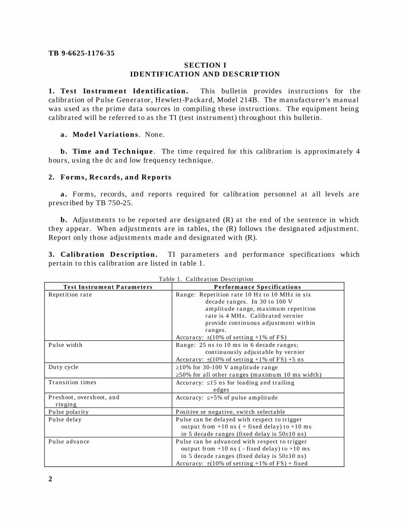
3. Calibration Description. TI parameters and performance specifications whichpertain to this calibration are listed in table 1.
Table 1. Calibration DescriptionTest Instrument Parameters Performance Specifications
Repetition rate Range: Repetition rate 10 Hz to 10 MHz in sixdecade ranges. In 30 to 100 Vamplitude range, maximum repetitionrate is 4 MHz. Calibrated vernierprovide continuous adjustment withinranges.
Accuracy: ±(10% of setting +1% of FS)Pulse width Range: 25 ns to 10 ms in 6 decade ranges;
continuously adjustable by vernierAccuracy: ±(10% of setting +1% of FS) +5 ns
Duty cycle ≥10% for 30-100 V amplitude range≥50% for all other ranges (maximum 10 ms width)
Transition times Accuracy: ≤15 ns for leading and trailingedges
Preshoot, overshoot, and ringing
Accuracy: ≤+5% of pulse amplitude
Pulse polarity Positive or negative, switch selectablePulse delay Pulse can be delayed with respect to trigger
output from +10 ns ( + fixed delay) to +10 ms in 5 decade ranges (fixed delay is 50 ±10 ns)
Pulse advance Pulse can be advanced with respect to trigger output from +10 ns ( - fixed delay) to +10 ms in 5 decade ranges (fixed delay is 50 ±10 ns)Accuracy: ±(10% of setting +1% of FS) + fixed
TB 9-6625-1176-35
3
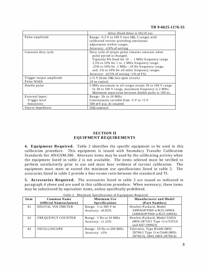
delay (fixed delay is 50 ±10 ns)Pulse amplitude Range: 0.3 V to 100 V into 50Ω, 5 ranges with
calibrated vernier providing continuousadjustment within ranges.Accuracy: ±10% of setting
Constant duty cycle Duty cycle of output pulse remains constant when pulse period is changed. Typically 8% fixed for 10 - 1 MHz frequency range 2.5% to 10% for 1 to .1 MHz frequency range, .25% to 10% for .1 MHz - 10 Hz frequency range, and .1% to 10% for all other frequency rangesAccuracy: ±(15% of setting +1% of FS)
Trigger output amplitudePulse Width
≥+5 V (from 50Ω into open circuit)10 ns typical
Double pulse 5 MHz maximum in all ranges except 30 to 100 V range.In 30 to 100 V range, maximum frequency is 2 MHz.Minimum separation between double pulse is 100 ns.
External input: Trigger level Sensitivity
Range: Dc to 10 MHzContinuously variable from -5 V to +5 V500 mV p-p, dc coupled
Source impedance 50Ω nominal
SECTION IIEQUIPMENT REQUIREMENTS
4. Equipment Required. Table 2 identifies the specific equipment to be used in thiscalibration procedure. This equipment is issued with Secondary Transfer CalibrationStandards Set AN/GSM-286. Alternate items may be used by the calibrating activity whenthe equipment listed in table 2 is not available. The items selected must be verified toperform satisfactorily prior to use and must bear evidence of current calibration. Theequipment must meet or exceed the minimum use specifications listed in table 2. Theaccuracies listed in table 2 provide a four-to-one ratio between the standard and TI.
5. Accessories Required. The accessories listed in table 3 are issued as indicated inparagraph 4 above and are used in this calibration procedure. When necessary, these itemsmay be substituted by equivalent items, unless specifically prohibited.
Table 2. Minimum Specifications of Equipment RequiredItem Common Name
(Official Nomenclature)Minimum UseSpecifications
Manufacturer and Model(Part Number)
A1 DIGITAL VOLTMETER Range: 5 to 300 V dcAccuracy: ±0.02%
Hewlett-Packard, Model3490AOPT060 w/K25-3490A(3490AOPT060 w/K25-3490A)
A2 FREQUENCY COUNTER Range: 1 Hz to 10 MHzAccuracy: ±1.25%
Hewlett-Packard, Model 5345A(MIS-28754/1 Type 1) w/5355Aand K87-59992A
A3 OSCILLOSCOPE Range: 10 Hz to 200 MHzAccuracy: ±5%
Tektronix, Type R5440 (MIS-28706/1 Type 1) w/5A48 (MIS-28706/3), 5B42 (MIS-28706/4)

TB 9-6625-1176-35
4
and 5S14 (MIS-28706/5)A4 SIGNAL GENERATOR Range: 300 mV to 11 V p-p
Accuracy: N/AWavetek, Model 145 (7915944)
A5 TERMINATION LOAD(DUMMY LOAD)
Range: N/A Narda, Model 374BNM (374BNM)
Table 3. Accessories RequiredItem Common Name
(Official Nomenclature)Description
(Part Number)B1 ADAPTER BNC T-type, 2 jacks, 1 plug (MS-35173-274C)B2 ADAPTER BNC plug to N jack (10519458)B3 ADAPTER BNC plug to double banana jacks (7909401)
(UG1441/U)B4 ADAPTER
(CALIBRATIONFIXTURE)
Flexible T-type, 2 jacks, 1 plug (067-05250-01 or 067-0525-02)
B5 ATTENUATOR1 X10, Tektronix, Type 011-0059-02B6 CABLE2 30-in., RG-58/U; BNC plug terminations
(7907467)B7 LEAD1 32-in., single banana plug to test hook (red)
(7915941-1)B8 PROBE
(TEST LEAD)36-in., BNC plug to X10 probe, Tektronix. Type P6106 (010-6106-01)
B9 TERMINATION(DUMMY LOAD)
50Ω feed-through, BNC plug to BNC jack (11048B or 11048C)
1Two required.2Three required.
SECTION IIICALIBRATION PROCESS
6. Preliminary Instructions
a. The instructions outlined in paragraphs 6 and 7 are preparatory to the calibrationprocess. Personnel should become familiar with the entire bulletin before beginning thecalibration.
b. Items of equipment used in this procedure are referenced within the text by commonname and item identification number as listed in tables 2 and 3. For the identification ofequipment referenced by item numbers prefixed with A, see table 2, and for prefix B, seetable 3.
c. Unless otherwise specified, verify the result of each test and, whenever the testrequirement is not met, take corrective action before continuing with the calibration.Adjustments required to calibrate the TI are included in this procedure. Additionalmaintenance information is contained in the manufacturer's manual for this TI.
d. When indications specified in paragraphs 8 through 13 are not withi n tolerance,perform the power supply check prior to making adjustments. After adjustments are made,

TB 9-6625-1176-35
5
repeat paragraphs 8 through 13. Do not perform power supply check if all otherparameters are within tolerance.
e. Unless otherwise specified, all controls and control settings refer to the TI.

TB 9-6625-1176-35
6
7. Equipment Setup
WARNINGHIGH VOLTAGE is used or exposed during the performance ofthis calibration. DEATH ON CONTACT may result ifpersonnel fail to observe safety precautions.
a. Remove TI protective covers as required for adjustment.
b. Connect TI to a 115-V 60 Hz ac source.
c. Energize equipment and allow sufficient time for equipment to warm up andstabilize.
8. Pulse Repetition Rate
a. Performance Check
(1) Position controls as listed in (a) through (n) below:
(a) MODE NORM pushbutton pressed.
(b) PERIOD .1µµ-1µµ pushbutton pressed.
(c) PERIOD VERNIER dial to 10.
(d) PULSE POSITION l0n-.1µµ pushbutton pressed.
(e) PULSE POSITION VERNIER dial to 1.
(f) DUTY CYCLE % pushbutton released (out).
(g) WIDTH .1µµ-1µµ pushbutton pressed.
(h) WIDTH VERNIER dial fully ccw.
(i) AMPLITUDE 3-10 pushbutton pressed.
(j) AMPLITUDE VERNIER dial to 3.
(k) INT LOAD pushbutton released (out).
(l) SLOPE switch to POS.
(m) DELAY/ADVANCE/DOUBLE PULSE switch to DELAY.

TB 9-6625-1176-35
7
(n) POLARITY switch to POS.
(2) Connect TRIG OUTPUT to frequency counter (A2) A input, using cable andtermination (B6 and B9).
(3) Measure REPETITION RATE, using standard measurement technique. Iffrequency counter does not indicate between 890 and 1110 ns, perform b below.
(4) Repeat technique of (3) above for settings listed in table 4. If indications are notwithin specified tolerance, perform b below.
Table 4. Repetition RateTest Instrument Frequency Counter Indications
PERIODPushbuttons
PERIOD VERNIERDial Settings
Min Max
1µ - 10µ 10 8.900 µs 11.100 µs10µ - .1 m 10 89 µs 111 µs.1m - 1m 10 890 µs 1.100 ms1m - 10m 10 8.900 ms 11.1 ms10m - .1 10 89 ms 111 ms10m - .1 1 8.000 ms 12.000 ms1m - 10m 1 800 µs 1.200 ms.1m - 1m 1 80 µs 120 µs10µ - .1m 1 8.000 µs 12.000 µs1µ - 10µ 1 800 ns 1.200 µs.1µ - 1µ 1 80 ns 120 ns.1µ - 1µ 2 170 ns 230 ns.1µ - 1µ 3 260 ns 340 ns.1µ - 1µ 4 350 ns 450 ns.1µ - 1µ 5 440 ns 560 ns.1µ - 1µ 6 530 ns 670 ns.1µ - 1µ 7 620 ns 780 ns.1µ - 1µ 8 710 ns 890 ns.1µ - 1µ 9 800 ns 1.000 µs
b. Adjustments
(1) Position controls as listed in (a) through (g) below:
(a) PERIOD .1µµ-1µµ pushbutton pressed.
(b) PERIOD VERNIER dial fully ccw.
(c) PULSE POSITION 10n-.1µµ pushbutton pressed.
(d) PULSE POSITION VERNIER dial to 1.
(e) DUTY CYCLE % pushbutton pressed.
TB 9-6625-1176-35
8
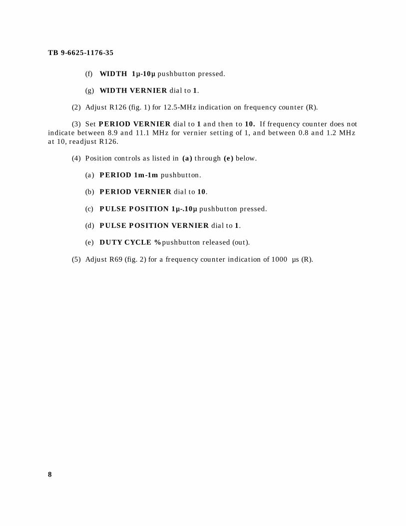
(f) WIDTH 1µµ-10µµ pushbutton pressed.
(g) WIDTH VERNIER dial to 1.
(2) Adjust R126 (fig. 1) for 12.5-MHz indication on frequency counter (R).
(3) Set PERIOD VERNIER dial to 1 and then to 10. If frequency counter does notindicate between 8.9 and 11.1 MHz for vernier setting of 1, and between 0.8 and 1.2 MHzat 10, readjust R126.
(4) Position controls as listed in (a) through (e) below.
(a) PERIOD 1m-1m pushbutton.
(b) PERIOD VERNIER dial to 10.
(c) PULSE POSITION 1µµ-.10µµ pushbutton pressed.
(d) PULSE POSITION VERNIER dial to 1.
(e) DUTY CYCLE % pushbutton released (out).
(5) Adjust R69 (fig. 2) for a frequency counter indication of 1000 µs (R).

TB 9-6625-1176-35
9

TB 9-6625-1176-35
10
Figure 1. A2 (timing board) adjustment locations (top forward view).
Figure 2. A1 (amplifier board) - adjustment locations.
(6) Set PERIOD VERNIER dial to 1.
(7) Adjust R46 (fig. 1) for a frequency counter indication of 100 µs (R).
(8) Set PERIOD VERNIER dial to 10 and repeat (5) through (7) above for best in-tolerance condition.
9. Pulse Position
a. Performance Check
(1) Position controls as listed in (a) through (d) below:
(a) PERIOD VERNIER dial to 10.
(b) DUTY CYCLE % pushbutton pressed.
(c) AMPLITUDE 1-3 pushbutton pressed.
(d) PULSE POSITION VERNIER dial to 10.

TB 9-6625-1176-35
11
(2) Connect TRIG OUTPUT to frequency counter (A2) A input, using cable andtermination (B6 and B9). Connect OUTPUT to frequency counter B input, using cable(B6).

TB 9-6625-1176-35
12
NOTEIf an out-of-tolerance reading is obtained in (3) through (10)below, perform b below.
(3) Measure time between TRIG OUTPUT and OUTPUT pulses, using standardmeasurement technique. Frequency counter will indicate between 129 and 171 ns.
(4) Set PULSE POSITION VERNIER dial to 1. Frequency counter will indicatebetween 48 and 72 ns.
(5) Disconnect OUTPUT from frequency counter and setDELAY/ADVANCE/DOUBLE PULSE switch to ADVANCE. Connect TRIG OUTPUTto oscilloscope (A3) CH 1 input, using cable (B6). Connect OUTPUT to oscilloscope CH 2input, using cable (B6).
(6) Measure time between TRIG OUTPUT and OUTPUT pulses, using standardmeasurement technique. The results will be between 28 and 52 ns.
(7) Set PULSE POSITION VERNIER dial to 10 and connect TI OUTPUT tooscilloscope (A3) CH 2 and EXT trigger inputs.
(7.1) Set oscilloscope (A3) trigger source INT/EXT switch to EXT and measurethe time between and OUTPUT and TRIG OUTPUT pulses. Results will be between 29and 71 ns.
(8) Disconnect cables from oscilloscope in puts and repeat (2) above.
(9) Position controls as listed in (a) through (d) below:
(a) PERIOD l0m-.1 pushbutton pressed.
(b) PERIOD VERNIER dial to 1.
(c) PULSE POSITION .lµµ-lµµ pushbutton pressed.
(d) DELAY/ADVANCE/DOUBLE PULSE switch to DELAY.
(10) Repeat technique of (3) above for settings listed in table 5. Indications will bewithin specified limits.
b. Adjustments
(1) Position controls as listed in (a) through (i) below:
(a) PERIOD 1m-10m pushbutton pressed.
(b) PERIOD VERNIER dial to 10.
TB 9-6625-1176-35
13
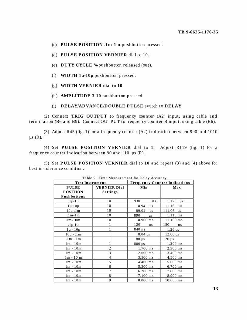
(c) PULSE POSITION .1m-1m pushbutton pressed.
(d) PULSE POSITION VERNIER dial to 10.
(e) DUTY CYCLE % pushbutton released (out).
(f) WIDTH 1µµ-10µµ pushbutton pressed.
(g) WIDTH VERNIER dial to 10.
(h) AMPLITUDE 3-10 pushbutton pressed.
(i) DELAY/ADVANCE/DOUBLE PULSE switch to DELAY.
(2) Connect TRIG OUTPUT to frequency counter (A2) input, using cable andtermination (B6 and B9). Connect OUTPUT to frequency counter B input, using cable (B6).
(3) Adjust R45 (fig. 1) for a frequency counter (A2) i ndication between 990 and 1010µs (R).
(4) Set PULSE POSITION VERNIER dial to 1. Adjust R119 (fig. 1) for afrequency counter indication between 90 and 110 µs (R).
(5) Set PULSE POSITION VERNIER dial to 10 and repeat (3) and (4) above forbest in-tolerance condition.
Table 5. Time Measurement for Delay AccuracyTest Instrument Frequency Counter Indications
PULSEPOSITION
Pushbuttons
VERNIER DialSettings
Min Max
.1µ-1µ 10 930 ns 1.170 µs1µ-10µ 10 8.94 µs 11.16 µs
10µ-.1m 10 89.04 µs 111.06 µs.1m-1m 10 890 µs 1.110 ms1m-10m 10 8.900 ms 11.100 ms.1µ-1µ 1 120 ns 180 ns
1µ - 10µ 1 840 ns 1.26 µs10µ - .1m 1 8.04 µs 12.06 µs.1m - 1m 1 80 µs 120 µs1m - 10m 1 800 µs 1.200 ms1m - 10m 2 1.700 ms 2.300 ms1m - 10m 3 2.600 ms 3.400 ms1m - 10 m 4 3.500 ms 4.500 ms1m - 10m 5 4.400 ms 5.600 ms1m - 10m 6 5.300 ms 6.700 ms1m - 10m 7 6.200 ms 7.800 ms1m - 10m 8 7.100 ms 8.900 ms1m - 10m 9 8.000 ms 10.000 ms

TB 9-6625-1176-35
14
10. Pulse Width and Duty Cycle
a. Performance Check
(1) Connect equipment as shown in. figure 3.
(2) Position controls as listed in (a) through (j) below.
(a) PERIOD 1µµ-10µµ pushbutton pressed.
(b) PERIOD VERNIER dial to 10.
(c) PULSE POSITION 10n-.1µµ pushbutton pressed.
(d) PULSE POSITION VERNIER dial to 10.
(e) DUTY CYCLE % pushbutton released (out).
(f) WIDTH 25n-.1µµ pushbutton pressed.
(g) WIDTH VERNIER dial to 2.5.
(h) AMPLITUDE 10-30 pushbutton pressed.
(i) AMPLITUDE VERNIER dial to 3 (30V).
(j) INT LOAD pushbutton pressed.
NOTEIf an out-of-tolerance condition is noted in (3) through (27)below, perform b below.
(3) Adjust controls of oscilloscope (A3) to display 1 pulse of TI output. Pulse widthwill be between 21.5 and 33.5 ns.
(4) Set WIDTH VERNIER dial to 10. Pulse width will be between 89 and 116 ns.
(5) Press WIDTH .1µµ-1µµ pushbutton. Pulse width will be between 0.890 and 1.115µs.
(6) Set WIDTH VERNIER dial to 1. Pulse width will be between 80 and 125 ns.
(7) Press PERIOD .1µµ-1µµ pushbutton and set PERIOD VERNIER dial to 3.Adjust oscilloscope controls to display 1 period of TI output.

TB 9-6625-1176-35
15
(8) Slowly increase WIDTH VERNIER dial until oscilloscope display disappears.Oscilloscope display will disappear at a duty cycle of 50 percent or greater (pulse width of150 ns or greater).
(9) Position controls as listed in (a) through (c) below:
(a) WIDTH 25n-.1µµ pushbutton pressed.
(b) AMPLITUDE 30-100 pushbutton pressed.
(c) AMPLITUDE VERNIER dial to 10 (50V).
(10) Repeat technique of (8) above. Oscilloscope display w ill disappear at a dutycycle of 10 percent or greater (pulse width of 30 ns or greater).
(11) Position controls as listed in (a) through (e) below:
(a) PERIOD 10m-. 1 pushbutton pressed.
(b) AMPLITUDE 1-3 pushbutton pressed.
(c) AMPLITUDE VERNIER dial to 3.
(d) WIDTH 1µµ-10µµ pushbutton pressed.
(e) WIDTH VERNIER dial to 1.
(12) Disconnect TI from oscilloscope and connect OUTPUT to frequency counter (A2)A and B inputs, using cable and adapter (B6 and B4).
(13) Measure pulse width, using standard mea surement technique. Frequencycounter will indicate between 0.8 and 1.205 µs.
(14) Repeat technique of (13) above, using settings listed in table 6. Indications willbe within specified limits.
(15) Disconnect OUTPUT from frequency counter and connect to oscilloscope CH 1input, using cable and attenuator (B6 and B5).
(16) Connect TRIG OUTPUT to frequency counter A input and oscilloscope externaltrigger input, using cables, adapter, and termination (B6, B1, and B9).
(17) Position controls as listed in (a) through (e) below:
(a) PERIOD .1µµ-1µµ pushbutton pressed.

TB 9-6625-1176-35
16
(b) PERIOD VERNIER dial to 10.
(c) PULSE POSITION VERNIER dial to 1.
(d) DUTY CYCLE % pushbutton pressed.
(e) INT LOAD pushbutton released (out).
(18) Set PERIOD VERNIER for exactly 1000 ns frequency counter indication.Oscilloscope will display a pulse width of approximately 80 ns (8 percent duty cycle).
(19) Press PERIOD 1µµ-10µµ pushbutton and set PERIOD VERNIER for a 10,000 nsfrequency counter indication (2.5-10 percent duty cycle LED is illuminated).
Figure 3. Equipment setup - pulse width and duty cycle.
TB 9-6625-1176-35
17
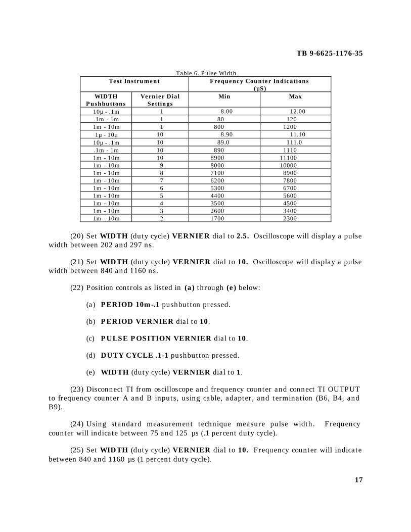
Table 6. Pulse WidthTest Instrument Frequency Counter Indications
(µµS)WIDTH
PushbuttonsVernier Dial
SettingsMin Max
10µ - .1m 1 8.00 12.00.1m - 1m 1 80 1201m - 10m 1 800 12001µ - 10µ 10 8.90 11.10
10µ - .1m 10 89.0 111.0.1m - 1m 10 890 11101m - 10m 10 8900 111001m - 10m 9 8000 100001m - 10m 8 7100 89001m - 10m 7 6200 78001m - 10m 6 5300 67001m - 10m 5 4400 56001m - 10m 4 3500 45001m - 10m 3 2600 34001m - 10m 2 1700 2300
(20) Set WIDTH (duty cycle) VERNIER dial to 2.5. Oscilloscope will display a pulsewidth between 202 and 297 ns.
(21) Set WIDTH (duty cycle) VERNIER dial to 10. Oscilloscope will display a pulsewidth between 840 and 1160 ns.
(22) Position controls as listed in (a) through (e) below:
(a) PERIOD 10m-.1 pushbutton pressed.
(b) PERIOD VERNIER dial to 10.
(c) PULSE POSITION VERNIER dial to 10.
(d) DUTY CYCLE .1-1 pushbutton pressed.
(e) WIDTH (duty cycle) VERNIER dial to 1.
(23) Disconnect TI from oscilloscope and frequency counter and connect TI OUTPUTto frequency counter A and B inputs, using cable, adapter, and termination (B6, B4, andB9).
(24) Using standard measurement technique measure pulse width. Frequencycounter will indicate between 75 and 125 µs (.1 percent duty cycle).
(25) Set WIDTH (duty cycle) VERNIER dial to 10. Frequency counter will indicatebetween 840 and 1160 µs (1 percent duty cycle).

TB 9-6625-1176-35
18
(26) Press DUTY CYCLE 1-10 pushbutton and set WIDTH (duty cycle) VERNIERdial as listed in table 7. Frequency counter will indicate within specified limits.
(27) Set PERIOD VERNIER dial to 1. Frequency counter will indicate between 75and 125 µs.
b. Adjustments
(1) Position controls as listed in (a) through (g) below:
(a) PERIOD 1m-10m pushbutton pressed.
(b) PERIOD VERNIER dial to 10.
(c) PULSE POSITION .1µµ-1µµ pushbutton pressed.
(d) PULSE POSITION VERNIER dial to 1.
(e) DUTY CYCLE % pushbutton pressed.
(f) DUTY CYCLE 1-10 pushbutton pressed.
(g) WIDTH (duty cycle) VERNIER dial to 10.
(2) Connect OUTPUT to frequency counter (A2) A and B inputs, using cable andadapter (B6 and B4).
(3) Set frequency counter to measure period and set PERIOD VERNIER for a10,000 µs frequency counter indication.
(4) Set frequency counter to measure pulse width and adjust R51 (fig. 1) for a 1000µs frequency counter indication (10 percent duty cycle) (R).
(5) Repeat technique of b(3) above and set PERIOD VERNIER for a 1000-µsfrequency counter indication.
(6) Repeat technique of b(4) above and adjust R217 (fig. 1) for a 100 µs frequencycounter indication (1 percent duty cycle) (R).
NOTEDue to interaction between adjustments, repeat b(3) through(6) above if necessary.
(7) Release DUTY CYCLE % pushbutton.
TB 9-6625-1176-35
19
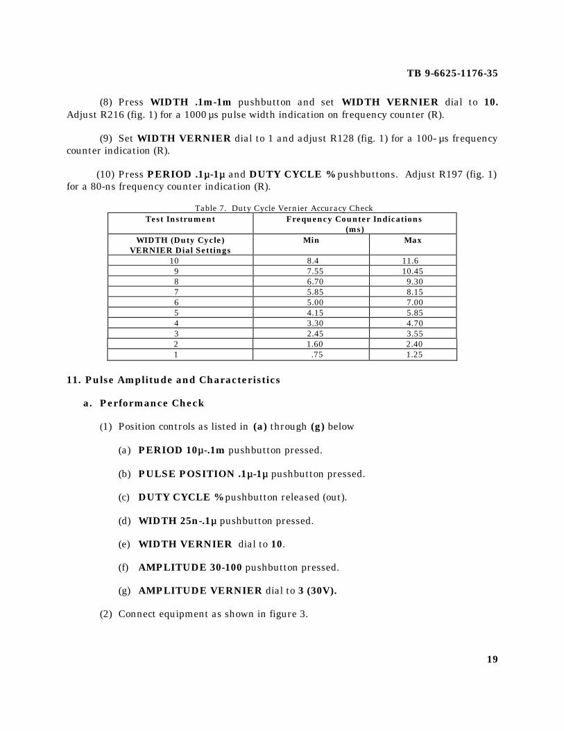
(8) Press WIDTH .1m-1m pushbutton and set WIDTH VERNIER dial to 10.Adjust R216 (fig. 1) for a 1000 µs pulse width indication on frequency counter (R).
(9) Set WIDTH VERNIER dial to 1 and adjust R128 (fig. 1) for a 100- µs frequencycounter indication (R).
(10) Press PERIOD .1µµ-1µµ and DUTY CYCLE % pushbuttons. Adjust R197 (fig. 1)for a 80-ns frequency counter indication (R).
Table 7. Duty Cycle Vernier Accuracy CheckTest Instrument Frequency Counter Indications
(ms)WIDTH (Duty Cycle)
VERNIER Dial SettingsMin Max
10 8.4 11.69 7.55 10.458 6.70 9.307 5.85 8.156 5.00 7.005 4.15 5.854 3.30 4.703 2.45 3.552 1.60 2.401 .75 1.25
11. Pulse Amplitude and Characteristics
a. Performance Check
(1) Position controls as listed in (a) through (g) below
(a) PERIOD 10µµ-.1m pushbutton pressed.
(b) PULSE POSITION .1µµ-1µµ pushbutton pressed.
(c) DUTY CYCLE % pushbutton released (out).
(d) WIDTH 25n-.1µµ pushbutton pressed.
(e) WIDTH VERNIER dial to 10.
(f) AMPLITUDE 30-100 pushbutton pressed.
(g) AMPLITUDE VERNIER dial to 3 (30V).
(2) Connect equipment as shown in figure 3.

TB 9-6625-1176-35
20
NOTEIf an out-of-tolerance condition is noted in (3) or (4) below,perform b(1) through (7) below.
(3) Oscilloscope will display a pulse with an amplitude between 27 and 33 V. PressINT LOAD pushbutton. Pulse amplitude will be between 13.5 and 16.5 V.
(4) Repeat technique of (3) above for settings listed in table 8. Oscilloscope willindicate within specified limits.
(5) Press AMPLITUDE 10-30 pushbutton and set AMPLITUDE VERNIER dialto 1 (10V).
(6) Using standard measurement technique, measure the rise time and decay timeof the OUTPUT pulse. If the rise time and decay time are not less than 15 ns, performb(8) through (21) below.
(7) Set POLARITY switch to NEG and repeat (6) above.
(8) Measure preshoot, overshoot, and ringing of positive and negative OUTPUTpulse. If measurement is not lest than 5 percent as shown in figure 4, perform b(8) through(21) below.
b. Adjustments
(1) Position controls as listed in (a) through (j) below:
Table 8. Pulse Amplitude Accuracy CheckTest Instrument Oscilloscope Indications
AMPLITUDERange
VernierDial
INT LOAD OFF(V)
INT LOAD ON(V)
Pushbuttons Settings Min Max30-100 10 90 110 45 5510-30 3 27 33 13.5 16.510-30 1 9 11 4.5 5.5.3-1 3 .27 .33 - - - - - -.3-1 10 .9 1.1 - - - - - -1-3 3 2.7 3.3 - - - - - -1-3 1 .9 1.1 - - - - - -3-10 3 2.7 3.3 - - - - - -3-10 4 3.6 4.4 - - - - - -3-10 5 4.5 5.5 - - - - - -3-10 6 5.4 6.6 - - - - - -3-10 7 6.3 7.7 - - - - - -3-10 8 7.2 8.8 - - - - - -3-10 9 8.1 9.9 - - - - - -3-10 10 9 11 - - - - - -

TB 9-6625-1176-35
21
Figure 4. Preshoot, overshoot, and ringing characteristics.
(a) PERIOD l0m-.1 pushbutton pressed.
(b) PERIOD VERNIER dial to 10.
(c) PULSE POSITION l0n-.1µµ pushbutton pressed.
(d) PULSE POSITION VERNIER dial to 1.
(e) DUTY CYCLE % pushbutton pressed.
(f) DUTY CYCLE 1-10 pushbutton pressed.
(g) WIDTH VERNIER dial to 5.
(h) AMPLITUDE 30-100 pushbutton pressed.
(i) AMPLITUDE VERNIER dial to 3 (30V).
(j) INT LOAD pushbutton released (out).
(2) Set R462 (fig. 2) fully cw and adjust R457 (fig. 2) for a 29-V pulse amplitudedisplay on oscilloscope (R).
(3) Set AMPLITUDE VERNIER dial to 10 and adjust R462 for a 105-V pulseamplitude display on oscilloscope (R).
(4) Repeat (2) and (3) above for best in tolerance condition.
(5) Press AMPLITUDE 10 - 30 pushbutton and set AMPLITUDE VERNIER dialto 1. Oscilloscope will display a pulse amplitude between 9 and 11 V.

TB 9-6625-1176-35
22
(6) Set AMPLITUDE VERNIER dial fully ccw. If oscilloscope does not display apulse amplitude of less than 10 V, readjust R457.
(7) Press AMPLITUDE 3 -10 pushbutton and set AMPLITUDE VERNIER dialfully cw. If oscilloscope does not display a pulse amplitude greater than 10 V, readjustR462.
(8) Position controls as listed in (a) through (h) below:
(a) PERIOD lµµ-10µµ pushbutton pressed.
(b) PERIOD VERNIER dial to 10.
(c) PULSE POSITION l0n-.1µµ pushbutton pressed.
(d) PULSE POSITION VERNIER dial to 1.
(e) WIDTH VERNIER dial to 2.5.
(f) AMPLITUDE 10-30 pushbutton pressed.
(f.1) DUTY CYCLE pushbutton pressed.
(f.2) WIDTH 25N-.lµµ pushbutton pressed.
(g) AMPLITUDE VERNIER dial to 3 (30V).
(h) POLARITY switch to POS.
(9) Adjust R480 (fig. 2) for a 25-ns pulse width indication on oscill oscope (R).
(10) Position controls as listed in (a) through (e) below:
(a) WIDTH .lµµ-lµµ pushbutton pressed.
(b) WIDTH VERNIER dial to 2.
(c) INT LOAD pushbutton pressed.
(d) AMPLITUDE 30 - 100 pushbutton pressed.
(e) AMPLITUDE VERNIER dial to 10 (50V).
(11) Adjust R436 and R408 (fig. 2) for fastest risetime display indication onoscilloscope (R).
(12) Adjust R419 (fig. 2) for minimum overshoot on oscilloscope display (R).

TB 9-6625-1176-35
23
(13) Observe oscilloscope risetime, overshoot, and ringing. If risetime is not less than15 ns, and overshoot and ringing less than 5 percent, readjust R419, R436, and R408 (fig.2).
(14) Press AMPLITUDE 10 - 30 pushbutton and set AMPLITUDE VERNIER dialto 3.
(15) Adjust C501 (fig. 5) for an overshoot equal to pulse ringing (R).
(16) Adjust R487 and R421 (fig. 2) for flat pulse top, and adjust C504 (fig. 5) foroptimum overshoot and ringing (R).
(17) Observe oscilloscope risetime, overshoot, and ringing. If risetime is not less than15 ns, and overshoot and ringing less than 5 percent, readjust C501, (fig. 5) C504, R421,and R487 (fig. 2) for optimum pulse.
(18) Release INT LOAD pushbutton and repeat technique of (17) above.
(19) Press AMPLITUDE 30-100 pushbutton and set AMPLITUDE VERNIER dialto 10 (100V). Repeat technique of (17) above.
(20) Press INT LOAD pushbutton and repeat technique of (17) above.
(21) Press AMPLITUDE .3-1 pushbutton and adjust C514 (fig. 1) for minimumringing (R).
Figure 5. A3 (load board) - adjustment locations.

TB 9-6625-1176-35
24

TB 9-6625-1176-35
25
12. Trigger Output and Double Pulse
a. Performance Check
(1) Position controls as listed in (a) through (g) below:
(a) PERIOD .1µµ-1µµ pushbutton pressed.
(b) PERIOD VERNIER dial to 2.
(c) PULSE POSITION 10n-.1µµ pushbutton pressed.
(d) PULSE POSITION VERNIER dial to 1.
(e) AMPLITUDE 3-10 pushbutton pressed.
(f) AMPLITUDE VERNIER dial to 3.
(g) INT LOAD pushbutton released (out).
(2) Connect TRIG OUTPUT to oscilloscope (A3) CH 1 input, using cable andtermination (B6 and B9). Oscilloscope will display a pulse amplitude greater than 2.5 Vand a pulse width of 10 ns.
(3) Connect equipment shown in figure 3.
(4) Position controls as listed in (a) through (h) below:
(a) PERIOD VERNIER dial to 5.
(b) PULSE POSITION .1µµ-1µµ pushbutton pressed.
(c) PULSE POSITION VERNIER dial to 2.
(d) WIDTH 25n-.1µµ pushbutton pressed.
(e) WIDTH VERNIER dial to 2.
(f) AMPLITUDE 30-100 pushbutton pressed.
(g) AMPLITUDE VERNIER dial to 5.
(h) DELAY/ADVANCE/DOUBLE PULSE switch to DOUBLE PULSE.
(5) Adjust PULSE POSITION VERNIER dial slowly ccw. Oscilloscope will stilldisplay both pulses when minimum separation of 100 ns is reached.

TB 9-6625-1176-35
26
(6) Set PERIOD VERNIER dial to 2 and press AMPLITUDE 3-10 pushbutton.Oscilloscope will display corresponding double pulse.
b. Adjustments. No adjustments can be made.
13. External Trigger Level and Sensitivity
a. Performance Check
(1) Position controls as listed in (a) through (f) below:
(a) MODE EXT TRIG pushbutton pressed.
(b) PULSE POSITION 10n-.1µµ pushbutton pressed.
(c) PULSE POSITION VERNIER dial to 1.
(d) WIDTH .1µµ-1µµ pushbutton pressed.
(e) WIDTH VERNIER dial to 10.
(f) DELAY/ADVANCE/DOUBLE PULSE switch to DELAY.
(2) Connect equipment as shown in figure 6.
(3) Adjust signal generator (A4) controls for an output of 100 kHz at 11 V p-p.
(4) Vary EXT INPUT LEVEL control from fully ccw to fully cw and observe thatoscilloscope (A3) CH 1 displays an OUTPUT pulse as the level control is varied within +5Vand -5V limits.
(5) Set SLOPE switch to NEG and repeat (4) above.
b. Adjustments
NOTEIt might be necessary to set the LEVEL vernier slightly offcenter position to get trigger on NEG and POS SLOPE. Thearrow of knob should stay within ±1 mm of center position.
(1) Adjust signal generator to 100 kHz and 300-mV p-p display indication onoscilloscope.
(2) Set EXT INPUT LEVEL control to midrange.
(3) Adjust R19 (fig. 1) until output pulses appear on the oscilloscope.
(4) Repeat technique of (3) above with SLOPE switch set to NEG.

TB 9-6625-1176-35
27
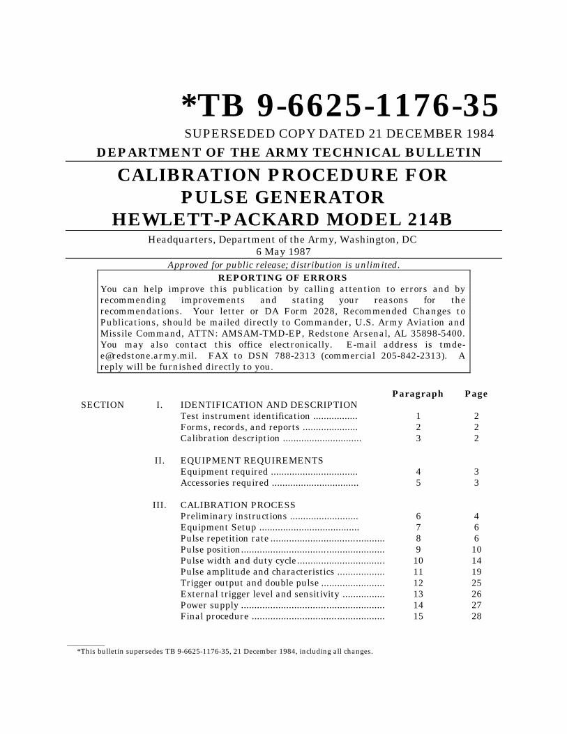
Figure 6. Variable trigger - equipment setup.
14. Power Supply
a. Performance Check
(1) Position controls as listed in (a) through (e) below:
(a) AMPLITUDE 3-10 pushbutton pressed.
(b) POLARITY switch to NEG.
(c) MODE EXT TRIG pushbutton pressed.
(d) DUTY CYCLE % pushbutton released (out).
(e) DELAY/ADVANCE DOUBLE PULSE switch to DELAY.
(2) Connect negative input of digital voltmeter (Al) to TP7 (fig. 7) and positive inputto TP1 (fig. 7) using leads (B7). Digital voltmeter will indicate approximately 155 V.Record digital voltmeter indication.
TB 9-6625-1176-35
28
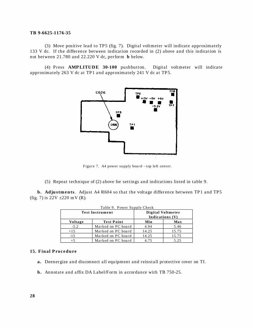
(3) Move positive lead to TP5 (fig. 7). Digital voltmeter will indicate approximately133 V dc. If the difference between indication recorded in (2) above and this indication isnot between 21.780 and 22.220 V dc, perform b below.
(4) Press AMPLITUDE 30-100 pushbutton. Digital voltmeter will indicateapproximately 263 V dc at TP1 and approximately 241 V dc at TP5.
Figure 7. A4 power supply board - top left center.
(5) Repeat technique of (2) above for settings and indications listed in table 9.
b. Adjustments. Adjust A4 R604 so that the voltage difference between TP1 and TP5(fig. 7) is 22V ±220 mV (R).
Table 9. Power Supply CheckTest Instrument Digital Voltmeter
Indications (V)Voltage Test Point Min Max
-5.2 Marked on PC board 4.94 5.46+15 Marked on PC board 14.25 15.75-15 Marked on PC board 14.25 15.75+5 Marked on PC board 4.75 5.25
15. Final Procedure
a. Deenergize and disconnect all equipment and reinstall protective cover on TI.
b. Annotate and affix DA Label/Form in accordance with TB 750-25.

TB 9-6625-1176-35
29
By Order of the Secretary of the Army:
JOHN A. WICKHAM, JR.General, United States Army
Chief Of Staff
Official:
R. L. DILWORTHBrigadier General, United States Army
The Adjutant General
Distribution:To be distributed in accordance with DA Form 12-34C, Block No. 319, requirements forcalibration procedures publications.
PIN: 0476751-000
*U S GOVERNMENT PRINTING OFFICE 1991-531-038/40233