TB 10 - GeoStructures · page two where f’c is the concrete compressive strength (psi) A factor...
16
STRUCTURAL DESIGN CONSIDERATIONS FOR UNIFORMLY - LOADED FLOOR SLABS SUPPORTED BY RAMMED AGGREGATE PIER ® ELEMENTS N o . 10 geopier foundation co inc technical bulletin This Technical Bulletin discusses the structural analysis of uniformly loaded floor slabs supported by Rammed Aggregate Pier® (RAP) soil reinforcing elements. RAP soil reinforcing elements are commonly used to support concrete floor slabs eliminating the need for structural slabs supported on deep foundations or massive excavation and recompaction required for slab-on-grade construction. The piers reduce total and differential settlements because of their high strength and high stiffness characteristics. Because of the variation in pier stiffness with respect to in-situ soil stiffness, however, the assumption of uniform sub-grade support is no longer valid. The dissimilar slab support conditions, consisting of high stiffness at the pier locations and relatively low stiffness between the piers, leads to the development of bending moments and shear stresses within the slabs under applied load. This Technical Bulletin describes the result of a series of finite element analyses performed to quantify the bending moment and shear stress conditions that develop in relatively thin floor slabs supported by RAP elements. This bulletin provides design charts that may be used to estimate required concrete slab thickness for a floor slab with a uniformly distributed loading condition supported by RAP elements. The charts should be used with judgement, however, because it is recognized that a uniformly distributed loading analysis may not capture the critical load case for the design of the slab. 1. background: design & construction options For most buildings, ground floor slabs-on-grade are typically designed using empirical standards of practice that require little engineering effort and result in relatively thin and cost-effective slab sections. Analytical methods using nomographs are also available to designers that account for non-uniform loading conditions such as truck wheel loads and storage rack leg loads. Both empirical and analytical methods assume uniform subgrade stiffness where the soil is represented as linear– elastic springs (Figure 1a), commonly known as the “Winkler” subgrade model. Using methods outlined by the Portland Cement Association and others, the design of the floor slab includes applying simulated loads to the slab and evaluating computed shear stresses and bending moments. Resulting designs can include slabs constructed from plain concrete and concrete reinforced with conventional rebar or post-tensioned strands. The design typically is based on an uncracked section and is focused on limiting the concrete tensile stress to a value that is much less than the concrete modulus of rupture or flexural cracking stress. The concrete modulus of rupture (f r ) is normally taken as: f r = 9 √ f’ c Eq.2.
Transcript of TB 10 - GeoStructures · page two where f’c is the concrete compressive strength (psi) A factor...

s t r u c t u r a l d e s i g n c o n s i d e r a t i o n s f o r u n i f o r m l y - l o a d e d f l o o r s l a b s s u p p o r t e d b y r a m m e d a g g r e g a t e p i e r ® e l e m e n t s
No.10g e o p i e r f o u n d a t i o n c o i n c
t e c h n i c a l b u l l e t i n
This Technical Bulletin discusses the structural analysis of uniformly loaded floor slabs supported by Rammed
Aggregate Pier® (RAP) soil reinforcing elements. RAP soil reinforcing elements are commonly used to support
concrete floor slabs eliminating the need for structural slabs supported on deep foundations or massive
excavation and recompaction required for slab-on-grade construction. The piers reduce total and differential
settlements because of their high strength and high stiffness characteristics. Because of the variation in pier
stiffness with respect to in-situ soil stiffness, however, the assumption of uniform sub-grade support is no
longer valid. The dissimilar slab support conditions, consisting of high stiffness at the pier locations and
relatively low stiffness between the piers, leads to the development of bending moments and shear stresses
within the slabs under applied load.
This Technical Bulletin describes the result of a series of finite element analyses performed to quantify the
bending moment and shear stress conditions that develop in relatively thin floor slabs supported by RAP
elements. This bulletin provides design charts that may be used to estimate required concrete slab thickness
for a floor slab with a uniformly distributed loading condition supported by RAP elements. The charts should
be used with judgement, however, because it is recognized that a uniformly distributed loading analysis may
not capture the critical load case for the design of the slab.
1 . b a c k g r o u n d : d e s i g n & c o n s t r u c t i o n o p t i o n s
For most buildings, ground floor slabs-on-grade are
typically designed using empirical standards of practice
that require little engineering effort and result in relatively
thin and cost-effective slab sections. Analytical methods
using nomographs are also available to designers that
account for non-uniform loading conditions such as truck
wheel loads and storage rack leg loads. Both empirical
and analytical methods assume uniform subgrade
stiffness where the soil is represented as linear–
elastic springs (Figure 1a), commonly known as the
“Winkler” subgrade model. Using methods outlined by
the Portland Cement Association and others, the design
of the floor slab includes applying simulated loads
to the slab and evaluating computed shear stresses
and bending moments. Resulting designs can include
slabs constructed from plain concrete and concrete
reinforced with conventional rebar or post-tensioned
strands. The design typically is based on an uncracked
section and is focused on limiting the concrete tensile
stress to a value that is much less than the concrete
modulus of rupture or flexural cracking stress. The
concrete modulus of rupture (fr) is normally taken as:
fr= 9 √ f’c Eq.2.
p a g e t w o
where f’c is the concrete compressive strength (psi) A
factor of safety of 1.7 is normally used in the design of
a slab-on-grade. Conventional slabs-on-grade are often
four to six-inches thick and are relatively inexpensive
to construct.
When floor slabs are to be placed on undocumented
fills, organic soils, and other compressible materials,
and excessive settlement is intolerable, the slab
design options usually consist of one of three choices:
1. Maintain the relatively thin concrete
slab-on-grade design philosophy, but only
if the unsuitable soils are excavated and
recompacted or replaced with more qualified
materials (Figure 1b). The floor slabs are
then analyzed with the Winkler subgrade
method presented above, which results
in slab sections comparable to those on
suitable soils. The added cost of this option
is related to the cost of the earthwork,
costs that can quickly become prohibitive
at sites with deep cuts, contaminated soils,
high groundwater, or adjacent structures
that must be protected or underpinned.
2. Install piles or drilled concrete caissons
to support a structural slab (i.e. a slab that
is structurally designed and reinforced to
be able to span between installed deep
foundations). A pile-supported structural
slab (Figure 1c) alone can cost as much or
more than the excavation and replacement
option. Because of the very high stiffness
ratio between the piles and the natural soils,
the piles are assumed to resist the entire
slab load and the slab must be capable
of structurally spanning between the pile
supports. In this case, the stiffness and
support of the in-situ soil between the piles
is completely disregarded in the analysis.
3. Install Rammed Aggregate Pier® (RAP)
elements to reinforce the compressible soils
and allow for the construction of a relatively
thin floor slab (Figure 1d). The piers are
installed to reinforce the poor soils at a pier
spacing that typically ranges between 8 and
15 feet on-center. Because the RAP elements
are stiffer than the surrounding soil, they
attract floor slab loads forming a non-uniform
support condition. Similar to pile-supported
structural slabs, the floors must be designed
to resist shear stresses and bending
moments that develop as the applied loads
attempt to span to the stiffer supports.
However, these stresses are significantly
lower than those for pile-supported structural
slabs because of the reduced stiffness ratio.
This Technical Bulletin focuses on the slab design
approach for the RAP design option. The construction
of RAP reinforcing elements is well described in the
literature (Lawton and Fox 1994, Fox and Cowell 1998,
Wissmann et al. 2000). Unique to the process is the
use of direct vertical ramming action on thin lifts of
placed aggregate, resulting in piers of high strength
and stiffness (Wissmann et al. 2001).
The RAP technique results in a subgrade that has a
non-uniform stiffness distribution: high stiffness at the
RAP elements and low stiffness in areas supported
by the matrix soil between the piers. Therefore, the
slab experiences shear and bending moment demands
between those experienced by a structural slab and a
slab-on-grade. Structural finite element analyses may
be used to compute induced slab bending stresses
and shear stresses. Design variables used in the finite
element analysis include imposed uniformly-distributed
area load, concrete compressive strength, RAP stiffness,
in-situ soil stiffness, RAP spacing, and slab thickness.

Figure 1d.
RAP Supported SlabW
Figure 1c.
Pile-supported SlabW
Figure 1b.
Removal & Replacement of
Compressible SoilW
Figure 1a.
“Winkler” Beam MethodW
p a g e t h r e e

p a g e f o u r
To understand the development of shear stresses and
bending moments in RAP-supported floor slabs, a suite
of structural finite element analyses was performed by
KPFF structural engineers, John P. Miller, P.E., S.E.,
Principal and Jason N. Richards, P.E., S.E., Associate.
The analyses considered the response of the slab to
uniformly-distributed loading conditions and accounted
for subgrade support by using stiff springs at the
RAP locations and relatively soft springs to represent
the matrix soil between the piers. The analyses were
performed for variations of:
• Applied uniform floor slab loading pressure
(w, expressed in psf),
• Concrete compressive strength (f’c, expressed in psi)
and corresponding stiffness characteristics,
• RAP spring stiffness (kg, expressed in psi/in),
• Matrix soil spring stiffness (km, expressed in psi/in),
• RAP spacing (L, expressed in feet), and
• Floor slab thickness (t, expressed in inches).
The results of each analysis were used to compare
the computed bottom fiber tensile stresses against
allowable values to establish the allowable value of
applied slab pressure for the modeled slab geometry
and spring support conditions. These results were
used to evaluate the maximum allowable uniformly-
distributed load (prior to the development of limiting
concrete tensile stress) for each value of normalized
slab thickness (t/L). For simplicity, the analyses
neglected stresses induced by concrete shrinkage
and slab deformations, factors thought to be mitigated
through the use of construction joints as described in
section 2.1.
2.1 f i n i t e e l e m e n t m o d e l
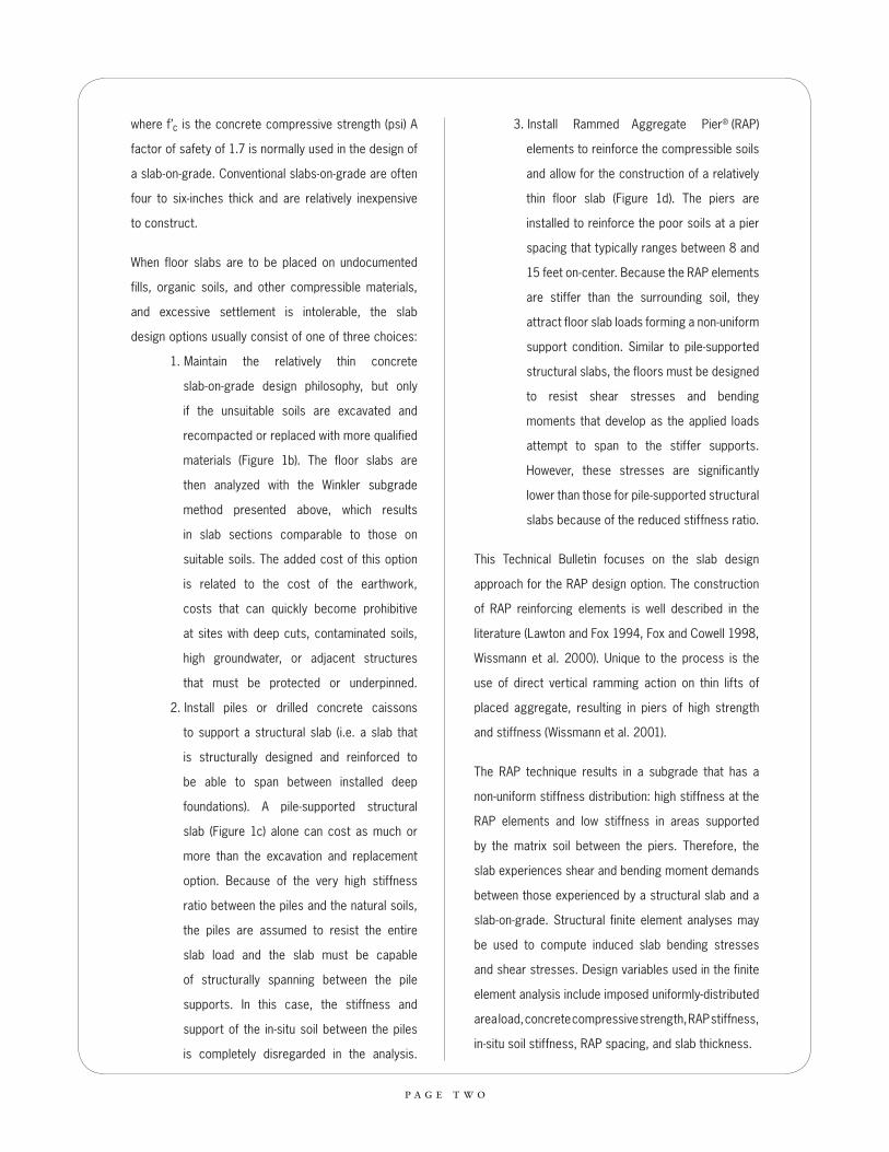
A typical bay for a building with RAP foundation and
floor slab support is shown in Figure 2. The piers
are evenly spaced between the column bays with
pier spacing determined from the characteristics of
the matrix soils, floor slab loading, thickness of the
floor slab, and slab construction joint spacing. The
piers are commonly located directly underneath the
construction joints where the joint may transfer shear
stresses but not bending moments. The hatched area
shown in Figure 3 indicates the extents of the finite
element model used in this study, bounded on two
sides by slab joints and on the opposite sides by lines
of symmetry.
RAM Concept software (RAM International 2005)
was used to perform the finite element simulations.
To model the response of the slab, hybrid shell
elements that can accommodate in-plane axial and
shearing stresses as well as out of plane bending and
shearing stresses were modeled. A concrete 28-day
compressive strength (f’c) of 4000 psi was used in
the analyses. The RAP spacing was varied from 8 feet
to 16 feet on-center in two-foot increments. Figure 3
shows the finite element mesh used for the study.
2 . n u m e r i c a l a n a l y s e s
p a g e f i v e
Figure 2.
Typical Building Bay
Figure 3.
Finite Element Mesh
Used for Analysis
4.25’

p a g e s i x
2.2 s u b g r a d e s u p p o rt
Linear-elastic springs were used to represent subgrade
support. Stiff springs (kg) were used to represent the
30-inch diameter RAP elements and relatively soft
springs (km) were used to represent the unimproved
matrix soil response. A constant RAP spring stiffness
(kg) value of 150 pci and matrix soil stiffness (km) values
ranging from 5 pci to 30 pci were used. The ratio of
the spring constants is denoted by the stiffness ratio
(Rs=kgkm
) and is a key determinant in the development
of slab bending stresses (i.e. a stiffness ratio of infinity
would result in a two-way structural slab design shown
in Figure 1c; a stiffness ratio of unity would result in a
conventional slab-on-grade design shown in Figure 1a).
Table 1 presents a summary of stiffness constants and
stiffness ratios used in the analyses.
The installation of the RAP elements increases the
lateral stresses in the matrix soil which results in
improved stiffness characteristics (Handy 2001). This
soil improvement results in a transition from the high
stiffness piers to the matrix soil elements. The stiffness
transition function that was used in the analyses was
taken from the results of plate load tests performed by
researchers at Iowa State University (White 2004).
Figures 4 through 6 present the results of the numerical
simulations for the 60 unique sets of geometry,
subgrade support, and uniform loading conditions
described in Table 1. The figures present contours
of normalized thickness ratios (t/L) required to limit
the tensile stress demands imposed by normalized
slab pressures (w/f’c) to within allowable values. The
contours shown on the figures were developed for pier
spacing varying from 8 to 16 feet on-center. A required
floor slab thickness value for various applications of
uniform slab pressure may be estimated by using the
following procedure:
1. Establish the appropriate pier to matrix
soil stiffness ratio for the project site. The
stiffness modulus of the RAP element (kg)
is typically verified with a site-specific
modulus test performed in accordance with
procedures described in Fox and Cowell
Table 1: Range of parameter values considered in this study
Parameter Values considered in this study
RAP center to center spacing (ft) 8, 10, 12, 14, and 16
RAP stiffness, kg (pci) 150
Stiffness ratio, Rs = 5, 10, and 20
Slab thickness, t (in) 4, 6, 8, and 10
kgkm
3 . r e s u l t s

1998. The matrix soil stiffness modulus (km)
is obtained by computing the settlement of
the unreinforced matrix soils in response
to the floor slab pressure, where km is the
ratio of applied pressure to computed
deflection. Note that values of km computed
using this procedure can result in values that
are significantly lower than km values often
recommended in the literature for uniformly-
supported floor slabs subjected to moving
point loads.
2. Establish the normalized loading parameter
value (w/f’c) for the project. Include the
weight of the slab when determining the floor
slab pressure, w.
3. Select a RAP element spacing.
4. For the computed normalized loading
parameter and selected RAP spacing, use
Figures 4 through 6, as appropriate, to find
the normalized required floor slab thickness
(t/L) value. Should the input value for w/f’c
result in a solution to the left of the dashed
line shown in the figures, a minimum slab
thickness of four inches should be used.
5. Estimate the required floor slab thickness (t)
in inches to appropriately resist the induced
tensile stresses by multiplying the normalized
floor slab thickness value (t/L) by the RAP
center-to-center spacing.
When using the design charts shown on Figures 4
through 6, it should be recognized that the results
of the numerical analyses are subject to limitations.
The computed values of tensile stress in the floor
slab-on-grade are developed for uniform loading
conditions only; other loading conditions and loading
patterns, such as concentrated point loads, line loads,
and “hopscotch” loading patterns, will result in different
tensile stress values that may be more critical to
acceptable slab performance. The modeled floor slabs
included the assumption that a construction joint, which
cannot transfer bending moments, is placed over the
piers. Floor slabs with differing joint orientations should
be evaluated separately. The models also excludes the
presence of engineered fill between the tops of the
RAP elements and the bottom of the floor slabs,
which would improve the uniformity of the slab support
characteristics. The analyses are based on measured
subgrade support conditions for Rammed Aggregate
Pier elements. These results should not be extended
to other types of ground improvement because
of variations in stiffness ratios and differences in the
radial soil stiffness function resulting from differences
in installation procedures.
p a g e s e v e n

p a g e e i g h t
Figure 4.
Normalized Thickness Required for Stiffness Ratio (kg /km) of 5

p a g e n i n e
Figure 5.
Normalized Thickness Required for Stiffness Ratio (kg /km) of 10
0.60

p a g e t e n
Figure 6.
Normalized Thickness Required for Stiffness Ratio (kg /km) of 20

4 . c o n c l u s i o n s
p a g e e l e v e n
Rammed Aggregate Pier soil reinforcing
elements are commonly used to support relatively
thin concrete slabs-on-grade with light to heavy slab
loads. The design of the floor slabs should consider
the non-uniform support conditions offered by the stiff
RAP reinforcing elements in contrast with the relatively
soft matrix soil between the piers. These non-uniform
support conditions may be studied using structural finite
element analyses. The results of structural numerical
analyses performed to compute the response of
uniformly-loaded concrete floor slabs supported by RAP
elements for variable pier to matrix soil stiffness ratio
values, variable pier spacing, and ranges of uniformly
applied floor slab pressures are presented in Figures 4
through 6 herein. These results provide estimated floor
slab thicknesses (t) which can adequately resist the
applied pressures without developing tensile stresses
that exceed allowable capacity. The design charts
presented herein are for uniform loading conditions
only; project-specific analyses should be performed for
other loading conditions.

© 2010 Geopier Foundation Company, Inc.
a u t h o r s
Jason Richards, KPFFJohn Miller, P.E., S.E., Principal, KPFFKord Wissmann, Ph.D., Chief Engineer, Geopier Foundation Company, Inc.
r e f e r e n c e s
Fox, N.S. and M.J. Cowell, 1998. “Geopier Soil Reinforcement Manual.” Geopier Foundation Company, Blacksburg, Virginia.
Handy, R.L. 2001. “Does Lateral Stress Really Influence Settlement?” ASCE Journal of Geotechnical and Geoenvironmental Engineering. July.
Lawton, E.C. and N.S. Fox 1994. “Settlement of Structures Supported on Marginal or Inadequate Soils Stiffened with Short Aggregate Piers.” Proceedings, Vertical and Horizontal Deformations of Foundations and Embankments. College Station, TX. June 16-18.
RAM International 2005. “RAM Concept Analysis Software”, a trademark of RAM International, Copyright 2005, Structural Concrete Software, Inc.
White, D.J. 2004. “Subgrade Ramp Function.” Letter to Geopier Foundation Company describing results of plate load tests data. October 19.
Wissmann, K.J., N.S. Fox, and J.P. Martin, 2000. “Rammed Aggregate Piers Defeat 75-foot Long Driven Piles.” Proceedings, Performance Confirmation of Constructed Geotechnical Facilities. ASCE Special Publication No. 194. Amherst, MA. April 9-12.
a c k n o w l e d g e m e n t s
Greg Gear, P.E., GFC - Midwest, Inc. Rimas Veitas, P.E., Veitas and Veitas Engineers, Inc.
Geopier®, Rammed Aggregate Pier®, Impact® and Intermediate Foundation® are registered trademarks of Geopier Foundation Company. The Rammed Aggregate Pier systems are protected under U.S. Patent Nos. 6,425,713; 6,688,815; 6,988,855; 5,249,892; 7,226,246; 6,354,766; 7,004,684; 6,354,768; 7,326,004 and other patents pending. The information contained herein has been carefully compiled by Geopier Foundation Company and to the best of its knowledge accurately represents RAP product use in the applications, which are illustrated. Printed in the U.S.A.

s y m b o l s u s e d
f’c = concrete compressive strength
fr = concrete modulus of rupture
kg = Rammed Aggregate Pier element spring stiffness
km = Matrix soil spring stiffness
L = Rammed Aggregate Pier spacing
Rs = stiffness ratio of spring constants (kg/km)
t = floor slab thickness
w = applied uniform floor slab pressure


Geopier Foundation Company, Inc.150 Fairview Road, Suite 335Mooresville, NC 28117
Telephone: (704) 799.3185 or (800) 371.7470Fax: (704) 799.3235
e-mail: [email protected]

02_2012
Geopier Foundation Company, Inc.
800.371.7470www.geopier.com


![[Engelberg] Compressive Sensing](https://static.fdocuments.in/doc/165x107/55cf9985550346d0339dc8ee/engelberg-compressive-sensing.jpg)