SUMO GROUP PLC (“Sumo Group”, the “Group” or the “Company ...
description
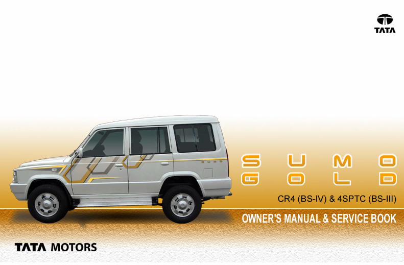

TATATATATATTTTTA SUMO GOLDA SUMO GOLDA SUMO GOLDA SUMO GOLDA SUMO GOLDCR-4 (BS-IV) & 4SPTC (BS-III)
Owner’s Manual & Service Book
TATA Motors LimitedMumbai Pune
The contents given in this book are not binding, subject to change without notice and are for illustration purpose only.
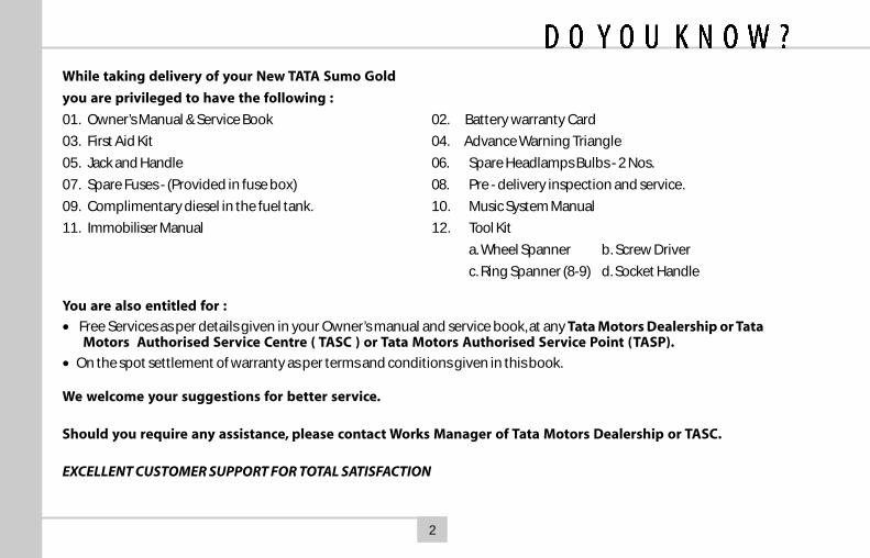
While taking delivery of your New TATA Sumo Gold
you are privileged to have the following :
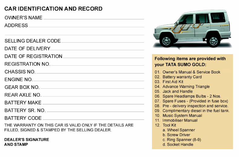
01. Owner’s Manual & Service Book 02. Battery warranty Card
03. First Aid Kit 04. Advance Warning Triangle
05. Jack and Handle 06. Spare Headlamps Bulbs - 2 Nos.
07. Spare Fuses - (Provided in fuse box) 08. Pre - delivery inspection and service.
09. Complimentary diesel in the fuel tank. 10. Music System Manual
11. Immobiliser Manual 12. Tool Kit
a. Wheel Spanner b. Screw Driver
c. Ring Spanner (8-9) d. Socket Handle
You are also entitled for :
• Free Services as per details given in your Owner’s manual and service book, at any Tata Motors Dealership or TataMotors Authorised Service Centre ( TASC ) or Tata Motors Authorised Service Point (TASP).
• On the spot settlement of warranty as per terms and conditions given in this book.
We welcome your suggestions for better service.
Should you require any assistance, please contact Works Manager of Tata Motors Dealership or TASC.
EXCELLENT CUSTOMER SUPPORT FOR TOTAL SATISFACTION
2
Dear Customer,
Thank you for choosing the Tata Sumo Gold another quality offering from thecompany’s growing range of passenger vehicles.
We would request you to get acquainted with the details in this owner’s manual,which will enable you to derive optimum performance from your Tata Sumo gold.We look forward to having you as a satisfied customer and hope to have you retain usas your first choice for any of your motoring needs.
We are privileged to have you as our customer.

FOREWORDThank you for selecting TATA Sumo Gold vehicle of your choice.
We welcome you to the world of advanced automotiveengineering in a form especially suited to our operatingconditions.
This book gives you all the information necessary for makingyour ownership of the vehicle, a thoroughly satisfyingexperience.
To assist you in maintaining your vehicle as per recommendedschedule, we have a widespread network of dealers and servicecentres. The list is included in this book for your convenience.
Should you need any special assistance, please call on ourAuthorised dealer.
Please note that by adhering to the correct operating proceduresand by availing the scheduled maintenance services at ourauthorised service outlets, you can obtain the maximumperformance from your vehicle.
We request you to go through the book and drive manymiles of motoring pleasure.
We provide safe, high quality, high performance vehicles. In orderto maintain the level of performance and reliability in the vehicle,it is important that only Tata motors genuine accessories are tobe fitted. Any accessory that is fitted or modification that iscarried out without authorisation can hamper the safety andperformance of the vehicle besides depriving you of yourwarranty benefits.
Use of genuine parts, designed and manufactured to ourexacting standards, are the best way to maintain your vehiclein peak operating condition. Please do not use substitutes.They always prove costlier in the long run.Failure to use genuine parts can invalidate any future warrantyclaims.
The information and specification given in this book are validas on the date of printing. Tata Motors reserves the right tomake changes in design and specifications and / or to makeadditions to or improvements in this product without obligationto install them on products previously sold.
3
FOREWORD 3
ENVIRONMENT PROTECTION 6
WARRANTY TERMS & 8CONDITION
DO'S 10
DONT'S 13
AGGREGATE NUMBERING 14
HANDLING
Key 16
Anti-theft Device 16
Door Locking 17
Manual Window Winding 17
Power Windows 18
Sun Visors 19
Outer Rear View Mirrors 20
Inner Rear View Mirror 20
Driver's & Co-driver's Seat 21
Middle Seat 22
Seats at Rear 22
Seat Belt 23
Head restraint 25
Driving Controls 26
Instrument Panel 27
Indicators 30
Gauges 34
Steering Lock Cum IgnitionSwitch 35
Combi-Switch 37
Music System 39
Engine Compartment Lamp 39
Tail Lamp 40
Registration Plate lamp 40
High Mounted Stop Lamp 40
Interior Roof Lamps 41
Headlamp Leveling Switch 42
Accessory Switches 43
Power Socket 46
Ash Tray 46
Bonnet Opening & Closing 47
Fuel Flap Opening 47
Gear Shift lever 48
Spare Wheel 49
Jack & Tools 50
Parking Brake 50
Catalytic Converter 51
EGR System 51
Turbocharger 52
Power Steering 53
Air Conditioning 55
Preparing the vehicle for thedrive 58
DRIVING INSTRUCTION
Driving Instruction 61
Braking 62
Fuel Economy 62
Driving on Snowy or Icy Roads 63
Driving on Sandy or MuddyRoads 63
Driving Through Water 64
Driving on a Rainy Day 64
4
Driving at Night 65
Driving Climbing SharpGradients 65
Driving Descending SharpGradients 66
Towing the Vehicle 67
Driving Safety 68
Safety Checks 68
VEHICLE MAINTENANCE
Engine Compartment 70
Changing Engine Oil 72
Changing Oil Filter 72
Engine Air Filter 73
Fuel Filter & Priming CR-4 74
Fuel Filter & Priming 4SPTC 74
Fan Belt Tension Adjustment 75
Brake Clutch System Bleeding 76
Cooling System 77
Brake System 78
Brake Adjustment 81
Wheels & Tyres 82
Wheel Change 82
Wheel Alignment 82
Tyre Pressure 82
Wheel Balancing 83
Replacing Tyre / Tube 83
Replacing Tyre / Rim 83
Tyre Rotation 84
Headlamps 84
Head Lamp Adjustment 84
Head Lamp Bulb Replacement 86
Bulb Specification 87
Fuses 88
Vehicle Care 89
FUEL, LUBRICANTS & COOLANTS
Fuel 92
Lubricants 93
Coolants 93
Recommended Oils, Lubricants 94
TECHNICAL SPECIFICATIONS 95
SPECIAL INSTRUCTIONS 99
SERVICE SCHEDULE 101
RECORD OF SERVICEPERFORMED 105
ABBREVIATIONS 108
ALPHABETICAL INDEX 109
5
6
TATA MOTORS is committed toproduce vehicles usingenvironmentally sustainabletechnology. A number of featureshave been incorporated in TataMotors Passenger Car Vehicleswhich have been designed to ensureenvironmental compatibilitythroughout the life cycle of thevehicle. We would like to inform youthat your vehicle meets Emissionnorms and this is being regularlyvalidated at the stage ofmanufacturing.
As a user, you too can protect theenvironment by operating yourvehicle in a pro-active manner. A lotdepends on your driving style and theway you maintain your vehicle. We aregiving below a few tips for yourguidance.
Driving
Avoid frequent and violentaccelerations.
Do not carry any unnecessaryweight on the vehicle as itoverloads the engine. Avoidusing devices requiring highpower consumption during slowtraffic condition.
Monitor the cars fuelconsumption regularly and if itshows a rising trend, get the carimmediately attended at ourAuthorised Service Centre.
Switch off the engine duringlong stops at traffic jams orsignals. If the situation demandsthat engine be kept running,avoid frequent revving up of theengine. Also avoid frequentstopping and restarting, ifuncalled for.
It is not necessary to rev up theengine before turning it off as itunnecessarily burns the fuel.
Shift to higher gears as soon aspossible. Use each gear upto 2/3rdof its maximum engine speed. Achart indicating gear shiftingspeed is given in this book.
Maintenance of the vehicle
Ensure that recommendedmaintenance is carried out on thevehicle regularly at ourAuthorised Service Outlets.
As soon as you see any leakagesof oil or fuel in the car, get itattended immediately.
Use only recommended brandsand grades of lubricants and cleanuncontaminated fuels.
Get your vehicle checked foremission periodically by
ENVIRONMENTAL PROTECTION
7
authorised dealer and regularlyrenew the P.U.C. certificate.
Ensure that fuel filter, oil filter andbreathers are periodicallychecked and if required, replacethe same by only genuine TataMotor’s recommended brands.
Do not pour used oils or coolantsinto the sewage drains, garden soilor open streams. Dispose the usedfilters and batteries in compliancewith the current legislation.
l Do not allow any unauthorisedperson to tamper with enginesettings or to carry modificationson the vehicle.
l Never allow the vehicle to run outof fuel.
Parts like brake liners, clutch discshould be vacuum cleaned. Do notuse the compressed air forcleaning these parts which mayspread the dust in the atmosphere.
While carrying out the servicingor repairs on your vehicle, youshould pay keen attention tosome of the importantaggregates, which greatly affectemission. These components are :
1. Fuel injection pump, Injectors/Nozzles
2. Air intake & Exhaust systemespecially for leakages
3. Cylinder head for valve leakage
4. All filters such as air, oil and fuelfilters (check periodically)
5. Turbocharger and intercooler(if fitted)
6. Catalytic converter (if fitted)
7. EGR System and components
8. Electrical Connections for EGR
ENVIRONMENTAL PROTECTION
This Owner’s Manual contains furtherinformation on driving precautionsand maintenance care leading toenvironment protection. Pleasefamiliarise yourself with these aspectsbefore driving.
8
We WARRANT each TATA SUMOGOLD vehicles & parts thereofmanufactured by us to be free fromdefect in material and workmanship,subject to the following terms &conditions :1. The warranty for the vehicle shall
be for 36 months from the dateof sale of the vehicle OR1,00,000 kms, whichever isearlier.
2. Our obligation under this warrantyshall be limited to repairing orreplacing, free of charge, suchparts of the vehicle which, in ouropinion, are defective, on thevehicle being brought to us or toour dealers within the warrantyperiod. The parts so repaired orreplaced shall also be warrantedfor quality and workmanship butsuch warranty shall be co-terminus with this original warranty.
3. Any part which is found to bedefective and is replaced by usunder the warranty shall be ourproperty.
4. As for such parts as tyres,batteries & electrical equipment,fuel injection equipment, powersteering equipment, A/C equipment& anti-theft device notmanufactured by us but suppliedby other parties, this warrantyshall not apply, but buyers of thevehicle shall be entitled to, so faras permissible by law, all suchrights as we may have againstsuch parties under their warrantiesin respect of such parts. OurDealers/TASC’s will assist thepurchaser in taking up thecomplaint with the respectivemanufacturers and their decisionon the warranty will be final.
5. This warranty shall not apply if thevehicle or any part thereof isrepaired or altered otherwise thanin accordance with our standardrepair procedure, or by any personother than our sales or serviceestablishments, our authoriseddealers or service centres orservice points in any way so as,
in our judgement which shall befinal and binding, to effect itsreliability, nor shall it apply if, inour opinion which shall be final andbinding the vehicle is subjected tomisuse, negligence, improper orinadequate maintenance oraccident or loading in excess ofsuch carrying capacity as certifiedby us, or such services asprescribed in our Owner’s Manualand Service Book are not carriedout by the buyer through our salesor service establishments, ourauthorised dealers or servicecentres or service points.
6. This warranty shall not covernormal wear and tear or anyinherent normal deterioration of thevehicle or any of its parts arisingfrom the actual use of the vehicleor any damage due to negligentor improper operation or storageof the vehicle. This warranty shallnot apply to normal maintenanceservices viz. oils & fluid changes,head lamps focussing, fastener
TERMS AND CONDITIONS
9
retightening, wheel balancing, tyrerotation, adjustment of valveclearance, fuel timing, ignitiontiming and consumables likebulbs, fuel filters and oil filters etc.This warranty shall not apply toany damage or deteriorationcaused by environmental pollutionor bird droppings. This warrantyshall not apply to V-belts, hosesand gas leaks in case of airconditioned vehicle. Slightirregularities not recognised asaffecting the function or quality ofthe vehicle or parts, such as slightnoise or vibration, defectsappearing only under particular orirregular operations are itemsconsidered characteristic of thevehicle.
7. This warranty shall be null and voidif the vehicle is subjected toabnormal use such as rallying,racing or participation in any othercompetitive sports. This warrantyshall not apply to any repairs orreplacement as a result of accidentor collision.
8. This warranty is expressly in lieuof all warranties, whether by lawor otherwise, expressed orimplied, and all other obligationsor liabilities on our part and weneither assume nor authorise anyperson to assume on our behalf,any other liability arising from thesale of the vehicle or anyagreement in relation thereto.
9. The buyer shall have no otherrights except those set out aboveand have, particular, no right torepudiate the sale, or anyagreement or to claim anyreduction in the purchase priceof the vehicle, or to demand anydamages or compensation forlosses, incidental or indirect, orinconvenience or consequentialdamages, loss of vehicle, or lossof time, otherwise, incurred oraccrued.
10.Any claim arising from thiswarranty shall be recognised onlyif it is notified in writing to us or toour concerned dealer without any
delay soon after such defect ascovered and ascertained under thiswarranty.
11.This warranty shall standterminated if the vehicle istransferred or otherwise alienatedby the buyer without our priorwritten consent.
12.We reserve our rights to make anychange or modification in thedesign of the vehicle or its partsor to introduce any improvementtherein or to incorporate in thevehicle any additional part oraccessory at any time withoutincurring any obligation toincorporate the same in thevehicles previously sold.
TERMS AND CONDITIONS
10
1. Use recommended oils andlubricants only.
2. Change oil in engine, gear box,steering system and rear axle atprescribed intervals.
3. Use only genuine oil filter andfuel filter elements. Replace themat regular intervals.
4. Clean air filter elementregularly. Replace filter elementwhen service indicator shows redband even after cleaning the filterelement.
5. Ensure periodic servicing as permaintenance schedule.
6. Insist on use of genuine spare parts.
7. Ensure that caps of auxiliary tankand radiator are firmly fitted tokeep the cooling system pressurisedand to maintain coolant level.Always use genuine radiator cap
only of 1.0 kg/cm2 (14 PSI),for replacement.
8. Check tyres for damage from timeto time and remove any foreignbodies embedded in treads.
In case of tyre replacement or repairsdue to puncture have the wheelbalanced Keep grease, oil and fuelaway from the tyres. In case ofuneven tyre wear get the vehicleattended to by any of our authorisedservice set-ups.
9. Maintain correct tyre pressure.
10. Check battery every week and topup electrolyte level. Keep batteryterminals clean and cable joints tight.Apply vaseline / petroleum jelly onterminals. Use distilled water only fortopping up.
11. Observe correct polarity whenconnecting battery terminals.
Do’s
11
Do’s12. Disconnect alternator terminals
while carrying out any welding onthe vehicle.
13. Avoid panic braking. Use lower gearswhile descending gradients.
14. Start the vehicle always in the 1stgear to avoid premature clutch wear.
15. Keep both foot and parking brakesproperly adjusted.
16 Before engaging reverse gear,ensure that vehicle has come to astop, declutch, wait for a few secondsand shift into reverse gear.
17. When parking on slopes, use wheelchocks, apply parking brake andkeep vehicle in low gear.
18. In case of emergency parking orbreakdown on road, push thehazard warning switch to flash allthe blinker lights to warn other roadusers.
19. Release parking brake beforedriving off.
20. Release the ignition key as soonas engine starts.
21. Retighten wheel mounting nutsafter 100 km of every wheel change.Tightening Torque : 12 -15 mkg.
22. Use only recommended FUSES andalways keep spare fuses in the box.
23. In case of engine not startingfirst check the fuse of fuelinjection pump solenoid.
24. Ensure doors are properly closed.
25. If your vehicle has aturbocharged engine, keepengine at idling speed foratleast a minute after startingand also before stopping it, toprotect the turbocharger againstdamage due to oil starvation.
12
Where Air conditioning system isinstalled
1. After parking in the sun, drive withwindows rolled down for a fewminutes to blow off hot air beforeswitching on A/C.
2. Keep all windows rolled-up whenAC system is working.
3. During stop and go city drivinguse lower gears to obtain efficientcooling.
4. If you feel irritation in the eyes dueto smoke or during long drive, stopA/C and ventilate for half a minuteby winding down door glasses or usefresh air mode provided with HVACsystem.
5. Before stopping the engine firstswitch “OFF’ A/C and then the blower.
Do’s
6. During off-season operate the airconditioner a few times every monthto lubricate components.
13
Dont’s1. Do not use Clutch Pedal as Foot
Rest. This will reduce clutch life.
2. Do not Coast vehicle in Neutraland engine switched-off position.This is a safety hazard.
3. Do not run engine withoutRadiator Cap. Use genuine Caponly, to keep system pressurised.
4. Do not overtighten engine oilfilter.
5. Front and rear suspension shockabsorbers fitted on this vehicle havein-built rebound stopper. There is noseparate rebound stopper fitted onthe vehicle. Hence, do not drive thevehicle either without shockabsorbers OR with non-genuineshock absorbers, otherwisesuspension is likely to be damaged.
6. If your vehicle has a turbochargedengine, do not stop the engine atonce, allow it to run at idling speedfor atleast 1 minute. Also do notaccelerate engine till the engine oilpressure has built up.
7. Do not cause heating of A/C pipe(where fitted), while welding/brazing in its viscinity.
8. Do not disturb the fast idling controldevice actuator setting, where fitted.
9. Do not open any hose/pipe pointsof A/C system (where fitted).
10. Do not put your hand inside thecondenser fan when the grille isremoved. Disconnect power supplyto fan and switch off engine beforeany maintenance work, whereapplicable.
11. Do not open HP system under anycondition. It should be handled bytrained professional only. (i.e. HPPump, Rail, Injector, HP lines)
12. Do not clean EngineCompartment with high pressurewater jet. It can causeMalfunctioning of electroniccomponents. Cleaning can bedone with high pressure air.
14
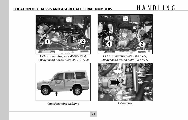
LOCATION OF CHASSIS AND AGGREGATE SERIAL NUMBERS
1. Chassis number plate (4SPTC- BS-III)2. Body Shell (Cab) no. plate (4SPTC- BS-III)
FIP numberChassis number on frame
1. Chassis number plate (CR-4 BS-IV)2. Body Shell (Cab) no. plate (CR-4 BS-IV)
15
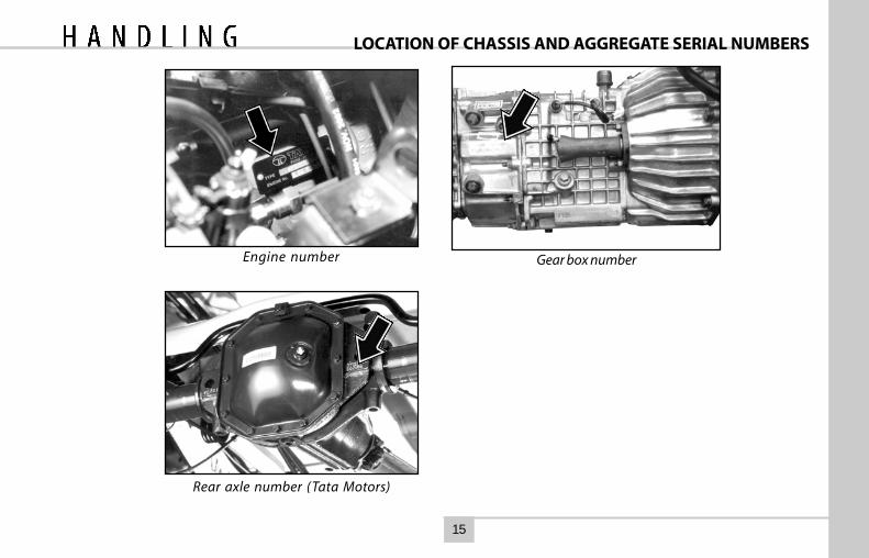
LOCATION OF CHASSIS AND AGGREGATE SERIAL NUMBERS
Rear axle number (Tata Motors)
Gear box numberEngine number
16
KEY & CENTRAL DOOR LOCKING
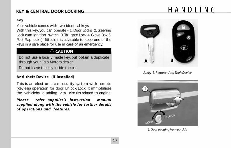
Key
Your vehicle comes with two identical keys.With this key, you can operate - 1. Door Locks 2. SteeringLock cum Ignition switch 3. Tail gate Lock 4. Glove Box 5.Fuel Flap lock (if fitted). It is advisable to keep one of thekeys in a safe place for use in case of an emergency.
CAUTION
Do not use a locally made key, but obtain a duplicatethrough your Tata Motors dealer.
Do not leave the key inside the car.
Anti-theft Device (if installed)
This is an electronic car security system with remote(keyless) operation for door Unlock/Lock. It immobilisesthe vehicleby disabling vital circuits related to engine.
Please refer supplier’s instruction manualsupplied along with the vehicle for further detailsof operations and features.
A. Key B. Remote - Anti Theft Device
A B
1. Door opening from outside
1
17
DOOR LOCKING & WINDOW WINDING
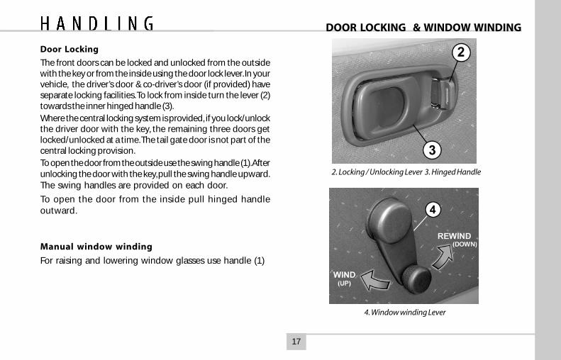
2. Locking / Unlocking Lever 3. Hinged Handle
4. Window winding Lever
Door Locking
The front doors can be locked and unlocked from the outsidewith the key or from the inside using the door lock lever. In yourvehicle, the driver’s door & co-driver’s door (if provided) haveseparate locking facilities. To lock from inside turn the lever (2)towards the inner hinged handle (3).Where the central locking system is provided, if you lock/unlockthe driver door with the key, the remaining three doors getlocked/unlocked at a time. The tail gate door is not part of thecentral locking provision.To open the door from the outside use the swing handle (1). Afterunlocking the door with the key, pull the swing handle upward.The swing handles are provided on each door.
To open the door from the inside pull hinged handleoutward.
Manual window winding
For raising and lowering window glasses use handle (1)
18
POWER WINDOWS
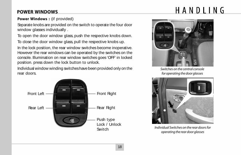
Power Windows : (if provided)
Separate knobs are provided on the switch to operate the four doorwindow glasses individually .
To open the door window glass, push the respective knobs down.
To close the door window glass, pull the respective knobs up.
In the lock position, the rear window switches become inoperative.However the rear windows can be operated by the switches on theconsole. Illumination on rear window switches goes ‘OFF’ in lockedposition. press down the lock button to unlock.
Individual window winding switches have been provided only on therear doors.
Switches on the central consolefor operating the door glasses
Individual Switches on the rear doors foroperating the rear door glasses
Front Right
Rear Right
Front Left
Rear Left
Push typeLock / UnlockSwitch
19
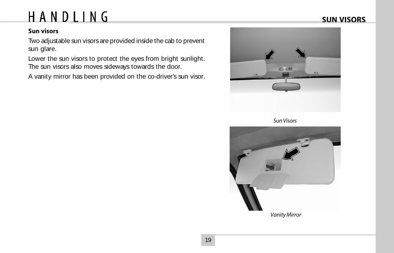
SUN VISORSSun visors
Two adjustable sun visors are provided inside the cab to preventsun glare.
Lower the sun visors to protect the eyes from bright sunlight.The sun visors also moves sideways towards the door.
A vanity mirror has been provided on the co-driver’s sun visor.
Vanity Mirror
Sun Visors
20
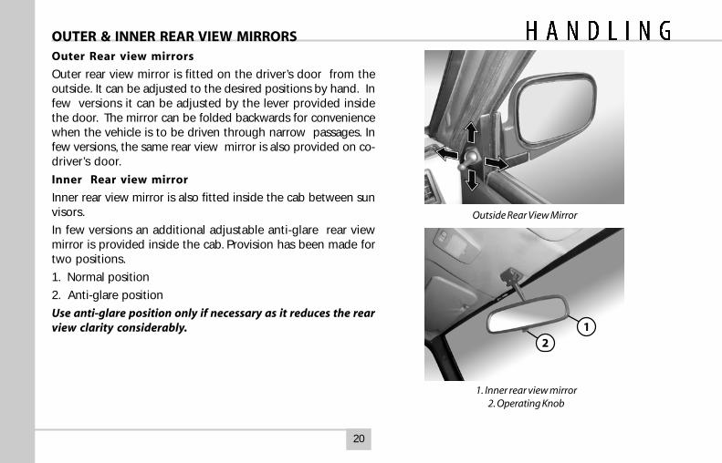
OUTER & INNER REAR VIEW MIRRORSOuter Rear view mirrors
Outer rear view mirror is fitted on the driver’s door from theoutside. It can be adjusted to the desired positions by hand. Infew versions it can be adjusted by the lever provided insidethe door. The mirror can be folded backwards for conveniencewhen the vehicle is to be driven through narrow passages. Infew versions, the same rear view mirror is also provided on co-driver’s door.
Inner Rear view mirror
Inner rear view mirror is also fitted inside the cab between sunvisors.
In few versions an additional adjustable anti-glare rear viewmirror is provided inside the cab. Provision has been made fortwo positions.
1. Normal position
2. Anti-glare position
Use anti-glare position only if necessary as it reduces the rearview clarity considerably.
Outside Rear View Mirror
1. Inner rear view mirror2. Operating Knob
12
21
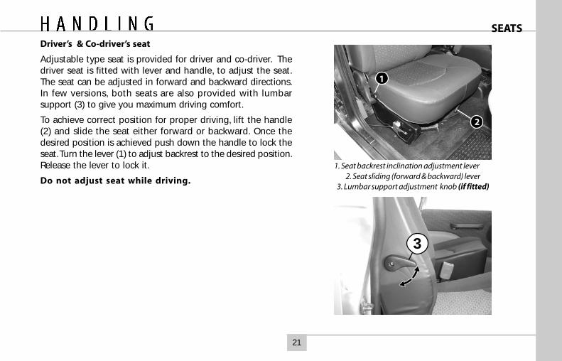
SEATSDriver’s & Co-driver’s seat
Adjustable type seat is provided for driver and co-driver. Thedriver seat is fitted with lever and handle, to adjust the seat.The seat can be adjusted in forward and backward directions.In few versions, both seats are also provided with lumbarsupport (3) to give you maximum driving comfort.
To achieve correct position for proper driving, lift the handle(2) and slide the seat either forward or backward. Once thedesired position is achieved push down the handle to lock theseat. Turn the lever (1) to adjust backrest to the desired position.Release the lever to lock it.
Do not adjust seat while driving.
1. Seat backrest inclination adjustment lever2. Seat sliding (forward & backward) lever
3. Lumbar support adjustment knob (if fitted)
3
1
2
22
SEATS
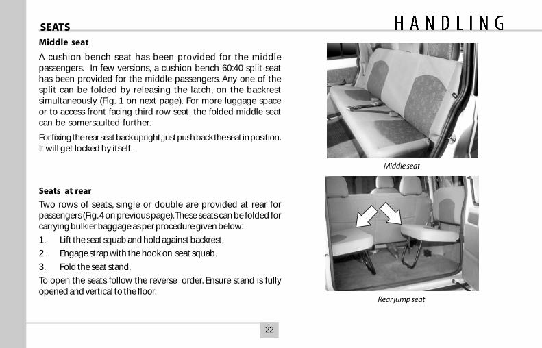
Middle seat
Middle seat
A cushion bench seat has been provided for the middlepassengers. In few versions, a cushion bench 60:40 split seathas been provided for the middle passengers. Any one of thesplit can be folded by releasing the latch, on the backrestsimultaneously (Fig. 1 on next page). For more luggage spaceor to access front facing third row seat, the folded middle seatcan be somersaulted further.
For fixing the rear seat back upright, just push back the seat in position.It will get locked by itself.
Seats at rear
Two rows of seats, single or double are provided at rear forpassengers (Fig. 4 on previous page). These seats can be folded forcarrying bulkier baggage as per procedure given below:
1. Lift the seat squab and hold against backrest.
2. Engage strap with the hook on seat squab.
3. Fold the seat stand.
To open the seats follow the reverse order. Ensure stand is fullyopened and vertical to the floor.
Rear jump seat
23
SEAT BELT
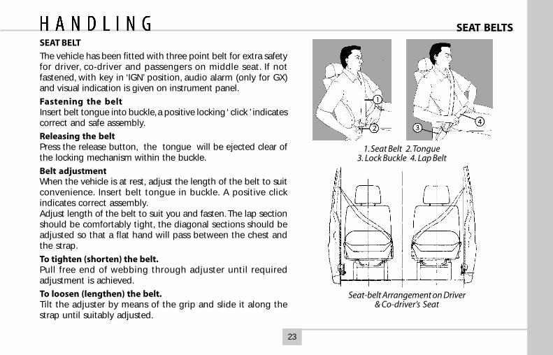
The vehicle has been fitted with three point belt for extra safetyfor driver, co-driver and passengers on middle seat. If notfastened, with key in ‘IGN’ position, audio alarm (only for GX)and visual indication is given on instrument panel.
Fastening the beltInsert belt tongue into buckle, a positive locking ‘ click ’ indicatescorrect and safe assembly.
Releasing the beltPress the release button, the tongue will be ejected clear ofthe locking mechanism within the buckle.
Belt adjustmentWhen the vehicle is at rest, adjust the length of the belt to suitconvenience. Insert belt tongue in buckle. A positive clickindicates correct assembly.Adjust length of the belt to suit you and fasten. The lap sectionshould be comfortably tight, the diagonal sections should beadjusted so that a flat hand will pass between the chest andthe strap.
To tighten (shorten) the belt.Pull free end of webbing through adjuster until requiredadjustment is achieved.
To loosen (lengthen) the belt.Tilt the adjuster by means of the grip and slide it along thestrap until suitably adjusted.
1. Seat Belt 2. Tongue3. Lock Buckle 4. Lap Belt
Seat-belt Arrangement on Driver& Co-driver’s Seat
SEAT BELTS
24
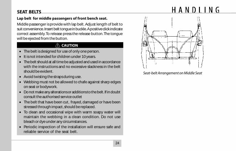
Lap belt for middle passengers of front bench seat.
Middle passenger is provide with lap belt. Adjust length of belt tosuit convenience. Insert belt tongue in buckle. A positive click indicatecorrect assembly. To release press the release button. The tonguewill be ejected from the button.
CAUTION
• The belt is designed for use of only one person.• It is not intended for children under 10 years.• The belt should at all time be adjusted and used in accordance
with the instructions and no excessive slackness in the beltshould be evident.
• Avoid twisting the straps during use.• Webbing must not be allowed to chafe against sharp edges
on seat or bodywork.• Do not make any alterations or additions to the belt. If in doubt
consult the authorised service outlet• The belt that have been cut, frayed, damaged or have been
stressed through impact, should be replaced.• To clean and occasional wipe with warm soapy water will
maintain the webbing in a clean condition. Do not usebleach or dye under any circumstances.
• Periodic inspection of the installation will ensure safe andreliable service of the seat belt.
Seat-belt Arrangement on Middle Seat
SEAT BELTS
25
Adjustable Headrestraint
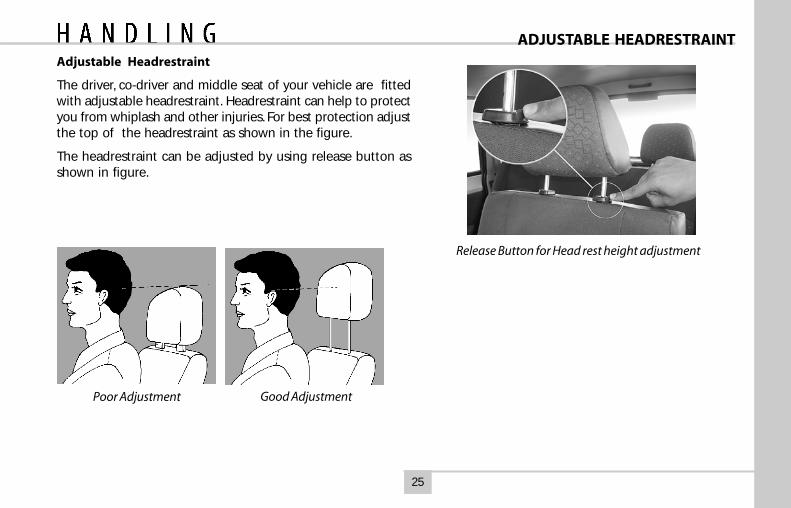
The driver, co-driver and middle seat of your vehicle are fittedwith adjustable headrestraint. Headrestraint can help to protectyou from whiplash and other injuries. For best protection adjustthe top of the headrestraint as shown in the figure.
The headrestraint can be adjusted by using release button asshown in figure.
Poor Adjustment
Release Button for Head rest height adjustment
ADJUSTABLE HEADRESTRAINT
Good Adjustment
26
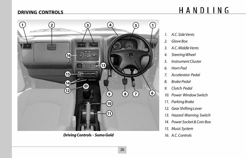
1. A.C. Side Vents
2. Glove Box
3. A.C. Middle Vents
4. Steering Wheel
5. Instrument Cluster
6. Horn Pad
7. Accelerator Pedal
8. Brake Pedal
9. Clutch Pedal
10. Power Window Switch
11. Parking Brake
12. Gear Shifting Lever
13. Hazard Warning Switch
14. Power Socket & Coin Box
15. Music System
16. A.C. ControlsDriving Controls - Sumo Gold
DRIVING CONTROLS
1 2 3 4 5 1
789 6
10
11
12
13
16
14
15
27
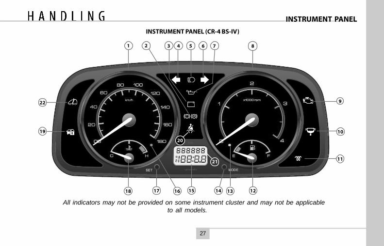
INSTRUMENT PANEL (CR-4 BS-IV)
INSTRUMENT PANEL
All indicators may not be provided on some instrument cluster and may not be applicableto all models.ca
542 3 7
20
21
81 6
9
10
11
12131415161718
19
22
28
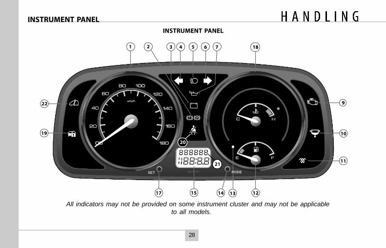
All indicators may not be provided on some instrument cluster and may not be applicableto all models.ca
INSTRUMENT PANEL
INSTRUMENT PANEL
542 3 7
20
181 6
9
10
11
1213141517
19
21
22
29
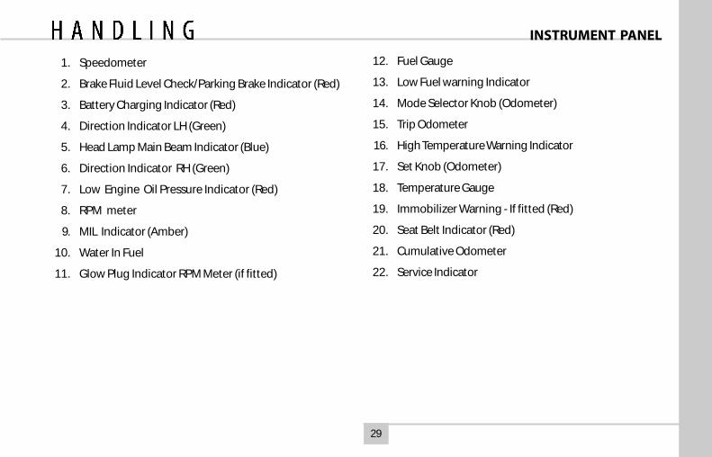
1. Speedometer
2. Brake Fluid Level Check/Parking Brake Indicator (Red)
3. Battery Charging Indicator (Red)
4. Direction Indicator LH (Green)
5. Head Lamp Main Beam Indicator (Blue)
6. Direction Indicator RH (Green)
7. Low Engine Oil Pressure Indicator (Red)
8. RPM meter
9. MIL Indicator (Amber)
10. Water In Fuel
11. Glow Plug Indicator RPM Meter (if fitted)
12. Fuel Gauge
13. Low Fuel warning Indicator
14. Mode Selector Knob (Odometer)
15. Trip Odometer
16. High Temperature Warning Indicator
17. Set Knob (Odometer)
18. Temperature Gauge
19. Immobilizer Warning - If fitted (Red)
20. Seat Belt Indicator (Red)
21. Cumulative Odometer
22. Service Indicator
INSTRUMENT PANEL
30
INDICATORS
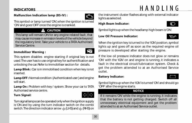
Malfunction Indication lamp (BS-IV) :
This symbol or lamp turned ‘ON’, when the ignition is turned‘ON’ and goes ‘OFF’ once the engine is cranked.
CAUTION
This lamp will remain ON for any engine related fault, thatmay cause increase in emission levels of the vehicle beyondthe regulatory limit. Take your vehicle to a TATA AuthorisedService Centre.
Immobiliser Warning :
This system disables engine starting if original key is notused.The user has to use original key for authentification andunlocking the car. Refer to Immobiliser section for details.
Lamp Blink : Car is in immobilised condition when key is notinserted.
Lamp OFF : Normal condition (Authenticated user ) and enginewill start.
Lamp On : Problem with key / system. Show your car to TATAAuthorised service centre.
Turn Signal:
Turn signal lamps can be operated only when the ignition supplyis ‘ON and by using the turn indicator switch on the combiswitch. The direction indicator arrow (LHS) and (RHS) on
the instrument cluster flashes along with external indicatorlights as selected.
High Beam Indicator:
Symbol lights up when the headlamp high beam is ‘ON’.
Low Oil Pressure Indicator:
When the ignition key is turned to the ‘IGN’ position, symbollights up and goes off as soon as the required engine oilpressure is developed after starting the engine.
If the low oil pressure indicator does not glow or remains‘ON‘ with the ‘IGN’ on and engine is running, it indicates afault in the electrical circuit/lubrication system. Check &get the problem attended to at an Authorised Serviceoutlet.
Battery Indicator:
Symbol lights up when the ‘IGN’ is turned ‘ON’ and should go‘OFF‘ after the engine starts.
NOTICE
If it remains ‘ON’ while the engine is running. It indicatesthat the battery is not getting charged. Switch off allunnecessary electrical equipment and get the problemattended to at an Authorised Service outlet.
31
INDICATORSexceeds a speed of 20 kmph. After that, it will remaincontinuously ON accompanied by a buzzer that will buzzapproximately for 100 seconds. After that, the buzzer goes OFFbut the indicator continues to remain ON.
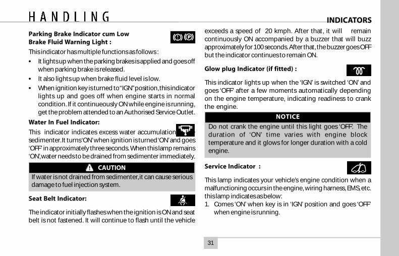
Glow plug Indicator (if fitted) :
This indicator lights up when the ‘IGN’ is switched ‘ON’ andgoes ‘OFF’ after a few moments automatically dependingon the engine temperature, indicating readiness to crankthe engine.
NOTICE
Do not crank the engine until this light goes ‘OFF’. Theduration of ‘ON’ time varies with engine blocktemperature and it glows for longer duration with a coldengine.
Service Indicator :
This lamp indicates your vehicle’s engine condition when amalfunctioning occurs in the engine, wiring harness, EMS, etc.this lamp indicates as below:1. Comes ‘ON’ when key is in ‘IGN’ position and goes ‘OFF’
when engine is running.
Parking Brake Indicator cum LowBrake Fluid Warning Light :
This indicator has multiple functions as follows :
• It lights up when the parking brakes is applied and goes offwhen parking brake is released.
• It also lights up when brake fluid level is low.
• When ignition key is turned to “IGN” position, this indicatorlights up and goes off when engine starts in normalcondition. If it continueously ON while engine is running,get the problem attended to an Authorised Service Outlet.
Water In Fuel Indicator:
This indicator indicates excess water accumulation in thesedimenter. It turns ‘ON’ when ignition is turned ‘ON’ and goes‘OFF’ in approximately three seconds. When this lamp remains‘ON’, water needs to be drained from sedimenter immediately.
CAUTION
If water is not drained from sedimenter, it can cause seriousdamage to fuel injection system.
Seat Belt Indicator:
The indicator initially flashes when the ignition is ON and seatbelt is not fastened. It will continue to flash until the vehicle
32
INDICATORS
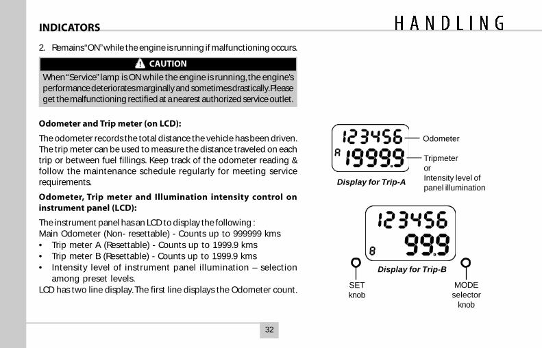
Odometer and Trip meter (on LCD):
The odometer records the total distance the vehicle has been driven.The trip meter can be used to measure the distance traveled on eachtrip or between fuel fillings. Keep track of the odometer reading &follow the maintenance schedule regularly for meeting servicerequirements.
Odometer, Trip meter and Illumination intensity control oninstrument panel (LCD):
The instrument panel has an LCD to display the following :Main Odometer (Non- resettable) - Counts up to 999999 kms• Trip meter A (Resettable) - Counts up to 1999.9 kms• Trip meter B (Resettable) - Counts up to 1999.9 kms• Intensity level of instrument panel illumination – selection
among preset levels.LCD has two line display. The first line displays the Odometer count.
Odometer
TripmeterorIntensity level ofpanel illumination
Display for Trip-A
Display for Trip-B
MODEselector
knob
SETknob
2. Remains “ON” while the engine is running if malfunctioning occurs.
CAUTION
When “Service” lamp is ON while the engine is running, the engine’sperformance deteriorates marginally and sometimes drastically. Pleaseget the malfunctioning rectified at a nearest authorized service outlet.
33
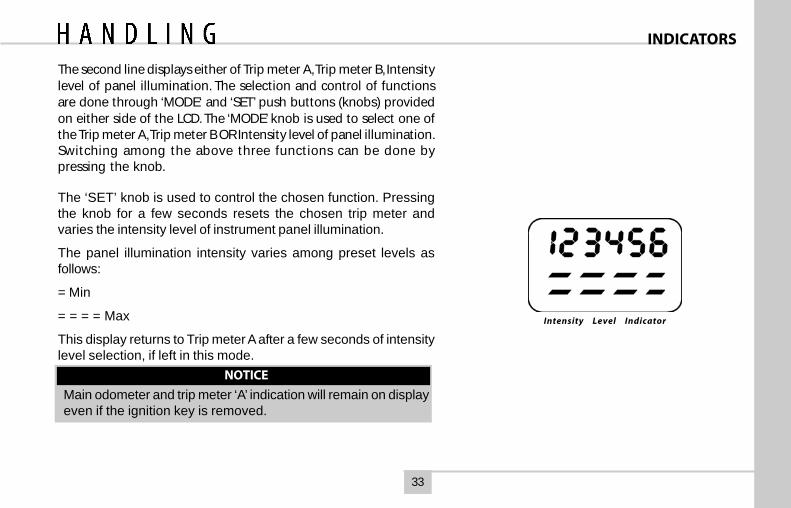
Intensity Level Indicator
The second line displays either of Trip meter A, Trip meter B, Intensitylevel of panel illumination. The selection and control of functionsare done through ‘MODE‘ and ‘SET’ push buttons (knobs) providedon either side of the LCD. The ‘MODE’ knob is used to select one ofthe Trip meter A, Trip meter B OR Intensity level of panel illumination.Switching among the above three functions can be done bypressing the knob.
The ‘SET’ knob is used to control the chosen function. Pressingthe knob for a few seconds resets the chosen trip meter andvaries the intensity level of instrument panel illumination.
The panel illumination intensity varies among preset levels asfollows:
= Min
= = = = Max
This display returns to Trip meter A after a few seconds of intensitylevel selection, if left in this mode.
NOTICE
Main odometer and trip meter ‘A’ indication will remain on displayeven if the ignition key is removed.
INDICATORS

34
RPM meter (if provided) :
The meter indicates engine speed in revolutions perminute (rpm) Change gears at appropriate engine rpmand vehicle speed to get optimum fuel economy. Thepermitted engine rpm upper limit is the start of Red Zoneon the dial.
Fuel Gauge:
The fuel gauge indicates the approximate fuel level in thetank. Refill the fuel tank at the earliest, before the needletouches the red band on the gauge. At this point, fuellevel in tank is low and it is advised to get fuel filledimmediately
Temperature gauge:The gauge indicates the temperature of the enginecoolant. The red zone at ‘H’ indicates temperature higherthan the normal. Avoid driving, when the pointer is in thered zone. It indicates engine overheating, which maybe due to insufficient coolant in the radiator or due toany other defect. At this stage take the car to the nearestAuthorised Service outlet for necessary attention.Caution: Never remove the radiator pressure cap from theradiator when the engine is hot. Do not restart the engineuntil the problem has been duly attended.The speedometer: The speedometer indicates thevehicle speed in km/hr.
GAUGES
Speedometer
Temperature Guage
HighTemperature
Warning
RPM meter
Fuel Guage
Low FuelWarning
Fuel Guage
TempGuage
Low FuelWarning
HighTemperature
Warning
35
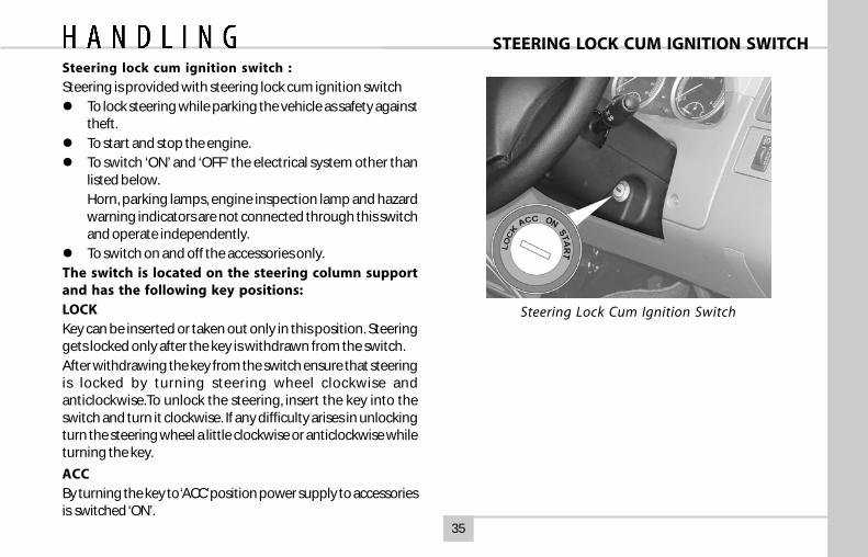
Steering lock cum ignition switch :
Steering is provided with steering lock cum ignition switchTo lock steering while parking the vehicle as safety againsttheft.To start and stop the engine.To switch ‘ON’ and ‘OFF’ the electrical system other thanlisted below.Horn, parking lamps, engine inspection lamp and hazardwarning indicators are not connected through this switchand operate independently.To switch on and off the accessories only.
The switch is located on the steering column supportand has the following key positions:LOCKKey can be inserted or taken out only in this position. Steeringgets locked only after the key is withdrawn from the switch.After withdrawing the key from the switch ensure that steeringis locked by turning steering wheel clockwise andanticlockwise.To unlock the steering, insert the key into theswitch and turn it clockwise. If any difficulty arises in unlockingturn the steering wheel a little clockwise or anticlockwise whileturning the key.
ACCBy turning the key to ‘ACC’ position power supply to accessoriesis switched ‘ON’.
STEERING LOCK CUM IGNITION SWITCH
Steering Lock Cum Ignition Switch
36
STEERING LOCK CUM IGNITION SWITCH
ON
By turning the key to this position all remaining electricalsystems become operative and lamps of battery chargingindicator, low oil pressure will come ‘ON’.
In ‘ON’ position, the glow plug controller switches ‘ON’ theglow plugs and glow indicator lights up. After a fewseconds, depending on the ambient temperature, theindicator light only goes off indicating that the engine canbe started. Glow plugs remain ‘ON’ for few seconds andswitches ‘OFF’ automatically.
As a safety feature glow plugs are automatically switched‘OFF’ after a lapse of certain time if the engine is not startedto conserve battery.
In this case to start the engine repeat the operation byfirst going to ‘ACC’ or ‘LOCK’ position.
START
Turn the key further clockwise to start position (springloaded) to operate starter motor. As soon as the enginestarts release the ignition key, so that key can come backto ‘ON’ position and starter motor disengages and glowplug is switched ‘OFF’. Vehicle is driven in this position. Byturning the ignition key from ‘ON’ position to ‘ACC’ or ‘LOCK’position engine can be stopped.
37
COMBINATION SWITCH & LIGHTS
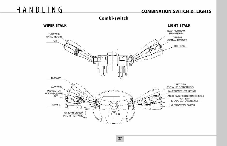
Combi-switch
WIPER STALK LIGHT STALK
FLICK WIPESPRING RETURN
OFF
FLASH HIGH BEAMSPRING RETURN
DIP BEAM(NORMAL POSITION)
HIGH BEAM
FAST WIPE
SLOW WIPE
PUSH SWITCHFOR WASH & WIPE
OFF
INT. WIPE
DELAY TIMING FORINTERMITTENT WIPE
MAX.
MIN.
LEFT TURN(SIGNAL SELF CANCELLING)
LANE CHANGE LEFT (SPRING)
LANE CHANGE RIGHT (SPRING RETURN)RIGHT TURN
(SIGNAL SELF CANCELLING)
LIGHTS CONTROL SWITCH
38
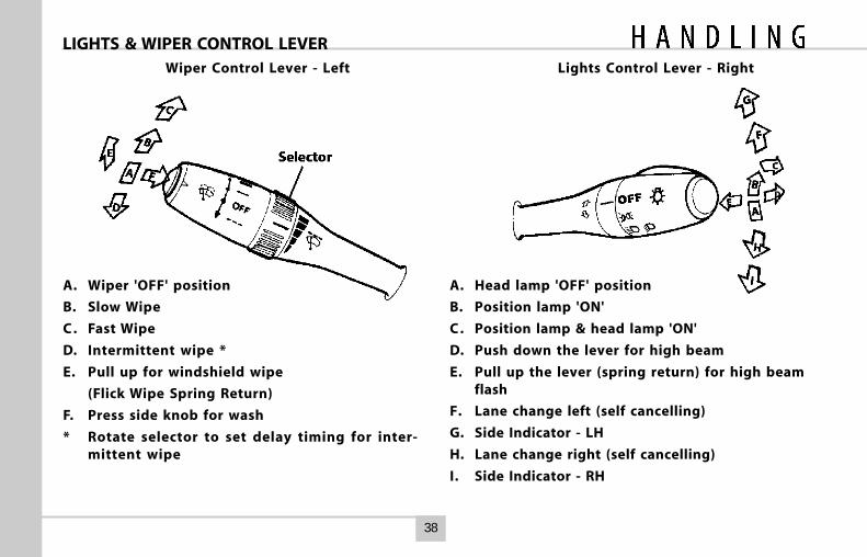
LIGHTS & WIPER CONTROL LEVERWiper Control Lever - Left Lights Control Lever - Right
A. Wiper 'OFF' position
B. Slow Wipe
C . Fast Wipe
D. Intermittent wipe *
E. Pull up for windshield wipe
(Flick Wipe Spring Return)
F. Press side knob for wash
* Rotate selector to set delay timing for inter-mittent wipe
A. Head lamp 'OFF' position
B. Position lamp 'ON'
C . Position lamp & head lamp 'ON'
D. Push down the lever for high beam
E. Pull up the lever (spring return) for high beamflash
F. Lane change left (self cancelling)
G. Side Indicator - LH
H. Lane change right (self cancelling)
I. Side Indicator - RH
39
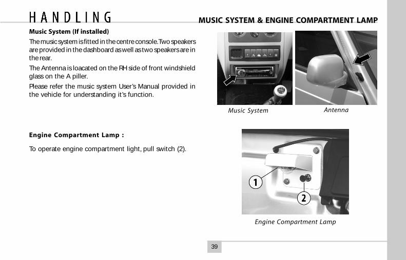
Music System (If installed)
The music system is fitted in the centre console. Two speakersare provided in the dashboard as well as two speakers are inthe rear.
The Antenna is loacated on the RH side of front windshieldglass on the A piller.
Please refer the music system User’s Manual provided inthe vehicle for understanding it’s function.
Engine Compartment Lamp :
To operate engine compartment light, pull switch (2).
Music System
MUSIC SYSTEM & ENGINE COMPARTMENT LAMP
Antenna
Engine Compartment Lamp
40
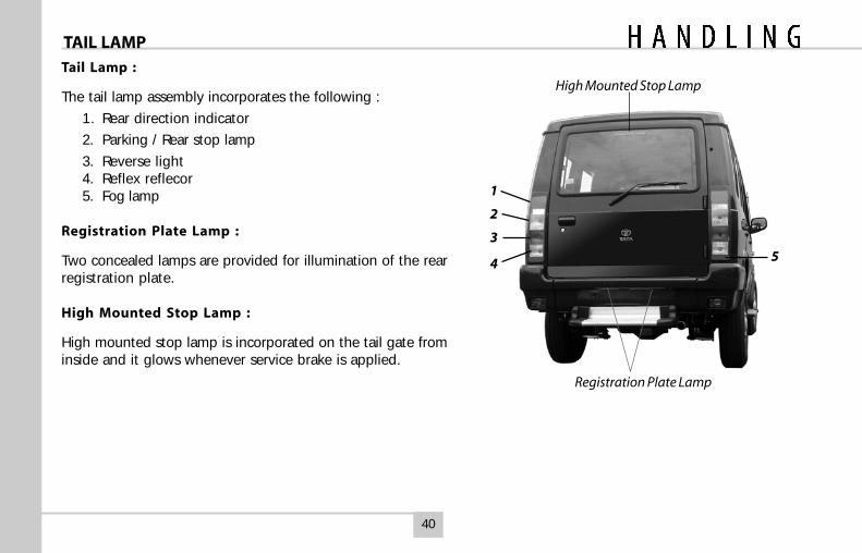
Tail Lamp :
The tail lamp assembly incorporates the following :
1. Rear direction indicator
2. Parking / Rear stop lamp
3. Reverse light4. Reflex reflecor5. Fog lamp
Registration Plate Lamp :
Two concealed lamps are provided for illumination of the rearregistration plate.
High Mounted Stop Lamp :
High mounted stop lamp is incorporated on the tail gate frominside and it glows whenever service brake is applied.
TAIL LAMP
5
High Mounted Stop Lamp
Registration Plate Lamp
1
2
3
4
41
INTERIOR ROOF LAMPS
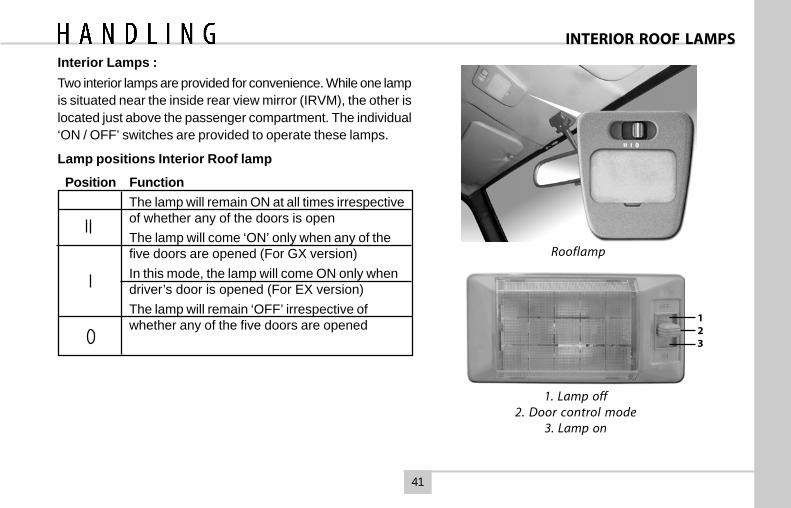
1. Lamp off2. Door control mode
3. Lamp on
Rooflamp
123
Interior Lamps :Two interior lamps are provided for convenience. While one lampis situated near the inside rear view mirror (IRVM), the other islocated just above the passenger compartment. The individual‘ON / OFF’ switches are provided to operate these lamps.
Lamp positions Interior Roof lamp
Position FunctionThe lamp will remain ON at all times irrespectiveof whether any of the doors is openThe lamp will come ‘ON’ only when any of thefive doors are opened (For GX version)In this mode, the lamp will come ON only whendriver’s door is opened (For EX version)The lamp will remain ‘OFF’ irrespective ofwhether any of the five doors are opened
42
HEAD LAMP LEVELING SWITCH
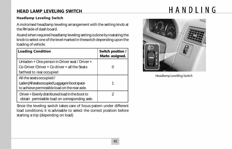
Headlamp Levelling Switch
Headlamp Leveling Switch
A motorised headlamp leveling arrangement with the setting knob atthe RH side of dash board.
As and when required headlamp leveling setting is done by roatating theknob to select one of the level marked in theswitch depending upon theloading of vehicle.
Loading Condition Switch position /Marks assigned.
Unladen + One person in Driver seat / Driver +Co-Driver /Driver + Co driver + all the Seats 0farthest to rear occupied
All the seats occupied /Laden (All seats occupied Luggage in boot space 1to achieve permissible load on the rear axle.
Driver + Evenly distributed load in the boot to 2 obtain permissible load on corresponding axle.
Since the leveling switch takes care of focus patern under differentload conditions; it is advisable to select the correct position beforestarting a trip (depending on load)
43
ACCESSORY SWITCHESACCESSORY SWITCHES
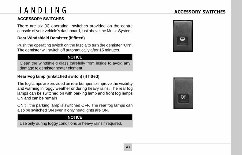
There are six (6) operating switches provided on the centreconsole of your vehicle’s dashboard, just above the Music System.
Rear Windshield Demister (if fitted)
Push the operating switch on the fascia to turn the demister “ON”.The demister will switch off automatically after 15 minutes.
NOTICEClean the windshield glass carefully from inside to avoid anydamage to demister heater element
Rear Fog lamp (unlatched switch) (if fitted)
The fog lamps are provided on rear bumper to improve the visibilityand warning in foggy weather or during heavy rains. The rear foglamps can be switched on with parking lamp and front fog lampsON and can be remain
ON till the parking lamp is switched OFF. The rear fog lamps canalso be switched ON even if only headlights are ON.
NOTICEUse only during foggy conditions or heavy rains if required.
44
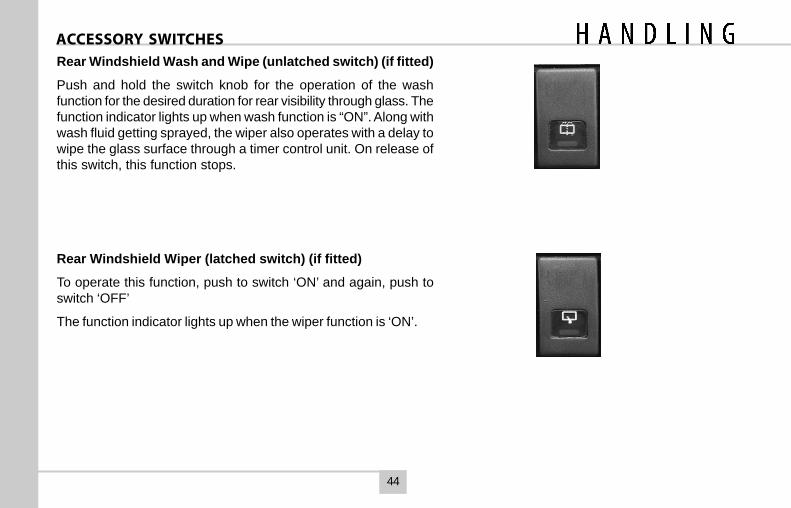
ACCESSORY SWITCHESRear Windshield Wash and Wipe (unlatched switch) (if fitted)
Push and hold the switch knob for the operation of the washfunction for the desired duration for rear visibility through glass. Thefunction indicator lights up when wash function is “ON”. Along withwash fluid getting sprayed, the wiper also operates with a delay towipe the glass surface through a timer control unit. On release ofthis switch, this function stops.
Rear Windshield Wiper (latched switch) (if fitted)
To operate this function, push to switch ‘ON’ and again, push toswitch ‘OFF’
The function indicator lights up when the wiper function is ‘ON’.
45
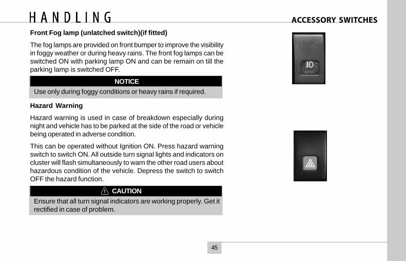
Front Fog lamp (unlatched switch)(if fitted)
The fog lamps are provided on front bumper to improve the visibilityin foggy weather or during heavy rains. The front fog lamps can beswitched ON with parking lamp ON and can be remain on till theparking lamp is switched OFF.
NOTICEUse only during foggy conditions or heavy rains if required.
Hazard Warning
Hazard warning is used in case of breakdown especially duringnight and vehicle has to be parked at the side of the road or vehiclebeing operated in adverse condition.
This can be operated without Ignition ON. Press hazard warningswitch to switch ON. All outside turn signal lights and indicators oncluster will flash simultaneously to warn the other road users abouthazardous condition of the vehicle. Depress the switch to switchOFF the hazard function.
CAUTIONEnsure that all turn signal indicators are working properly. Get itrectified in case of problem.
ACCESSORY SWITCHES
46
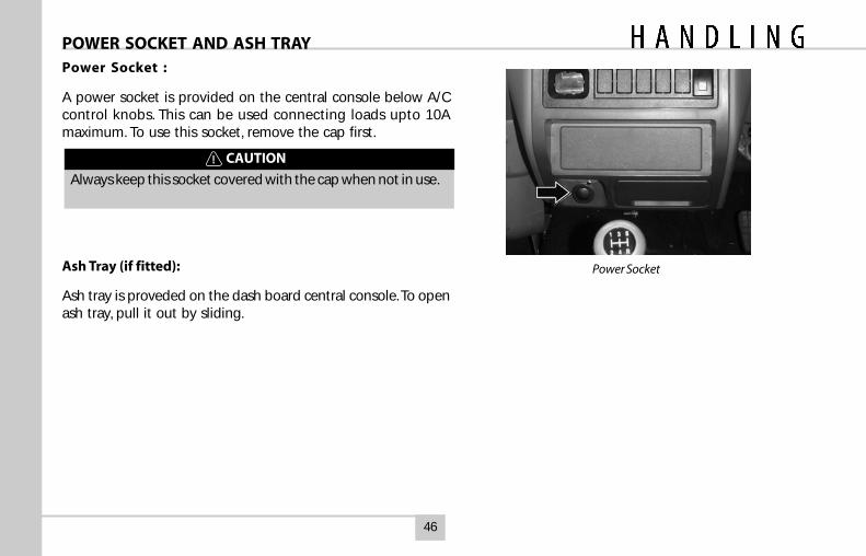
Power Socket
POWER SOCKET AND ASH TRAYPower Socket :
A power socket is provided on the central console below A/Ccontrol knobs. This can be used connecting loads upto 10Amaximum. To use this socket, remove the cap first.
CAUTION
Always keep this socket covered with the cap when not in use.
Ash Tray (if fitted):
Ash tray is proveded on the dash board central console. To openash tray, pull it out by sliding.
47
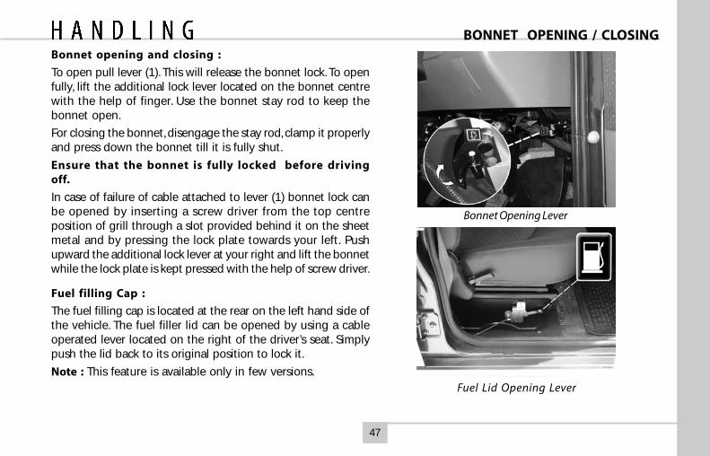
Bonnet opening and closing :
To open pull lever (1). This will release the bonnet lock. To openfully, lift the additional lock lever located on the bonnet centrewith the help of finger. Use the bonnet stay rod to keep thebonnet open.
For closing the bonnet, disengage the stay rod, clamp it properlyand press down the bonnet till it is fully shut.
Ensure that the bonnet is fully locked before drivingoff.
In case of failure of cable attached to lever (1) bonnet lock canbe opened by inserting a screw driver from the top centreposition of grill through a slot provided behind it on the sheetmetal and by pressing the lock plate towards your left. Pushupward the additional lock lever at your right and lift the bonnetwhile the lock plate is kept pressed with the help of screw driver.
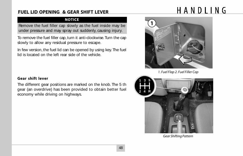
Fuel filling Cap :
The fuel filling cap is located at the rear on the left hand side ofthe vehicle. The fuel filler lid can be opened by using a cableoperated lever located on the right of the driver’s seat. Simplypush the lid back to its original position to lock it.
Note : This feature is available only in few versions.
BONNET OPENING / CLOSING
Bonnet Opening Lever
Fuel Lid Opening Lever
48
1. Fuel Flap 2. Fuel Filler Cap
Gear Shifting Pattern
FUEL LID OPENING & GEAR SHIFT LEVER
1NOTICE
Remove the fuel filler cap slowly as the fuel inside may beunder pressure and may spray out suddenly, causing injury.
To remove the fuel filler cap, turn it anti-clockwise. Turn the capslowly to allow any residual pressure to escape.
In few version, the fuel lid can be opened by using key. The fuellid is located on the left rear side of the vehicle.
Gear shift lever
The different gear positions are marked on the knob. The 5 thgear (an overdrive) has been provided to obtain better fueleconomy while driving on highways.
1 3 5
2 4 R
49
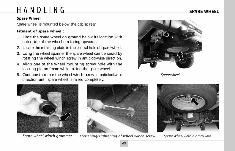
Spare Wheel
Spare wheel is mounted below the cab at rear.
Fitment of spare wheel :
1. Place the spare wheel on ground below its location withouter side of the wheel rim facing upwards.
2. Locate the retaining plate in the central hole of spare wheel.
3. Using the wheel spanner the spare wheel can be raised byrotating the wheel winch screw in anticlockwise direction.
4. Align one of the wheel mounting screw hole with thelocating pin on frame while raising the spare wheel.
5. Continue to rotate the wheel winch screw in anticlockwisedirection until spare wheel is raised completely.
Spare wheel
Spare wheel winch grommet Loosening/Tightening of wheel winch screw Spare Wheel Retaininmg Plate
SPARE WHEEL
50
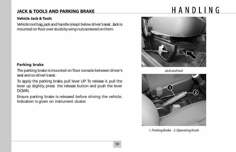
Vehicle Jack & Tools
Vehicle tool bag, jack and handle is kept below driver’s seat. Jack ismounted on floor over studs by wing nuts screwed on them.
Parking brake
The parking brake is mounted on floor console between driver’sseat and co-driver’s seat.
To apply the parking brake, pull lever UP. To release it, pull thelever up slightly, press the release button and push the leverDOWN.
Ensure parking brake is released before driving the vehicle.Indication is given on instrument cluster.
Jack and tool
1. Parking Brake 2. Operating Knob
JACK & TOOLS AND PARKING BRAKE
12
51
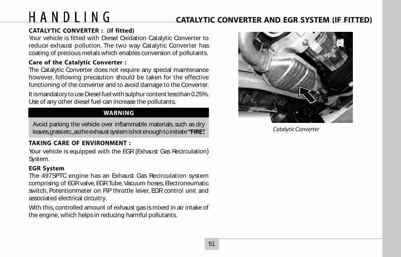
CATALYTIC CONVERTER AND EGR SYSTEM (IF FITTED)CATALYTIC CONVERTER : (if fitted)Your vehicle is fitted with Diesel Oxidation Catalytic Converter toreduce exhaust pollution. The two way Catalytic Converter hascoating of precious metals which enables conversion of pollutants.
Care of the Catalytic Converter :The Catalytic Converter does not require any special maintenancehowever, following precaution should be taken for the effectivefunctioning of the converter and to avoid damage to the Converter.
It is mandatory to use Diesel fuel with sulphur content less than 0.25%.Use of any other diesel fuel can increase the pollutants.
WARNING
Avoid parking the vehicle over inflammable materials, such as dryleaves, grass etc., as the exhaust system is hot enough to initiate “FIRE”.
TAKING CARE OF ENVIRONMENT :Your vehicle is equipped with the EGR (Exhaust Gas Recirculation)System.
EGR SystemThe 497SPTC engine has an Exhaust Gas Recirculation systemcomprising of EGR valve, EGR Tube, Vacuum hoses, Electroneumaticswitch, Potentionmeter on FIP throttle lever, EGR control unit andassociated electrical circuitry.
With this, controlled amount of exhaust gas is mixed in air intake ofthe engine, which helps in reducing harmful pollutants.
Catalytic Converter
52
Turbocharger
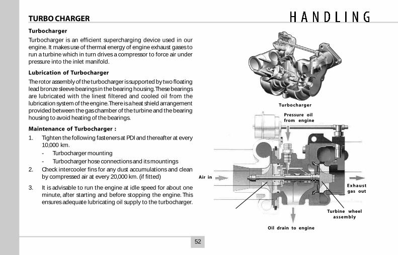
Turbocharger is an efficient supercharging device used in ourengine. It makes use of thermal energy of engine exhaust gases torun a turbine which in turn drives a compressor to force air underpressure into the inlet manifold.
Lubrication of Turbocharger
The rotor assembly of the turbocharger is supported by two floatinglead bronze sleeve bearings in the bearing housing. These bearingsare lubricated with the linest filtered and cooled oil from thelubrication system of the engine. There is a heat shield arrangementprovided between the gas chamber of the turbine and the bearinghousing to avoid heating of the bearings.
Maintenance of Turbocharger :
1. Tighten the following fasteners at PDI and thereafter at every10,000 km.
- Turbocharger mounting
- Turbocharger hose connections and its mountings2. Check intercooler fins for any dust accumulations and clean
by compressed air at every 20,000 km. (if fitted)
3. It is advisable to run the engine at idle speed for about oneminute, after starting and before stopping the engine. Thisensures adequate lubricating oil supply to the turbocharger.
Turbocharger
TURBO CHARGER
Oil drain to engine
Pressure oilfrom engine
Exhaustgas out
Air in
Turbine wheelassembly
53
POWER STEERING (When provided)Power steering is fitted for lighter steering effort and easymanoeuvrability. The system consists of steering gear box,hydraulic pump and hydraulic reservoir suitably mounted andconnected by piping. Pump drive is through belt from engine.Power assistance is available during normal functioning of thepower steering system.
In case of any failure in hydraulic system, the steeringcan be operated mechanically with increased steeringeffort for bringing the vehicle to a repair station.
Procedure for oil filling and bleeding the power steeringsystem. ( Ensure that the reservoir is totally cleaned beforestarting the work. )
1. Fill the reservoir nearly full. Crank the engine for 10 secondswithout, if possible, allowing it to start. If the engine doesstart, shut off immediately. Check and refill the reservoir.Repeat atleast three times, each time checking and refillingthe reservoir.
2. Check for any leakage in the system and if noticed takecorrective action.
3. Start the engine and steer the vehicle from full left to fullright turn 3-4 times. Add fluid if necessary to maintain thelevel up to the filter top.
4. With the engine at steady speed check for bubble /foamingin the fluid. If present it indicates that air is getting suckedinto the system.
POWER STEERINGCheck the suction line / fittings and correct if necessary.
5. Once the system is bled properly and free from foaming,there should not be appreciable change in fluid level inthe reservoir, when the engine is started / stop repeatedly.Top up or remove excess fluid so that the final level is at ‘H’mark on dipstick.
6. Now the system is ready for driving.
CAUTION
Do not allow the fluid level to drop significantly or run outof the reservoir during the above operation. This may induceair into the system.
Do not start the engine without fluid in the power steeringsystem. This will result in serious damage to the pump.
NOTICE
Always use recommended brand of fluid from closedcontainers. Any dirty fluid poured in the system will result indamage to pump/gear.
54
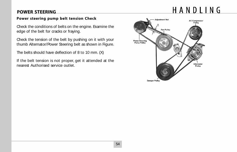
Power steering pump belt tension Check
Check the conditions of belts on the engine. Examine theedge of the belt for cracks or fraying.
Check the tension of the belt by pushing on it with yourthumb Alternator/Power Steering belt as shown in Figure.
The belts should have deflection of 8 to 10 mm. (X)
If the belt tension is not proper, get it attended at thenearest Authorised service outlet.
POWER STEERING
55
AIR CONDITIONING
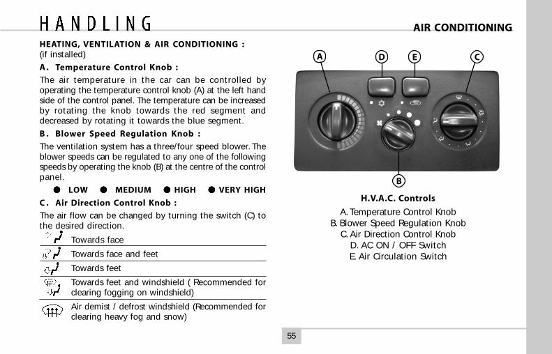
HEATING, VENTILATION & AIR CONDITIONING :(if installed)
A . Temperature Control Knob :
The air temperature in the car can be controlled byoperating the temperature control knob (A) at the left handside of the control panel. The temperature can be increasedby rotating the knob towards the red segment anddecreased by rotating it towards the blue segment.
B . Blower Speed Regulation Knob :
The ventilation system has a three/four speed blower. Theblower speeds can be regulated to any one of the followingspeeds by operating the knob (B) at the centre of the controlpanel.
● ● ● ● ● LOW ● ● ● ● ● MEDIUM ●●●●● HIGH ●●●●● VERY HIGH
C . Air Direction Control Knob :
The air flow can be changed by turning the switch (C) tothe desired direction.
Towards face
Towards face and feet
Towards feet
Towards feet and windshield ( Recommended forclearing fogging on windshield)
Air demist / defrost windshield (Recommended forclearing heavy fog and snow)
H.V.A.C. Controls
A. Temperature Control KnobB. Blower Speed Regulation Knob
C. Air Direction Control KnobD. AC ON / OFF SwitchE. Air Circulation Switch
A
B
CD E
56
AIR CONDITIONING
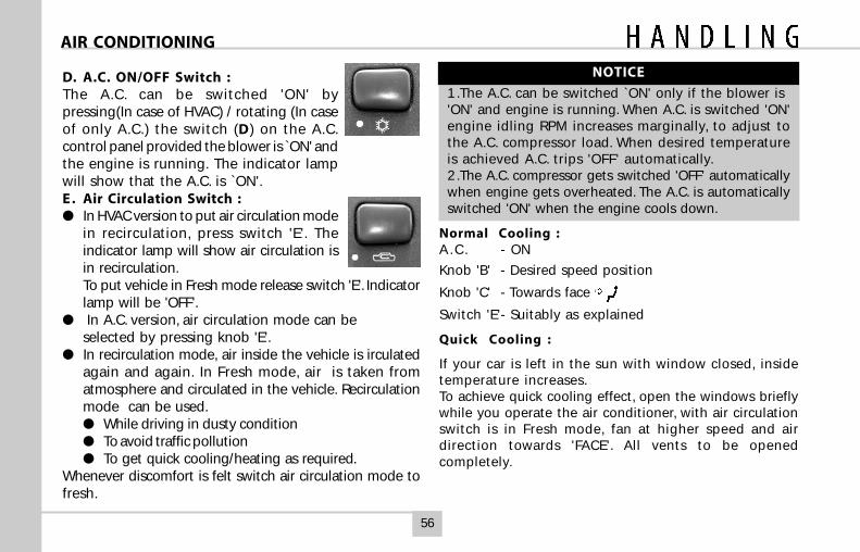
D. A.C. ON/OFF Switch :The A.C. can be switched 'ON' bypressing(In case of HVAC) / rotating (In caseof only A.C.) the switch (D) on the A.C.control panel provided the blower is ̀ ON' andthe engine is running. The indicator lampwill show that the A.C. is `ON'.E . Air Circulation Switch :● In HVAC version to put air circulation mode
in recirculation, press switch 'E'. Theindicator lamp will show air circulation isin recirculation.To put vehicle in Fresh mode release switch 'E'. Indicatorlamp will be 'OFF'.
● In A.C. version, air circulation mode can beselected by pressing knob 'E'.
● In recirculation mode, air inside the vehicle is irculatedagain and again. In Fresh mode, air is taken fromatmosphere and circulated in the vehicle. Recirculationmode can be used.● While driving in dusty condition● To avoid traffic pollution● To get quick cooling/heating as required.
Whenever discomfort is felt switch air circulation mode tofresh.
NOTICE
1 .The A.C. can be switched `ON' only if the blower is'ON' and engine is running. When A.C. is switched 'ON'engine idling RPM increases marginally, to adjust tothe A.C. compressor load. When desired temperatureis achieved A.C. trips 'OFF' automatically.2 .The A.C. compressor gets switched 'OFF' automaticallywhen engine gets overheated. The A.C. is automaticallyswitched 'ON' when the engine cools down.
Normal Cooling :A . C . - ON
Knob 'B' - Desired speed position
Knob 'C' - Towards face
Switch 'E'- Suitably as explained
Quick Cooling :
If your car is left in the sun with window closed, insidetemperature increases.To achieve quick cooling effect, open the windows brieflywhile you operate the air conditioner, with air circulationswitch is in Fresh mode, fan at higher speed and airdirection towards 'FACE'. All vents to be openedcompletely.
57
AIR CONDITIONING
Once temperature inside has come down sufficiently, closethe windows and change air circulation suitably to fresh/recirculation.
Demisting :
In rainy season or in areas of high humidity, mist formationinside windshield glass is observed. To clear mist dehumidifiedair is passed on the windshield glass.
The position of control knobs should be adjusted as follows :
A.C. - ON
Knob 'B' - Desired speed position
Knob 'C' - Towards windshield
Knob 'A' (for vehicles fitted with HVAC) - at suitable temperature
Air circulation - at suitable position
NOTICE
When mist gets cleared switch the knob "C' position to Facemode. In high humidity areas, if cold air continues to flowover windshield, it may cause sudden fogging on outsidesurface of windshield.
Defrosting : (For vehicles fitted with HVAC unit)
In low temperature areas, to clear frost formation outsidethe windshield glass, this setting is used.
First start the engine and accelerate to warm up.Knob'A' - Maximum hot position
Knob 'B' - Very High
Knob 'C' - Towards windshield
Switch 'E' - Fresh air mode condition
Once the windscreen has become clear, move the fanswitch to desired speed.
NOTICE
Electric heater coil is provided for demisting of tail gateglass for deluxe versions.
Normal Heating : ( For vehicles fitted with HVAC )
Knob 'A' - Suitable temperature position
Knob 'B' - Suitable blower speed
Knob 'C' - Towards face & feet
A . C . - OFF
Air Circulation- Fresh switch
58
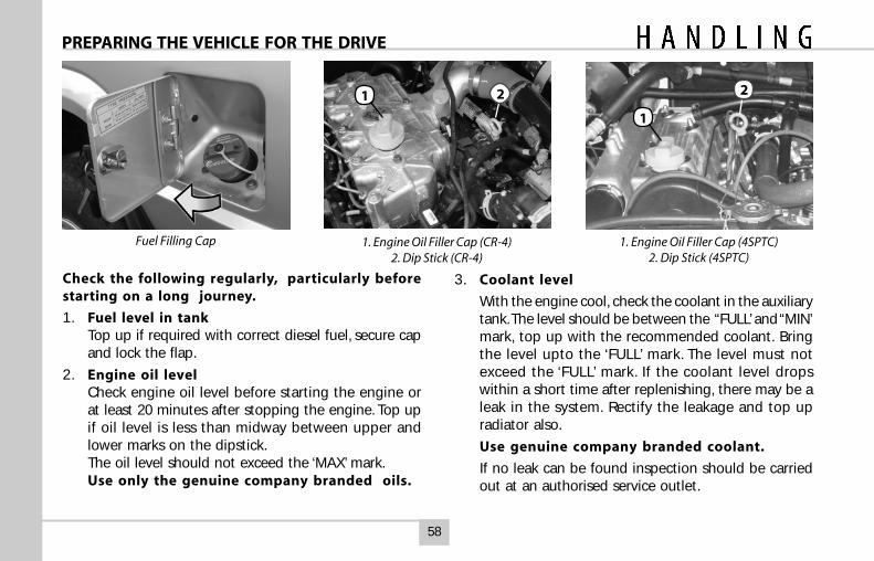
Check the following regularly, particularly beforestarting on a long journey.
1. Fuel level in tankTop up if required with correct diesel fuel, secure capand lock the flap.
2. Engine oil levelCheck engine oil level before starting the engine orat least 20 minutes after stopping the engine. Top upif oil level is less than midway between upper andlower marks on the dipstick.The oil level should not exceed the ‘MAX’ mark.Use only the genuine company branded oils.
3. Coolant level
With the engine cool, check the coolant in the auxiliarytank. The level should be between the “FULL’ and “MIN’mark, top up with the recommended coolant. Bringthe level upto the ‘FULL’ mark. The level must notexceed the ‘FULL’ mark. If the coolant level dropswithin a short time after replenishing, there may be aleak in the system. Rectify the leakage and top upradiator also.
Use genuine company branded coolant.
If no leak can be found inspection should be carriedout at an authorised service outlet.
PREPARING THE VEHICLE FOR THE DRIVE
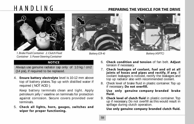
Fuel Filling Cap 1. Engine Oil Filler Cap (CR-4)2. Dip Stick (CR-4)
1 2
1. Engine Oil Filler Cap (4SPTC)2. Dip Stick (4SPTC)
1
2
59
Battery (CR-4)
NOTICE
Always use genuine radiator cap only of 1.0 kg / cm2(14 psi), if required to be replaced.
4. Ensure battery electrolyte level is 10-12 mm abovetop of battery plates. Top up with distilled water ifrequired ( NOT ACID ).
Keep battery terminals clean and tight. Applypetroleum jelly / vaseline on terminals for protectionagainst corrosion. Secure covers provided overterminals.
5. Check all lights, horn, gauges, switches andwiper for proper functioning.
6. Check condition and tension of fan belt. Adjusttension if necessary.
7. Check leakages of coolant, fuel and oil at alljoints of hoses and pipes and rectify, if any. Ifcoolant leakages is noticed, rectify the leakages andtop up radiator also with recommended coolant.
8. Check level of brake fluid in plastic container. Top upif necessary. Do not overfill.Use only genuine company branded brakefluid.
9. Check level of clutch fluid in plastic container. Topup if necessary. Do not overfill as this would result inspillage during clutch operation.Use only genuine company branded clutch fluid.
PREPARING THE VEHICLE FOR THE DRIVE
Battery (4SPTC)1. Brake Fluid Container 2. Clutch FluidContainer 3. Power Steering Container
1 2
3
60
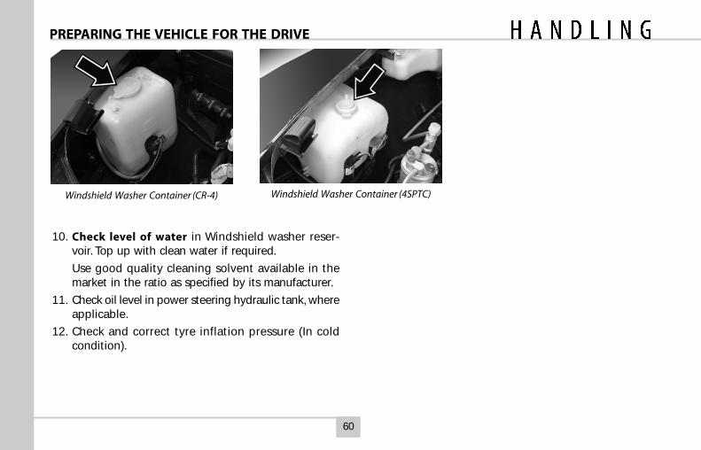
10. Check level of water in Windshield washer reser-voir. Top up with clean water if required.
Use good quality cleaning solvent available in themarket in the ratio as specified by its manufacturer.
11. Check oil level in power steering hydraulic tank, whereapplicable.
12. Check and correct tyre inflation pressure (In coldcondition).
PREPARING THE VEHICLE FOR THE DRIVE
Windshield Washer Container (CR-4) Windshield Washer Container (4SPTC)
61
Start the engine and observe that :
Low oil pressure indicator light goes ‘OFF’
Battery charging indicator light goes ‘OFF’
ENSURE THAT PARKING BRAKE ISRELEASED (INDICATOR LAMP ‘OFF’)
VEHICLE IS NOW READY FOR A DRIVE.
DO NOT ALLOW VEHICLE TO ROLLBACK ON GRADIENTS.
BEFORE DRIVING
Check
Fuel level
Coolant level
Engine oil level
Tyre pressure
Brake and clutch fluid level
Doors are firmly closed
Adjust
Driver seat
Rear view mirrors
Ensure
Gear shift lever is in neutralposition.
All switches and lamps areworking.
Brake fail indicator is ‘OFF’
Fuel level indicated on fuel gaugeis above reserve tank.
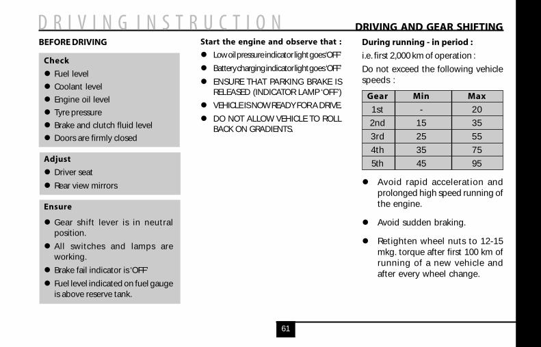
DRIVING AND GEAR SHIFTINGDuring running - in period :
i.e. first 2,000 km of operation :
Do not exceed the following vehiclespeeds :
Gear Min Max
1st - 20
2nd 15 35
3rd 25 55
4th 35 75
5th 45 95
Avoid rapid acceleration andprolonged high speed running ofthe engine.
Avoid sudden braking.
Retighten wheel nuts to 12-15mkg. torque after first 100 km ofrunning of a new vehicle andafter every wheel change.
62
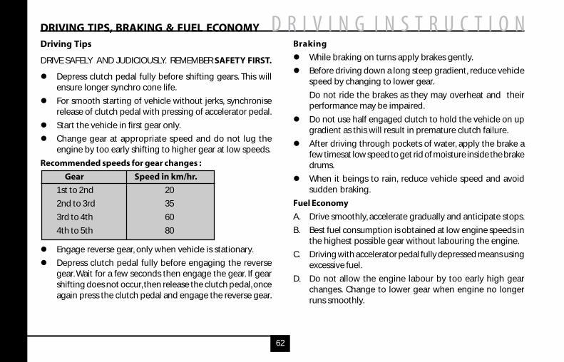
DRIVING TIPS, BRAKING & FUEL ECONOMYDriving Tips
DRIVE SAFELY AND JUDICIOUSLY. REMEMBER SAFETY FIRST.
Depress clutch pedal fully before shifting gears. This willensure longer synchro cone life.
For smooth starting of vehicle without jerks, synchroniserelease of clutch pedal with pressing of accelerator pedal.
Start the vehicle in first gear only.
Change gear at appropriate speed and do not lug theengine by too early shifting to higher gear at low speeds.
Recommended speeds for gear changes :
Gear Speed in km/hr.
1st to 2nd 20
2nd to 3rd 35
3rd to 4th 60
4th to 5th 80
Engage reverse gear, only when vehicle is stationary.
Depress clutch pedal fully before engaging the reversegear. Wait for a few seconds then engage the gear. If gearshifting does not occur, then release the clutch pedal, onceagain press the clutch pedal and engage the reverse gear.
Braking
While braking on turns apply brakes gently.
Before driving down a long steep gradient, reduce vehiclespeed by changing to lower gear.
Do not ride the brakes as they may overheat and theirperformance may be impaired.
Do not use half engaged clutch to hold the vehicle on upgradient as this will result in premature clutch failure.
After driving through pockets of water, apply the brake afew timesat low speed to get rid of moisture inside the brakedrums.
When it beings to rain, reduce vehicle speed and avoidsudden braking.
Fuel Economy
A. Drive smoothly, accelerate gradually and anticipate stops.
B. Best fuel consumption is obtained at low engine speeds inthe highest possible gear without labouring the engine.
C. Driving with accelerator pedal fully depressed means usingexcessive fuel.
D. Do not allow the engine labour by too early high gearchanges. Change to lower gear when engine no longerruns smoothly.
63
E. If possible, do not idle the engine for more than 5minutes. Switch off the engine.
F. Do not ride the clutch. Do not use clutch pedal as footrest.
G. Depending on traffic conditions, a constant speedshould be maintained.
The vehicle uses more fuel, every time you speed upor slow down.
H. Hard braking, abrupt cornering and rapid accelerationuse more fuel. Avoid these.
Driving on Snowy or Icy Roads
Select the lower gear. Gently release the clutch and applythe accelerator for a smooth start and to avoid wheel spin.
CAUTION
Use of snow tyres and / or tyre chain is recommended.
Maintain a safe distance between vehicles to avoid suddenbraking and slow down by shifting down the gears.
Avoid sudden acceleration, braking or turning. Such sharpmanoeuvres can cause loss of traction and thereby loss ofvehicle control.
Driving on Sandy or Muddy Roads
The extent of muddy / sandy, conditions and the tractionavailable is difficult to judge and the vehicle can getbogged down deeply. Operation should be done at slowspeed only. If possible, get down and check the pathconditions before proceeding.
In case the traction on the wheels is sufficient, you may beable to proceed, it is better to select the lower gear andproceed in the normal manner. To match your power andspeed requirements, you can shift up in any of the 5forward gears or the reverse gear.
NOTICE
You may choose to reduce the tyre pressure marginallyfor additional grip on loose surfaces, though with a slightloss of ground clearance.
Try to maintain a constant engine speed and avoidsudden acceleration which can cause wheel spin andloss of traction, possibly leading to bogging down ofthe vehicle.
If the vehicle gets stuck in loose sand, do not keep onaccelerating as the wheel spin will only result in thewheels sinking deeper.
DRIVING IN ADVERSE CONDITION
64
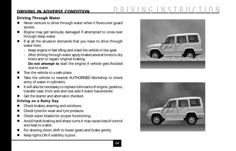
Driving Through WaterNever venture to drive through water when it flows over guardstones.Engine may get seriously damaged if attempted to cross overthrough deep water.If at all the situation demands that you have to drive throughwater then;- Keep engine in fast idling and crawl the vehicle in low gear.- After driving through water apply brakes several times to dry
liners and to regain original braking.Do not attempt to start the engine if vehicle gets floodeddue to water.
Tow the vehicle to a safe place.
Take the vehicle to nearest AUTHORISED Workshop to checkentry of water in cylinders.It will also be necessary to replace lubricants of engine, gearbox,transfer case, front axle and rear axle if water has entered.Get the starter and alternator checked.
Driving on a Rainy DayCheck brakes, steering and windows.Check tyres for wear and tyre pressure.
Check wiper blades for proper functioning.
Avoid harsh braking and sharp turns. It may cause loss of controland lead to a skid.For slowing down, shift to lower gears and brake gently.
Keep lights ON if visibility is poor.
DRIVING IN ADVERSE CONDITION
65
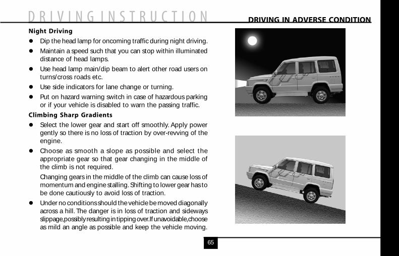
Night Driving
Dip the head lamp for oncoming traffic during night driving.
Maintain a speed such that you can stop within illuminateddistance of head lamps.
Use head lamp main/dip beam to alert other road users onturns/cross roads etc.
Use side indicators for lane change or turning.
Put on hazard warning switch in case of hazardous parkingor if your vehicle is disabled to warn the passing traffic.
Climbing Sharp Gradients
Select the lower gear and start off smoothly. Apply powergently so there is no loss of traction by over-revving of theengine.
Choose as smooth a slope as possible and select theappropriate gear so that gear changing in the middle ofthe climb is not required.
Changing gears in the middle of the climb can cause loss ofmomentum and engine stalling. Shifting to lower gear has tobe done cautiously to avoid loss of traction.
Under no conditions should the vehicle be moved diagonallyacross a hill. The danger is in loss of traction and sidewaysslippage, possibly resulting in tipping over. If unavoidable, chooseas mild an angle as possible and keep the vehicle moving.
DRIVING IN ADVERSE CONDITION
66
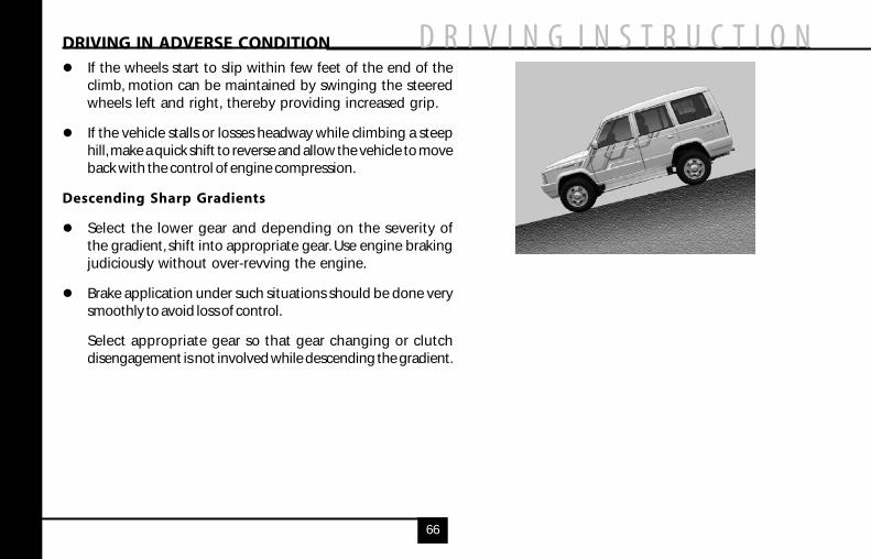
If the wheels start to slip within few feet of the end of theclimb, motion can be maintained by swinging the steeredwheels left and right, thereby providing increased grip.
If the vehicle stalls or losses headway while climbing a steephill, make a quick shift to reverse and allow the vehicle to moveback with the control of engine compression.
Descending Sharp Gradients
Select the lower gear and depending on the severity ofthe gradient, shift into appropriate gear. Use engine brakingjudiciously without over-revving the engine.
Brake application under such situations should be done verysmoothly to avoid loss of control.
Select appropriate gear so that gear changing or clutchdisengagement is not involved while descending the gradient.
DRIVING IN ADVERSE CONDITION
67
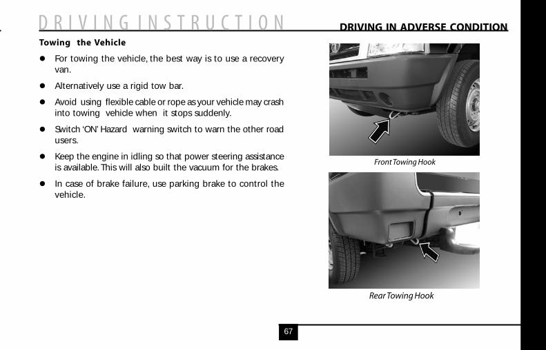
Towing the Vehicle
For towing the vehicle, the best way is to use a recoveryvan.
Alternatively use a rigid tow bar.
Avoid using flexible cable or rope as your vehicle may crashinto towing vehicle when it stops suddenly.
Switch ‘ON’ Hazard warning switch to warn the other roadusers.
Keep the engine in idling so that power steering assistanceis available. This will also built the vacuum for the brakes.
In case of brake failure, use parking brake to control thevehicle.
Front Towing Hook
Rear Towing Hook
DRIVING IN ADVERSE CONDITION
68
DRIVING SAFETY
Seat-Belt
Seat-belts are life saving equipment, useof seat-belt reduces the chance of injuryand severity of injury in case of anaccident. It is strongly recommendedthat all the car occupants should alwayswear seat-belt, while car is in motion.
Influence of Alcohol
Avoid driving under the influence ofalcohol or other drugs. Alcohol anddrugs will severely impair your controlof the vehicle and increase the risk ofinjury to yourself and others.
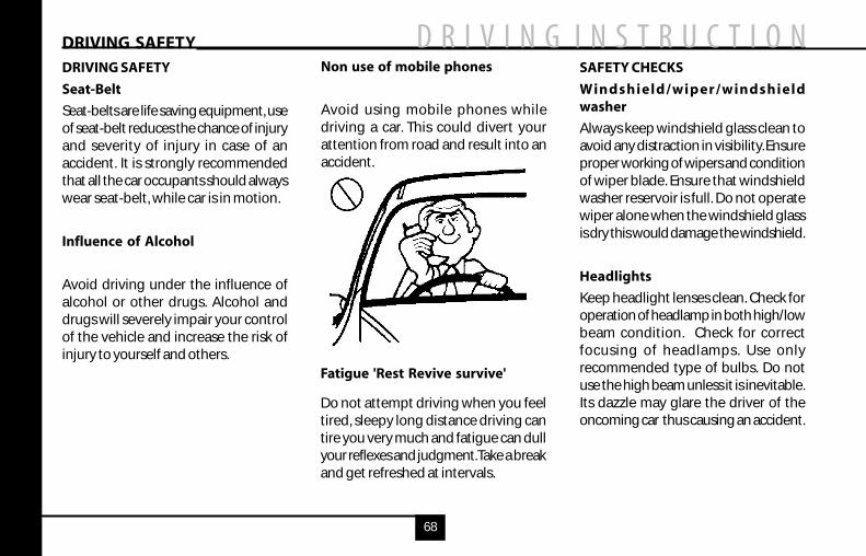
Non use of mobile phones
Avoid using mobile phones whiledriving a car. This could divert yourattention from road and result into anaccident.
Fatigue 'Rest Revive survive'
Do not attempt driving when you feeltired, sleepy long distance driving cantire you very much and fatigue can dullyour reflexes and judgment. Take a breakand get refreshed at intervals.
SAFETY CHECKS
Windshield/wiper/windshieldwasher
Always keep windshield glass clean toavoid any distraction in visibility. Ensureproper working of wipers and conditionof wiper blade. Ensure that windshieldwasher reservoir is full. Do not operatewiper alone when the windshield glassis dry this would damage the windshield.
Headlights
Keep headlight lenses clean. Check foroperation of headlamp in both high/lowbeam condition. Check for correctfocusing of headlamps. Use onlyrecommended type of bulbs. Do notuse the high beam unless it is inevitable.Its dazzle may glare the driver of theoncoming car thus causing an accident.
DRIVING SAFETY
69
Side indicators / Hazard warning
Ensure that all side indicators/hazardwarning lights are always in workingcondition and they are used whenrequired.
Horn
Ensure proper blowing of horn. Hornprovides safety to other road users byalerting your presence.
Brakes
Ensure proper working of brakes. Checkbrake fluid level in reservoir. Do not drivethe car when brake warning lamp is'ON'.
Tyres
Check the condition of tyres for anyabnormalities. Maintain correct tyrepressure, it is very important particularlywhen subjected to extreme condition,such as high speed, high load and highoutside temperature. Do not use wornor bald tyres on the front wheels.
First Aid Kit
First aid kit is provided in your vehicle.This is for use in case of minor injuries. Itis to be regularly checked for anydisintegration and should be updatedwith the new pure contents.
Advance Warning Triangle
There is an advance warning triangleprovided along with your vehicle. Incase there is a breakdown and thevehicle is parked at the side of road, thenthe triangle is to be kept as perinstructions given below :
Remove advance warning trianglefrom case and assemble.
Place the triangle on the road behindthe vehicle when it stranded on theroad. The triangle must be at least 50meters behind the vehicle in thesame lane of traffic.
Increase the distance to 150 meterson a highway or if a bad/hill topobscures the view.
DRIVING SAFETY
70
ENGINE COMPARTMENT
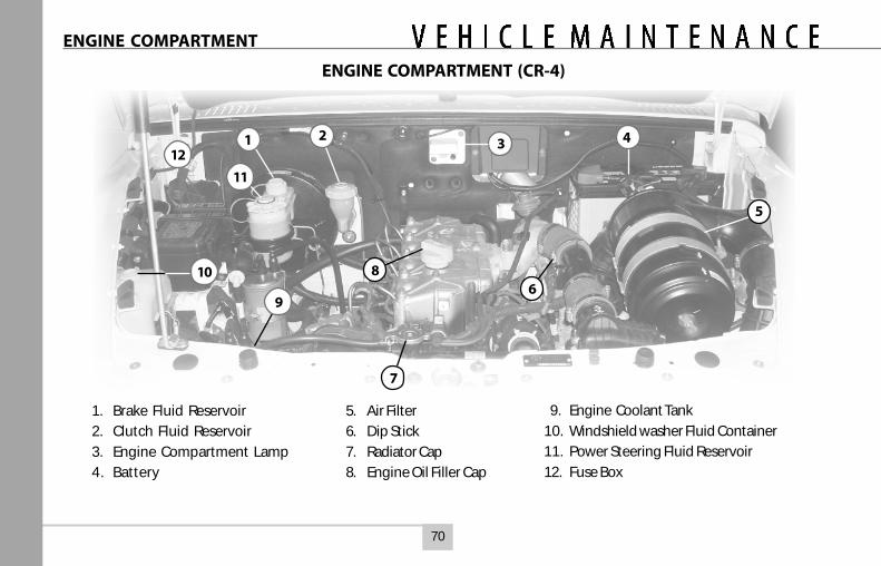
1. Brake Fluid Reservoir
2. Clutch Fluid Reservoir
3. Engine Compartment Lamp
4. Battery
5. Air Filter
6. Dip Stick
7. Radiator Cap
8. Engine Oil Filler Cap
9. Engine Coolant Tank
10. Windshield washer Fluid Container
11. Power Steering Fluid Reservoir
12. Fuse Box
ENGINE COMPARTMENT (CR-4)
31 2 412
5
86
7
9
10
11
71
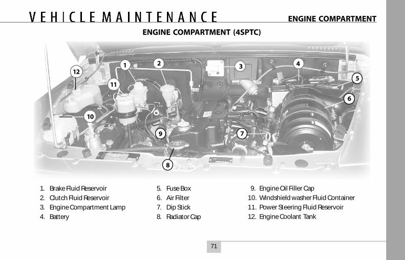
1. Brake Fluid Reservoir
2. Clutch Fluid Reservoir
3. Engine Compartment Lamp
4. Battery
5. Fuse Box
6. Air Filter
7. Dip Stick
8. Radiator Cap
9. Engine Oil Filler Cap
10. Windshield washer Fluid Container
11. Power Steering Fluid Reservoir
12. Engine Coolant Tank
ENGINE COMPARTMENT (4SPTC)
31 2 412
6
7
8
10
11
9
5
ENGINE COMPARTMENT
72
Changing engine oil
Change engine oil in the crankcase at recommended interval.Engine oil should be drained while it is hot. Unscrew enginesump drain plug and allow oil to drain out fully.
Changing oil filter
Unscrew and remove engine oil filter with the help of specialtool, if necessary. Engine oil filter is a spin-on type and cannotbe re-used. Change engine oil filter with every oil change.
Always use genuine engine oil filter for replacement
Destroy the oil filter to avoid resale of the same by unscrupulouspeople. Fill the new oil filter with fresh engine oil. Smear alittle engine oil on rubber gasket of new engine oil filter. Handtighten the filter fully and tighten it a further half turn with aspecial tool. Do not overtighten engine oil filter as this maydamage oil filter and oil may leak out.
Before filling in fresh oil in the engine, refill the sump drainplug using a new sealing washer. Tighten drain plug to 4 mkgtorque.
Fill in specified quantity of fresh engine oil in the enginecrankcase. Start engine and run for a few minutes. Stopthe engine and re-check oil level after approx. 20 minutes.
CHANGING ENGINE OIL & OIL FILTER
Top up if oil level is less than midway between upper andlower marks on the dipstick.
For Engine oil filling cap and dip stick, please referrespective Engine Compartment pages (Page 70 & 71)
73
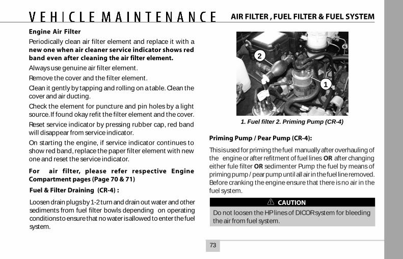
Engine Air Filter
Periodically clean air filter element and replace it with anew one when air cleaner service indicator shows redband even after cleaning the air filter element.
Always use genuine air filter element.
Remove the cover and the filter element.
Clean it gently by tapping and rolling on a table. Clean thecover and air ducting.
Check the element for puncture and pin holes by a lightsource. If found okay refit the filter element and the cover.
Reset service indicator by pressing rubber cap, red bandwill disappear from service indicator.
On starting the engine, if service indicator continues toshow red band, replace the paper filter element with newone and reset the service indicator.
For air filter, please refer respective EngineCompartment pages (Page 70 & 71)
Fuel & Filter Draining (CR-4) :
Loosen drain plugs by 1-2 turn and drain out water and othersediments from fuel filter bowls depending on operatingconditions to ensure that no water is allowed to enter the fuelsystem.
Priming Pump / Pear Pump (CR-4):
This is used for priming the fuel manually after overhauling ofthe engine or after refitment of fuel lines OR after changingeither fule filter OR sedimenter Pump the fuel by means ofpriming pump / pear pump until all air in the fuel line removed.Before cranking the engine ensure that there is no air in thefuel system.
CAUTION
Do not loosen the HP lines of DICOR system for bleedingthe air from fuel system.
2
1
1. Fuel filter 2. Priming Pump (CR-4)
AIR FILTER , FUEL FILTER & FUEL SYSTEM
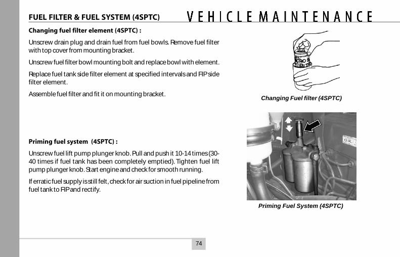
74
FUEL FILTER & FUEL SYSTEM (4SPTC)
Changing fuel filter element (4SPTC) :
Unscrew drain plug and drain fuel from fuel bowls. Remove fuel filterwith top cover from mounting bracket.
Unscrew fuel filter bowl mounting bolt and replace bowl with element.
Replace fuel tank side filter element at specified intervals and FIP sidefilter element.
Assemble fuel filter and fit it on mounting bracket.
Priming fuel system (4SPTC) :
Unscrew fuel lift pump plunger knob. Pull and push it 10-14 times (30-40 times if fuel tank has been completely emptied). Tighten fuel liftpump plunger knob. Start engine and check for smooth running.
If erratic fuel supply is still felt, check for air suction in fuel pipeline fromfuel tank to FIP and rectify.
Changing Fuel filter (4SPTC)
Priming Fuel System (4SPTC)
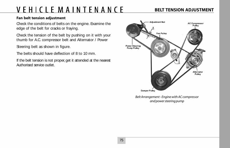
75
BELT TENSION ADJUSTMENT
Fan belt tension adjustment
Check the conditions of belts on the engine. Examine theedge of the belt for cracks or fraying.
Check the tension of the belt by pushing on it with yourthumb for A.C. compressor belt and Alternator / Power
Steering belt as shown in figure.
The belts should have deflection of 8 to 10 mm.
If the belt tension is not proper, get it attended at the nearestAuthorised service outlet.
Belt Arrangement - Engine with AC compressorand power steering pump
76
Bleeding clutch system
A dry friction, single disc, diaphragm type clutch has beenfitted which is actuated hydraulically.
The procedure for bleeding the system is as follows :
a Ensure that fluid level in clutch fluid container is uptomaximum level.
b. Remove dust cap from slave cylinder bleed screw andclean the screw thoroughly. Attach bleeding tube to bleedscrew and place other end of tube in a clean glass jarcontaining sufficient clutch fluid to submerge tube endholding the jar just above the bleed screw level.
c. Pump clutch pedal twice or thrice slowly throughout itsstroke and by holding clutch pedal in depressed condition,loosen bleed screw on slave cylinder, Watch for air bubblesin glass jar.
d. Retighten bleed screw on slave cylinder and repeat theprocess until air bubbles cease to appear at the end oftube in glass jar, allowing only fluid to flow.
e. After completing bleeding operation, ensure that bleedscrew on slave cylinder is fully tightened. Replace dustcap on the bleed screw.
BLEEDING CLUTCH SYSTEM
During bleeding process keep a watch on fluid level incontainer and top-up.
For Clutch Fluid Container location, please referrespective Engine Compartment pages (Page 70 & 71)
77
ENGINE COOLING SYSTEM
Cooling system :
If engine overheating occurs, there could be a fault in thecooling system which may be on account of :1. Less coolant in the system or dirt/ scale having
accumulated inside coolant passages, especially in theradiator core.
2. Chocking of radiator passages due to foreign material ordamages.
3. Defective/stuck thermostat.4. Loose fan drive belt.5. Coolant leakage from system.
Always use genuine radiator cap of 1.0 kg/cm2 ( 14 psi ), ifrequired to be replaced. A proper radiator cap firmly fittedmaintains pressure in the cooling system.
Prevention of rust formation :Use genuine co-branded premixed coolant in the coolingsystem to prevent rust formation and freezing of coolant insidethe crankcase passages.Fill the engine coolant auxiliary tank upto ‘FULL’ mark.
Changing of coolant in the cooling system :
a. Drain the cooling system and flush it with clean water.b. Pour the genuine co-branded coolant into the radiator until it is
full.
c. Start the engine. Top up the radiator with coolant.d. Fill the auxiliary tank upto ‘FULL’ mark.e. Ensure no leakage in the system.
For Engine Coolant Tank location, please refer respectiveEngine Compartment pages (Page 70 & 71)
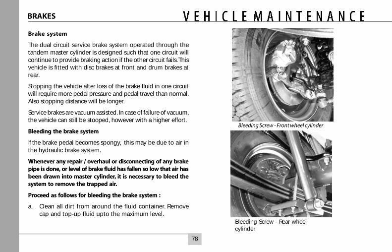
78
Brake system
The dual circuit service brake system operated through thetandem master cylinder is designed such that one circuit willcontinue to provide braking action if the other circuit fails. Thisvehicle is fitted with disc brakes at front and drum brakes atrear.
Stopping the vehicle after loss of the brake fluid in one circuitwill require more pedal pressure and pedal travel than normal.Also stopping distance will be longer.
Service brakes are vacuum assisted. In case of failure of vacuum,the vehicle can still be stooped, however with a higher effort.
Bleeding the brake system
If the brake pedal becomes spongy, this may be due to air inthe hydraulic brake system.
Whenever any repair / overhaul or disconnecting of any brakepipe is done, or level of brake fluid has fallen so low that air hasbeen drawn into master cylinder, it is necessary to bleed thesystem to remove the trapped air.
Proceed as follows for bleeding the brake system :
a. Clean all dirt from around the fluid container. Removecap and top-up fluid upto the maximum level.
Bleeding Screw - Front wheel cylinder
Bleeding Screw - Rear wheelcylinder
BRAKES
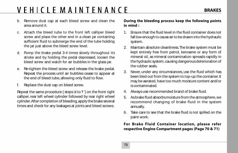
79
BRAKES
b. Remove dust cap at each bleed screw and clean thearea around it.
c. Attach the bleed tube to the front left calliper bleedscrew and place the other end in a clean jar containingsufficient fluid to submerge the end of the tube holdingthe jar just above the bleed screw level.
d. Pump the brake pedal 3-4 times slowly throughout itsstroke and by holding the pedal depressed, loosen thebleed screw and watch for air bubbles in the glass jar.
e. Re-tighten the bleed screw and release the brake pedal.Repeat the process until air bubbles cease to appear atthe end of bleed tube, allowing only fluid to flow.
f. Replace the dust cap on bleed screw.
Repeat the same procedure ( steps ‘a’ to ‘f ’) on the front rightcalliper, rear left wheel cylinder followed by rear right wheelcylinder. After completion of bleeding, apply the brake severaltimes and check for any leakages at joints and bleed screws.
During the bleeding process keep the following pointsin mind :
1. Ensure that the fluid level in the fluid container does notfall low enough to cause air to be drawn into the hydraulicsystem.
2. Maintain absolute cleanliness. The brake system must bekept entirely free from petrol, kerosene or any form ofmineral oil, as mineral contamination spreads rapidly inthe hydraulic system, causing dangerous deterioration ofthe rubber seals.
3. Never, under any circumstances, use the fluid which hasbeen bled out from the system to top-up the container. Itmay be aerated, have too much moisture content and/oris contaminated.
4. Always use recommended brand of brake fluid.
5. As brake fluid absorbs moisture from the atmosphere, werecommend changing of brake fluid in the systemannually.
6. Take care to see that the brake fluid is not spilled on thepaint work.
For Brake Fluid Container location, please referrespective Engine Compartment pages (Page 70 & 71)
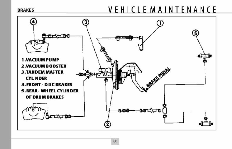
80
BRAKES
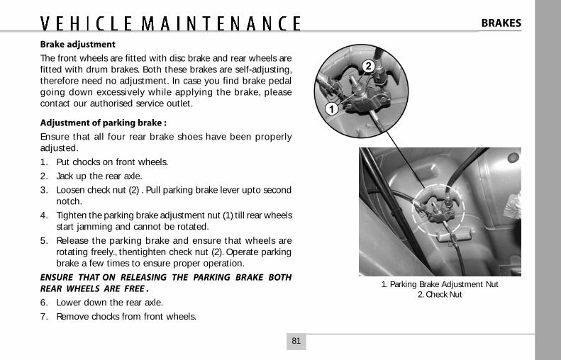
81
1. Parking Brake Adjustment Nut2. Check Nut
Brake adjustment
The front wheels are fitted with disc brake and rear wheels arefitted with drum brakes. Both these brakes are self-adjusting,therefore need no adjustment. In case you find brake pedalgoing down excessively while applying the brake, pleasecontact our authorised service outlet.
Adjustment of parking brake :
Ensure that all four rear brake shoes have been properlyadjusted.
1. Put chocks on front wheels.
2. Jack up the rear axle.
3. Loosen check nut (2) . Pull parking brake lever upto secondnotch.
4. Tighten the parking brake adjustment nut (1) till rear wheelsstart jamming and cannot be rotated.
5. Release the parking brake and ensure that wheels arerotating freely., thentighten check nut (2). Operate parkingbrake a few times to ensure proper operation.
ENSURE THAT ON RELEASING THE PARKING BRAKE BOTHREAR WHEELS ARE FREE .
6. Lower down the rear axle.
7. Remove chocks from front wheels.
BRAKES
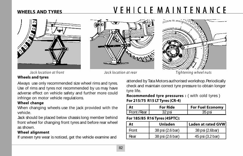
82
Wheels and tyres
Always use only recommended size wheel rims and tyres.Use of rims and tyres not recommended by us may haveadverse effect on vehicle safety and further more couldinfringe on motor vehicle regulations.Wheel changeWhen changing wheels use the jack provided with thevehicle.Jack should be placed below chassis long member behindfront wheel for changing front tyres and before rear wheelas shown.Wheel alignmentIf uneven tyre wear is noticed, get the vehicle examine and
attended by Tata Motors authorised workshop. Periodicallycheck and maintain correct tyre pressure to obtain longertyre life.Recommended tyre pressures : ( with cold tyres )For 215/75 R15 LT Tyres (CR-4)
At For Ride For Fuel EconomyFront /Rear 32 psi 35 psi
For 185/85 R16 Tyres (4SPTC):
At Unladen Laden at rated GVW
Front 38 psi (2.6 bar) 38 psi (2.6bar)
Rear 38 psi (2.6 bar) 45 psi (3.2 bar)
WHEELS AND TYRES
Jack location at front Jack location at rear Tightening w heel nuts
83
Check tyres for damage from time to time and removeany foreign bodies (nails/stones, metal chips etc.)embedded in treads.While fitting wheels on the vehicle make sure that wheelbolts are free from dust, scratches, dirt, dents, etc.Do not oil wheel bolts and nuts. Wipe off any adheringoil on bolts/nutsTightening torque of wheel nuts :12-15 mkg. Retightenwheel nuts after 100 km of every wheel change.New tyres do not give maximum grip straightway andshould therefore be run-in at moderate speed for thefirst 100 km. This will help to make the tyres last long.To avoid damage to tyres and wheels, drive slowly overspeed breakers / bumps / rough roads.Wheel balancingWheels of your vehicle are balanced. The same should bemaintained when repairing a tyre or tube and replacingthe tyre or rim.Repairing a tyre / tubeMark suitably the tyre position (If original colour dot markis not visible) with respect to valve stem hole to ensurethat tyre is refitted in original location. Ensure that thebalancing weights are not disturbed during removal oftyres. Check the balance weight prior to removal of tyre,if found loose, mark its location on the rim and refitproperly.
Replacing a tyre / rim.
When the tyre or rim is changed the wheel should beproperly balanced on a machine after inflating to thespecified value as per the following norms.
1. Permissible imbalance for tyre with rim = 250 gm-cmmax.
2. Permissible balance weight for tyre with rim = 140 gmmax.
3. Relocate the tyre if the weight required to balance ismore than 140 gm.
4. Balance weights are available from 10 gm to 90 gm insteps of 10 gm and from 80 to 140 gm in steps of 20 gm.
5. Do not use more than one balance weight on side.
WHEELS AND TYRES
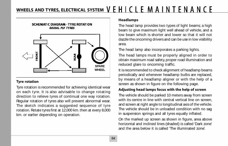
84
Tyre rotation
Tyre rotation is recommended for achieving identical wearon each tyre. It is also advisable to change rotatingdirection to relieve tyres of continual one way rotation.Regular rotation of tyres also will prevent abnormal wear.The sketch indicates a suggested sequence of tyrerotation. Rotate tyres first at 12,000 km. then at every 8,000km. or earlier depending on operation.
Headlamps
The head lamp provides two types of light beams; a highbeam to give maximum light well ahead of vehicle, and alow beam which is shorter and lower so that it will notdazzle the oncoming drivers and can be use in low visibilityarea.
The head lamp also incorporates a parking lights.
The head lamps must be properly aligned in order toobtain maximum road safety, proper road illumination andreduced glare to oncoming traffic.
It is recommended to check alignment of headlamp beamsperiodically and whenever headlamp bulbs are replaced,by means of a headlamp aligner or with the help of ascreen as shown in figure on the following page.
Adjusting head lamps focus with the help of screen
The vehicle should be parked 10 meters away from screenwith its centre in line with central vertical line on screen,and screen at right angle to longitudinal axis of the vehicle.The vehicle should be in unloaded condition with no sagin suspension springs and all tyres equally inflated.
On the marked up screen as shown in figure, area abovehorizontal and inclined lines (shaded) is called ‘Dark zone’and the area below it is called ‘The illuminated zone’.
WHEELS AND TYRES, ELECTRICAL SYSTEM
SPAREWHEEL
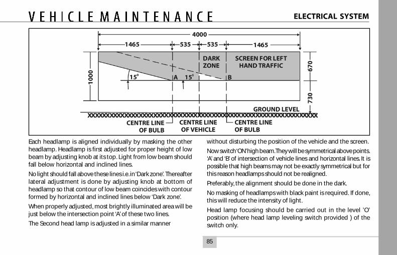
85
Each headlamp is aligned individually by masking the otherheadlamp. Headlamp is first adjusted for proper height of lowbeam by adjusting knob at its top. Light from low beam shouldfall below horizontal and inclined lines.
No light should fall above these lines i.e. in ‘Dark zone’. Thereafterlateral adjustment is done by adjusting knob at bottom ofheadlamp so that contour of low beam coincides with contourformed by horizontal and inclined lines below ‘Dark zone’.
When properly adjusted, most brightly illuminated area will bejust below the intersection point ‘A’ of these two lines.
The Second head lamp is adjusted in a similar manner
without disturbing the position of the vehicle and the screen.
Now switch ‘ON’ high beam. They will be symmetrical above points.‘A’ and ‘B’ of intersection of vehicle lines and horizontal lines. It ispossible that high beams may not be exactly symmetrical but forthis reason headlamps should not be realigned.
Preferably, the alignment should be done in the dark.
No masking of headlamps with black paint is required. If done,this will reduce the intensity of light.
Head lamp focusing should be carried out in the level ’O’position (where head lamp leveling switch provided ) of theswitch only.
ELECTRICAL SYSTEM
86
Head lamp bulb replacement
Raise the bonnet of the vehicle. Remove the rear protectivecover. Pull out cable socket from bulb. Remove lock ring holdingthe bulb and remove the bulb.
Install new bulb, properly locating it in the housing. Fit backlocking ring, cable socket and protective cover.
Realign headlamp beam after replacing bulb.
Do not clean the reflector as it will cause damage to mirror -finished surface. Do not replace bulb with dirty or oily hands,since oil will evaporate due to bulb heat and stain the reflector.
ELECTRICAL SYSTEM
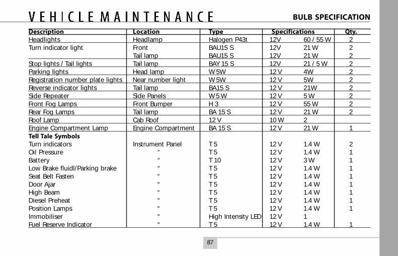
87
Description Location Type Specifications Qty.Headlights Headlamp Halogen P43t 12V 60 / 55 W 2Turn indicator light Front BAU15 S 12V 21 W 2
Tail lamp BAU15 S 12V 21 W 2Stop lights / Tail lights Tail lamp BAY 15 S 12V 21 / 5 W 2Parking lights Head lamp W 5W 12 V 4W 2Registration number plate lights Near number light W 5W 12 V 5W 2Reverse indicator lights Tail lamp BA15 S 12 V 21W 2Side Repeater Side Panels W 5 W 12 V 5 W 2Front Fog Lamps Front Bumper H 3 12 V 55 W 2Rear Fog Lamps Tail lamp BA 15 S 12 V 21 W 2Roof Lamp Cab Roof 12 V 10 W 2Engine Compartment Lamp Engine Compartment BA 15 S 12 V 21 W 1Tell Tale SymbolsTurn indicators Instrument Panel T 5 12 V 1.4 W 2Oil Pressure “ T 5 12 V 1.4 W 1Battery “ T 10 12 V 3 W 1Low Brake fluidl/Parking brake “ T 5 12 V 1.4 W 1Seat Belt Fasten “ T 5 12 V 1.4 W 1Door Ajar “ T 5 12 V 1.4 W 1High Beam “ T 5 12 V 1.4 W 1Diesel Preheat “ T 5 12 V 1.4 W 1Position Lamps “ T 5 12 V 1.4 W 1Immobiliser “ High Intensity LED 12 V 1Fuel Reserve Indicator “ T 5 12 V 1.4 W 1
BULB SPECIFICATION
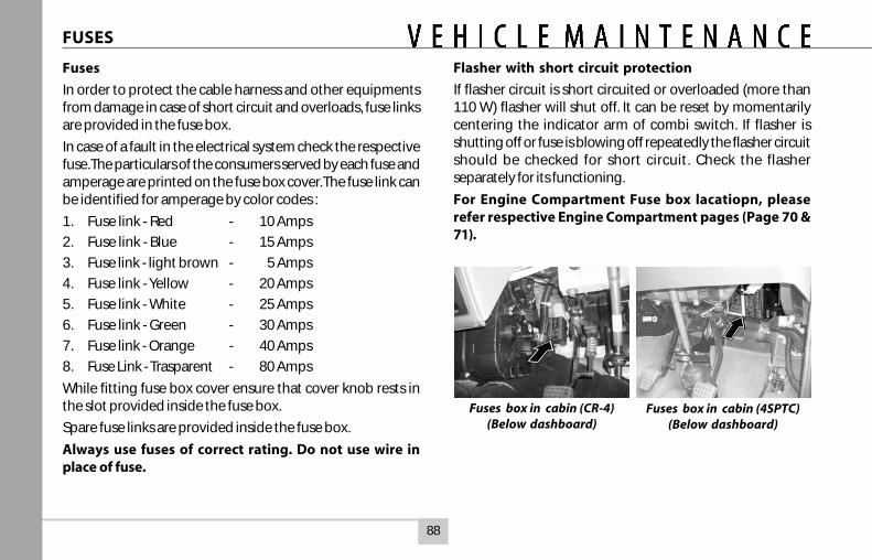
88
Fuses
In order to protect the cable harness and other equipmentsfrom damage in case of short circuit and overloads, fuse linksare provided in the fuse box.
In case of a fault in the electrical system check the respectivefuse. The particulars of the consumers served by each fuse andamperage are printed on the fuse box cover. The fuse link canbe identified for amperage by color codes :
1. Fuse link - Red - 10 Amps
2. Fuse link - Blue - 15 Amps
3. Fuse link - light brown - 5 Amps
4. Fuse link - Yellow - 20 Amps
5. Fuse link - White - 25 Amps
6. Fuse link - Green - 30 Amps
7. Fuse link - Orange - 40 Amps
8. Fuse Link - Trasparent - 80 Amps
While fitting fuse box cover ensure that cover knob rests inthe slot provided inside the fuse box.
Spare fuse links are provided inside the fuse box.
Always use fuses of correct rating. Do not use wire inplace of fuse.
FUSES
Flasher with short circuit protection
If flasher circuit is short circuited or overloaded (more than110 W) flasher will shut off. It can be reset by momentarilycentering the indicator arm of combi switch. If flasher isshutting off or fuse is blowing off repeatedly the flasher circuitshould be checked for short circuit. Check the flasherseparately for its functioning.
For Engine Compartment Fuse box lacatiopn, pleaserefer respective Engine Compartment pages (Page 70 &71).
Fuses box in cabin (CR-4)(Below dashboard)
Fuses box in cabin (4SPTC)(Below dashboard)
89
CARE AND CLEANING OF VEHICLE
Care and cleaning of the vehicle
CAUTION
When cleaning the interior / exterior of the vehicle, NEVERUSE volatile solvents such as thinner, petrol or any othercleaning materials such as bleaches or strong householddetergents. These materials may be poisonous or flammableand their improper use may cause personal injury ordamage to the vehicle.
Cleaning of vehicle interior
Floor mat
Dirt can be removed from the mat with water and mildsoap. Use a brush to help loosen dirt. After dirt is loosened,wash the mat thoroughly with water and dry it in theshade.
Seat belt
Clean the seat belts with a mild soap and water only. Nobleach or dye should be used as this may weaken the beltfabric. The belts should be allowed to dry in the shade.
Upholstery
Prepare a solution of soap or neutral detergent mixedwith warm water. Apply solution with a sponge or softcloth and let it soak for a few minutes to loosen dirt. Wipethe surface with a clean, damp cloth to remove dirt and
soap solution. If some dirt still remains on the surface,repeat the procedure
Carpets
Remove dirt as much as possible by using a vacuumcleaner. Rub the stained area with clean cloth made dampwith soap to absorb the stain and remove the soap. Repeatuntil the stain is removed.
You can use commercially available carpet cleaner. In thiscase, carefully follow the manufacturer’s instructions andprecautions.
Cleaning exterior of the vehicle
Dirt or any other foreign material on the painted surfacemay result in :
Faded paint.
Rust on body due to deteriorated paint film.
Rust due to scratches
Body rust due to contact with damp dirt trapped in thebody.
Therefore it is important that your vehicle is always kept cleanand free from dirt in order to maintain the paint in a goodcondition and to protect the entire body against corrosion.
90
CARE AND CLEANING OF VEHICLE
Warning
After washing, check that the brakes are dry. If brakes are notdry, dry them by gently, repeatedly applying while driving atlow speeds.
Washing the vehicle exterior
After washing the vehicle, waxing and polishing are recom-mended to protect and beautify the paint.
Use only good quality waxes and polishes.
When using waxes and polishes, the precautions specifiedby the manufacturers should be observed.
Chrome plated parts should also be waxed.
Protection against corrosion :
The following cause corrosion :
Moisture trapped in body cavities.
Dirt and salts collected in hollows on the underside of thevehicle.
Removal of paint and protective coatings from the exteriorand underside of the vehicle.
Washing :
When washing the vehicle, follow the instructions given below.
Flush underside of body and wheel housing withpressurised water to remove mud and debris. Use plentyof water to loosen and remove dirt.
Remove dirt and mud from body exterior with runningwater. Use a soft sponge, brush with water. Do not use hardmaterial which can scratch the paint.
Wash the exterior with water, lightly rubbing with spongeor soft cloth. The sponge or cloth should frequently soakedin water.
CAUTION
When using commercial wash products precautions speci-fied by the manufacturer should be observed. Do not usestrong household detergents or soaps.
Once dirt has been completely removed, wash off withrunning hose water.
After rinsing, wipe the body lightly with wet chamois orcloth and allow the body to dry it in the shade.
91
CARE AND CLEANING OF VEHICLE
Corrosion preventive measures have been incorporatedin your vehicle. You can avoid corrosion of your vehicle byperforming some simple periodic maintenance :
Repair chips and scratches in the paint as soon as youdiscover them.
Inspect and clean the drain holes in the bottom of thedoors and body.
Check the floor coverings for dampness. Carpets and floormats remain damp for a long time, especially in winter. Thiscan eventually cause the floor panels to corrode.
Use a high pressure spray to clean the underside of yourvehicle. This is especially important in areas near chemicaland other industries.
Have corrosion preventive coatings done on the undersideof your vehicle using Tata Motors co-branded anti corrosivetreatment.
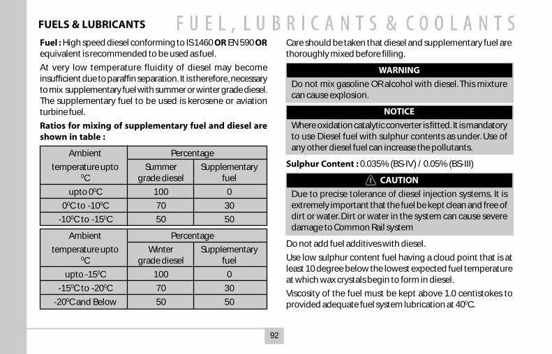
92
Fuel : High speed diesel conforming to IS 1460 OR EN 590 ORequivalent is recommended to be used as fuel.
At very low temperature fluidity of diesel may becomeinsufficient due to paraffin separation. It is therefore, necessaryto mix supplementary fuel with summer or winter grade diesel.The supplementary fuel to be used is kerosene or aviationturbine fuel.
Ratios for mixing of supplementary fuel and diesel areshown in table :
Ambient Percentage
temperature upto Summer Supplementary0C grade diesel fuel
upto 00C 100 0
00C to -100C 70 30
-100C to -150C 50 50
Ambient Percentage
temperature upto Winter Supplementary0C grade diesel fuel
upto -150C 100 0
-150C to -200C 70 30
-200C and Below 50 50
Care should be taken that diesel and supplementary fuel arethoroughly mixed before filling.
WARNING
Do not mix gasoline OR alcohol with diesel. This mixturecan cause explosion.
NOTICE
Where oxidation catalytic converter is fitted. It is mandatoryto use Diesel fuel with sulphur contents as under. Use ofany other diesel fuel can increase the pollutants.
Sulphur Content : 0.035% (BS-IV) / 0.05% (BS-III)
CAUTION
Due to precise tolerance of diesel injection systems. It isextremely important that the fuel be kept clean and free ofdirt or water. Dirt or water in the system can cause severedamage to Common Rail system
Do not add fuel additives with diesel.
Use low sulphur content fuel having a cloud point that is atleast 10 degree below the lowest expected fuel temperatureat which wax crystals begin to form in diesel.
Viscosity of the fuel must be kept above 1.0 centistokes toprovided adequate fuel system lubrication at 400C.
FUELS & LUBRICANTS
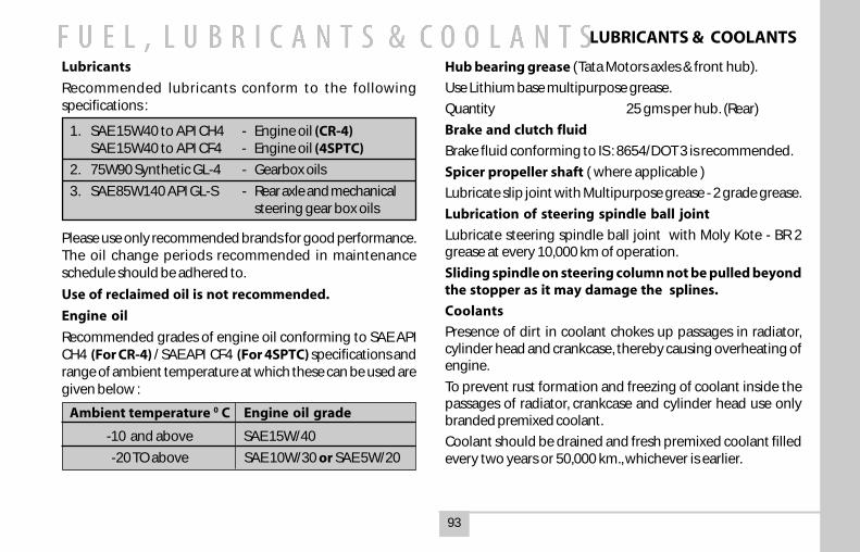
93
Lubricants
Recommended lubricants conform to the followingspecifications :
1. SAE 15W40 to API CH4 - Engine oil (CR-4)SAE 15W40 to API CF4 - Engine oil (4SPTC)
2. 75W90 Synthetic GL-4 - Gearbox oils
3. SAE 85W140 API GL-S - Rear axle and mechanicalsteering gear box oils
Please use only recommended brands for good performance.The oil change periods recommended in maintenanceschedule should be adhered to.
Use of reclaimed oil is not recommended.
Engine oil
Recommended grades of engine oil conforming to SAE APICH4 (For CR-4) / SAE API CF4 (For 4SPTC) specifications andrange of ambient temperature at which these can be used aregiven below :
Ambient temperature 0 C Engine oil grade
-10 and above SAE 15W/40
-20 TO above SAE 10W/30 or SAE 5W/20
Hub bearing grease (Tata Motors axles & front hub).
Use Lithium base multipurpose grease.
Quantity 25 gms per hub. (Rear)
Brake and clutch fluid
Brake fluid conforming to IS : 8654/DOT 3 is recommended.
Spicer propeller shaft ( where applicable )
Lubricate slip joint with Multipurpose grease - 2 grade grease.
Lubrication of steering spindle ball joint
Lubricate steering spindle ball joint with Moly Kote - BR 2grease at every 10,000 km of operation.
Sliding spindle on steering column not be pulled beyondthe stopper as it may damage the splines.
Coolants
Presence of dirt in coolant chokes up passages in radiator,cylinder head and crankcase, thereby causing overheating ofengine.
To prevent rust formation and freezing of coolant inside thepassages of radiator, crankcase and cylinder head use onlybranded premixed coolant.
Coolant should be drained and fresh premixed coolant filledevery two years or 50,000 km., whichever is earlier.
LUBRICANTS & COOLANTS
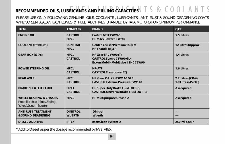
94
PLEASE USE ONLY FOLLOWING GENUINE OILS, COOLANTS , LUBRICANTS , ANTI RUST & SOUND DEADENING COATS,WINDSCREEN SEALANT, ADHESIVES & FUEL ADDITIVES BRANDED BY TATA MOTORS FOR OPTIMUM PERFORMANCE
RECOMMENDED OILS, LUBRICANTS AND FILLING CAPACITIES
ITEM COMPANY BRAND QTY
ENGINE OIL CASTROL Castrol GTD 15W/40 5.5 LitresHPCL HP Milcy Power 15 W/40
COOLANT (Premixed) SUNSTAR Golden Cruiser Premium 1400 M 12 Litres (Approx)HPCL HP Thanda Raja P
GEAR BOX (G-76) HPCL HP Gear EP 75W90 (T) 1.4 LitresCASTROL CASTROL Syntro 75W90 GL4
Exxon Mobil - MobiLube 1 SHC 75W90
POWER STEERING OIL HPCL HP-ATF 1.6 LitresCASTROL CASTROL Transpower TQ
REAR AXLE HPCL HP Gear Oil XP 85W140 GL5 2.2 Litres (CR-4)CASTROL CASTROL Extreme Pressure 85W140 1.9 Litres (4SPTC)
BRAKE / CLUTCH FLUID HP CL HP Super Duty Brake Fluid DOT - 3 As requiredCASTROL CASTROL Universal Brake Fluid DOT - 3
WHEEL BEARING & CHASSIS HPCL HP Multipurpose Grease-2 As requiredPropeller shaft joints, SlidingYokes, Vacuum Booster
ANTI RUST TREATMENT DINITROL Dinitrol —& SOUND DEADENING WUERTH Wuerth —
DIESEL ADDITIVE IFTEX Iftex Clean System D 250 ml pack *
* Add to Diesel as per the dosage recommended by M/s IFTEX
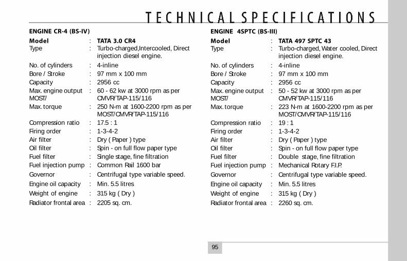
95
ENGINE CR-4 (BS-IV)
Model : TATA 3.0 CR4Type : Turbo-charged,Intercooled, Direct
injection diesel engine.
No. of cylinders : 4-inlineBore / Stroke : 97 mm x 100 mmCapacity : 2956 ccMax. engine output : 60 - 62 kw at 3000 rpm as perMOST/ CMVR/TAP-115/116Max. torque : 250 N-m at 1600-2200 rpm as per
MOST/CMVR/TAP-115/116Compression ratio : 17.5 : 1Firing order : 1-3-4-2Air filter : Dry ( Paper ) typeOil filter : Spin - on full flow paper typeFuel filter : Single stage, fine filtrationFuel injection pump : Common Rail 1600 bar
Governor : Centrifugal type variable speed.
Engine oil capacity : Min. 5.5 litres
Weight of engine : 315 kg ( Dry )
Radiator frontal area : 2205 sq. cm.
ENGINE 4SPTC (BS-III)
Model : TATA 497 SPTC 43Type : Turbo-charged, Water cooled, Direct
injection diesel engine.
No. of cylinders : 4-inlineBore / Stroke : 97 mm x 100 mmCapacity : 2956 ccMax. engine output : 50 - 52 kw at 3000 rpm as perMOST/ CMVR/TAP-115/116Max. torque : 223 N-m at 1600-2200 rpm as per
MOST/CMVR/TAP-115/116Compression ratio : 19 : 1Firing order : 1-3-4-2Air filter : Dry ( Paper ) typeOil filter : Spin - on full flow paper typeFuel filter : Double stage, fine filtrationFuel injection pump : Mechanical Rotary F.I.P.
Governor : Centrifugal type variable speed.
Engine oil capacity : Min. 5.5 litres
Weight of engine : 315 kg ( Dry )
Radiator frontal area : 2260 sq. cm.
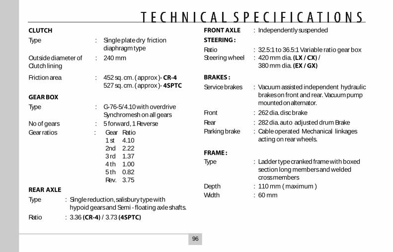
96
FRONT AXLE : Independently suspended
STEERING :
Ratio : 32.5:1 to 36.5:1 Variable ratio gear boxSteering wheel : 420 mm dia. (LX / CX) /
380 mm dia. (EX / GX)
BRAKES :
Service brakes : Vacuum assisted independent hydraulicbrakes on front and rear. Vacuum pumpmounted on alternator.
Front : 262 dia. disc brake
Rear : 282 dia. auto adjusted drum BrakeParking brake : Cable operated Mechanical linkages
acting on rear wheels.
FRAME :Type : Ladder type cranked frame with boxed
section long members and weldedcross members
Depth : 110 mm ( maximum )Width : 60 mm
CLUTCH
Type : Single plate dry frictiondiaphragm type
Outside diameter of : 240 mmClutch lining
Friction area : 452 sq. cm. ( approx )- CR-4527 sq. cm. ( approx )- 4SPTC
GEAR BOX
Type : G-76-5/4.10 with overdriveSynchromesh on all gears
No of gears : 5 forward, 1 ReverseGear ratios : Gear Ratio
1 st 4.102nd 2.223 rd 1.374 th 1.005 th 0.82Rev. 3.75
REAR AXLE
Type : Single reduction, salisbury type withhypoid gears and Semi - floating axle shafts.
Ratio : 3.36 (CR-4) / 3.73 (4SPTC)
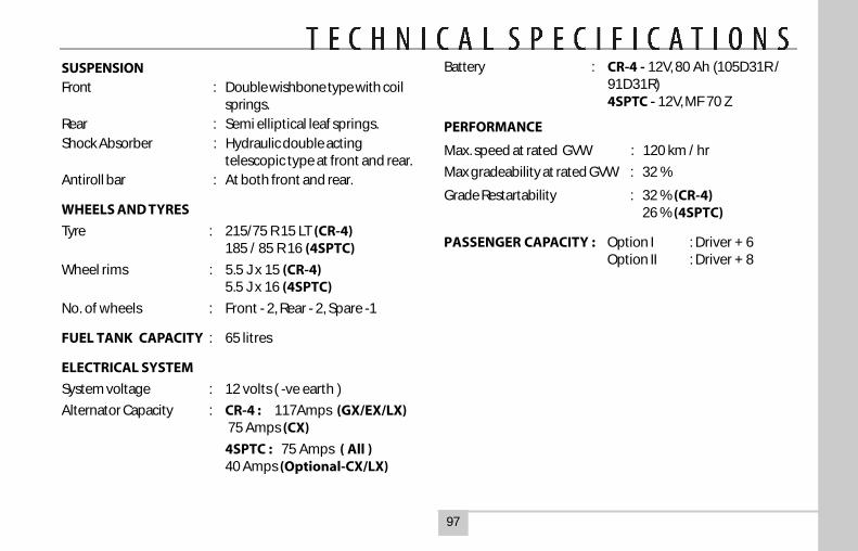
97
SUSPENSIONFront : Double wishbone type with coil
springs.Rear : Semi elliptical leaf springs.Shock Absorber : Hydraulic double acting
telescopic type at front and rear.Antiroll bar : At both front and rear.
WHEELS AND TYRES
Tyre : 215/75 R 15 LT (CR-4)185 / 85 R 16 (4SPTC)
Wheel rims : 5.5 J x 15 (CR-4)5.5 J x 16 (4SPTC)
No. of wheels : Front - 2, Rear - 2, Spare -1
FUEL TANK CAPACITY : 65 litres
ELECTRICAL SYSTEM
System voltage : 12 volts ( -ve earth )
Alternator Capacity : CR-4 : 117Amps (GX/EX/LX) 75 Amps (CX)
4SPTC : 75 Amps ( All )40 Amps (Optional-CX/LX)
Battery : CR-4 - 12V, 80 Ah (105D31R /91D31R)4SPTC - 12V, MF 70 Z
PERFORMANCE
Max. speed at rated GVW : 120 km / hr
Max gradeability at rated GVW : 32 %
Grade Restartability : 32 % (CR-4)26 % (4SPTC)
PASSENGER CAPACITY : Option I : Driver + 6Option II : Driver + 8
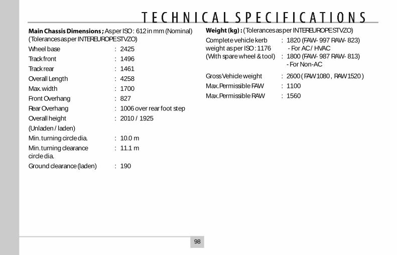
98
Main Chassis Dimensions ; As per ISO : 612 in mm (Nominal)(Tolerances as per INTEREUROPE STVZO)
Wheel base : 2425
Track front : 1496
Track rear : 1461
Overall Length : 4258
Max. width : 1700
Front Overhang : 827
Rear Overhang : 1006 over rear foot step
Overall height : 2010 / 1925
(Unladen / laden)
Min. turning circle dia. : 10.0 m
Min. turning clearance : 11.1 mcircle dia.
Ground clearance (laden) : 190
Weight (kg) : (Tolerances as per INTEREUROPE STVZO)
Complete vehicle kerb : 1820 (FAW- 997 RAW- 823)weight as per ISO : 1176 - For AC / HVAC(With spare wheel & tool) : 1800 (FAW- 987 RAW- 813)
- For Non-AC
Gross Vehicle weight : 2600 ( FAW 1080 , RAW 1520 )
Max. Permissible FAW : 1100
Max. Permissible RAW : 1560
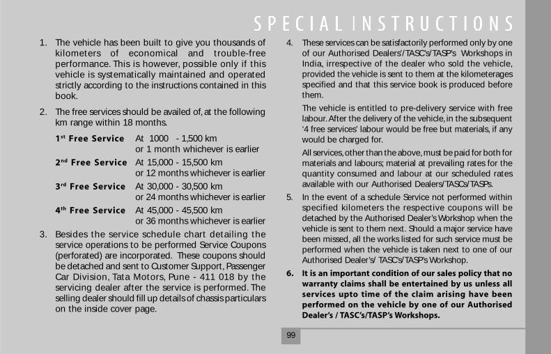
99
1. The vehicle has been built to give you thousands ofkilometers of economical and trouble-freeperformance. This is however, possible only if thisvehicle is systematically maintained and operatedstrictly according to the instructions contained in thisbook.
2. The free services should be availed of, at the followingkm range within 18 months.
1st Free Service At 1000 - 1,500 kmor 1 month whichever is earlier
2nd Free Service At 15,000 - 15,500 kmor 12 months whichever is earlier
3rd Free Service At 30,000 - 30,500 kmor 24 months whichever is earlier
4th Free Service At 45,000 - 45,500 kmor 36 months whichever is earlier
3. Besides the service schedule chart detailing theservice operations to be performed Service Coupons(perforated) are incorporated. These coupons shouldbe detached and sent to Customer Support, PassengerCar Division, Tata Motors, Pune - 411 018 by theservicing dealer after the service is performed. Theselling dealer should fill up details of chassis particularson the inside cover page.
4. These services can be satisfactorily performed only by oneof our Authorised Dealers’/TASC’s/TASP’s Workshops inIndia, irrespective of the dealer who sold the vehicle,provided the vehicle is sent to them at the kilometeragesspecified and that this service book is produced beforethem.
The vehicle is entitled to pre-delivery service with freelabour. After the delivery of the vehicle, in the subsequent‘4 free services’ labour would be free but materials, if anywould be charged for.
All services, other than the above, must be paid for both formaterials and labours; material at prevailing rates for thequantity consumed and labour at our scheduled ratesavailable with our Authorised Dealers/TASCs/TASPs.
5. In the event of a schedule Service not performed withinspecified kilometers the respective coupons will bedetached by the Authorised Dealer’s Workshop when thevehicle is sent to them next. Should a major service havebeen missed, all the works listed for such service must beperformed when the vehicle is taken next to one of ourAuthorised Dealer’s/ TASC’s/TASP’s Workshop.
6. It is an important condition of our sales policy that nowarranty claims shall be entertained by us unless allservices upto time of the claim arising have beenperformed on the vehicle by one of our AuthorisedDealer’s / TASC’s/TASP’s Workshops.
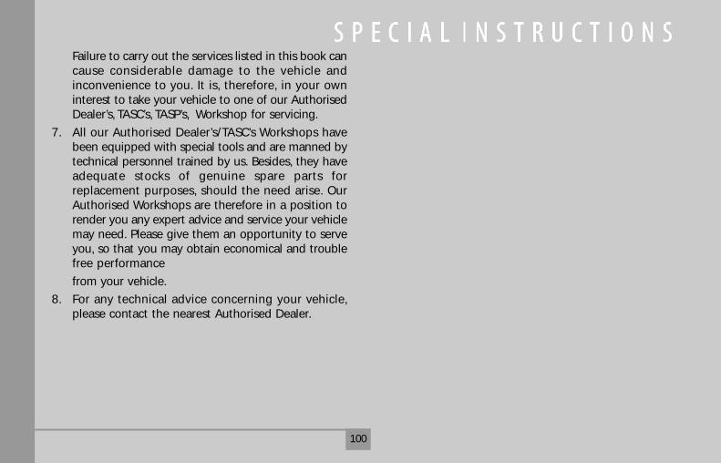
100
Failure to carry out the services listed in this book cancause considerable damage to the vehicle andinconvenience to you. It is, therefore, in your owninterest to take your vehicle to one of our AuthorisedDealer’s, TASC’s, TASP’s, Workshop for servicing.
7. All our Authorised Dealer’s/TASC’s Workshops havebeen equipped with special tools and are manned bytechnical personnel trained by us. Besides, they haveadequate stocks of genuine spare parts forreplacement purposes, should the need arise. OurAuthorised Workshops are therefore in a position torender you any expert advice and service your vehiclemay need. Please give them an opportunity to serveyou, so that you may obtain economical and troublefree performance
from your vehicle.
8. For any technical advice concerning your vehicle,please contact the nearest Authorised Dealer.
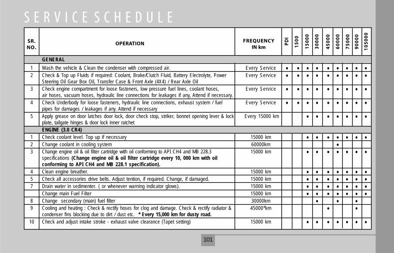
101
SR.NO.
OPERATION FREQUENCYIN km
PD
I
15
00
15
00
0
30
00
0
45
00
0
60
00
0
75
00
0
90
00
0
10
50
00
GENERAL1 Wash the vehicle & Clean the condenser with compressed air. Every Service2 Check & Top up Fluids if required: Coolant, Brake/Clutch Fluid, Battery Electrolyte, Power Every Service
Steering Oil Gear Box Oil, Transfer Case & Front Axle (4X4) / Rear Axle Oil3 Check engine compartment for loose fasteners, low pressure fuel lines, coolant hoses, Every Service
air hoses, vacuum hoses, hydraulic line connections for leakages if any, Attend if necessary.4 Check Underbody for loose fasteners, hydraulic line connections, exhaust system / fuel Every Service
pipes for damages / leakages if any. Attend if necessary5 Apply grease on door latches door lock, door check stop, striker, bonnet opening lever & lock Every 15000 km
plate, tailgate hinges & door lock inner ratchetENGINE (3.0 CR4)
1 Check coolant level. Top up if necessary 15000 km2 Change coolant in cooling system 60000km3 Change engine oil & oil filter cartridge with oil conforming to API CH4 and MB 228.3 15000 km
specifications (Change engine oil & oil filter cartridge every 10, 000 km with oilconforming to API CH4 and MB 228.1 specification).
4 Clean engine breather. 15000 km5 Check all accessories drive belts. Adjust tention, if required. Change, if damaged. 15000 km7 Drain water in sedimenter. ( or whenever warning indicator glows). 15000 km
Change main Fuel Filter 15000 km8 Change secondary (main) fuel filter 30000km9 Cooling and heating : Check & rectify hoses for clog and damage. Check & rectify radiator & 45000*km
condenser fins blocking due to dirt / dust etc. * Every 15,000 km for dusty road.10 Check and adjust intake stroke - exhaust valve clearance (Tapet setting) 15000 km
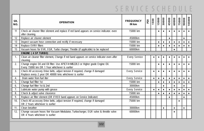
102
SR.NO.
OPERATION FREQUENCYIN km
PD
I
15
00
15
00
0
30
00
0
45
00
0
60
00
0
75
00
0
90
00
0
10
50
00
11 Check air cleaner filter element and replace if red band appears on service indicator. even 15000 kmafter cleaning.
12 Replace air cleaner element 45000km13 Inspect vacuum hose connection and rectify if necessary 15000 km14 Replace EVRV filters 15000 km15 Vacuum hoses for EVR, EGR, Turbo charger, Throttle (if applicable) to be replaced 60000km
ENGINE ( 4 SP TURBO)1. Clean air cleaner filter element, Change if red band appears on service indicator even after Every Service
cleaning2. Change engine Oil and Oil filter. Use APICF4+MB228.3 or Higher grade Engine Oil. 15000 km
Every 15000 km OR 1 Year whichever is earlier3. Check All accessory Drive belts, adjust tension if required, change if damaged Every Service
Replace every 2 year OR 40000 kms whichever is earlier4. Drain water from fuel ilter Every Service5. Change fuel filter 1st 15000 km6. Change fuel filter 1st & 2nd 30000km7. Lubricate water pump with grease Every Service8. Check & adjust valve clearance 15000 km9. Replace air filter element (OR if RED band appears on Service Indicator) 45000km
10. Check All accessory Drive belts, adjust tension if required, change if damaged 75000 kmOR 2 Years whichever is earlier
11. Clean breather 30000km12. Change vacuum hoses fotr Vacuum Modulator, Turbocharger, EGR valve & throttle valve 60000km
OR 4 Years whichever is earlier
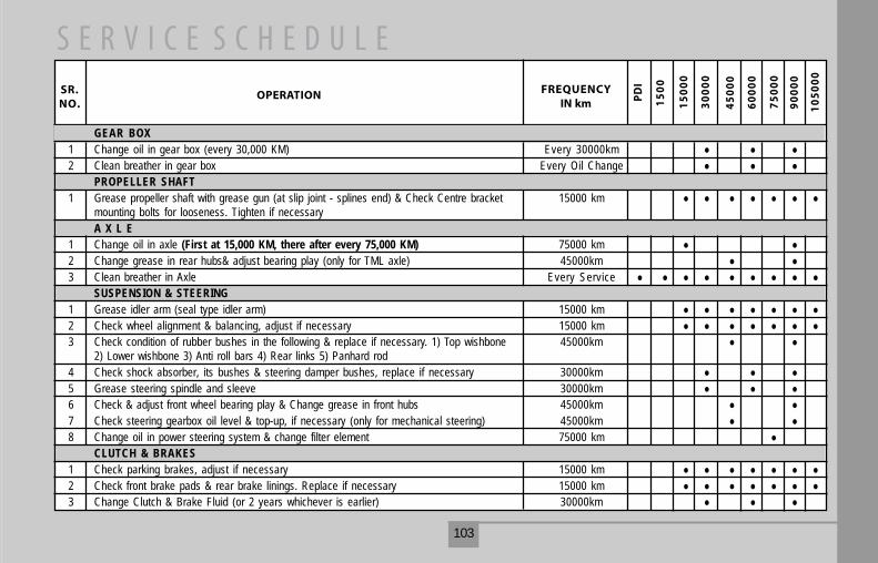
103
SR.NO.
OPERATION FREQUENCYIN km P
DI
15
00
15
00
0
30
00
0
45
00
0
60
00
0
75
00
0
90
00
0
10
50
00
GEAR BOX1 Change oil in gear box (every 30,000 KM) Every 30000km2 Clean breather in gear box Every Oil Change
PROPELLER SHAFT1 Grease propeller shaft with grease gun (at slip joint - splines end) & Check Centre bracket 15000 km
mounting bolts for looseness. Tighten if necessaryA X L E
1 Change oil in axle (First at 15,000 KM, there after every 75,000 KM) 75000 km2 Change grease in rear hubs& adjust bearing play (only for TML axle) 45000km3 Clean breather in Axle Every Service
SUSPENSION & STEERING1 Grease idler arm (seal type idler arm) 15000 km2 Check wheel alignment & balancing, adjust if necessary 15000 km3 Check condition of rubber bushes in the following & replace if necessary. 1) Top wishbone 45000km
2) Lower wishbone 3) Anti roll bars 4) Rear links 5) Panhard rod4 Check shock absorber, its bushes & steering damper bushes, replace if necessary 30000km5 Grease steering spindle and sleeve 30000km6 Check & adjust front wheel bearing play & Change grease in front hubs 45000km7 Check steering gearbox oil level & top-up, if necessary (only for mechanical steering) 45000km8 Change oil in power steering system & change filter element 75000 km
CLUTCH & BRAKES1 Check parking brakes, adjust if necessary 15000 km2 Check front brake pads & rear brake linings. Replace if necessary 15000 km3 Change Clutch & Brake Fluid (or 2 years whichever is earlier) 30000km
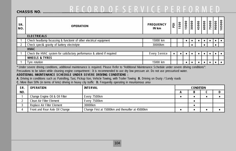
104
CHASSIS NO. ...........................................................
SR.NO.
OPERATION FREQUENCYIN km P
DI
15
00
15
00
0
30
00
0
45
00
0
60
00
0
75
00
0
90
00
0
10
50
00
ELECTRICALS1 Check headlamp focussing & functionir of other electrical equipment 15000 km2 Check speci& gravity of battery electrolyte 30000km
HVAC1 Check the HVAC system for satisfactory performance & attend if required Every Service
WHEELS & TYRES1 Tyre rotation 15000 km
* Under severe driving conditions, additional maintenance is required. Please Refer to “Additional Maintenance Schedule under severe driving conditions”:Precautions to be taken while cleaning engine compartment : It is recommended to use dry low pressure air. Do not use pressurised water.ADDITIONAL MAINTENANCE SCHEDULE UNDER SEVERE DRIVING CONDITIONS :A. Driving in conditions such as Patrolling, Taxi, Pickup Van, Vehicle Towing, with Trailer Towing B. Driving on Dusty / Sandy roadsC. More than 50% (in terms of kms) driving in heavy city traffic D. Frequently operating in mountainous area
SR. OPERATION INTERVAL CONDITIONNO. A B C D
1 Change Engine Oil & Oil Filter Every 7500km2 Clean Air Filter Element Every 7500km3 Replace Air Filter Element 30000km4 Front and Rear Axle Oil Change Change First at 15000km and thereafter at 45000km
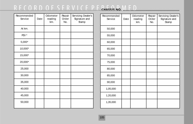
105
CHASSIS NO. ...........................................................
Recommended Odometer Repair Servicing Dealer’sService Date reading Order Signature and
km. No. Stamp
At km.
PDI *
5,000*
10,000*
15,000*
20,000*
25,000
30,000
35,000
40,000
45,000
50,000
Recommended Odometer Repair Servicing Dealer’sService Date reading Order Signature and
km. No. Stamp
50,000
55,000
60,000
65,000
70,000
75,000
80,000
85,000
90,000
1,05,000
1,20,000
1,35,000
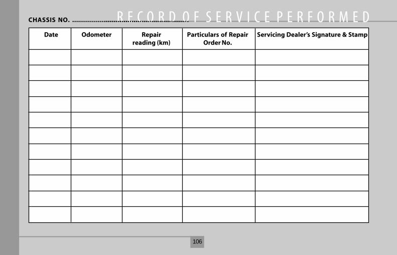
106
Date Odometer Repair Particulars of Repair Servicing Dealer’s Signature & Stampreading (km) Order No.
CHASSIS NO. ...........................................................
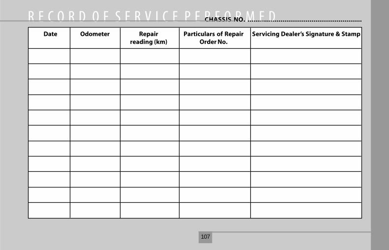
107
Date Odometer Repair Particulars of Repair Servicing Dealer’s Signature & Stampreading (km) Order No.
CHASSIS NO. ...........................................................
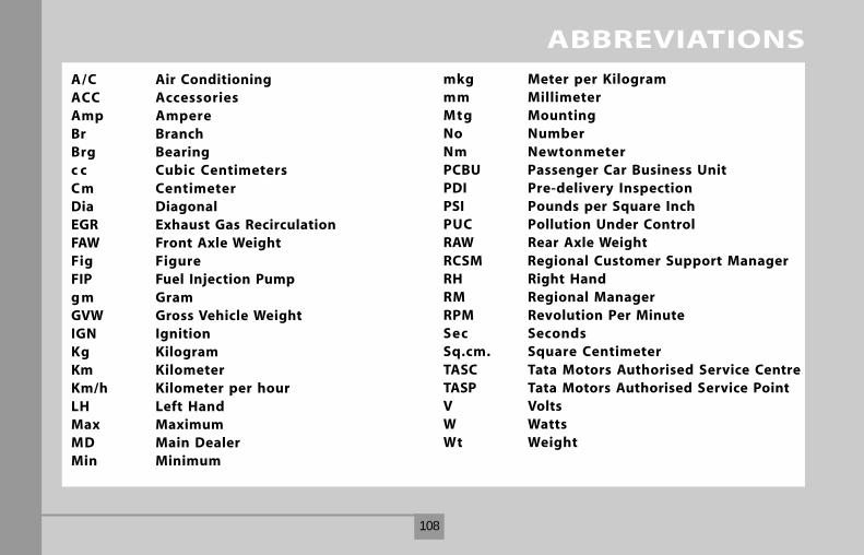
108
A/C Air ConditioningACC AccessoriesAmp AmpereBr BranchBrg Bearingc c Cubic CentimetersC m CentimeterDia DiagonalEGR Exhaust Gas RecirculationFAW Front Axle WeightFig FigureFIP Fuel Injection Pumpg m GramGVW Gross Vehicle WeightIGN IgnitionKg KilogramKm KilometerKm/h Kilometer per hourLH Left HandMax MaximumMD Main DealerMin Minimum
mkg Meter per Kilogrammm MillimeterMtg MountingNo NumberNm NewtonmeterPCBU Passenger Car Business UnitPDI Pre-delivery InspectionPSI Pounds per Square InchPUC Pollution Under ControlRAW Rear Axle WeightRCSM Regional Customer Support ManagerRH Right HandRM Regional ManagerRPM Revolution Per MinuteSec SecondsSq.cm. Square CentimeterTASC Tata Motors Authorised Service CentreTASP Tata Motors Authorised Service PointV VoltsW WattsWt Weight
ABBREVIATIONS

109
AAggregate Numbering 14
Accessory Switches 43Air Conditioning 55
Anti-theft Device 16
Ash Tray 46
BBonnet Opening & Closing 47
Brake Adjustment 79Brake Clutch System Bleeding 75
Brake System 77
Braking 62Bulb Specification 85
CCatalytic Converter 51Changing Engine Oil 71
Changing Oil Filter 71
Combi-Switch 37Coolants 92
Cooling System 76
DDo’s 10
Don’ts 13Door Locking 17
Driver’s & Co-driver’s Seat 21
Driving Climbing Sharp Gradients 65Driving Descending SharpGradients 66
Driving at Night 65
Driving Controls 26Driving Instruction 61
Driving on a Rainy Day 64
Driving on Sandy or Muddy Roads63Driving on Snowy or Icy Roads 63
Driving Safety 68
Driving Through Water 64
EEGR System 51
Engine Air Filter 72Engine Compartment Lamp 39
Engine Compartment 70
Environment Protection 6
FFan Belt Tension Adjustment 74
Fuel Economy 62Fuel Filter & Fuel Filter Draining 73
Fuel Flap Opening 47
Fuel 91Fuses 86
GGauges 34
Gear Shift lever 48
HHead Lamp Adjustment 82
Head Lamp Bulb Replacement 84Head restraint 25
Headlamp Leveling Switch 42
Headlamps 82High Mounted Stop Lamp 40
ALPHABETICAL INDEX
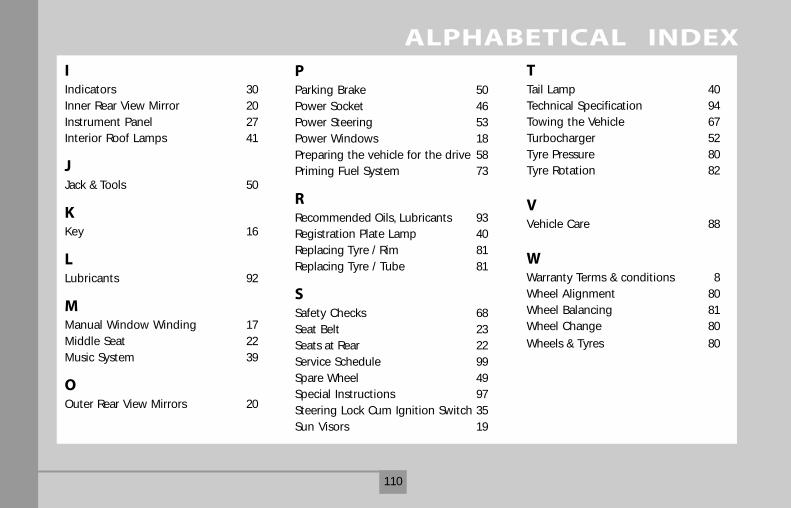
110
IIndicators 30
Inner Rear View Mirror 20
Instrument Panel 27Interior Roof Lamps 41
JJack & Tools 50
KKey 16
LLubricants 92
MManual Window Winding 17
Middle Seat 22
Music System 39
OOuter Rear View Mirrors 20
PParking Brake 50
Power Socket 46Power Steering 53
Power Windows 18
Preparing the vehicle for the drive 58Priming Fuel System 73
RRecommended Oils, Lubricants 93Registration Plate Lamp 40
Replacing Tyre / Rim 81
Replacing Tyre / Tube 81
SSafety Checks 68
Seat Belt 23Seats at Rear 22
Service Schedule 99
Spare Wheel 49Special Instructions 97
Steering Lock Cum Ignition Switch 35
Sun Visors 19
TTail Lamp 40
Technical Specification 94Towing the Vehicle 67
Turbocharger 52
Tyre Pressure 80Tyre Rotation 82
VVehicle Care 88
WWarranty Terms & conditions 8
Wheel Alignment 80
Wheel Balancing 81Wheel Change 80
Wheels & Tyres 80
ALPHABETICAL INDEX
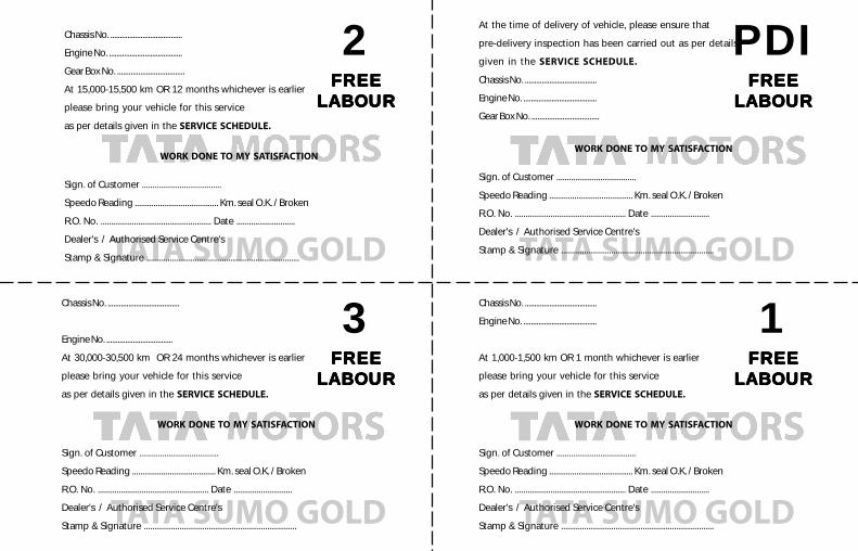
2FREEFREEFREEFREEFREE
LABOURLABOURLABOURLABOURLABOUR
PDIFREEFREEFREEFREEFREE
LABOURLABOURLABOURLABOURLABOUR
3FREEFREEFREEFREEFREE
LABOURLABOURLABOURLABOURLABOUR
1FREEFREEFREEFREEFREE
LABOURLABOURLABOURLABOURLABOUR
TATA SUMO GOLD TATA SUMO GOLD
TATA SUMO GOLDTATA SUMO GOLD
Chassis No. ......................................
Engine No. .......................................
Gear Box No. ...................................
At 15,000-15,500 km OR 12 months whichever is earlier
please bring your vehicle for this service
as per details given in the SERVICE SCHEDULE.
WORK DONE TO MY SATISFACTION
Sign. of Customer ......................................
Speedo Reading ........................................ Km. seal O.K. / Broken
R.O. No. ..................................................... Date ............................
Dealer's / Authorised Service Centre's
Stamp & Signature .........................................................................
At the time of delivery of vehicle, please ensure that
pre-delivery inspection has been carried out as per details
given in the SERVICE SCHEDULE.
Chassis No. ......................................
Engine No. .......................................
Gear Box No. ...................................
WORK DONE TO MY SATISFACTION
Sign. of Customer ......................................
Speedo Reading ........................................ Km. seal O.K. / Broken
R.O. No. ..................................................... Date ............................
Dealer's / Authorised Service Centre's
Stamp & Signature .........................................................................
Chassis No. ......................................
Engine No. .......................................
At 1,000-1,500 km OR 1 month whichever is earlier
please bring your vehicle for this service
as per details given in the SERVICE SCHEDULE.
WORK DONE TO MY SATISFACTION
Sign. of Customer ......................................
Speedo Reading ........................................ Km. seal O.K. / Broken
R.O. No. ..................................................... Date ............................
Dealer's / Authorised Service Centre's
Stamp & Signature .........................................................................
Chassis No. ......................................
Engine No. ...................................
At 30,000-30,500 km OR 24 months whichever is earlier
please bring your vehicle for this service
as per details given in the SERVICE SCHEDULE.
WORK DONE TO MY SATISFACTION
Sign. of Customer ......................................
Speedo Reading ........................................ Km. seal O.K. / Broken
R.O. No. ..................................................... Date ............................
Dealer's / Authorised Service Centre's
Stamp & Signature .........................................................................
TATA SUMO GOLD
4FREEFREEFREEFREEFREE
LABOURLABOURLABOURLABOURLABOUR
Chassis No. ......................................
Engine No. .......................................
At 45,000-45,500 km OR 36 months whichever is earlier
please bring your vehicle for this service
as per details given in the SERVICE SCHEDULE.
WORK DONE TO MY SATISFACTION
Sign. of Customer ......................................
Speedo Reading ........................................ Km. seal O.K. / Broken
R.O. No. ..................................................... Date ............................
Dealer's / Authorised Service Centre's
Stamp & Signature .........................................................................