(Tasmania) Pty Ltd, Savage River Mine, Appendices O-V
286
DEVELOPMENT PROPOSAL AND ENVIRONMENTAL MANAGEMENT PLAN South Deposit Tailings Storage Facility APPENDIX O Historic Heritage Assessment – New Tailings Dam, Savage River March 2013
Transcript of (Tasmania) Pty Ltd, Savage River Mine, Appendices O-V

DEVELOPMENT PROPOSAL AND ENVIRONMENTAL MANAGEMENT PLAN South Deposit Tailings Storage Facility APPENDIX O Historic Heritage Assessment – New Tailings Dam, Savage River March 2013

Historic Heritage Assessment – New Tailings Dam, Savage River Mine,
Northwest Tasmania
REPORT PREPARED FOR AUSTRALIAN BULK MINERALS,
BURNIE, TASMANIA
BY
A. McConnell
May 2006
Anne D. McConnell Consultant - Cultural Heritage Management, Archaeology & Quaternary Geoscience; GPO Box 234, Hobart, Tasmania, 7001.

Cover Picture: Landscape of Main Rivulet study area (view SE); Inset – cross cut in the Weetman & Crockford Mine exploratory through tunnel, Golden Ridge. (Photos: Anne McConnell, May 2006).
DISCLAIMER The consultant has taken all reasonable measures to identify all available information on the cultural heritage within the study area and other relevant background information within the scope of the project requirements, and to provide sound advice with respect to cultural heritage management in the light of the present management context. However there may be sources of information which were not identified, and other development or management issues may arise which were not foreshadowed during this study. The consultant therefore disclaims liability in the event that additional heritage or relevant background information in relation to the project is identified, or where new development or management issues arise.

i
_____________________________________________________________________________________________________ Historic Heritage Assessment – New Tailings Dam, Savage River Mine. Report to ABM McConnell (May 2006)
SUMMARY
The Study This report documents a survey and assessment of historic cultural heritage undertaken in May 2006 in part of the Main Rivulet valley at the Savage River Mine in northwest Tasmania.
The study has been carried out as a consultancy for Australian Bulk Minerals who hold the mining lease for the Savage River Mine. The study has been prepared as part of a feasibility and environmental impact study into a proposed significant cutting back at the North Pit of the Savage River Mine which will require a new tailings dam. GHD (2005) has prepared a report on Tailings Management which identifies five potential dam sites in a string down Main Rivulet from immediately below the present tailings dam (also on Main Rivulet) for approximately 5 km, with proposed fill heights of from c.60m to c.110m.
The aim of the study was to identify and assess the historic heritage of the study area, to document identified historic heritage, to identify potential impacts to the historic heritage from the proposed tailings dams, and to provide recommendations for historic heritage conservation and impact mitigation in relation to the proposed dam options.
Study Area
The area to be potentially inundated by the five proposed dams formed the study area for the historic heritage survey and assessment.
No previous heritage surveys or assessments are known to have been carried out in the study area, although a detailed cultural heritage survey and assessment of Broderick Creek within the Mining Lease Area was carried out in 1997 (McConnell & Stanton 1997) and an historic heritage assessment of the adjacent Southern Deposit was carried out in 2000 (McConnell 2000). The area is however of historic heritage interest as Golden Ridge, the earliest gold workings on the Long Plains Mineral Field, occur east of Main Rivulet and partly within the study area, and historic workings have been identified in the study area east of Main Rivulet. Gold mining has occurred in the area from the first gold find in the area in 1879 through to the early 1920s, albeit intermittently.
Identified Historic Heritage & Assessment Overall, 19 historic heritage sites have been identified in and near the study area. All are mining heritage related. The sites range from moveable objects (eg, a spade) to isolated features (eg, tunnels, sections of tracks, costeans), to sites and site complexes that are relatively small, individual alluvial workings or underground workings and which have a range of elements. The more significant sites include the main mine at Golden Ridge (Weetman & Crockfords Mine) which is the only underground mine identified in the area; Smiths Mine which is an alluvial workings in Smiths Creek which was the richest creek on the Long Plains Mineral Field and the site of the second rush to the field; and the Big Duffer Creek Mine, which may be the location of the first gold found, and the first gold rush, on the field.
Twelve of the sites identified by the study are confirmed sites (ie, have been re-located in the last c.20 years) and seven are identified places (ie, they are recorded historically as places where some activity occurred, but are not known to have been recently relocated). All sites/features identified are previously unrecorded and hence are not included on any historic heritage site listing or register.
Only 4 sites occur within the area to be inundated by the five dam options, but another 5 sites occur on the edge or within c.25m of this area. Because of the unconfirmed nature of most of these sites, they may be within or partly within the study area. The assessed level of impact of the dam options on the identified historic heritage is, in order of increasing impact – dam 5, dam 4, dam 3, dams 1 &2. Because of the limited extent of survey there are also areas as yet unsurveyed areas of potential for sites in the area to be impacted.

ii
_____________________________________________________________________________________________________ Historic Heritage Assessment – New Tailings Dam, Savage River Mine. Report to ABM McConnell (May 2006)
The present study has also raised some issues that suggest a more strategic approach to obtaining historic heritage data and assessing the heritage could provide a more effective approach to making historic heritage management decisions in relation to ongoing developments in the area. The two areas that are seen as benefitting from a such an approach are the undertaking of surveys when there is improved visibility and undertaking a Mine-wide background review and assessment of the mining heritage of the site to ensure that the more significant sites and suites of site can be identified and protected where possible, while allowing for ongoing development of the Mine.
Recommendations/Advice
Legislative Requirements There are no specific requirements for historic heritage in relation to the proposed tailings dams
(as per the 5 options as set out by GHD (2005)) under the existing relevant legislation and statutory provisions.
Recommendations to Mitigate Potential Development Impacts As all dam options proposed will have some impact on the historic heritage, but this impact will
be limited given the number and assessed significance of the sites to be potentially impacted, then there are no strongly preferred dam options from an historic heritage protection point of view. It should be taken into account however that the potential impacts decrease in the order dam option 1& 2, dam option 3, dam option 4, and dam option 5.
Given that the greatest potential for historic heritage impacts is from probable and possible edge effects (ie, impacts around the edges of the tailings dams when they are full) this assessment only applies to the current proposed options (in relation to which the proposed dam heights are critical).
In addition, to reduce potential edge effects impacts – dam heights should not be raised above those proposed, especially in the case of dam
options 1 and 2; no tracks or other infrastructure or disturbance should occur on dam edges in areas of
identified historic heritage.
The loss of mining heritage of local significance is considered an acceptable loss in relation to mining development on the basis of the present assessment (see also Mineral Resources Tasmania Policy – Heritage).
If a new tailings dam(s) is constructed in Main Rivulet, then an archaeological survey will be required prior to construction to assess the identified areas of historic heritage sensitivity (ie, Main Rivulet valley floor in relatively flat areas, in particular in the area of tributary creek junctions, and in the slopes just above the creek beds in the main tributary creeks (Obsidian & Grays Creek, and Big Duffer & Little Duffer Creek) and, as per the Mineral Resources Tasmania Policy – Heritage, to record all historic heritage identified to date (ie, by this study) that will be impacted or potentially impacted by the development.
This survey will require low water conditions to allow access and travel though the area in question, hence will need to be carefully scheduled to ensure it is undertaken before disturbance of sensitive areas or identified heritage.
Recommendations for a Supporting Strategic Heritage Management Approach That Australian Bulk Minerals undertake opportunistic historic heritage surveys in the Mine area
and adjacent where visibility and/or access is significantly increased due to non-ground disturbing events (eg, bushfires, controlled burns, track cutting). In cases where there is extensive burning, a cooperative combined approach with other relevant organisations and agencies should be considered.

iii
_____________________________________________________________________________________________________ Historic Heritage Assessment – New Tailings Dam, Savage River Mine. Report to ABM McConnell (May 2006)
In the case of areas opened up by burns, it is critical for effective survey that the survey be undertaken within 6-12 months before there is significant new growth.
Because there will continue to be ongoing development needs at the Savage River Mine, to help ensure that the more significant historic heritage of the Savage River/ Long Plains area can be conserved where possible, Australian Bulk Minerals should undertake a strategic assessment of the historic heritage of the Mine area overall (and nearby) prior to further developments to determine which historic heritage sites and areas should be scheduled for long term conservation and how this might be achieved. This recommendation is intended to post-date the current new tailings dam proposal.
Given the findings of the historic heritage studies in the Mine area to date, historic mining areas and resultant historic heritage that should have priority for consideration are the Specimen Reef area, any heritage that remains in the Rio Tinto iron deposit area, and the Golden Ridge area.
_____________________________________

iv
_____________________________________________________________________________________________________ Historic Heritage Assessment – New Tailings Dam, Savage River Mine. Report to ABM McConnell (May 2006)
ACKNOWLEDGEMENTS
The following people have assisted with this study, and their assistance is gratefully acknowledged -
• Staff of Ricoh (Hobart) for their always efficient and friendly report production;
• Greg Dickens (Mineral Resources Tasmania) for assisting in locating information held by Mineral Resources Tasmania for the known mines in the study area;
• Chris Hawkins (Australian Bulk Minerals) for accompanying me in the field on the initial day of archaeological survey;
• Ivan Johnstone (Australian Bulk Minerals) for accompanying me in the field over 1 day of archaeological survey and for providing historic information;
• Tony Ferguson (Australian Bulk Minerals) for accompanying me in the field on the last day of archaeological survey, for providing contextual information, orientation and transport, and generally facilitating the historic heritage assessment; and
• the other employees of Australian Bulk Minerals for their assistance in various ways while I was on-site at the Savage River Mine.
___________________________________________________________

v
_____________________________________________________________________________________________________ Historic Heritage Assessment – New Tailings Dam, Savage River Mine. Report to ABM McConnell (May 2006)
CONTENTS page no SUMMARY i ACKNOWLEDGEMENTS iv 1 INTRODUCTION 1
1.1 Project Background 1 1.2 Previous Heritage Studies 1 1.3 Study Area, Aim & Scope 2 1.4 Methods 3 1.5 Study Constraints 4
2 ENVIRONMENTAL & HISTORICAL BACKGROUND 6
2.1 Environmental Setting 6 2.2 Historical Overview 6
3 IDENTIFIED HISTORIC HERITAGE VALUES 10
3.1 Existing Listings 10 3.2 Study Findings 10 3.3 Significance Assessment 13
4 HERITAGE MANAGEMENT & IMPACT MITIGATION 14
ASSESSMENT 4.1 Legislative & Policy Implications 14 4.2 Study Area Specific Issues 15 4.3 Other Issues 17
5 CONCLUSION & RECOMMENDATIONS 19
5.1 Conclusion 19 5.2 Recommendations 19
6 REFERENCES 21 APPENDICES Appendix 1 Project Brief (Feb 2006). Appendix 2 Site Documentation. FIGURES Figure 1 Location of the Savage River Mine. endnotes Figure 2 The south Savage River Mine area in the proposed development area endnotes Figure 3 Location of the proposed new tailings dam at the Savage endnotes River Mine. Figure 4 Historic mining sites in the study area and adjacent identified in endnotes the literature. Figure 5 Survey transects (this study). endnotes Figure 6 Views of the study area. endnotes Figure 7 Identified and probable sites/features in the study area and adjacent. endnotes Figure 8 Inventory of historic heritage sites identified in the study area
and adjacent.

vi
_____________________________________________________________________________________________________ Historic Heritage Assessment – New Tailings Dam, Savage River Mine. Report to ABM McConnell (May 2006)
Abbreviations ABM Australian Bulk Minerals asl above sea level DPIWE Department Primary Industry, Water & Environment HT Heritage Tasmania HCHA Historic Cultural Heritage Act 1995 HWM high water mark MRT Mineral Resources Tasmania RNE Register of the National Estate THC Tasmanian Heritage Council THPI Tasmanian Historical Places Inventory THR Tasmanian Heritage Register

1
_____________________________________________________________________________________________________ Historic Heritage Assessment – New Tailings Dam, Savage River Mine. Report to ABM McConnell (May 2006)
1 INTRODUCTION 1.1 Project Background This report documents a survey for, and assessment of, historic cultural heritage in the area of a proposed new tailings dam in Main Rivulet at the Savage River Mine in northwest Tasmania. The general location of the Savage River Mine is shown in Figures 1 & 2.
The study was carried out for Australian Bulk Minerals (ABM) who holds the mining lease for the Savage River Mine and is responsible for the activities at the mine. Australian Bulk Minerals is carrying out a feasibility study into significantly cutting back at the North Pit of the Savage River Mine. As the pit cutback will provide 10-15 years worth of ore, a new tailing dam will be required. GHD (2005) has prepared a report on Tailings Management which identifies five potential dam sites in a c.5 km string down Main Rivulet from immediately below the present tailings dam (also on Main Rivulet) (refer Figure 3).
If ABM proceed with the cut back and new tailings dam an amendment to its current environmental licence and its Environmental Management Plan will be required. This in turn requires an Environmental Impact Assessment be carried out in previously undisturbed areas. The present historic heritage assessment was commissioned as part of the Environmental Impact Assessment for the proposed new dam site since this will be in an area previously undisturbed by the Savage River Mine. The assessment includes all five dam site options.
The historic heritage assessment was undertaken by Anne McConnell (archaeologist/cultural heritage management consultant) in May 2006. Tony Ferguson (Environment Officer, ABM) acted as the liaison officer for ABM for the study and assisted with providing background information, assistance in the field, and with transport. The study included archaeological field survey as well as a review of the mining history as the study area which lies within the late 1800s - early 1900s Long Plains Mineral Field. Broader historical background research has not been undertaken as part of the present study as it was undertaken for earlier cultural heritage assessments for the Savage River Mine (McConnell & Stanton 1997, McConnell 2000).
The advice provided in this report is solely the evaluation of the consultant and should not be taken to constitute endorsement by any of the agencies and organisations consulted. The report is only concerned with historical heritage and does not consider Aboriginal heritage.
1.2 Previous Historic Heritage Studies in the Area The only previous historic heritage studies known to have been carried out within the Savage River Mine lease area are the 1997 survey and assessment of the lower part of Broderick Creek by McConnell & Stanton (1997) and a survey and assessment of the Southern Deposit open cut area by McConnell (2000). These areas are to the north and east of the study area respectively.
McConnell and Stanton (1997) did not locate any cultural heritage, but the study report contains detailed background information for the general area. No definite historic heritage was located by McConnell (2000), but the study identified one area of possible historic heritage – a possible historic small scale alluvial workings – on the edge of the main ridge and overlooking the Savage River.
No previous historic heritage studies are known for the actual study area.
Other surveys and assessments in the general locality include two archaeological surveys south of the study area in the vicinity of Main Rivulet (du Cros 1993, Brown 1995). It is not clear if Brown’s survey was also for historic as well as Aboriginal heritage, but he did not locate any sites. Du Cros' (1993) survey was for both historic and Aboriginal sites, but the study did not locate any sites.

2
_____________________________________________________________________________________________________ Historic Heritage Assessment – New Tailings Dam, Savage River Mine. Report to ABM McConnell (May 2006)
A small number of other studies are known to have been carried out in the broader region. These are by Townrow (1986), Scripps (1990) and Searle (1994). Scripps (1990) is an historic site inventory for northwest Tasmania based mainly on historical research and oral information. Townrow (1986) has documented the Mt Bischoff Mine at Waratah. Searle (1994) carried out an assessment of the West Coast Link Road route. Other than Scripps (1990) which contains historical background information for the area generally, these studies are not considered relevant to the present study.
1.3 Study Area, Aim & Scope
Study Area The study area was limited to the new tailings dam sites in Main Rivulet. It includes that area which will be inundated (filled) by tailings (to HWM) for all of the five potential dam sites proposed by GHD (2005) (refer Figures 3 & 5). The proposed dam heights range from 49m to 72m.1
identify and assess the historic heritage of the study area,
Overall the study area is approximately 5 km long and up to c.0.5km wide.
Main Rivulet is a major tributary of Savage River. In the area of the mine and proposed tailings dams it flows southwest and parallel to the Savage River on the west and the Whyte River on the east. The rivers, including Main Rivulet, flow in deeply incised narrow beds and have very steep valley walls. The divides on both sides of Main Rivulet are long, flat-topped N-S trending ridges. The topography is shown in Figure 2.
On the west side of the dam site is the new Southern Deposit open cut and rock waste dumps, and on the east is an area of historic gold mining known as 'Golden Ridge' and beyond that the site of the former Savage River Mine townsite. Immediately north of the string of proposed dam sites is the current Savage River tailings dam. Within the study and to the south the land is relatively undisturbed, although it is likely that historical gold prospecting and possibly mining have occurred in the area.
Aim of Study The aim of the study was to –
document the findings, identify potential impacts form the tailings dams on the identified heritage, and provide recommendations for historic heritage conservation and impact mitigation in
relation to the proposed five new tailings dam sites options at the Savage River Mine.
The assessment is intended to feed into the Environmental Management Plan amendment that Australian Bulk Minerals will require if the proposals to cutback at the North Pit and construct a new tailings dam are adopted.
Scope The project scope was therefore – background research to identify known and potential historic cultural heritage values for the
study area; an inventory survey of historic heritage within the study area, including a plan showing the
location of all identified features; identification of areas with potential historic heritage values including archaeological
sensitivity);
1 The more detailed maps prepared by North Barker & Associates suggest that the proposed dam heights will be in the order of 60m to 110m.

3
_____________________________________________________________________________________________________ Historic Heritage Assessment – New Tailings Dam, Savage River Mine. Report to ABM McConnell (May 2006)
provision of an overall statement of significance for the study area identifying any individual significant features; and
provision of a report documenting the survey and assessment, including all historic heritage located by the study (Project Brief (Feb 2006) and Project Proposal (Mar 2006)).
The heritage scope considered has been limited to historical (ie, non-Aboriginal) cultural heritage. The geographic scope has been limited to the study area (see above).
The following sections contain an outline of the methods used by the study (Section 1.4) and a summary of the limitations to the study (Section 1.5). The Project Brief is provided in Appendix 1.
1.4 Methods The study has been carried out in line with standard accepted guidelines for historic heritage survey and assessment work for environmental impact assessment in Tasmania and in accordance with the Burra Charter (Australia ICOMOS 1999), currently the main guidelines for cultural heritage practice in Australia.
This historical heritage study has taken approximately 8.5 person days work. Of this time, 0.5 days were project organisation, 0.5 days were background research, 2.5 days were field inspection, 1 day was travel and induction, and 4 days were site documentation, assessment and reporting.
The following methodology was employed in carrying out the study -
Background Research As detailed historic research had been carried out for the area as part of the Broderick Creek Waste Dump cultural heritage assessment (McConnell & Stanton 1997) only limited additional historical background research was carried out. This was mainly a re-examination of select historical reports held by the MRT library to ensure all detailed information relating to the southern part of the Long Plains mineral field was picked up by the study. Greg Dickens of MRT was also approached to see if MRT had any specific information on the historic mines identified in the area and a small collection of historic maps and plans were provided to the study by ABM staff.
Information on the known historical heritage in the area was obtained from a review of previous historic heritage related reports for the region, the Tasmanian Historical Places Inventory (THPI), the Wynyard-Waratah Planning Scheme 2000 and the various applicable heritage lists (ie, Tasmanian Heritage Register, Commonwealth Heritage List, National Heritage List and World Heritage listings).
The key sources for environmental data, primarily the geological sources, were reviewed again for this study to ensure the knowledge for the present study area was accurate.
Field Survey The field survey was carried out by Anne McConnell on the 8th – 10th May 2006. It was conducted on foot. Because of the difficulty of the access and terrain ABM provided staff to accompany me during the field survey.
The on-ground survey was severely restricted by the terrain and conditions at the time of survey. The extremely steep and heavily vegetated nature of the terrain (refer Figure 6) makes travel extremely difficult except on the broader spurs and in the creek beds. Because of severe weather conditions preceding the field survey, Main Rivulet and the subsidiary creeks were relatively high and unsafe for travelling down. As a consequence, the survey was re-designed to be a reconnaissance survey. The survey was redesigned to access the area via the small number of established access routes (ie, tracks) and to inspect known historic heritage sites. The approximate survey transects (lines) walked are shown in Figure 5. The general nature of the study area is shown in Figure 6.

4
_____________________________________________________________________________________________________ Historic Heritage Assessment – New Tailings Dam, Savage River Mine. Report to ABM McConnell (May 2006)
Conditions allowed 4 of the 10 potential historic heritage sites in and adjacent to the study area to be inspected. The heavily vegetated nature of the area (dense heath, scrub and rainforest with horizontal) however significantly reduced visibility. Larger features such as benched tracks, costeans, adits, mullock heaps and tailings (which generally have significant amounts of white quartz cobbles) however were readily visible.
Heritage Documentation All definite and possible historic heritage features identified were recorded. Recording included a brief description of the site and its location and setting, a sketch plan for sites with more than one clearly identifiable feature, one or more photographs where photography was possible, and a GPS location where possible. This data has been presented in summary form as an inventory (refer Figure 8) and in more detailed data sheets (1 per site) in Appendix 2 of this report.
The GPS readings were taken on a hand held GPS using the Australian Geodetic 66 map datum. The accuracy of the GPS readings is variable depending on the density of overhead vegetation and the on-ground accuracy for the readings is estimated to be between c.5m and 50m. The photographs were taken using a digital camera. Difficulties were experienced in taking photographs because of the low light conditions under the forest canopy.
Significance Assessment The assessment of significance has used the standard criteria for cultural significance assessment (ie, as per the Australia ICOMOS (1999) Burra Charter) and also assesses the probable level (ie, whether of local, regional, state or higher level significance). The Burra Charter (Australia ICOMOS 1999) defines the cultural significance of a place as the 'aesthetic, historic, scientific, social or spiritual value for past present or future generations', with cultural significance seen as being 'embodied in the place itself, its fabric, setting, use, associations, meanings, related places and related objects' (Australia ICOMOS 1999, 2). Reference has also been made to the Historic Cultural Heritage Act 1995 criteria for evaluating historical cultural significance where relevant. It should be noted that in this study there has not been a formal assessment of social value as no community consultation was carried out (refer Section 1.5, below).
Consultation Consultation has been carried out where necessary to assist in the identification of cultural heritage in the area and to provide additional historical and management related information. There has been no formal community consultation.
Analysis of Management Issues & Formulation of Management Advice The analysis and assessment is qualitative and is based on – the current knowledge of the nature and significance of the historic heritage and its
condition, relevant current policy (including the current Mineral Resources Tasmania policy for
historic heritage) and provisions for historic heritage conservation, and the nature of the proposed development. Reporting This report documents the full survey project. There are no requirements for reports to be lodged with any organisation with historic heritage responsibilities. However, to provide an accessible record of the work for future assessments and reference, it is recommended that a copy of the report be provided to Mineral Resources Tasmania for their mining heritage archaeological survey report collection which is held by their library.
1.5 Study Constraints There are some factors which have constrained the ability of this study to provide comprehensive, highly accurate and reliable advice in relation to the study. In summary these are –

5
_____________________________________________________________________________________________________ Historic Heritage Assessment – New Tailings Dam, Savage River Mine. Report to ABM McConnell (May 2006)
Site Visibility and Identification The project study area had dense, undisturbed, native vegetation which substantially reduced site and feature visibility. The steep nature of the terrain also significantly affected the ability of the study to access sites and undertake effective systematic on-ground survey. Also, by their nature some historic sites are sub-surface archaeological sites and cannot be located without groundsurface disturbance (not considered appropriate for a project of this nature). These factors have all limited the ability to develop a comprehensive understanding of the historic heritage of the study area.
Historical research The historic research, while comprehensive, has not been exhaustive. Exhaustive research is seen as beyond the scope of this study and was not considered important at this stage of historical heritage identification. This lack of exhaustive historical research is not considered to have disadvantaged the ability of the study to identify historic cultural heritage in the study areas.
Consultation No broad based community consultation was carried out. As the historical heritage located by the study is not generally or widely known in the community, this is not considered to be a major constraint for assessing the identified historic heritage. It should be noted however that one of the sites, the Weetman & Crockford Mine, is known by a number of locals and the interest they indicated in the mine suggests that it does have at least local level social significance.

6
_____________________________________________________________________________________________________ Historic Heritage Assessment – New Tailings Dam, Savage River Mine. Report to ABM McConnell (May 2006)
2 ENVIRONMENTAL & HISTORICAL BACKGROUND 2.1 Environmental Setting The Savage River Mine is located in the Western Ranges of northwest Tasmania. The Savage River Mine lease area and works straddle the Savage River some 18km upstream from its confluence with the Pieman River and approximately 27 km from the west coast. The geology is essentially one of metamorphosed Precambrian rock, generally schists, with a capping of Tertiary gravels overlain by Tertiary basalt which have been largely eroded and occur today as remnants on the broad flat ridges.
The landscape in the area of the mine (refer Figures 2 & 6) has three main elements - the ridgeline plains (broad undulating to hilly ridges), the steep narrow river and major creeks valleys, including Main Rivulet and the steep slopes between. The ridgeline plains and rivers run approximately parallel along an approximately NE-SW axis. The relief between the ridgeline plains and river valleys is between c.150m and c.200m. Part of the variation in relief results from the hilly nature of the ridgeline plains which have a local relief of up to c.70m. The valley floors are in general very narrow with few areas of river bank or flats. The areas of flats mainly occur at the junction of the rivers and rivulets with larger tributary creeks.
The ridgeline plains carry buttongrass moorland, heathland, shrubland, eucalypt forest and woodland, wet sclerophyll forest, or rainforest depending on the local geology, slope, altitude and aspect. The valley floors generally contain riparian rainforest vegetation. The intermediate slopes have mainly mixed forest on the well drained ridges and drier slopes, and rainforest (including a considerable amount of implicate rainforest).
The study area is typical of the local landscape described above. The Long Plains, a ridgeline plain some 28 km in length, occurs on the eastern margin, Main Rivulet flows in a deeply incised valley with very steep valley walls in the central part, and another ridgeline plain bounds the study area to the west. The geology is essentially one of Late Precambrian micaceous quartz schists, with interlayered grey and green pelitic phyllite and minor fine grained schists (Timbs Formation?) in the north c.1 km of Main Rivulet and Precambrian interbanded green to grey phyllite and fine grained schist of the Oonah Formation in the rest of Main Rivulet. There are remnant cappings of Tertiary basalts and sub-basaltic gravels and sands in place on the flatter ridge tops and spurs on each side of the Main Rivulet valley (Urquhart 1966, Corinna 1:50,000 geological map).
2.2 Historical Overview
European History- General The following is taken largely from McConnell & Stanton (1997) which contains a detailed outline of the history of the general area and the Savage River Mine.
The non-Aboriginal history of the area is primarily one of exploration from the late 1820s to locate stock routes and easy communications routes from north and central Tasmania to the far northwest coast, followed by mineral exploration in the late 1800s. Following the discovery of tin at Mt Bischoff in 1871 and gold on the Pieman not long after there was intense interest by prospectors, with a number of gold, tin and osmiridium fields rapidly being established. These were mainly alluvial workings and were short lived and not highly productive. By the 1930s mining activity had largely ceased in the region, except for a few large mines. The main mines of the region lay between Waratah and the Whyte River.

7
_____________________________________________________________________________________________________ Historic Heritage Assessment – New Tailings Dam, Savage River Mine. Report to ABM McConnell (May 2006)
Mining in the Savage River area was sparked in late 1879 by finds of alluvial gold in Badger Creek (a tributary of the Savage River) and at Long Plains by Johnstone and Peevor (n Big Duffer Creek) (Binks 1988, Julen 1981). These discoveries were mainly small pockets of alluvial gold which were soon exhausted, but more profitable finds were soon made to the north and south of Savage River (Binks 1988).
Although “in the last two decades of the 1800s the untamed west Coast wilderness became the mineral bonanza of Australia” (Pink 1990), the gold mining and prospection of the deposits of the Pieman region substantially declined by c.1900, with alluvial diggings having been replaced by a limited number of small mines and hydraulic sluicing operations. Gold mining largely ceased soon after 1900.
Mining for other minerals however continued into the initial years of the 1900s mainly due to the good prices for silver, lead and tin at that time (Twelvetrees 1903). Some osmiridium mining occurred in the area from about 1900 until the early 1920s following an economic interest in the mineral. Interest in the iron ore deposits waxed and waned following Sprent's first discovery in 1876/77, but was defunct by the 1930s, although the deposits continued to be assessed (eg, by Woolnough in 1939 and by the Mines Department in the mid-late 1950s to 1960s (Urquhart 1966)).
With respect to the iron deposits in the area, the low grade nature of the ore meant that it was not economic for the iron to be mined until the development of new processing technologies. The necessary technology was developed in the late 1950s-early 1960s in the USA by Pickands Mather & Co., initially a major partner in the large open cut Savage River Mine which crushed the ore on-site, ground it to a slurry which was pumped overland to Port Latta on the north coast where it was converted to iron pellets for export. Since 1997, the mine has been operated by Australian Bulk Minerals, a division of Goldamere Pty Ltd, in essentially the same way. The active area of the Mine covers, and has included over its history, some 16-20 km2. This includes the former Savage River Mine township to the east of the study area on the Long Plains ridge, the tailings dam which has inundated the headwaters of Main Rivulet immediately upstream of the study area, the recently opened South Deposit on the west side of the study area and the Main Deposit and various rock waste dumps on the northwest edge of the study area and extending some 5 km north.
European History of the Savage River Mine Area Historically the area in the vicinity of the Savage River Mine was known as the Long Plains Mineral Field (after the main ridge in the area which was named 'Long Plains'). Within this area there were several areas of specific interest (mainly for gold). These were - Specimen Reef - at the north end of the Savage River Mine lease area - first gold finds in
1881, productive by 1887; this area had the first gold reef mine on the west coast (G. Dickens, pers comm); accessed by a track from the Bullocks Head (Savage River township) along the ridgeline plains (Twelvetrees 1903).
Orluzza (Huzza) Gold Mining Area - the Orluzza (Huzza) Gold Mining Company worked the Savage River deposit on the north side of the Savage River - an area of shaft mining which included a pre-1891 tunnel half a mile below the Savage River bridge (Twelvetrees 1903).
Rio Tinto mining area - on the south side of the Savage River (central Savage River Mine deposit) - main iron deposit area and assessed by Twelvetrees and Reid (1919, 72) as being "the largest magnetite ore field in Tasmania" - in 1891 being worked by the Savage River Silver Prospecting Company; worked unsuccessfully by the Rio Tinto Company for a few years from 1895, during which time they drove some 1,550 feet of tunnel/shaft (Urquhart 1966, 14); under lease to a Waratah syndicate in 1919 with some shafts and adits in existence (Twelvetrees & Reid 1919).

8
_____________________________________________________________________________________________________ Historic Heritage Assessment – New Tailings Dam, Savage River Mine. Report to ABM McConnell (May 2006)
Townsends (Smiths) Creek - Madmans Hill/Terrace) - tributary of Main Creek immediately west of Savage River township and c.1/2 mile north of Golden Ridge - prospecting (for tin) was occurring in 1903 in the Tertiary quartz gravels (Twelvetrees 1903).
Golden Ridge (also known as the Long Plains Mining Area and Shore's Surprise or Shore's Success) - between Main Rivulet and Savage River township, and between Big Duffer Creek to the south and Obsidian (Rileys) Creek to the north - mainly worked for alluvial gold prior to 1883; worked by Weetman and Crockford from 1883 to 1889; in c.1903 comprised Cox's, Weetman & Crockford's, Jarman's, and Gill's formations/workings with a number of tunnels/drives and at least one open face (Cox's) being worked; most gold won was alluvial (Twelvetrees 1903); still some underground mining in 1920-22 (Nye 1931).
Big Duffer Creek - site of the first gold find in the area in 1879 which established the Long Plains Mineral Field, and site of the first gold rush (short lived) to the field (Julen 1981).
Savage River bed & banks - worked for osmiridium for a few years prior to 1921 (Eadie 1970).
Other historical activities in the area (but for which no specific location is provided) – 'fresh work' in several areas - noted in 1903 by Twelvetrees (1903). The Hoskins Iron & Steel Company excavated 16 trenches into the Savage River iron
deposits in 1926 (the first known exploratory work which looked at the potential for mining the iron ore) (Urquhart 1966, 14) – probably in the Rio Tinto area.
Historic Mining in the Study Area & Environs The Big Duffer Creek - Golden Ridge - Townsend Creek/Madmans Terrace areas (see above) are located on the east side of Main Rivulet and fall partly within the study area. They occur as a continuous N-S trending band east of Main Rivulet. Twelvetrees (1903, 4) however comments that Main Rivulet and all its tributaries (on the east side?) have produced gold and notes that Main Rivulet was payable 'for a few claims below where Riley's [present day Obsidian Ck] empties into it'. No historical mining is known to have occurred on the west side of Main Rivulet (which has a different geology). No historical activities other than mining related activities have been identified for the study area or nearby.
The first mineral find on the Long Plains Mineral Field was by on Big Duffer Creek by Peevor and Johnson in 1879. The location is not known but it is likely that it was downstream of the Golden Ridge deposit (ie, Little Duffer Creek), possibly within the study area. This resulted in a small rush in the creek which failed to produce much additional gold and was soon deserted, possibly the explanation for the name 'Big Duffer Creek' (Julen 1981). In 1882 Howard and Smith found alluvial gold in Smiths Creek. This sparked another rush to the area focussed on Smiths Creek, Townsends Creek and Grays Creek. Julen (1981) describes Smiths Creek as being one of the richest creeks on the West Coast2
2 Note - Twelvetrees (1903) describes Smiths Creek as the richest on the Long Plains field, rather than the region.
and it appears that even reworked ground continued to produce gold (Julen 1981).
As the alluvial gold in this area was worked out, the focus of prospecting shifted to the source of the gold, and a number of adits and tunnels were dug in an attempt to find the quartz veins that the gold had been produced from. As Urquhart (1966, 13) notes "Exploration work before the turn of the century [1900] consisted of shafts, adits and trenches excavated by various gold and silver mining companies in the belief that precious metal and base metal sulphides existed at depth". However at Long Plains, with only a few exceptions, gold was not to be found at depth. The main exception was Specimen Reef on the north side of the Savage River and the second exception was on the east edge of the study area at Golden Ridge, a locality that is noted by Twelvetrees (1903, 4) as being famous for the gold it produced.

9
_____________________________________________________________________________________________________ Historic Heritage Assessment – New Tailings Dam, Savage River Mine. Report to ABM McConnell (May 2006)
The Golden Ridge was initially worked by Weetman & Crockford (from 1883). Ultimately the Golden Ridge was found to be an approximately 300m wide NE-SW trending band stretching from Obsidian Creek south to Big Duffer Creek. This area became the focus of mining in and near the study area from 1883 to 1920, although a number of other tunnels were excavated between Golden Ridge and Madmans Terrace in the hope that the Golden Ridge deposits extended northwards.
These more northern tunnels did not produce gold (Twelvetrees 1903) and even the underground workings on Golden Ridge produced comparatively little gold (Julen 1981). Overall however, when the gold produced from the underground workings in the area was combined with the gold taken from the alluvial workings, the productivity of the area east of Main Rivulet was high. Government geologist J. Harcourt Smith (Twelvetrees 1903) believed that a good estimate for the gold that had been taken out of the area (including Golden Ridge and Smiths Creek) in the first 20 years was between 20,000 and 30,000 ounces.
There were two foci of mining on Golden Ridge, the first being the area of Weetman and Crockford's mine. This was just north of the main E-W ridge in the area on a short broad ridge between Grays Creek and Obsidian Creek. The second was on the south side of the E-W ridge on Little Duffer Creek and about half way between the ridge and Big Duffer Creek. It included the open cut mine, Cox's Face. The two areas are understood to have part of the same mining leases. The leases were held by at least 11 different companies (Twelvetrees 1903) over time. The main names associated with the lease and mines in the late 1800s are the Weetman & Crockford Gold Mining Co., the Long Plains G.M. Co., Cox, Gill, and Jarman, and in the early 1900s are Shore's Surprise G.M. Co. and Shore's Success G.M. Co. (Nye 1931).
It appears that the mining in the area had largely ceased by 1910, but information in Nye (1931) indicates that some mining was occurring at Golden Ridge from 1917 to 1922 (by Shore's Surprise G.M. Co then Shore's Success G.M. Co).
Figure 4 shows all the mines (underground and alluvial) in the study area and environs identified in the literature (for which locations are given). Most of the data comes from Twelvetrees (1903) who discusses a number of alluvial workings, but also includes a map showing (in some detail) the location of workings on the Golden Ridge leases and the various tunnels to the north. Additional information on the historical alluvial workings comes from Julen (1981) and the Corinna 1:50,000 geological map. Summary historical information for the different workings is provided where available in the inventory (refer Figure 8).
In addition to the mine workings, two sets of housing are referred to in the literature, but no precise locations are available. The housing that is mentionned is Mr F. Batty's (a prospector) house on the Reward claims (Twelvetrees 1903, 8) and huts at the Weetman & Crockford Mine (from Twelvetrees (1903, 8) comment that Thureau's tunnel is 'on the west side of the hill [ridge] about 100 feet below the huts [possibly on the ridge crest]").

10
_____________________________________________________________________________________________________ Historic Heritage Assessment – New Tailings Dam, Savage River Mine. Report to ABM McConnell (May 2006)
3 IDENTIFIED HISTORIC HERITAGE VALUES All historic heritage identified by the present study in or close to the study area is listed in the site/feature inventory for the study area and adjacent and their location is shown on the accompanying map (refer Figures 7 & 8). Potential impacts in relation to the proposed tailings dams are explored in Section 4.
3.1 Existing Listings No historic places or features in the study area are currently listed on, or nominated to the Tasmanian Heritage Register, the Tasmanian Historical Places Inventory, the Waratah-Wynyard Planning Scheme 2000, the Register of the National Estate, the Commonwealth Heritage List, the National Heritage List or the World Heritage List.
The nearest places listed in any of the above registers and listings is the Corinna Hydraulic Gold Mine to the south (RNE listed) and various places in Waratah (THR) and the suite of Waratah tin mines (RNE).
3.2 Study Findings
Overview & Site Types Overall, 19 historic heritage sites have been identified in and near the study area, and 2 non-historical (ie, relatively recent) sites have been located (both are mid-late 1900s bulldozed tracks) (refer Figures 7 & 8). None of the historic heritage sites/features identified by this study have been recorded previously.
All sites/features identified by the study are related to historical mining in the area and are believed to date to the main period of historic gold mining on the Long Plains (ie, the first gold find in 1879 to c.1910s) with most sites being active between 1882 and 1903 and a small number of sites being active until 1922. No sites/features related to other types of historical activities have been identified and none are considered likely to occur given the history of the study area and environs.
The sites which have been identified by this study are very variable in nature and include moveable objects (a spade), features (eg, individual tunnels or tracks), sites (eg, an area of alluvial working with features such as costeans, pits and mounds, but generally limited in extent and complexity) and site complexes (eg, Golden Ridge North and South Workings which are reasonably extensive, have a range of features and a complex company history). The Golden Ridge sites could have been considered as a single complex, but have been divided into several sites/site complexes including the North and South workings as these are physically quite discreet. A number of individual tunnels that appear to have been associated historically but whose history is not adequately known to link them confidently to a Golden Ridge site have been recognised as individual sites.
In relation to this particular study, since most sites have been initially identified from historical or other related documentation of the historical mining in the area and since conditions at the time of the survey precluded a number of these sites from being inspected, two categories of site are recognised to indicate the reliability level of the knowledge about individual sites. The two categories of site/feature recognised are –
1. Identified sites – historically known places where some activity occurred, but which are not known to have been recently visited and or documented (ie, by this study or in the last c.20-30 years). The location of these sites will be generally known (enough to plot

11
_____________________________________________________________________________________________________ Historic Heritage Assessment – New Tailings Dam, Savage River Mine. Report to ABM McConnell (May 2006)
on a map) and some physical evidence of these activities, possibly only archaeological, is expected.
2. Confirmed sites – sites that have been recently located, re-located or visited, and documented (ie, have been re-located in the last c.20-30 years). These sites have relatively accurate locations and all or some of the extant physical evidence is known.
The category of site is shown in the site inventory (Figure 8, column 1). Both types of site would be generally regarded as a site for heritage management purposes, but normally there would be a recommendation for further investigation and assessment of the 'identified' sites to allow for better data for management and making management decisions. In this case the documentary information about the 'identified sites' in and near the study area is considered adequate for providing a preliminary assessment of significance for this environmental impact assessment, but the level of data is insufficient for decision making at a more detailed level.
Summary Description of Sites The mines in the area are all relatively small and are either alluvial workings or underground workings. There are also a number of isolated tunnels at the north and south ends of Golden Ridge which were driven in an attempt to find a continuation of the line of gold. As these found no, or little, gold they are considered to be exploratory tunnels rather than mines. There are also some very short exploratory drives and a number of costeans of various lengths in the area, but few small exploratory pits were noted.
Three alluvial mines have been identified – Smiths, Unnamed Workings 1 and Big Duffer Creek. There is little description of the alluvial mines in the literature and only two of the alluvial mines were inspected. Smiths Mine was the largest of the two inspected and comprised alluvial workings (earth and quartz cobble mounds, and exploratory trenches for c.40m up a gully on one side of the creek and two exploratory drives, costeaning and possible campsites (benches) on the other side (on a moderate slope, but less steep than elsewhere nearby). A section of a possible historical footpath (Frenchmans Spur Foot Track) was located on the slopes to the southwest of Smiths Mine. This was possibly part of a foot track that connected the various Golden Ridge workings. Nearby on the next spur to the south, a short section of costean was located (Frenchmans Spur Costean). Unnamed Workings 1 appears to consist of an area of hummocky excavated ground within 20m of Main Rivulet.
The identified alluvial mines all occur in a valley bottom situation which is where the richest alluvial mines were located in this area. From Twelvetrees (1903) report it is clear that most of the creek beds were worked, but from the archaeological survey of Townsends Creek it appears that much of the evidence of the small scale digging on the creek banks has been destroyed over time by scouring in heavy flow periods. By contrast, the underground workings are located higher in the landscape with all the mines and most of the tunnels being above c.270m asl. They are all also located in a NE-SW trending band about 300m wide which is the line of the Golden Ridge deposits.
It is difficult to clarify which tunnels relate to which mines. Most of the tunnels, underground workings and associated surface features are clustered in two areas that the study has termed the Golden Ridge North Workings and the Golden Ridge South Workings. These are the highest workings in the area lying just below a major E-W ridge which is at 300m to 400m. The rest of the identified sites in the area are regarded as isolated tunnels. Those identified are – Irwins Tunnel, Frenchmans and Frenchmans East Tunnel, Lynch's Tunnel, Fall's Tunnel, Riley's Tunnel and O'Briens Tunnel which are in the Townsend to Obsidian Creek area, and Syke's Tunnel which is at the south end of the Golden Ridge line at the junction of Little Duffer and Big Duffer Creeks. None of these tunnels were inspected.
The main underground workings in the area is the Weetman and Crockford Mine (Golden Ridge North Workings – this study). This was also the best known mine historically, and one of the longer lived mines. An 1897 map (Smith 1897) shows a winze, 2 shafts and 8 adits/tunnels (one of which was an underlay drive and one of which is an exploratory tunnel with a cross cut to the surface that goes right through the ridge), a water race, tracks and a
12
_____________________________________________________________________________________________________ Historic Heritage Assessment – New Tailings Dam, Savage River Mine. Report to ABM McConnell (May 2006)
mullock heap in the mine area. The two main tunnels were Thureau's Tunnel and Big Tunnel. Twelvetrees (1903) less detailed map shows the same main shafts, but shows two other tunnels to the west, Jarman's Tunnel and No.5 Adit. Twelvetrees notes that in 1903 Thureau's tunnel was 800' long. Inspection of the central part of the mine re-located all the surface features shown on Smith's map, and also identified a track along the surface line of the winze and a possible hut site and a few artefacts (fragmented metal objects). A noticeable feature of the adits inspected was the long approach trenches.3
3 Twelvetrees (1903) also comments on the length of approach of Riley's Tunnel, one of the northern isolated tunnels, which was 19' long (and the underground section only 30').
The site appears to have been little modified (apart from the removal of machinery and equipment) since it was mined historically.
The other main area of workings is the Golden Ridge South Workings. This area is physically isolated from the Golden Ridge North Workings, but contains a number of discrete workings that appear to have been worked by the same company(ies) that worked the Golden Ridge North Workings. These workings are in Little Duffer Creek and from north to south are Crockfords Tunnel, Batty's Tunnel, Cox's Face, Talking Adit, False Cox's Face, Davis' Tunnel and Foster's Tunnel. Davis' and Foster's Tunnels were both over 100' in 1903. Most of these workings except Talking Adit and False Cox's Face are mapped by Twelvetrees (1903). This area was briefly inspected, but because the vegetation was so thick none of the workings could be seen from the access track. All the workings are extant however as they were visited and mapped during exploration by Industrial and Mining Investigations Pty Ltd (IMI Pty Ltd) in 1985. IMI Pty Ltd describes Batty's Tunnel as being over 300' long and Cox's Face as an open cut (facing south) of 30-40m height. Cox's Face is the only historical open cut (hydraulic) mine known in the area and possibly associated with gold mining on the Long Plains Mineral Field more generally.
Two sections of unequivocal historical track were identified in the field. One is a narrow dirt track within the Golden Ridge North Workings area and the other is a section of the Golden Ridge access track (from the Waratah-Corinna Track) which in the area noted was a benched dirt track. It is considered probable from the close relationship between this section of track and the current 4WD track from the former Savage River township (Track 2), that much of the current access track has been constructed over the line of the historic track. This is possibly also the case with the modern bulldozed track that runs south from the present day access track to the Golden Ridge South Workings (Track 3). A second modern bulldozed track (Track 4) runs south from the main access track, but slightly to the west, and is thought to have been built in c.1985. Another disused bulldozed track (Track 1) was located in the north of the study area. This runs around the most north westerly spur in Townsends Creek, and is also considered unlikely to be an historical route.
One isolated artefact, a probable prospectors spade (Big Duffer Ck Junction Spade), was also located in the study area. This was found by Andrew North, of North Barker & Associates, while carrying out the botanical survey and assessment for the study area in March/April 2006. The spade was on the banks of Main Rivulet just above Big Duffer Creek and was described as old and fragile, and did not appear to be associated with any workings.
Relationship to Tailings Dams Proposal Four of the historic sites (all confirmed sites) are located within the study area (ie, the area to be inundated by the tailings dams at dam full level). Another five sites (1 confirmed site and 4 identified sites) are known or believed to occur on the edge of the study area or within c.25m of the study area (refer Figure 5). Because of the unconfirmed nature of most of these sites, they may be within or partly within the study area.
The sites which lie in or adjacent to the areas to be inundated by the tailings dam options are listed in Section 4.2.

13
_____________________________________________________________________________________________________ Historic Heritage Assessment – New Tailings Dam, Savage River Mine. Report to ABM McConnell (May 2006)
Reliability of Results The various historical and modern documentary sources, in particular the detailed description of the study area and environs by Twelvetrees (1903), appears to provide relatively detailed and accurate information on the historical workings in the area. this was based on the finds of IMI Pty Ltd's exploration work in 1985 in the Golden Ridge South Workings area and the survey by the present study in the north of the study area and in the area of the Golden Ridge North Workings which re-located all the surface features described in the literature and found them to also be relatively accurately mapped (although the extent of the alluvial working shown on the Corinna geological map was not accurately shown).
Given this and the fact that the geology on the western side of Main Rivulet appears not to have had historically recognised mineral potential, then it is likely that most of the historical mines and other major mining related features in the study area have been identified. It is also likely that the mapped locations are accurate to within c.50m.
It is likely however that there are a number of minor mining related sites in the area that have not yet been identified such as costeans, pack tracks, hut sites, and small areas of opportunistic alluvial digging. These are most likely to near the known sites, along the Golden Ridge deposit, and in the valley bottoms, particularly in areas of relatively flat land. It is unlikely however that these sites are likely to be very numerous or significant.
3.3 Significance Assessment The individual sites and features identified by the study have been assessed. The individual assessments are present in the inventory (refer Figure 8). The modern bulldozed tracks with no historical associations are not considered to have historic heritage significance. All other sites are considered to be of local level significance, ranging from low to high depending on the history and scale of the site. This significance is mainly historical significance and in most cases is also because the sites demonstrate early small scale alluvial and underground mining, and are able to do this well given the lack of disturbance since the historic mining occurred. The Golden Ridge North Workings are also considered to have some social significance.
The Golden Ridge Workings (North & South), Smiths Mine and the Big Duffer Creek Mine also possibly have low-medium regional level significance. The Golden Ridge workings may be significant at this level as a well preserved, high integrity complex and because they were also historically well known. Smiths Mine is considered possibly significant at the regional level since it was the site of the second rush to the Long Plains and proved the Creek to be the richest on the field and one of the richest creeks in the region. The Big Duffer Mine is potentially significant at this level if it is the site of the first gold find on the mineral field.

14
_____________________________________________________________________________________________________ Historic Heritage Assessment – New Tailings Dam, Savage River Mine. Report to ABM McConnell (May 2006)
4 HERITAGE MANAGEMENT & IMPACT MITIGATION ASSESSMENT 4.1 Legislative & Policy Framework Implications
World Heritage Properties As no places in the study area and no part of the study area are listed on the World Heritage List there are no legislative requirements for historic heritage protection in relation to World Heritage properties.4
As no places in the study area are listed on the Commonwealth or National Heritage Lists, there are no legislative requirements for historic heritage protection at the Federal government level.
National Level Legislation
5
4 Protection for World Heritage properties in Australia is provided through the Federal government World Heritage Properties Conservation Act 1983. 5 Protection for historic heritage at the Federal government level is now provided through listing on the National and Commonwealth Heritage Lists under the Environment Protection and Biodiversity Conservation (EPBC) Act 1999 (& 2003 (Heritage) Amendments). There are no obligations for the protection of sites listed on the RNE since the EPBC legislation was enacted and the Australian Heritage Commission Act 1975 repealed.
State Level Legislation State level historic heritage protective provisions are contained primarily in the Historic Cultural Heritage Act 1995. The Historic Cultural Heritage Act 1995 provides protection for the historic heritage values of a place for which it is listed on the Tasmanian Heritage Register, or in some special cases for unlisted places determined to have this level of historic heritage value. Once a place is assessed as having state level significance and listed on the Tasmanian Heritage Register no works are generally permitted that will have a negative impact on the assessed state level significance, and all works to the place will require 'works approval' from the Tasmanian Heritage Council.
As no places in or near the study area are currently listed on Tasmanian Heritage Register, there are no existing legislative requirements for heritage protection in relation to the Historic Cultural Heritage Act 1995.
Local Government Legislation Under the Land Use Planning and Approvals Act 1993 local government has a responsibility to conserve significant historic heritage. This is generally achieved through the provisions of a statutory 'planning scheme' for each municipality which also contains the main statutory provisions that apply to cultural heritage for the municipality. In this case the relevant planning scheme is the Waratah-Wynyard Planning Scheme 2000. The planning scheme provides for environmental (natural, cultural and scenic) protection primarily through zoning and schedules. The intent of the Heritage Schedule of the Waratah-Wynyard Planning Scheme 2000 (Section 13, p120) is "to retain the cultural significance of places for current and future generations". This is achieved by objectives, acceptable solutions and performance criteria for the retention of the cultural significance of places within the planning area, and uses and developments to which the Schedule applies must comply with the Schedule requirements. Culturally significant places are considered to be those listed on the Tasmanian Heritage Register as the planning scheme does not have a separate Heritage Schedule listing.
As there are no places in the study area or nearby listed on the Tasmanian Heritage Register the cultural heritage protection provisions of the Waratah-Wynyard Planning Scheme 2000 do not apply in relation to the present assessment.

15
_____________________________________________________________________________________________________ Historic Heritage Assessment – New Tailings Dam, Savage River Mine. Report to ABM McConnell (May 2006)
Policy There are no mandatory policies that apply, but there is a nationally accepted set of guidelines for cultural heritage practice, the Australia ICOMOS (1999) Burra Charter, and Mineral Resources Tasmania (MRT) has its own policy on mining heritage.
MRT Heritage Policy: This policy is used to guide decisions by MRT about mining heritage and its treatment in case of mine closure, the reworking or reopening of old mines/deposits, and in relation to moveable mining machinery/equipment.
In general it advocates that mining heritage of significance be conserved, in particular that mining machinery/equipment be left on site where possible and, where this is not possible, that appropriate action be taken to fully document the mining heritage before it is destroyed by new works. The policy also states that the preservation of mining heritage should not unduly interfere with new mining projects.
Burra Charter (Australia ICOMOS) The main guidelines for cultural heritage in Tasmania is the Australia ICOMOS (1999) Burra Charter. This set of guidelines provides generally accepted policy and standards for managing historic heritage, including by Mineral Resources Tasmania through its Heritage Policy.
Key Burra Charter principles include - 'significant cultural heritage should be conserved' (article 2.1), 'the aim of conservation is to retain cultural significance' (article 2.2), 'significant associations and meanings of a place (including spiritual values) should be
respected (articles 24.1 & 24.2).
Clearly in observing the principles of the Burra Charter it is critical to understand the cultural significance of a place (or feature) and use these values to inform the management (refer Section 1.4 for the Burra Charter definition of significance).
The implications of these policies are explored in the following assessment.
4.2 Study Area Specific Issues
Survey Limitations & Historic Heritage Potential Although the present study attempted to conduct a survey of the full study, including all the known sites and potential mine workings in and adjacent to the study area, the difficult terrain and the particular conditions at the time of survey precluded this. In particular, the high water level in all the creeks made it impossible (unsafe) to survey down Main Rivulet and all but short sections of the main tributary creeks. As these are the main routes in the study area this is a major deficiency. Also, as a consequence of the high creek levels, and due to other difficulties, only four of the potential sites were re-located and inspected, and only the Townsend Creek catchment within the study area can be considered to have been adequately surveyed (refer Figure 5). The survey that was carried out in early May 2006 should be therefore considered as a reconnaissance level survey only.
Normally in a historic mining area there are numerous undocumented small workings and a comprehensive survey is required to locate and assess the historic heritage of such an area. In this case however, the historic mining appears to be relatively well documented and Twelvetrees (1903) detailed map provides an unusually high level of information on the location, ownership and nature of the workings in and adjacent to the study area. The inspection of Smiths Mine, the unnamed workings beside Main Rivulet and the Weetman & Crockford's Mine workings by the reconnaissance survey has shown that the documentary information is relatively accurate and identifies most of the historic workings in the area. The shovel find by the botanical survey team and the other findings of reconnaissance survey however indicate that there is some potential,

16
_____________________________________________________________________________________________________ Historic Heritage Assessment – New Tailings Dam, Savage River Mine. Report to ABM McConnell (May 2006)
albeit low, for other minor heritage features to occur in the study area or for workings to be slightly more extensive than indicated by some sources (eg, the Corinna geological map). Based on the location of the identified heritage, areas of potential sensitivity for minor workings or related features in the study area are considered to be in the Main Rivulet valley floor in relatively flat areas, in particular in the area of tributary creek junctions, and in the slopes just above the creek beds in the main tributary creeks (Obsidian & Grays Creek, and Big Duffer & Little Duffer Creek)6
Development Option
where adits and associated mullock heaps and costeaning are possible.
The reconnaissance survey also has established that there is considerable difficulty in undertaking archaeological survey in the study area and that visibility is very poor in much of the area. Realistically therefore survey will only be useful along Main Rivulet, up the major tributaries, and along the broader ridges and spurs. Intensive survey in known historically worked areas is also considered to be of use.
Given the survey that was undertaken and the results, in particular being able to establish that the historical information (including locations) was reasonably accurate, it is considered that the survey and background historical information have provided enough information to be able to provide an initial historic heritage assessment on the potential impacts the proposed new tailings dam options. However, because the survey did not include all the high potential accessible (in good weather) areas and because a number of potential sites have not been re-located and recorded, then a survey to address these issues should be carried out prior to any disturbance in the area. Given the nature of the terrain and the need to be able to travel down the creeks, then such a survey needs to be undertaken in low flow conditions. The survey should target sites and potential sites known to be in areas to be inundated by, or on the edge of, the proposed dam, and down the main creeks where there is highest potential for related and other mining heritage.
Impacts of the Proposed Tailings Dams The following table shows the impacts of the different dam options on the identified and probable other heritage sites in and adjacent to the study area.
Decreasing Level of Impact --------------------------------------------------------------> Definite Impact - burial
Probable Impact - edge effects
Possible Impact - edge effects
Dams 1 & 2 2 sites – Smiths (Obsidian) Mine Unnamed Workings 1 Frenchmans Spur Costean
2 sites – Lynch's Tunnel Falls Tunnel Frenchmans Spur Foot Track
2 sites – Frenchman's Tunnel Riley's tunnel
Dam 3 2 sites – Smiths (Obsidian) Mine Unnamed Workings 1
1 site – Frenchmans Spur Costean
2 sites – Lynch's Tunnel Falls Tunnel Frenchmans Spur Foot Track
Dam 4 1 site – Big Duffer Ck Jn Spade
1 site – Big Duffer Creek Workings
Dam 5 1 site – Big Duffer Ck Jn Spade
1 site – Big Duffer Creek Workings
The 'definite' impacts cannot be directly mitigated, although in some cases indirect mitigation such as relocating the shovel may be applicable. The 'edge effects' category reflects 'likely' to 'possible' impacts at HWM (or if the dam is raised slightly at a later time), including partial burial, shoreline erosion (if there is sufficient water in the tailings dam at any point at full dam level), or potential impacts from lake edge access or other operations (including tracks, and
6 Townsends Creek within the study area is considered to have been adequately surveyed as part of the present study. The Golden Ridge band is also considered to have potential for additional small-scale features, but is outside the study area.

17
_____________________________________________________________________________________________________ Historic Heritage Assessment – New Tailings Dam, Savage River Mine. Report to ABM McConnell (May 2006)
quarrying). In some cases the 'edge effects' impacts can be mitigated by avoiding activities around the dam edge in the area of the sites, and by keeping the dam level to that specified and by limiting the amount of surface water in the tailings dam. Some 'edge effect' impacts however will not be able to be mitigated, in particular if the tunnel entrances are at, or just below, HWM, as this is likely to result in the tunnels being filled with tailings. It should be noted that most of the tunnels that will be potentially affected have not had their location verified in the field, and although the historical mapping of the workings is relatively accurate, they may be slightly lower or higher hence not at risk or at greater risk from dam construction and filling.
Given the above, the assessment indicates that all dam options will have some impact on the historic heritage sites identified by the study, and that the impacts (ie, number of sites inundated or at risk) is highest with dams 1 & 2 and decreases with each downstream dam option. It should also be noted that all the sites identified are considered to be of local level significance, ranging from low (the spade) to high (Smiths Mine). Smiths Mine may be of some regional significance, but at a low level. The impacts of the different proposed dam options on the historic heritage values of the area are then, in increasing order of impact, considered to be 1) dam option 5 which potentially has minimal impact on the historic heritage, 2) dam option 4, 3) dam option 3, and 4) dam options 1 & 2 which will have the same likely impact.
Given the assessed historic heritage significance of the sites and taking into account the current MRT Heritage Policy and the discussion of thresholds for mining heritage preservation by Webster (1998), then while it is desirable to preserve mining heritage sites where possible, none of the sites in and adjacent to the study area have sufficient significance to recommend their protection over the development. The MRT Heritage Policy however advocates that all mining heritage features which will be impacted are to be recorded prior to disturbance. This is because once the disturbance occurs the information held in these sites is lost and cannot ever be replaced. Recording of all sites to be affected and potentially affected by the tailings dam construction is therefore considered important, particularly since none of the sites have been thoroughly recorded and the 'identified' sites have not been recorded at all.
4.3 Other Issues
Improving the Understanding of the Historic Heritage Given the difficulties of carrying out archaeological survey in much of the Savage River Mine area and nearby because of the extremely steep slopes and dense heath and implicate rainforest (see discussion in Section 4.2, above), strategic alternatives to undertaking routine environmental impact assessment surveys should be considered. Although it is not possible to modify the topographic nature of the area, events such as bushfires and construction of access for various purposes will provide better access and visibility for archaeological survey.
A more strategic and useful approach to historic heritage assessment for the Savage River Mine and adjacent is therefore undertaking surveys when there is increased visibility after burns (wildfires or controlled burns) and/or where new access is cut (eg, tracks, survey lines) or where areas are cleared prior to development.
It is suggested therefore that ABM consider undertaking this type of pro-active survey and assessment approach as the opportunity arises. In cases where there is extensive burning, hence visibility and access, then some type of larger survey should be considered, possibly with combined support from various relevant interested agencies and organisations (eg, ABM, MRT, PWS and Forestry Tasmania). In the case of areas opened up by burns it is critical for effective survey that the survey be undertaken within 6-12 months (ie, before there is significant new growth).

18
_____________________________________________________________________________________________________ Historic Heritage Assessment – New Tailings Dam, Savage River Mine. Report to ABM McConnell (May 2006)
Protection of the Remnant Significant Heritage The three most significant historical mining areas in the Savage River/Long Plains area are – Specimen Reef which had the first gold reef/shaft mine on the west coast and was the end
point for various local tracks, hence is considered to be significant at the local, regional and possibly state level;
the Rio Tinto Iron deposit which was assessed in 1919 as being the largest magnetite ore field in Tasmania (Twelvetrees & Reid 1919), had mining by 1891 and is the basis for the present day Savage River Mine which is a highly significant mine in its own right, hence considered to be significant at the local, regional and state level; and
Golden Ridge which was the location of the first gold found on the Long Plains Mineral Field, the location of the early rushes and famed for its high production; considered to be of high significance at the local level (and possibly significant at the regional level). The significance of the Golden Ridge workings (in particular the Golden Ridge North workings) lies in part with the preservation of workings as an intact suite, and also because of their integrity (ie, the relatively intact and unaltered nature of the individual workings).
Over time however the loss of historic heritage has been accruing incrementally with most of the Rio Tinto iron deposit heritage sites mostly lost through excavation or burial by tailings, and it is likely that some of the Specimen Reef heritage has also been lost. The new tailings dam will result in further loss of heritage in a significant historic mining area, and it is probable that further heritage sites will be lost progressively in the future with further mine expansion.
It is the view of this assessment that in order to protect and manage the more significant historic heritage of the Savage River/ Long Plains area, rather than see it eroded by ongoing development and increased use of newly opened areas, it is now a good time to consider the overall historic heritage of the area and determine which historic heritage sites and areas should be scheduled for long term conservation, and how this might be achieved.
The historic mining areas and resultant historic heritage that should have priority for survey are considered to be the Specimen Reef area, any heritage that remains in the Rio Tinto iron deposit area, and the Golden Ridge.
The significance of the Golden Ridge area and historic heritage is such that the preferred conservation option is likely to be for the suite of workings to remain intact. This is possible with the development to date and even given the proposed dam options (only 2 tunnels within the Golden Ridge area – Fall's and Riley's tunnels – will potentially impacted by the dams), but it is less likely that the potential edge effects will be mitigated if the significance of the area as a whole is not recognised. It is also less likely that the Golden Ridge area can be protected in full in the future from the various potential uses of the area (eg, mine expansion, new exploration and mining and associated activities, tourism) without some assessment and policy to conserve the full suite of Golden Ridge historic heritage.

19
_____________________________________________________________________________________________________ Historic Heritage Assessment – New Tailings Dam, Savage River Mine. Report to ABM McConnell (May 2006)
5 CONCLUSIONS AND RECOMMENDATIONS 5.1 Conclusions At least 19 historic heritage sites occur in or near the study area. All sites identified by the study are related to historical mining in the area and are believed to date to the main period of historic gold mining on the Long Plains (ie, the first gold find in 1879 to c.1910s) with most sites having been active between 1882 and 1903 and a small number of sites having been active until 1922. No sites/features related to other types of historical activities have been identified and none are considered likely to occur given the history of the study area and environs. None of the sites identified by the study have been recorded previously.
The review and survey are considered to have identified most of the main sites and significant historic heritage in the study area and environs even though the survey was limited in extent, and the site information (including locations), while sparse, is considered to be relatively reliable.
The results of the survey and assessment indicate that only 4 sites (all confirmed) occur within the area to be impacted by the five dam options, but another 5 sites (1 confirmed and 4 identified) occur on the edge or within c.25m of the area to be impacted by the dam options. Because of the unconfirmed nature of most of these sites, they may be within or partly within the study area. The impacts of the different proposed dam options on the historic heritage values of the area are, in increasing order of impact, therefore considered to be 1) dam option 5 which potentially has minimal impact on the historic heritage, 2) dam option 4, 3) dam option 3, and 4) dam options 1 & 2 which will have the same likely impact.
Because of the limited extent of the survey carried out in the study area, sites that will be potentially impacted will need to be better recorded prior to any disturbance or impact. Also, some additional survey needs to be undertaken to locate and record as yet uninspected sites and to check for historic heritage in the areas of identified heritage potential in the areas to be impacted.
The assessment by the present study also suggests that a more strategic approach to obtaining historic heritage data and assessing the heritage could provide a more effective approach to making historic heritage management decisions in relation to ongoing developments in the area. Because of the difficulty in surveying much of the Savage River Mine area, in particular due to the dense vegetation, carrying out opportunistic archaeological surveys after events such as fires and track cutting (which can improve access and groundsurface visibility) would be a much more effective and cost-effective complementary or alternative approach to identifying historic heritage in the area. Also, at present, significance and management assessments are being made with relatively little understanding about the heritage of the full area, hence there is very little ability to make much needed comparative assessment. An across-Mine, research-based assessment is considered likely to provide a much better framework for making management decisions about individual developments.
5.2 Recommendations The following advice is provided in relation to the proposed new tailings dam (all five GHD (2005) dam options) at Savage River Mine for the conservation and management of its historic heritage.
The advice has been formulated on the basis of the survey findings and analysis of the historic heritage of the study area and environs. It has used as contextual and framework documents historical documentation relating to the area, McConnell (2000), McConnell & Stanton (1997) and relevant legislation, statutory planning, policy and guidelines. The legislative and policy framework is outlined in Section 4.1 and a summary analysis on which the recommendations are based is provided in Sections 4.2 and 4.3.

20
_____________________________________________________________________________________________________ Historic Heritage Assessment – New Tailings Dam, Savage River Mine. Report to ABM McConnell (May 2006)
Legislative Requirements There are no specific requirements for historic heritage in relation to the proposed tailings dams
(as per the 5 options as set out by GHD (2005)) under the existing relevant legislation and statutory provisions.
Recommendations to Mitigate Potential Development Impacts As all dam options proposed will have some impact on the historic heritage, but this impact will
be limited given the number and assessed significance of the sites to be potentially impacted, then there are no strongly preferred dam options from an historic heritage protection point of view. It should be taken into account however that the potential impacts decrease in the order dam option 1& 2, dam option 3, dam option 4, and dam option 5.
Given that the greatest potential for historic heritage impacts is from probable and possible edge effects (ie, impacts around the edges of the tailings dams when they are full) this assessment only applies to the current proposed options (in relation to which the proposed dam heights are critical).
In addition, to reduce potential edge effects impacts – dam heights should not be raised above those proposed, especially in the case of dam
options 1 and 2; no tracks or other infrastructure or disturbance should occur on dam edges in areas of
identified historic heritage.
The loss of mining heritage of local significance is considered an acceptable loss in relation to mining development on the basis of the present assessment (see also Mineral Resources Tasmania Policy – Heritage).
If a new tailings dam(s) is constructed in Main Rivulet, then an archaeological survey will be required prior to construction to assess the identified areas of historic heritage sensitivity (ie, Main Rivulet valley floor in relatively flat areas, in particular in the area of tributary creek junctions, and in the slopes just above the creek beds in the main tributary creeks (Obsidian & Grays Creek, and Big Duffer & Little Duffer Creek) and, as per the Mineral Resources Tasmania Policy – Heritage, to record all historic heritage identified to date (ie, by this study) that will be impacted or potentially impacted by the development.
This survey will require low water conditions to allow access and travel though the area in question, hence will need to be carefully scheduled to ensure it is undertaken before disturbance of sensitive areas or identified heritage.
Recommendations for a Supporting Strategic Heritage Management Approach That Australian Bulk Minerals undertake opportunistic historic heritage surveys in the Mine area
and adjacent where visibility and/or access is significantly increased due to non-ground disturbing events (eg, bushfires, controlled burns, track cutting). In cases where there is extensive burning, a cooperative combined approach with other relevant organisations and agencies should be considered.
In the case of areas opened up by burns, it is critical for effective survey that the survey be undertaken within 6-12 months before there is significant new growth.
Because there will continue to be ongoing development needs at the Savage River Mine, to help ensure that the more significant historic heritage of the Savage River/ Long Plains area can be conserved where possible, Australian Bulk Minerals should undertake a strategic assessment of the historic heritage of the Mine area overall (and nearby) prior to further developments to determine which historic heritage sites and areas should be scheduled for long term conservation and how this might be achieved. This recommendation is intended to post-date the current new tailings dam proposal.
Given the findings of the historic heritage studies in the Mine area to date, historic mining areas and resultant historic heritage that should have priority for consideration are the Specimen Reef area, any heritage that remains in the Rio Tinto iron deposit area, and the Golden Ridge area.

21
_____________________________________________________________________________________________________ Historic Heritage Assessment – New Tailings Dam, Savage River Mine. Report to ABM McConnell (May 2006)
6 REFERENCES Publications, Reports, etc Australia ICOMOS 1999 The Australia ICOMOS Charter for the Conservation of Places of Cultural Significance (The Burra Charter). (Revised edition) Binks, C.J. 1988 Pioneers of Tasmanian’s West Coast. Blubberhead Press, Hobart. Brown, S. 1995 An Archaeological Survey of the Long Plains Ore Body, Savage River, Tasmania. Report to Savage Resources Ltd. du Cros, H. 1993 An Archaeological Survey of Proposed Pigment Extraction Areas, Savage River, North-West Tasmania. Report to Savage Resources Ltd by du Cros and Associates, South Melbourne, Victoria. Eadie, E.N. 1970 ‘Magnetic Survey of the Savage River and Long Plains Iron Deposits, Northwest Tasmania’. Geology and Geophysics Bulletin No. 120, Department of Natural Development, Bureau of Mineral Resources. GHD (Gutteridge Haskins & Davey) 2005 (Dec) Australian Bulk Minerals, Tasmanian Operations – Tailings Management, Report on Future Tailings Strategy. Report for Australian Bulk Minerals. Julen, H. 1981 Goldmining on the Tasmanian West Coast. Regal Press, Launceston. McConnell, A. 2000 Historic Heritage Survey and Assessment - Southern Deposit, Savage River Mine, Northwest Tasmania. Report for Australian Bulk Minerals, Burnie, Tasmania. McConnell, A. & Stanton, S. 1997 Cultural Heritage Survey and Assessment of the Extension to the Broderick Creek Waste Rock Dump & Lower Conveyor Footings, Savage River Mine, Northwest Tasmania. Report to Australian Bulk Minerals, Burnie, Tasmania. Mineral Resources Tasmania (no date) Policy – Heritage. Mineral Resources Tasmania, Department of Infrastructure, Energy & Resources, Tasmania (kindly provided by MRT in 2005). Pink, K. 1990 And Wealth for Toil: A history of the Northwest and West of Tasmania 1825-1900. Advocate Marketing Services, Burnie. Scripps, L. 1990 North West Historic Sites Inventory Project Report. Unpublished report of the Forestry Commission, Hobart. Searle, C. 1994 West Coast Link Road Historic Site Survey. Report for Thompson & Brett Pty Ltd, Consulting Engineers. Townrow, K. 1986 An Archaeological Investigation of Early Mining in Tasmania: A preliminary assessment of resources. National Parks and Wildlife Service, Hobart. Twelvetrees, W.H. 1903 Report on Mineral Fields between Waratah and Long Plain. Tasmanian Department of Mines, Old Series Report 207, Tasmania. Twelvetrees, W.H. & Reid, M. 1919 ‘Iron Deposits of Tasmania’. Mineral Resources 6, Geological Survey of Tasmania. Urquhart, G. 1966 ‘Magnetite Deposits of the Savage River - Rocky River Region’. Geological Survey Bulletin No.48, Tasmanian Department of Mines. Tasmanian Government Historic Cultural Heritage Act 1995. Waratah-Wynyard Council Waratah-Wynyard Planning Scheme 2000. Webster, A. E. 1998 A Preliminary Cultural Heritage Assessment of the Historic Gold Mines of Northeastern Tasmania. Mineral Resources Tasmania, Rosny.

22
_____________________________________________________________________________________________________ Historic Heritage Assessment – New Tailings Dam, Savage River Mine. Report to ABM McConnell (May 2006)
Archival and other Documents Registers/Databases . World Heritage List – Heritage Division, Department of the Environment and Heritage, Canberra, online May 2006. . National Heritage List – Heritage Division, Department of the Environment and Heritage, Canberra, online May 2006. . Commonwealth Heritage List – Heritage Division, Department of the Environment and Heritage, Canberra, online May 2006. . Register of the National Estate - Heritage Division, Department of the Environment and Heritage, Canberra, online May 2006. . Tasmanian Heritage Register – Tasmanian Heritage Office, Department of Tourism, the Arts & Environment, online May 2006. . Tasmanian Historical Places Inventory - Tasmanian Heritage Office, Department of Tourism, Parks, Heritage & the Arts.
Miscellaneous . Smith, J. Harcourt 1897 Report on the Mineral District between Corinna and Waratah. Secretary for Mines Report, 1896-97 (Plan of the 'Long Plains Gold Mining Company Underground Workings' – J. Harcourt Smith, 25/7/1897, supplied by ABM). . Nye, P.B. 1931 'Shore's Surprise Mine, Long Plains', Government Geologist Report – Mineral Resources Tasmania UR 1931/49. . Long Plains Lease Map (20 chns to 1 inch), July 1934 [MRT]. . Map showing the location of the Long Plains Gold Mining Co relative to the Savage River township – Rob Spencer (?), 1 March 1985 [supplied by ABM].
. Industrial and Mining Investigations Proprietary Limited 1985 Report on Field Investigations within Exploration Licence 4/61, West Coast, Tasmania (period ended 24 August 1985) (& maps of Cox's Face Prospect) – Mineral Resources Tasmania, Tasmanian Company Report 85_2505.
Maps . Arthur River (7915) 1:100,000 topographic map (Tasmap, DPIWE, 1982). . Pieman (7914) 1:100,000 topographic map (Tasmap, DPIWE, 1984). . Savage River (3440) 1:25,000 topographic map (Tasmap, DPIWE, 1987) . Corinna Geological Map 1:50,000 (Tasmanian Mines Department, MRT, 1991).
Oral Sources/Personal Communications • Andrew North – North Barker & Associates, Hobart (undertook the botanical assessment
for the new tailings dam) – phone discussion, 26 April 2006.
________________________________

_____________________________________________________________________________________________________ Historic Heritage Assessment – New Tailings Dam, Savage River Mine. Report to ABM McConnell (May 2006) Inventory p 1

_____________________________________________________________________________________________________ Historic Heritage Assessment – New Tailings Dam, Savage River Mine. Report to ABM McConnell (May 2006)
Endnotes

_____________________________________________________________________________________________________ Historic Heritage Assessment – New Tailings Dam, Savage River Mine. Report to ABM McConnell (May 2006)
Figure 1 Location of the Savage River Mine. (taken from the Tasmap Holiday Atlas ofTasmania 2nd Edition)

_____________________________________________________________________________________________________ Historic Heritage Assessment – New Tailings Dam, Savage River Mine. Report to ABM McConnell (May 2006)
Figure 3 Location of the Proposed New Tailings Dams (5 options) at the Savage River Mine (map provided by North Barker & Associates on behalf of Australian Bulk Minerals).

_____________________________________________________________________________________________________ Historic Heritage Assessment – New Tailings Dam, Savage River Mine. Report to ABM McConnell (May 2006)
IRWINS TUNNEL SMITHS MINE FRENCHAMNS EAST TUNNEL FRENCHMANS TUNNEL LYNCH'S TUNNEL UNNAMED WORKINGS FALL'S TUNNEL
RILEY'S TUNNEL O'BRIEN' S TUNNEL WEETMAN & CROCKFORD MINE
Jarman's Tunnel Big Tunnel Thureau's TunneL GOLDEN RIDGE TRACK CROCKFORD'S TUNNEL BATTY'S TUNNEL
COX'S FACE
DAVIS' TUNNEL FOSTER'S TUNNEL SYKE'S TUNNEL PEEVOR & JOHNSON 1879 FIND & RUSH BIG DUFFER CREEK (location not accurate) MINE
Figure 4 Historic mining sites in the study area and nearby identified in the literature. (base map is the Tasmap 1:25,000 Savage River topographic map).

_____________________________________________________________________________________________________ Historic Heritage Assessment – New Tailings Dam, Savage River Mine. Report to ABM McConnell (May 2006)
Figure 5 Survey transects this study (pink line) and showing identified sites in the study area and nearby (base map is the Tasmap 1:25,000 Savage River topographic map).
N

_____________________________________________________________________________________________________ Historic Heritage Assessment – New Tailings Dam, Savage River Mine. Report to ABM McConnell (May 2006)
Figure 6 View to study area. Upper photo – view east across the northern part of the study area from the edge of the main tailings dump. Lower photo – view south east down Main Rivulet valley (photos – A. McConnell).

_____________________________________________________________________________________________________ Historic Heritage Assessment – New Tailings Dam, Savage River Mine. Report to ABM McConnell (May 2006)
Figure 7 continued SITE LIST –
Historic heritage sites identified in the study area and nearby ('confirmed' sites – red numbers; 'identified' sites – blue numbers). Site numbers correlate to sites listed in Figure 8.) 1. Track 1 2. Smiths Mine 3. Irwin's Tunnel 4. Frenchmans East Tunnel 5. Frenchmans Tunnel 6. Frenchmans Spur Foot Track ? 7. Frenchmans Spur Costean 8. Unnamed Workings 1 9. Lynch's tunnel 10. Fall's Tunnel 11. Riley's Tunnel 12. O'Brien's tunnel 13. Golden Ridge North Workings (Weetman & Crockford Mine) 14. Golden Ridge South Workings 15. Golden Ridge Track 16. Track 2 17. Track 3 18. Track 4 19. Big Duffer Creek Junction Spade 20. Syke's Tunnel 21. Big Duffer Creek Mine.
WELLINGTON PARK
ON-GROUND MANAGEMENT
RESPONSIBILITIES

_____________________________________________________________________________________________________ Historic Heritage Assessment – New Tailings Dam, Savage River Mine. Report to ABM McConnell (May 2006)
1 3 2 6 5 4 8 7 Dam 1 9 11 10 12 Dam 2 13 15 16 Dam 3 18 17 19 14 21 Dam 4 20 Dam 5
Figure 7 Historic heritage sites identified in the study area and nearby ('confirmed' sites – red numbers; 'identified' sites – blue numbers). Site numbers correlate to sites listed in Figure 8. HWM is shown for all dam options. (base map is the Tasmap 1:25,000 Savage River topographic map)

_____________________________________________________________________________________________________ Historic Heritage Assessment – New Tailings Dam, Savage River Mine. Report to ABM McConnell (May 2006)
Figure 2 The South Savage River Mine Area including the proposed development area (taken from the Tasmap 1:25,000 Savage River topographic map).
Section of Main Rivulet to be dammed

_____________________________________________________________________________________________________ Historic Heritage Assessment – New Tailings Dam, Savage River Mine. Report to ABM McConnell (May 2006)
Figure 8 Inventory of Historic Heritage identified in and adjacent to the Study Area (listed in order of approximate N-S location). (The features have been identified through partial field survey by the author (8-10/5/2006) and from data from the background review).
Site/Feature Name
Type Location # Level of Data Description Preliminary Significance Assessment*
Photo No.
Track 1 (confirmed site, non-historic)
track (benched) c.GR 034985/540340 – c.GR 035015/540347 +?
field inspection (05/06)
- benched track c.6' wide that runs around the spur sloping gently down to the W; the cut into the slope is up to c.2.5m in places; terminates abruptly at a very steeply sloping area above Main Rivulet; overgrown (small trees and cutting grass) and with abundant collapsed tree across the formation; - the deep benching and width of the track suggest it is a c.mid 1900s bulldozed track associated with the early Savage River Mine.
none
Smiths Mine (Obsidian Mine) (confirmed site)
alluvial workings (gold, small)
c.GR 035008/540320 – c.GR 035010/540335
field inspection (05/06)
- a complex of small scale mining features on both sides of Townsends (Smiths) Ck; - the north bank has an area of alluvial workings extending up a creek line (from c. 30m to c.70m from Townsends Ck) which includes some washed quartz cobble mounds, at least 1 trench, and 2 exploration pits; the workings have disturbed the drainage; - the south bank has an adit and associated mullock heap approximately opposite the worked gully, a second adit c.50-100m to the E, and a costean to the W which runs c.40-50m up the slope; - interpreted as being Smiths Workings on the basis that the location is marked as 'Obsidian (Smiths)' on the Corinna 1:50,000 geological map and the location conforms with the descriptions in the literature (Julen 1981); this was the site of the beginning of the second rush on the Long Plains Mineral Field (1882) with gold being discovered by Tom Smith & Harry Howard (Julen 1981); there is some possibility given their arrangement that the two adits are the Frenchmans and Frenchmans East tunnels, but Twelvetrees (1903) map shows them some 150m to the S and the accuracy of other map details suggest his locations would not be in such great error; - assessed as having mainly historical significance; some significance as evidence of the workings and ability to demonstrate a typical alluvial mine of the region & period (reduced by reworking); may have some regional significance if the claims that the workings were among the richest in the region are correct.
local, medium-high (possibly some regional level significance).
Irwin's Tunnel (identified site)
underground working (gold, small)
c.GR 035030/540333 field inspection (05/06)
- presumed to be in the southern part of the workings known as 'Madmans Terrace' where prospecting was occurring in 1903 (refer Twelvetrees 1903) – not inspected or recorded - this approximate area (or possibly just to hth east) was traversed during the field survey, but no evidence of workings was noted.
local, low-medium
Frenchmans East Tunnel (identified site)
underground working (gold, small)
c.GR 035025/540310 literature ref only - reputed to have been worked by 2 Frenchmen for 'several years prior to 1889' (refer Twelvetrees 1903) – not inspected or recorded
local, low-medium
Frenchmans Tunnel (identified site)
underground working (gold, small)
c.GR 035005/540311 field inspection (05/06)
- reputed to have been worked by 2 Frenchmen for 'several years prior to 1889' (refer Twelvetrees 1903) – not inspected or recorded; - this approximate area (or possibly just below) was traversed during the field survey, but no evidence of workings was noted (only a possible foot track - see below).
local, low-medium

_____________________________________________________________________________________________________ Historic Heritage Assessment – New Tailings Dam, Savage River Mine. Report to ABM McConnell (May 2006)
Site Name Type Location # Level of Data Description Preliminary Significance Assessment*
Photo No.
Frenchmans Spur Foot Track ? (confirmed site)
foot track? c.GR 035003/540310 +? field inspection (05/06)
- narrow (c.50m wide) short section of slightly benched formation running around the slope; difficult to trace for any distance; - interpreted as a possible foot track connecting the various historic workings the local area, hence contemporaneous with the historic mining.
local, low (if a site)
Frenchmans Spur Costean (confirmed site)
costean c.GR 034997/540307 field inspection (05/06)
- costean (?) trench dug across a narrow section of the main E-W spur down to Main Rivulet; length of section noted was c.4m (ie, ridge width) but the costean was not followed off the spur; the costean was located c.5m W of a tree with red flagging tape on the ridge crest; - the costean is considered to be contemporaneous with the historic mining in the area.
local, low
Unnamed Workings 1 (confirmed site)
alluvial workings (gold, small)
c.GR 034975/540305 field inspection (05/06)
- an area of disturbed ground c.10m wide by c.30-50m long along the E bank of Main Rivulet from just above the junction with Obsidian/Grays Ck and set back c.5m-20m from the creek edge; the disturbance comprises irregular pits and trenched and mounds of earth; the disturbance only occurs on the flat creek banks and very gently sloping toe slope of the spur; - interpreted as the unnamed historical alluvial gold workings shown in this approximate location on the Corinna geological map.
local, low
Lynch's Tunnel (identified site)
underground working (gold, small)
c.GR 035005/540297 literature ref only - active in 1903 (refer Twelvetrees 1903); driven c.60' by 1903 – not inspected or recorded. local, low-medium
Fall's Tunnel (identified site)
underground working (gold, small)
c.GR 035007/540293 literature ref only - (refer Twelvetrees 1903); driven 250' by 1903 – not inspected or recorded. local, low-medium
Riley's Tunnel (identified site)
underground working (gold, small)
c.GR 035008/540289 literature ref only - (refer Twelvetrees 1903); 19' of approach and 30' underground drive by 1903 – not inspected or recorded.
local, low-medium
O'Brien's Tunnel (identified site)
underground working (gold, small)
c.GR 034999/540284 literature ref only - (refer Twelvetrees 1903); driven over 150' by 1903 – not inspected or recorded. local, low-medium
Golden Ridge North Workings (Weetman & Crockford's Mine) (includes – Cox's, Jarmans, & Gills workings) (confirmed site)
alluvial & underground workings (gold, small)
GR 0349844/5402456 – GR 0349869/5402597 +
field inspection (05/06)
- documented by Smith (1897), Twelvetrees (1903), Nye (1931) & Julen (1981); includes – Big Tunnel (300' in 1903), Thureau's Tunnel (800' in 1903), a connecting winze, No 5 Tunnel & Jarman's Tunnel (250' in 1903), and several other short adits and an underlay drive; the suite of workings historically probably included O'Briens Tunnel, Rileys Tunnel and Falls Tunnel, but because the relationship is not confidently known and these tunnels are some distance to the north they are treated as separate features. - operated from c.1883 to 1922; worked by a number of gold mining companies including Weetman & Crockford, GM Co., Long Plains GM Co., Shore's Surprise GM Co., & Shores Success GM Co.; the first gold at Golden Ridge was discovered at this mine site in c.1883 and the first gold bearing vein was located at the end of 1884 by Weetman & Crockford; lease was in the name of Gill by 1903; operated as an underground mine (and alluvial workings) from 1885 to 1922 (the underground workings were intermittent); described as a rare underground mine in the Golden Ridge area of the Long Plains Field (only successful underground workings);
local, high (possible low-medium regional)

_____________________________________________________________________________________________________ Historic Heritage Assessment – New Tailings Dam, Savage River Mine. Report to ABM McConnell (May 2006)
Site Name Type Location # Level of Data Description Preliminary
Significance Assessment*
Photo No.
Golden Ridge North Workings (Weetman & Crockford's Mine) - continued
- a complex of historic mining related features located on a distinctive broad flat ridge and mainly down the W side to Grays Creek; the following features were noted (refer map in Smith 1897) – a section of the access track (see Golden Ridge Track), the western exploratory drive, the No.1 and 1 A level adits and associated mullock heap, the minor adit upslope to the N, the exploratory drive through the ridge and cross cut to surface, the water race, a track that appears to follow the line of the winze on the surface and an associated trench, a number of other costeans, and a possible hut site (note - the area of Thureau's and Big tunnel was not inspected during the field survey); - the site has had recent visitation and marking of the various feature with flagging tape but the site is otherwise undisturbed and appears to be essentially as it was in 1879; the site is considered to be more significant than most of the other sites in the area given its complexity and its high degree of integrity, as well as for its historical importance (ie, as one of the more significant Golden Ridge mines (including as a rare underground mine in this locality).
local, high (possible low-medium regional)
Golden Ridge South Workings (includes Crockford's Tunnel, Batty's Tunnel, Cox's Face, Davis' Tunnel & Foster's Tunnel) (confirmed site)
underground working (gold, small)
c.GR 034963/540215 field inspection (05/06)
- described by Twelvetrees (1903), Nye (1931) and IMI Pty Ltd (1985) and noted by Julen (1981); most of the historic features have been relocated by IMI Pty Ltd (1985) hence this can be considered a confirmed site – not inspected or recorded, although this approximate area was traversed during the field survey on a mid-late 20C rehabilitated track, but no evidence of workings was noted due to dense vegetation and possibly too much disturbance; - includes several areas of working including Cox's Face - an hydraulically worked open cut (30-40' high in 1903), Crockford's Tunnel, Batty's Tunnel (300'), Davis' Tunnel & Foster's Tunnel (both over 100' in 1903), Wet Adit and Talking Adit, and some alluvial workings in the creek bed below Fosters Adit; - was worked by a number of gold mining companies – see Golden Ridge North Workings Site; Cox's face was being worked in 1903 by the Burnie Syndicate (refer Twelvetrees 1903); - has significance as part of the Golden Ridge workings and associations with miners who worked on the Golden Ridge North Workings.
local, medium-high
Golden Ridge Track (confirmed site)
track (benched) c.GR 034986/540246 + field inspection (05/06)
- a narrow (c.1.5m) benched section of track (c.15-20m long) at the SE end of the Weetman & Crockford workings; not followed; - interpreted as a section of the original access track to the Golden Ridge workings from the main Waratah–Corinna track shown on Smith's (1997) map; appears to approximate the route of the current track, at least in this area.
local, low-medium
Track 2 (confirmed site)
track (benched) c.GR 034920/540230 – c.GR 035070/540265 +?
field inspection (05/06)
- mid-late 20C bulldozed 4WD track that runs along the crest of the main E-W spur from the Savage River township to Main Rivulet; - possibly followed (approximately) the historic route to the main Golden Ridge workings in which case the route will have some heritage significance.
none (possibly local, low)
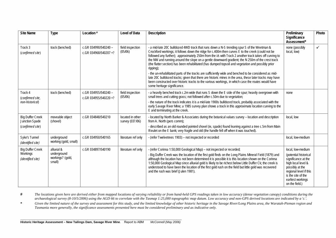
_____________________________________________________________________________________________________ Historic Heritage Assessment – New Tailings Dam, Savage River Mine. Report to ABM McConnell (May 2006)
Site Name Type Location # Level of Data Description Preliminary
Significance Assessment*
Photo
Track 3 (confirmed site)
track (benched) c.GR 034990/540240 – c.GR 034968/540207 +?
field inspection (05/06)
- a mid-late 20C bulldozed 4WD track that runs down a N-S trending spur S of the Weetman & Crockford workings; it follows down the ridge for c.400m then curves E to the creek (could not be followed any further); approximately 250m from the i/s with Track 2 another track takes off curving to the NW and running around the slope on a gentle downward gradient; the N 250m of the crest track (the flatter section) has been rehabilitated (has dumped topsoil and vegetation and possibly prior ripping); - the un-rehabilitated parts of the tracks are sufficiently wide and benched to be considered as mid-late 20C bulldozed tracks; given that there are historic mines in the area, these later tracks may have been constructed over historic tracks to the various workings, in which case the routes would have some heritage significance.
none (possibly local, low)
Track 4 (confirmed site, non-historical)
track (benched) c.GR 034955/540240 – c.GR 034955/540220 +?
field inspection (05/06)
- a heavily benched track c.2m wide that runs S down the E side of the spur; heavily overgrown with small trees and cutting grass; not followed after c.50m due to vegetation; - the nature of the track indicates it is a mid-late 1900s bulldozed track, probably associated with the early Savage River Mine; a 1985 survey plan shows a track in this approximate location curving to the E and terminating at the creek.
none
Big Duffer Creek Junction Spade (confirmed site)
moveable object (shovel)
c.GR 034848/540210 located in other survey (03?/06)
- located by North Barker & Associates during the botanical values survey – location and description from A. North (pers comm); - described as an old rounded pointed shovel (ie, spade) found leaning against a tree c.5m from Main Rivulet on the E bank; very fragile and old (the handle fell off when it was touched).
local, low
Syke's Tunnel (identified site)
underground working (gold, small)
c.GR 034950/540165 literature ref only - (refer Twelvetrees 1903) – not inspected or recorded local, low-medium
Big Duffer Creek Workings (identified site)
alluvial & underground workings? (gold, small)
c.GR 034897/540190 literature ref only - (refer Corinna 1:50,000 Geological Map) – not inspected or recorded; - Big Duffer Creek was the location of the first gold finds on the Long Plains Mineral Field (1879) and although the location has not been determined it is possible it is this location shown on the Corinna 1:50,000 Geological Map since alluvial gold is likely to be richest below Little Duffer Ck; the creek is understood to have been the location of the first gold rush on the field but little gold was recovered and the rush was brief (Julen 1981).
local, low-medium (potential historical significance at the high local level & possibly at the regional level if this is the site of the earliest workings on the field.)
# The locations given here are derived either from mapped locations of varying reliability or from hand-held GPS readings taken in low accuracy (dense vegetation canopy) conditions during the archaeological survey (8-10/5/2006) using the AGD 66 to correlate with the Tasmap 1:25,000 topographic map datum. Low accuracy and non-GPS derived locations are indicated by a 'c.'.
* Given the limited nature of the survey and assessment for this study, and the limited knowledge of other historic heritage in the Savage River/Long Plains area, the Waratah-Pieman region and Tasmania more generally, the significance assessments presented here must be considered preliminary and as indicative only.

_____________________________________________________________________________________________________ Historic Heritage Assessment – New Tailings Dam, Savage River Mine. Report to ABM McConnell (May 2006)
Appendices

_____________________________________________________________________________________________________ Historic Heritage Assessment – New Tailings Dam, Savage River Mine. Report to ABM McConnell (May 2006)

_____________________________________________________________________________________________________ Historic Heritage Assessment – New Tailings Dam, Savage River Mine. Report to ABM McConnell (May 2006)
Appendix 1
PROJECT BRIEF

_____________________________________________________________________________________________________ Historic Heritage Assessment – New Tailings Dam, Savage River Mine. Report to ABM McConnell (May 2006)

_____________________________________________________________________________________________________ Historic Heritage Assessment – New Tailings Dam, Savage River Mine. Report to ABM McConnell (May 2006)
Brief for non Aboriginal Heritage Survey and Assessment BACKGROUND Australian Bulk Minerals (ABM) is carrying out a Bankable Feasibility Study into the prospect of a significant cutback for its North Pit at Savage River. This will require an amendment to its environmental licence (EPN) and its Environmental Management Plan (EMP). As the pit cutback will provide 10 – 15 yeas worth of ore a new tailings dam will be required. Consequently, the previously undisturbed (by ABM) area will need aboriginal and “European” cultural heritage surveys prior to applying for the EMP amendment. ABM has operated the Savage River mine and associated processing facilities since 1997. Scope of Works The scope of the “European” cultural survey and assessment shall include: ♦ Regular liaison and progress review with Caloundra Environmental for an on behalf of ABM. ♦ an inventory survey of historic heritage features contained within the study area, including a
plan identifying the location of the features; ♦ an overall statement of significance for the study area which identifies any individual
significant features. Study Area The study area is defined as:
• The area encompassed by potential new tailings dam locations as indicated in the attached marked up aerial photo and diagram. (figures one & two) and in the attached file “Future Tailings Dam Strategy” Figure 5.
• The area is heavily forested with extremely steep aspect. Access is difficult. Travel along the Main Creek bed from the north is expected to be the best method for accessing the study area.
• Copies of the map are available in DTM and STRING files and are currently accessed at the mine in Surpac.
Outcomes The survey report should identify potential effects of the project, including the development of infrastructure directly related to the project, on non-Aboriginal cultural heritage sites and areas including:
• Declared World Heritage Area properties and values. • Any places listed on the National Heritage List (and interim list) and values. • Any places listed on the Tasmanian Heritage Register (maintained by the Tasmanian
Heritage Council), including consideration of cultural landscapes. • Any places on the Tasmanian Historic Places lnventory (maintained by the Tasmanian
Heritage Office). • Waratah Wynyard Local government planning scheme heritage schedules. • Any other places of heritage significance.
It should identify recommended measures to avoid or mitigate any potential adverse effects on cultural heritage sites and assess the overall effects of the project on cultural heritage sites following implementation of the proposed avoidance and mitigation measures. The cultural heritage surveys must comply with the requirements of the Aboriginal and Historic Cultural Heritage Survey and Recording Standards Consultancy Brief and the Guidance for the Production of Cultural Heritage Survey Reports prepared by the Tasmanian Heritage Office.

_____________________________________________________________________________________________________ Historic Heritage Assessment – New Tailings Dam, Savage River Mine. Report to ABM McConnell (May 2006)
Reporting A report will be provided in electronic format as well as hard copy (colour) including: The cultural heritage report and management recommendations must comply with the requirements of the Aboriginal and Historic Cultural Heritage Survey and Recording Standards Consultancy Brief and the Guidance for the Production of Cultural Heritage Survey Reports prepared by the Tasmanian Heritage Office. Site survey to be completed by 31 January 2006 (brief not provided until March 2006) Provision of a draft report by 28 February 2006 (brief not provided until March 2006). Four copies of a final report incorporating management recommendations shall be provided to ABM as well as an electronic copy on CD Rom or preferably via e mail (in a format compatible with Office 2003) to Caloundra Environmental by 31 March 2006 (date altered to early June 2006). Please liaise with Tony Ferguson regarding anticipated arrival and work on site as well as communication with key stakeholders. Considerations A quotation shall be provided to: Tony Ferguson Australian Bulk Minerals 60 Wilmot Street Burnie Ph Direct 03 6432 3377 Fx 033462 3399 E mail - [email protected] And a copy to: Stephen Kent Caloundra Environmental Ph 07 5439 7877 Fx 07 5439 7868 Mobile 0417 574 799 E mail – [email protected] A works order will be issued prior to commencement of work.

_____________________________________________________________________________________________________ Historic Heritage Assessment – New Tailings Dam, Savage River Mine. Report to ABM McConnell (May 2006)
Figure one Prospective Tailings dam site
Figure Two Pictorial representation of study area

_____________________________________________________________________________________________________ Historic Heritage Assessment – New Tailings Dam, Savage River Mine. Report to ABM McConnell (May 2006)

_____________________________________________________________________________________________________ Historic Heritage Assessment – New Tailings Dam, Savage River Mine. Report to ABM McConnell (May 2006)
Appendix 2
HERITAGE SITE DOCUMENTATION

_____________________________________________________________________________________________________ Historic Heritage Assessment – New Tailings Dam, Savage River Mine. Report to ABM McConnell (May 2006)

Datasheet: May 2006: Anne D. McConnell GPO Box 234, Hobart, Tasmania, 7001; ph 03 6239 1494; [email protected]
SITE DATA SHEET: SMITH'S (OBSIDIAN) MINE p 1
see page 3 for photos
Heritage Listings/Status - None identified
Site Type/Function: Type of site: Mining (alluvial gold workings)
Present use: abandoned Site Location & Owner Information: Mapsheets : Savage River 1:25,000 (3440) mapsheet
Location – Townsends Creek, Savage River GR: c.035008/540320 - c.035010/540335
Owner/Manager – Australian Bulk Minerals (in Mining Lease Area).
Historical Information: The site is interpreted as being Smiths Workings on the basis that the location is marked as 'Obsidian (Smiths)' on the Corinna 1:50,000 geological map and the location conforms with the descriptions in the literature (Julen 1981). There is some possibility that the two adits are the Frenchmans and Frenchmans East tunnels mapped by Twelvetrees (1903) given their arrangement, but Twelvetrees (1903) map shows them some 150m to the S and the accuracy of other map details suggest his locations would not be in such great error. This was the site of the beginning of the second rush on the Long Plains Mineral Field (1882) with gold being discovered by Tom Smith & Harry Howard (Julen 1981). According to Julen (1981) Tom Smith & Harry Howard found coarse gold in rich concentrations in this creek in late 1881. They worked the creek for 2 months and recovered some 450 ounces of gold. Julen also comments that Smith and his partner obtained 120 ounces of gold from a piece of ground 6m x 3m at the junction of Smiths Creek and Townsends Creek (ie, the location of Smiths Workings). According to newspaper reports (Julen 1981, 19) in March 1882 men were leaving the Mt Bischoff mines 'daily' for the Longs Plains rush at Smiths Creek and 'Smiths party had worked out about 30 chains of the creek twice over, others are now working the same ground over again and are making about 2 a day, and by the beginning of July several men were 'engaged working Smiths Creek, a portion of which has been worked six times over and is still paying good wages'. Julen notes that the best gold was found in the slate crevices in the creek beds. Julen (1981, 18) comments that "the creek which was known as Smiths Creek (now named Obsidian Creek on modern maps) [in fact now named Townsends Ck] was one of the richest on the West Coast". Twelvetrees (1903, 4) comment is that "Smiths Creek was the richest on the field".
Site Description & Setting The site is a complex of small scale mining features on both sides of the current Townsends Ck (formerly Smiths Ck) between the first tributary creek to the north (formerly Townsends Ck) and the next creekline/gully to the west (& also on the north side). The north bank has an area of alluvial workings extending up a creek line. The drainage is disturbed and the whole length of gully form Townsends Ck up c.70m has possibly been worked, but the obvious evidence - washed quartz cobble mounds, 1 short narrow trench and 2 exploration pits – were only noted from c.30-40m from Townsends Ck to c.70m distant. A benched track runs above it on the west side c.15 m form the workings, but is thought to be a modern bulldozed track. On the south bank, which is inside a bend in Townsends Creek and has slightly less steep slopes than the adjacent parts of the valley, has a costean to the W which runs c.40-50m up the slope and is forked at the top and other associated ground disturbance (but no clear features) approximately opposite the worked gully. There is an adit and associated mullock heap about 4-5m above the creek and c.20m to the east of the costean. The adit, presumably an exploratory drive, is very small (partly buried?) and cut into a vertical cut back face c.4-5m high. Some 50-80m upstream and also on the south bank of Townsends Creek is a second adit. The adit, presumably an exploratory drive, is very small (partly buried?), about 3m above the creek and cut into a vertical cut back face c.3m high and has a small talus of debris on the ground in front.
(See photos)

Datasheet: May 2006: Anne D. McConnell GPO Box 234, Hobart, Tasmania, 7001; ph 03 6239 1494; [email protected]
SITE DATA SHEET: SMITH'S (OBSIDIAN) MINE p 2 Cultural Significance: This Study (preliminary assessment only) – probable medium – high local cultural (historic heritage) significance, with possibly some regional level significance. Assessed as having mainly historical significance as the first really productive diggings on the Long Plains field, as the site of the second gold rush on the field and as being a rich location. The site is also considered to have local significance as evidence of the workings and ability to demonstrate a typical small scale alluvial mine of the region & period (reduced by reworking) that was recovering gold from the creek beds. The site may also have some regional significance if the claims that the workings were among the richest in the region are correct.
Management Advice/Recommendations: Should be retained undisturbed if possible. Where there is a genuine and major economic imperative that will result in the disturbance or destruction of the site, then
the site should be fully recorded prior to disturbance. Report References : Corinna Geological Map 1:50,000 (Tasmanian Mines Department, MRT, 1991). McConnell, A. 2006 (May) Historic Heritage Assessment – New Tailings Dam, Savage River Mine, Northwest Tasmania. Report prepared for Australian Bulk Minerals, Burnie, Tasmania.
Site Plan (sketch) N Data by: Anne McConnell Date of Field Inspection: 8-10/5/2006
SCALE approximate

Datasheet: May 2006: Anne D. McConnell GPO Box 234, Hobart, Tasmania, 7001; ph 03 6239 1494; [email protected]
SITE DATA SHEET: SMITH'S (OBSIDIAN) MINE p 3 Photographs
1. View (S) of eastern adit on south bank of Townsends Ck (person is standing to LHS of the adit at the top of a short talus slope).
2. View (S) western adit opposite worked gully and on the south bank of Townsends Ck. Adit can be seen at the base of the vertical headwall and the upslope end of the mullock heap is seen in the RHS foreground.

Datasheet: May 2006: Anne D. McConnell GPO Box 234, Hobart, Tasmania, 7001; ph 03 6239 1494; [email protected]

Datasheet: May 2006: Anne D. McConnell GPO Box 234, Hobart, Tasmania, 7001; ph 03 6239 1494; [email protected]
SITE DATA SHEET: UNNAMED WORKINGS 1 p 1
Heritage Listings/Status - None identified
Site Type/Function: Type of site: Mining (alluvial gold workings)
Present use: abandoned Site Location & Owner Information: Mapsheets : Savage River 1:25,000 (3440) mapsheet
Location – Main Rivulet at Obsidian Ck confluence, Savage River GR: c.034975/540305
Owner/Manager – Australian Bulk Minerals (in Mining Lease Area).
N
Plan of workings (scale approximate)
Historical Information: This site is interpreted as the unnamed historical alluvial gold workings shown in this approximate location on the Corinna geological map. There is no historical information for this workings, but it is likely to date to the main phase of alluvial working in the locality which is 1882 – 1890s. The site is not shown on the map in Twelvetrees (1903), but this map focuses on the underground workings in the area and does not show the location of any alluvial workings.
Site Description & Setting The workings comprise and an area of disturbed ground on the relatively flat E bank of Main Rivulet from just above the junction with Obsidian/Grays Ck. The area of working is c.10m wide by c.30-50m long and it extends form c.5m form Main Rivulet to c.20m form Main Rivulet. The disturbance comprises irregular pits and mounds of earth with one large excavated area in the north. The north end has the most clear workings and these terminate abruptly as Main Rivulet swings east at a relatively steep spur ridge.
Cultural Significance: This Study (preliminary assessment only) – probable low local cultural (historic heritage) significance.
Management Advice/Recommendations: No recommendation is made. Report References : Corinna Geological Map 1:50,000 (Tasmanian Mines Department, MRT, 1991). McConnell, A. 2006 (May) Historic Heritage Assessment – New Tailings Dam, Savage River Mine, Northwest Tasmania. Report prepared for Australian Bulk Minerals, Burnie, Tasmania.
Data by: Anne McConnell Date of Field Inspection: 8-10/5/2006

Datasheet: May 2006: Anne D. McConnell GPO Box 234, Hobart, Tasmania, 7001; ph 03 6239 1494; [email protected]

Datasheet: May 2006: Anne D. McConnell GPO Box 234, Hobart, Tasmania, 7001; ph 03 6239 1494; [email protected]
SITE DATA SHEET: GOLDEN RIDGE NORTH WORKINGS p 1 (also WEETMAN & CROCKFORD MINE)
Heritage Listings/Status - None identified
Site Type/Function: Type of site: Mining (alluvial & underground gold workings)
Present use: abandoned Site Location & Owner Information: Mapsheets : Savage River 1:25,000 (3440) mapsheet
Location – Between Grays Ck & Obsidian Ck, Savage River GR: c.0349844/5402456 - c.0349869/5402597 + (GPS McConnell 2006)
Owner/Manager – Australian Bulk Minerals (in Mining Lease Area). (Photo – west end of exploratory tunnel through ridge)
Historical Information: This site is part of the Golden Ridge mine workings documented by Smith (1897), Twelvetrees (1903), Nye (1931) & Julen (1981). The site is a complex with various names and lessees and was worked by various companies over time, but appears to be most commonly known as the Weetman and Crockford Mine. It is understood to have been active at some level from c.1883 to 1922, although the activity is understood to have been intermittent. According to Twelvetrees (1903) the first gold at Golden Ridge was discovered at/near this mine site in c.1883 by Weetman & Crockford who were carrying out surface prospecting. The area was worked alluvial initially, but at the end of 1884 Weetman & Crockford found the first gold bearing vein. Underground working were soon developed by Weetman & Crockford and the site is understood to have operated as an underground mine from 1885 to 1922. Twelvetrees (1903, 5-6) contains detailed accounts of the discoveries and early workings by Messers Weetman & Crockford themselves. By 1903 lease was in the name of Gill, during 1917 – 1920 was being operated by Shore's Surprise GM Co. and during 1920 – 1922 was being operated by Shores Success GM Co. There appear to be no further records of it being worked after 1922 (Twelvetrees 1903, Nye 1931). Companies who were involved in the gold mining at the site include the Weetman & Crockford, GM Co., Long Plains GM Co., Shore's Surprise GM Co., & Shores Success GM Co. (Twelvetrees 1903, Nye 1931). Twelvetrees (1903) described the mine as the only successful underground workings in the Golden Ridge area of the Long Plains Field. Julen (1981, 25-26) notes that overall a comparatively small amount of gold was found at Golden Ridge in the underground workings, but that the ridge yielded many nuggets from at or close to the surface and also crystalline gold for which the ridge was famous. He notes individual crystals recovered are reported to be as large as 6-7mm in length. In 1897 the workings are known to have included Big Tunnel (No.2 level; 400' in 1987)1, Thureau's Tunnel (No 3 level; 1,000 in 1897), a connecting winze and 2 related shafts, No 5 Tunnel, Jarman's Tunnel (250' in 1903), several (other) short adits, an underlay drive, a major mullock heap outside the No.1 level tunnels, a water race, various connecting walking tracks, and other exploratory surface trenches. The actual N-S spur on which these working occur is labelled 'Golden Ridge'. It is also likely that there were camps and/or huts in or near the site area. Support for this comes from (Twelvetrees 1903, 8) who comments that Thureau's tunnel is 'on the west side of the hill [ridge] about 100 feet below the huts [ie, probably on the Golden Ridge crest to the east of the tunnel]" and who also mentions Mr F. Batty's (a prospector) house on the Reward claims which were part of the Weetman & Crockford Mine lease area. No more precise locations are given. The suite of workings historically may have included O'Briens Tunnel, Rileys Tunnel and Falls Tunnel to the north, but because the relationship is not confidently known and these tunnels are treated as separate sites.
( 1. Note: there is some discrepancy between the tunnel lengths and level numbers reported in Smith (1897) and Twelvetrees (1903) that cannot be accounted for by expansion over time (as Twelvetrees 1903 lengths are less than those given by Smith in 1897).

Datasheet: May 2006: Anne D. McConnell GPO Box 234, Hobart, Tasmania, 7001; ph 03 6239 1494; [email protected]
SITE DATA SHEET: GOLDEN RIDGE NORTH WORKINGS p 2 (also WEETMAN & CROCKFORD MINE) Site Description & Setting Only the main ridge was inspected in May 2006. The site has had recent visitation and many of the various feature have been marked with flagging tape and it was the obvious features in this area that were inspected. The Big, Thureau and Jarmans Tunnel areas were not inspected. The site appears from the inspection to be a complex of historic mining related features located across a distinctive broad flat ridge and down the west side part way to Grays Creek. A number of the features shown on Smith's (1897) map were re-located including, the western exploratory drive, the No.1 and 1 A level adits and associated mullock heap, the minor adit upslope to the N, the exploratory drive through the ridge and cross cut to surface, the water race, the exploratory trench at the south end of the site, and possibly the track to the east end of the through tunnel. Additional features that were located were a track that appears to follow the line of the winze on the surface and an associated trench, a small number of other costeans on the ridge, a part of a large circular steel artefact on the north edge of the mullock heap, and a possible hut site (a low mound of stone and earth (chimney base?) and 2 section of narrow metal pipe and one strip of flat iron on a relatively flat and open area of the ridge crest on the southeast side. The field inspection revealed that Smiths (1897) is very accurate and has shown most of the features in the area. One interesting feature of the tunnel adits and the exploratory tunnel through the ridge is very long approaches (trenches), in particular on the north side of the exploratory through tunnel which is some 35-50 feet long and has a bend in it.
Apart from some recent clearing of vegetation (by hand) around features and the flagging tape and recent foot pads, the site is otherwise undisturbed and appears to be essentially as it was in 1879.
(See photos)
Cultural Significance: This Study (preliminary assessment only) – probable local high cultural (historic heritage) significance, and possible low-medium regional level significance. This site is considered to be more significant than most of the other sites in the area given its complexity and its high degree of integrity, as well as for its historical importance (ie, as the location of the first find on the Golden Ridge, as the first and most significant Golden Ridge mines (ie, a major producer and long lived)), and as a rare underground mine on the Long Plains field. It is therefore considered to have high local level significance. It may also be of significance at a regional level as a rare underground gold mine in the region, and as the key mine on the Golden Ridge which was well known for its relatively high gold productions and the particular nature of the gold and its occurrence.
Management Advice/Recommendations: Should be considered for long term conservation as an extremely important site on the historic Long Plains Mineral
Field. Should be retained undisturbed if possible given its significance and as an intact, high integrity mine. Where there is a genuine and major economic imperative that may lead to disturbance or destruction of the site, then the
site should be fully recorded and re-assessed prior to any disturbance. Report References : Corinna Geological Map 1:50,000 (Tasmanian Mines Department, MRT, 1991). McConnell, A. 2006 (May) Historic Heritage Assessment – New Tailings Dam, Savage River Mine, Northwest Tasmania. Report prepared for Australian Bulk Minerals, Burnie, Tasmania. Nye, P.B. 1931 'Shore's Surprise Mine, Long Plains', Government Geologist Report – Mineral Resources Tasmania UR 1931/49. Smith, J. Harcourt 1897 Report on the Mineral District between Corinna and Waratah. Secretary for Mines Report, 1896-97 (Plan of the 'Long Plains Gold Mining Company Underground Workings' – J. Harcourt Smith, 25/7/1897). Twelvetrees, W.H. 1903 Report on Mineral Fields between Waratah and Long Plain. Tasmanian Department of Mines, Old Series Report 207, Tasmania.
Data by: Anne McConnell Date of Field Inspection: 8-10/5/2006

Datasheet: May 2006: Anne D. McConnell GPO Box 234, Hobart, Tasmania, 7001; ph 03 6239 1494; [email protected]
SITE DATA SHEET: GOLDEN RIDGE NORTH WORKINGS p 3 (also WEETMAN & CROCKFORD MINE) Photographs
1. Approach and adit to the west end of the exploratory throuhg tunnel (view E).
2. Cross cut (L-R) in exploratory through tunnel (view E along through tunnel).
3. Eastern end of exploratory through tunnel showing bend and bench in floor (view E).
4. Approach to the eastern end of exploratory through tunnel (view NE).

Datasheet: May 2006: Anne D. McConnell GPO Box 234, Hobart, Tasmania, 7001; ph 03 6239 1494; [email protected]
SITE DATA SHEET: GOLDEN RIDGE NORTH WORKINGS p 4 (also WEETMAN & CROCKFORD MINE) Photographs - continued
5. Fragmented metal artefact on north edge of mullock heap.
6. Track with trench on uphill edge that runs along the line of the winze below; connects the ridge crest and mullock heap and is possibly the 'walking track' shown on Smith's (1897) map (view SE).
2. The possible hut site on ridge crest; photo shows a low mound and a strip of flat metal (view NE).
2. The possible hut site on ridge crest; photo shows two metal pipes in the open flat area immediately north of the low mound; there are cross drains out of sight on the edge of the flat area on RHS (view SE).

Datasheet: May 2006: Anne D. McConnell GPO Box 234, Hobart, Tasmania, 7001; ph 03 6239 1494; [email protected]
SITE DATA SHEET: GOLDEN RIDGE NORTH WORKINGS p 5 (also WEETMAN & CROCKFORD MINE)
Plans – Plan of greater Golden Ridge Workings in Twelvetrees (1903)

Datasheet: May 2006: Anne D. McConnell GPO Box 234, Hobart, Tasmania, 7001; ph 03 6239 1494; [email protected]
SITE DATA SHEET: GOLDEN RIDGE NORTH WORKINGS p 4 (also WEETMAN & CROCKFORD MINE)
Plans – Plan of Weetman & Crockford Mine by J. Harcourt Smith (1897) (copy of map supplied by Australian Bulk Minerals, Savage River).

Datasheet: May 2006: Anne D. McConnell GPO Box 234, Hobart, Tasmania, 7001; ph 03 6239 1494; [email protected]
SITE DATA SHEET: GOLDEN RIDGE TRACK p 1
no photographs
Heritage Listings/Status - None identified
Site Type/Function: Type of site: Mining (gold) (track)
Present use: abandoned Site Location & Owner Information: Mapsheets : Savage River 1:25,000 (3440) mapsheet
Location – Ridge between Savage River townsite & Main Rivulet, Savage River GR: c. c.034986/540246 +
Owner/Manager – Australian Bulk Minerals (in Mining Lease Area).
Historical Information: This site is interpreted as a section of the original access track to the Golden Ridge workings from the main Waratah–Corinna track to the east (crossed approximately through the site of the former Savage River township) as the access track is shown in this approximate location on Smith's (1997) map of the workings.
Site Description & Setting A short section (c.15-20m long) of narrow (c.1.5m wide)) benched dirt track at the SE end of the Weetman & Crockford workings. The section was not followed to the east, but may continue around the side of the ridge. Smiths (897) map shows the track curving sharply to the SW west of the located section, and although the track was not followed to the west, it is probable that it has been bulldozed over by the present modern access track.
Cultural Significance: This Study (preliminary assessment only) – probable local low-medium cultural (historic heritage) significance.
Management Advice/Recommendations: Should be retained undisturbed if possible as a related/associated element of the Golden Ridge mines. Where there is a genuine and major economic imperative that will result in the disturbance or destruction of the site, then
the full extent of the site should be fully recorded prior to disturbance. Report References : McConnell, A. 2006 (May) Historic Heritage Assessment – New Tailings Dam, Savage River Mine, Northwest Tasmania. Report prepared for Australian Bulk Minerals, Burnie, Tasmania. Smith, J. Harcourt 1897 Report on the Mineral District between Corinna and Waratah. Secretary for Mines Report, 1896-97 (Plan of the 'Long Plains Gold Mining Company Underground Workings' – J. Harcourt Smith, 25/7/1897). Data by: Anne McConnell Date of Field Inspection: 8-10/5/2006

Datasheet: May 2006: Anne D. McConnell GPO Box 234, Hobart, Tasmania, 7001; ph 03 6239 1494; [email protected]

DEVELOPMENT PROPOSAL AND ENVIRONMENTAL MANAGEMENT PLAN South Deposit Tailings Storage Facility APPENDIX P Assessment of Acid Rock Drainage Neutralisation Using Tailings March 2013
An Assessment of Acid Rock Drainage Neutralisation Using Tailings from the Savage River Mine, Tasmania
Aquatic Science
Prepared for
Grange Resources (Tasmania) Pty Ltd
August 2009

SAVAGE RIVER MINE
Assessment of ARD Neutralisation Using Tailings Page...i
Contents Page
1.0 Introduction .................................................................................................................. 1
2.0 Background Information .................................................................................................. 3
2.1 Tailings Dam Acid Loads ......................................................................................... 3
2.2 Main Creek Acid Loads ........................................................................................... 4
2.3 Tailings Production and Density ............................................................................. 5
3.0 Testing Program ............................................................................................................... 6
3.1 Sample Collection ................................................................................................... 6
3.1.1 Old Tailings Dam Seepage ......................................................................... 6
3.1.2 B‐Dump Complex Drainage ....................................................................... 6
3.1.3 Tailings Composite .................................................................................... 7
3.2 Field Testing Procedures ........................................................................................ 7
3.2.1 Ferrous Iron Determination ...................................................................... 7
3.2.2 Acidity Titration ........................................................................................ 7
3.3 Analytical Procedures ............................................................................................. 8
3.3.1 Mixing Tests .............................................................................................. 8
3.3.1.1 Mixing Test Procedure .................................................................. 8
3.3.1.2 Mixing Test Parameters and Trial Test Results ............................. 9
3.3.2 Geochemical Characterisation of Tailings ................................................ 10
3.3.2.1 Static Geochemical Testing ........................................................... 11
3.3.2.2 Leach Column Testing ................................................................... 14
4.0 Tailings Geochemistry ...................................................................................................... 17
4.1 pH and Salinity ....................................................................................................... 17
4.2 Acid Forming Characteristics .................................................................................. 17
4.3 Metal Enrichment and Solubility ............................................................................ 17
5.0 Mixing Test Results ........................................................................................................... 18
5.1 Mixing test quantities and field measurements .................................................... 18
5.2 Sludge Density Analysis .......................................................................................... 18
5.3 Water Quality ......................................................................................................... 19
6.0 Recommendations ........................................................................................................... 23
6.1 Tailings Management ............................................................................................. 23
6.2 Operational Performance Monitoring ................................................................... 23
6.3 Future Testing Requirements ................................................................................. 23
7.0 References .................................................................................................................. 24
APPENDIX A: Mixing Test Results
APPENDIX B: Multi‐Element Analysis Results
APPENDIX C: Preliminary Leach Column Test Result

SAVAGE RIVER MINE
Assessment of ARD Neutralisation Using Tailings Page...ii
Tables Page
1: Main Creek above Savage River acidity loads 1998 and 1999 ......................................... 4 2: Summary test‐work undertaken with measurements recorded in the field
updated with laboratory measurements ......................................................................... 18 3: Data and analysis relating to sludge densities ................................................................. 19 4: Water quality results of ARD sources and decanted water from measuring
cylinders after mixing ....................................................................................................... 20 5: Water volumes, calculated initial concentrations, concentrations measured
after mixing and the percentage removal of contaminants. ........................................... 21 6: Calculated initial concentrations, concentrations measured after mixing and
the percentage increase in parameters that increased. .................................................. 22
Figures Page
1: Acidity over time at the Main Creek above Savage River sample site ............................. 4 2: MCTD Historical Tailings Density (Source: GHD 2008) ..................................................... 5 3: Location of the B‐Dump below pilot plant sample site .................................................... 7 4: Bench top axial flow mixer used for mixing trials ............................................................ 9 5: Leach Column Schematic.................................................................................................. 15

SAVAGE RIVER MINE
Assessment of ARD Neutralisation Using Tailings Page...1
1.0 Introduction Grange Resources (Tasmania) Pty Ltd operates the Savage River Mine and in conjunction with the Department of Primary Industries, Parks, Water and Environment (DPIPWE), and Mineral Resources Tasmania (MRT) manages the Savage River Rehabilitation Project (SRRP) to remediate a legacy of ARD at the Savage River Mine. The current tailings management plan at Savage River is to deposit all of the future tailings into the Main Creek Tailings Dam. Based on the historical tailings density of 1.85 t/m3 it has been determined that the Main Creek Tailings Dam will have sufficient capacity to store the future tailings. However, recent surveys have indicated that tailings densities have decreased to between 1.3 and 1.5 t/m3. Based on these densities, it is expected that the Main Creek Tailings Dam will be at capacity by 2017 at which time additional storage will be required. The development of a new Tailings Storage Facility (TSF) near the South Deposit could assist Grange Resources (Tasmania) Pty Ltd and the EPA with environmental benefits, in the form of cost effective neutralisation of legacy ARD. The project involves construction of the following major items in Main Creek: • A new TSF with a “flow through” spillway, • A Flow‐through Waste Rock Dump behind the dam wall, • A Settlement Dam below the dam; and • ARD collection ponds and transfer pipe line. The potential benefits include, not only tailings storage capacity to cater for a proposed mine life to 2028, but introduction of a significant alkalinity load and a viable solution for long‐term treatment of ARD seeps from B‐Dump and the Old Tailings Dam (OTD). In addition a proportion of the historic waste in B Dump would be inundated by the tailings. Grange Resources (Tasmania) Pty Ltd has commissioned Aquatic Science and Geo‐Environmental Management Pty Ltd (GEM) to conduct an assessment of the capacity of the tailings to treat the increased acidity load, mixing requirements and assess the likely changes in tailing geochemistry. The specific objectives of this assessment include: An evaluation of both tailings loads and acid rock drainage loads that would enter a
tailings storage facility in Main Creek. Mixing tests using the above loads to establish whether the tailings will have the
capacity to neutralise the increased acidity that will result from mixing with the ARD from the B‐Dump complex.
The setup methodology for the leach column test‐work. This test‐work will give an indication of time required for the tailings to begin producing acidity after exposure to the atmosphere.

SAVAGE RIVER MINE
Assessment of ARD Neutralisation Using Tailings Page...2
The test‐work has been expanded to concurrently examine whether the neutralisation using tailings impacts on the sludge densities that may be achieved within the tailings storage facilities. This is due to the observation made by Dr Nick Clarke during Mt Lyell test‐work that found that tailings volume can be increased substantially by mixing with ARD. This report provides an assessment of acidity loads that are likely to be encountered with the placement of tailings storage in the Main Creek Valley. This data is then used for the design of mixing tests and preparation of tailings for geochemical test work including leach column tests. The mixing tests undertaken using composite tailings sample collected in early June 2009 are presented with some preliminary observations discussed.

SAVAGE RIVER MINE
Assessment of ARD Neutralisation Using Tailings Page...3
2.0 BackgroundInformation
The neutralisation test‐work is designed to be based on the ARD loads that have been ascertained from field measurements and laboratory analyses. The load data has been collected by the Savage River Rehabilitation Project and GHD. The calculation of loads is discussed in the sections 2.1 Old Tailings Dam Acid Loads and 2.2 Main Creek Acid Loads. The tailings loads used are based on the work by GHD in the document ‘Report for MCTD Tailings 10yr Plan, Tailings Reconciliation & Planning’,(GHD 2008). The calculation of tailings loads are discussed in the Section 2.3 . The neutralisation test‐work has also been based on the premise that the ARD from the Old Tailings Dam wall and the B‐Dump drainage can be mixed by co‐disposal at the point of tailings discharge. This is based on advice received from Grange Resources staff and GHD.
2.1 OldTailingsDamAcidLoads The report ‘Savage River Mines, Main No.1 Tailings Dam Report on Seepage, Draft (Thompson and Brett Pty Ltd 1996), measures the total OTD acidity production from the Old Tailngs Dam Wall (Southern End). This study included a dataset of samples collected from the outflow of ponds that formed when the seeps were isolated from the remainder of the dam by tailings. The flow and acidity concentrations were measured and acidity loads calculated. The samples were collected daily over the period 9th of August 1996 to 6th September 1996. The average acidity load was measured to be 1.62 kg/min CaCO3 equivalent which equates to 2.3 t/day CaCO3 equivalent. The samples in this study were collected toward the end of the West Coast Tasmania wet season. It would be expected that the acidity loads at this time of year would be near their peak. The seasonality of the pollutant loads from the Old Tailings Dam is discussed in some detail in the thesis ‘A hydrogeological and geochemical characterisation of an abandoned tailings dam at Savage River Mine, Tasmania (Hassell 2005). The above acidity load data was collected 13 years ago. It was therefore decided that an acidity load of 2 tonne per day would provide a conservative estimate from this pollutant source. The acidity load from the seeps is therefore calculated to be 730 tonne per year. The first test will therefore be to try and replicate previous performance. The seepage ARD will therefore be mixed with tailings at the ratio of: 730 tonne per year acidity (CaCO3 eq)/2,300,000t tailings or 1/3150 acidity to tailings ratio mass Therefore 1 kg of tailings will require 318mg of acidity. Given that seepage will be flushed out of the seep ponds to a limited extent during wetter periods a safety factor of 50% will be added to this figure. Therefore a dose rate of 500mg (rounded from 477 mg) of acidity per kg of tailings was added in the trials to represent a conservative estimate of winter loads.

SAVAGE RIVER MINE
Assessment of ARD Neutralisation Using Tailings Page...4
2.2MainCreekAcidLoads From Table 1 below it can be seen that the average acidity load from Main Creek averages 1.27t per day. In Figure 1 the acidity load is graphed over time. Table 1 ‐ Main Creek above Savage River acidity loads 1998 and 1999
Acidity Flux (t/Day)
Mean 1.27
90th Percentile 2.22
80th Percentile 1.63
20th Percentile 0.69
10th Percentile 0.62
5th Percentile 0.55
Median 0.88
Sample Number 235
Main Creek above Savage River
Figure 1 ‐ Acidity over time at the Main Creek above Savage River sample site
From the above data a conservative acidity dose into the tailings from B‐Dump seepage would be to use the 90th percentile value of 2.22 tonne per day. This is intended to represent the acidity load during wet periods when greater acidity fluxes are being flushed through the dumps. This corresponds to an annualised load of 810 tonnes per year. Given the tailings output of 2,300,000t this corresponds to an acidity dose 1 tonne of acidity (CaCO3 eq) to every 2840 tonnes of tailings. Therefore for every kg of tailings there will be a dose of 400 (rounded from 352 mg) of acidity (CaCO3 eq).

SAVAGE RIVER MINE
Assessment of ARD Neutralisation Using Tailings Page...5
2.3TailingsProductionandDensity The last reconciliation report “Reconciliation and Future Staged Raising of the MCTD” November 2006 by GHD resulted in an average tailings (dry) density of 1.8t/m3. This was consistent with previous tailings density calculated by reconciliation in 2004 by Thompson & Brett Pty Ltd.
Figure 2 – MCTD Historical Tailings Density (Source: GHD 2008)
From the above graph the tailings production is close to linear between 1998 and mid 2007. From the slope of the graph it can be calculated that the average tailings production during this time is consistently around 2.5Mt per annum. The report quotes that production was around 2.3 tonne per annum. The figure of 2.3Mt per annum has been used as it will provide the more conservative estimate of tailings production. Future tailings production increases are also anticipated.

SAVAGE RIVER MINE
Assessment of ARD Neutralisation Using Tailings Page...6
3.0TestingProgram
3.1SampleCollection Two water samples and one bulk tailings sample were collected for the mixing tests carried out on‐site by Daniel Ray of Aquatic Science from 15 June 2009 to 16 June 2009. The water samples were collected from two of the major acid rock drainage (ARD) sources of the mine; seepage from the Old Tailings Dam (OTD) and drainage from the B‐Dump. The samples collected are considered to be representative of these ARD sources. The bulk tailings sample used for the mixing test was collected at the mill by site personnel over an 8 day period prior to the site visit. 3.1.1 OldTailingsDamSeepage The OTD water sample was collected on 1 April 2009 from a single seepage located in the Southern Wall of the OTD (need to get location information including photo). The water that was sampled was aged so the majority of iron present was in the form of ferric iron. To check that the oxidation to ferric iron had occurred the concentration of ferrous iron was measured on site using the iron 1,10‐Phenanthroline method* (see Section 3.2 ). This field test confirmed that the water sampled only had a low concentration of ferrous iron (< 1 mg/L) indicating that the majority of the iron present was in the form of ferric iron. Field measurements of the aged OTD sample were taken during the site visit (15 June 2009). These measurements confirm that the water is highly acidic with a pH of 2.53 and an electrical conductivity of 3.25 mS/cm. The temperature of the water was 16.3oC An acidity titration was carried out in the field (see Section 3.2 ) to establish the approximate acidity of the water that was sampled. This enabled the mixing ratios of water to tailings to be applied that were similar to the target levels prior to the laboratory results being available. The field acidity titration indicated that this water sample had an acidity of approximately 1170 mg/L CaCO3 eq when titrated to pH 7. 3.1.2 B‐DumpComplexDrainage The B‐Dump water sample was collected on 15th of June 2006 from the V‐ Notch weir below the pond where the Pilot Plant was located. The sample site location is presented in Figure 3. . Field measurements taken at the time of sampling indicate that the sampled water had a pH of 3.41, an electrical conductivity of 2.78 mS/cm and an acidity of approximately 260 mg/L CaCO3 eq titrated to pH 7. At the time of sampling the water level in the v‐notch weir was 200 mm which corresponds to a flow of approximately 24.8 L/sec. It is estimated that flow around the sides of the weir was equivalent to 10% of the flow through the weir. The total flow was therefore estimated to be 27.4 L/sec.

SAVAGE RIVER MINE
Assessment of ARD Neutralisation Using Tailings Page...7
Figure 3 ‐ Location of the B‐Dump below pilot plant sample site.
3.1.3 TailingsComposite The tailings were sampled by Grange Resources staff. Individual samples were collected as slurries from the spigot (valve) at the tailings discharge pumps. Duplicate samples of approximately 1 kg (700 ml) was collected every 4 hrs (approximate) over an 8 day period from the 5th to 13th of June 2009. One of each duplicate sample was then composited into a bulk slurry sample weighing approximately 32 kg. This composited sample was then sub‐sampled for the test‐work as required.
3.2FieldTestingProcedures3.2.1 FerrousIronDetermination Ferrous iron was measured using a LaMotte Smart Spectrophotometer. This is a portable single beam spectrophotometer. The method used was the 1,10‐Phenanthroline method – code 3668‐sc without the use of the reducing reagent. 3.2.2 AcidityTitration The acidity titration was carried out in the field as follows. A 100 ml sample of water was titrated with 0.1M NaOH using a 10 ml syringe. The sample was aerated using an air pump

SAVAGE RIVER MINE
Assessment of ARD Neutralisation Using Tailings Page...8
to ensure that the sample was oxidised and well mixed. The pH end‐point of 7 was measured using a calibrated WTW field pH meter. The titre volume was then used to calculate the acidity. All samples were sent to the Analytical Services Laboratory in Hobart for accurate acidity measurement.
3.3AnalyticalProcedures3.3.1 MixingTests The mixing tests were carried out with a bench top scale axial flow mixer (see Figure 4). The mixer was configured to mix with an impellor within a vessel with three vertical baffles. The impellor speed was adjustable using a variable speed drive. The system was made from equipment used by the Savage River Rehabilitation Project for the laboratory scale pilot trial treating ARD with carbonate materials. The mixing vessel had a maximum capacity of 1500 ml. Axial flow mixing was used for the following reasons:
It is a relatively gentle method of mixing.
If longer mixing times are required, it is a common technology used by the mining industry and can be scaled up as required.
3.3.1.1 MixingTestProcedure Following is the sequence used for the mixing trials:
1. Homogenise composited tailings by vigorous mixing with stainless steel ladle. 2. Immediately ladle a volume of tailings into a measuring cylinder before settlement. 3. Measure and record the volume and weight of the tailings mixture. 4. Transfer the tailings to a mixing vessel. 5. Calculate the approximate dry mass of the tailings assuming a bulk density of 2.44
g/ml (predetermined from sample collected on previous site visit). The calculation used was: Dry tailings mass estimate (g) = (Weight of mixture (g)‐volume of mixture (ml))*2.44(g/ml) (2.44(g/ml) ‐1)
6. Prepare volumes of acid rock drainage (ARD) solution(s) to be added. The volumes required were determined from the field acidity measurement for each ARD sample according to the following calculation: Volume ARD (ml) = Dry tailings mass estimate (g) * Dose required (mg/kg) Field acidity (mg/L CaCO3 eq to pH 7)
7. Mix the sample with the mixer set on the slowest speed possible while ensuring that
the tailings are adequately mixed from the top to the bottom in the mixing vessel. 8. Add prepared volumes of ARD and mix for a predetermined time (30 seconds for all
samples) 9. Decant mixed tailings and ARD solution to a 1 litre measuring cylinder and allow to
settle 10. Measure and record the pH of the solution in measuring cylinder. 11. Allow mixture to settle for 24 hrs. 12. Record tailings volume.

SAVAGE RIVER MINE
Assessment of ARD Neutralisation Using Tailings Page...9
13. Decant supernatant from the settled tailings and transfer to sample containers. Care was taken to sample the full depth range of the supernatant in case stratification had occurred.
14. Transfer the remaining tailings to an open‐mouth container and record the mass of the tailings.
15. Dry the remaining tailings and retain for geochemical testing.
Figure 4 ‐ Bench top axial flow mixer used for mixing trials
3.3.1.2 MixingTestParametersandTrialTestResults The mixing test trials conducted during the site visit were: Neat ‐ tailings sample with no ARD added. OTD Seepage ‐ tailings sample mixed with OTD seepage. The approximate dose rate was 500mg OTD acidity to 1 kg of tailings. This test was carried out in triplicate. OTD Seepage & B‐Dump Drainage ‐ tailings sample mixed with OTD seepage and B‐Dump drainage. The approximate dose rate was 500mg OTD acidity and 400 mg B‐Dump acidity to 1 kg of tailings. This test was carried out in triplicate. A summary of the material characteristics and volumes used for each mixing test trial and the preliminary results are presented in Appendix A.

SAVAGE RIVER MINE
Assessment of ARD Neutralisation Using Tailings Page...10
The trials were undertaken with the replicates for the ‘OTD seepage’ tests alternated with the ‘OTD seepage & B‐Dump drainage’ tests. This order ensured that temporal changes due to different premixing of tailings to ensure homogeneity did not bias a particular treatment. 3.3.2 GeochemicalCharacterisationofTailings In order to obtain the quantity of sample required for the geochemical characterisation testing program the mixing test procedures were re‐run repeatedly and the tailings generated were composited into a single sample for each treatment. The treatment for the 'OTD Seepage only' involved dosing the tailings with a volume of Old Tailings Dam Seepage equating to an acidity dose of 500 mg/kg. Likewise, the treatment for the 'OTD Seepage and B‐Dump Drainage' involved dosing the tailings with a volume of Old Tailings Dam Seepage equating to an acidity dose of 500 mg/kg and a volume of B‐Dump drainage equating to an acidity dose of 400 mg/kg. Following is the sequence used to generate the samples for geochemical testing.
1. Homogenise composited tailings by vigorous mixing with stainless steel ladle. 2. Immediately ladle specified volume of tailings, according to Table 1) into a
measuring cylinder before settlement. 3. Measure and record the volume and weight of the tailings mixture. 4. Transfer the tailings to a mixing vessel. 5. Calculate the approximate dry mass of the tailings assuming a bulk density of 2.44
g/ml (predetermined from sample collected on previous site visit). The calculation used was: Dry tailings mass estimate (g) = (Weight of mixture (g)‐volume of mixture (ml))*2.44(g/ml) (2.44(g/ml) ‐1)
6. Prepare volumes of acid rock drainage (ARD) solutions to be added. The volumes required were determined from the field acidity measurement for each ARD sample according to the following calculation: Volume ARD (ml) = Dry tailings mass estimate (g) * Dose required (mg/kg) Field acidity (mg/L CaCO3 eq to pH 7)
7. Mix the sample with the mixer set on the slowest speed possible while ensuring that
the tailings are adequately mixed from the top to the bottom in the mixing vessel. 8. Add prepared volumes of ARD and mix for a predetermined time (30 seconds for all
samples) 9. Composite sample into a bulk sample.
The ‘Neat’ tailings sample was ladled directly from the composited tailings. The prepared samples were then sent to GEM for geochemical characterisation testing. This testing program included static and leach column testing, discussed below.

SAVAGE RIVER MINE
Assessment of ARD Neutralisation Using Tailings Page...11
3.3.2.1 StaticGeochemicalTesting Acid Forming Characteristic Evaluation A number of test procedures are used to assess the acid forming characteristics of mine waste materials. The most widely used assessment methods are the acid‐base account (ABA) and the net acid generation (NAG) test. These methods are referred to as static procedures because each involves a single measurement in time. Acid‐Base Account The acid‐base account involves laboratory procedures that evaluate the balance between acid generation processes (oxidation of sulphide minerals) and acid neutralising processes (dissolution of alkaline carbonates, displacement of exchangeable bases, and weathering of silicates). The values arising from the acid‐base account are referred to as the maximum potential acidity (MPA) and the acid neutralising capacity (ANC), respectively. The difference between the MPA and ANC value is referred to as the net acid producing potential (NAPP). The MPA is calculated using the total sulphur content of the sample. This calculation assumes that all of the sulphur measured in the sample occurs as pyrite (FeS2) and that the pyrite reacts under oxidising conditions to generate acid according to the following reaction: FeS2 + 15/4 O2 + 7/2 H2O => Fe(OH)
3 + 2 H2SO4 According to this reaction, the MPA of a sample containing 1 %S as pyrite would be 30.6 kilograms of H2SO4 per tonne of material (i.e. kg H2SO4/t). Hence the MPA of a sample is calculated from the total sulphur content using the following formula: MPA (kg H2SO4/t) = (Total %S) x 30.6 The use of the total sulphur assay to estimate the MPA is a conservative approach because some sulphur may occur in forms other than pyrite. Sulphate‐sulphur and native sulphur, for example, are non‐acid generating sulphur forms. Also, some sulphur may occur as other metal sulphides (e.g. covellite, chalcocite, sphalerite, galena) that yield less acidity than pyrite when oxidised. The acid formed from pyrite oxidation will to some extent react with acid neutralising minerals contained within the sample. This inherent acid neutralisation is quantified in terms of the ANC and is commonly determined using the Modified Sobek method. This method involves the addition of a known amount of standardised hydrochloric acid (HCl) to an accurately weighed sample, allowing the sample time to react (with heating), then back titrating the mixture with standardised sodium hydroxide (NaOH) to determine the amount of unreacted HCl. The amount of acid consumed by reaction with the sample is then calculated and expressed in the same units as the MPA (kg H2SO4/t). The net acid producing potential (NAPP) is a theoretical calculation commonly used to indicate if a material has the potential to produce acid. It represents the balance between the capacity of a sample to generate acid (MPA) and its capacity to neutralise acid (ANC). The NAPP is also expressed in units of kg H2SO4/t and is calculated as follows:
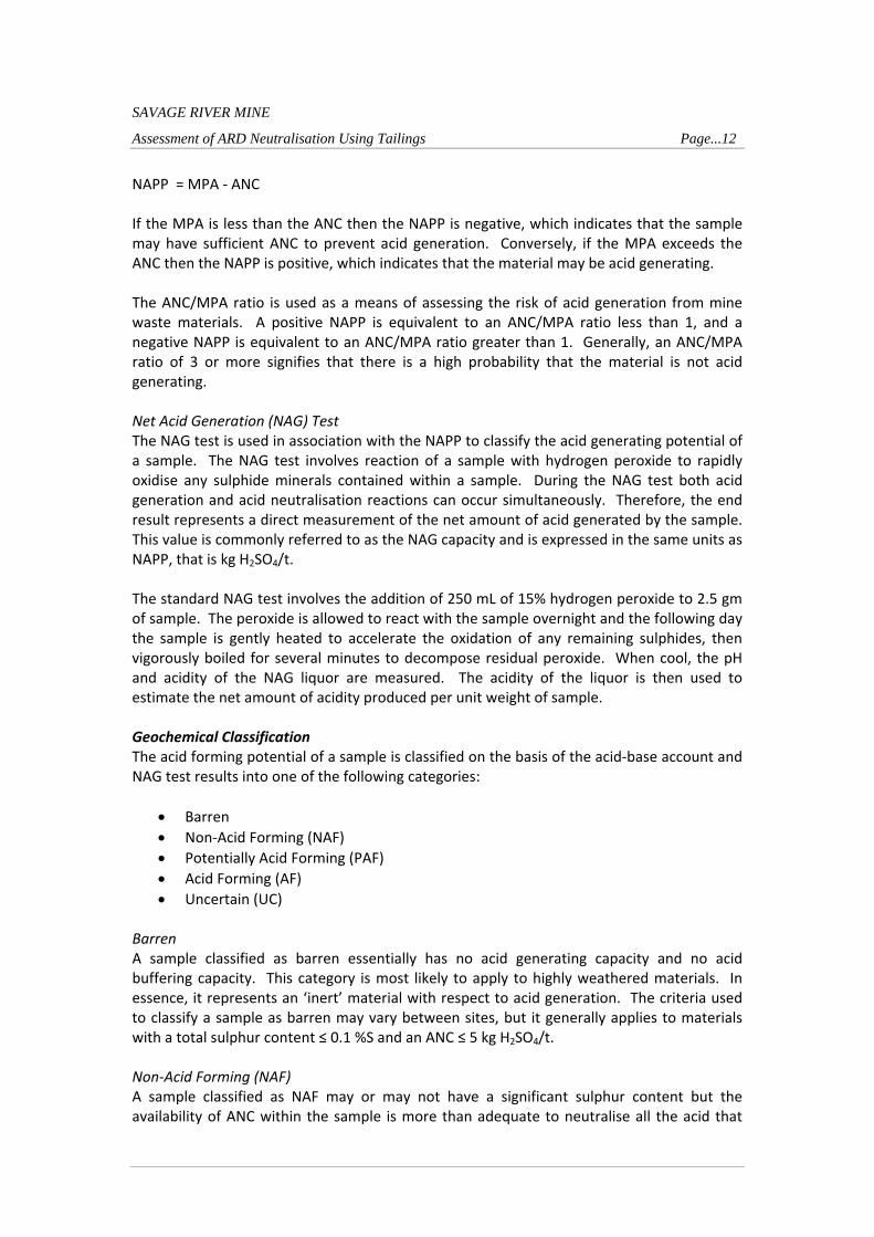
SAVAGE RIVER MINE
Assessment of ARD Neutralisation Using Tailings Page...12
NAPP = MPA ‐ ANC If the MPA is less than the ANC then the NAPP is negative, which indicates that the sample may have sufficient ANC to prevent acid generation. Conversely, if the MPA exceeds the ANC then the NAPP is positive, which indicates that the material may be acid generating. The ANC/MPA ratio is used as a means of assessing the risk of acid generation from mine waste materials. A positive NAPP is equivalent to an ANC/MPA ratio less than 1, and a negative NAPP is equivalent to an ANC/MPA ratio greater than 1. Generally, an ANC/MPA ratio of 3 or more signifies that there is a high probability that the material is not acid generating. Net Acid Generation (NAG) Test The NAG test is used in association with the NAPP to classify the acid generating potential of a sample. The NAG test involves reaction of a sample with hydrogen peroxide to rapidly oxidise any sulphide minerals contained within a sample. During the NAG test both acid generation and acid neutralisation reactions can occur simultaneously. Therefore, the end result represents a direct measurement of the net amount of acid generated by the sample. This value is commonly referred to as the NAG capacity and is expressed in the same units as NAPP, that is kg H2SO4/t. The standard NAG test involves the addition of 250 mL of 15% hydrogen peroxide to 2.5 gm of sample. The peroxide is allowed to react with the sample overnight and the following day the sample is gently heated to accelerate the oxidation of any remaining sulphides, then vigorously boiled for several minutes to decompose residual peroxide. When cool, the pH and acidity of the NAG liquor are measured. The acidity of the liquor is then used to estimate the net amount of acidity produced per unit weight of sample. Geochemical Classification The acid forming potential of a sample is classified on the basis of the acid‐base account and NAG test results into one of the following categories:
Barren
Non‐Acid Forming (NAF)
Potentially Acid Forming (PAF)
Acid Forming (AF)
Uncertain (UC) Barren A sample classified as barren essentially has no acid generating capacity and no acid buffering capacity. This category is most likely to apply to highly weathered materials. In essence, it represents an ‘inert’ material with respect to acid generation. The criteria used to classify a sample as barren may vary between sites, but it generally applies to materials with a total sulphur content ≤ 0.1 %S and an ANC ≤ 5 kg H2SO4/t. Non‐Acid Forming (NAF) A sample classified as NAF may or may not have a significant sulphur content but the availability of ANC within the sample is more than adequate to neutralise all the acid that

SAVAGE RIVER MINE
Assessment of ARD Neutralisation Using Tailings Page...13
theoretically could be produced by any contained sulphide minerals. As such, material classified as NAF is considered unlikely to be a source of acidic drainage. A sample is usually defined as NAF when it has a negative NAPP and a final NAGpH ≥ 4.5. Potentially Acid Forming (PAF) A sample classified as PAF always has a significant sulphur content, the acid generating potential of which exceeds the inherent acid neutralising capacity of the material. This means there is a high risk that such a material, even if pH circum‐neutral when freshly mined or processed, could oxidise and generate acidic drainage if exposed to atmospheric conditions. A sample is usually defined as PAF when it has a positive NAPP and a final NAGpH < 4.5. Acid Forming (AF) A sample classified as AF has the same characteristics as the PAF samples however these samples also have an existing pH of less than 4.5. This indicates that acid conditions have already been developed, confirming the acid forming nature of the sample. Uncertain (UC) An uncertain classification is used when there is an apparent conflict between the NAPP and NAG results (i.e. when the NAPP is positive and NAGpH > 4.5, or when the NAPP is negative and NAGpH ≤ 4.5). Other Static Geochemical Tests A number of additional tests are commonly used to determine the geochemical characteristics of mine waste materials. These include:
Elemental analyses
pH and electrical conductivity determination Elemental Analyses Multi‐element scans are carried out to identify any elements that are present in a material at concentrations that may be of environmental concern with respect to water quality and revegetation. The assay results from the solid samples are compared to the average crustal abundance for each element to provide a measure of the extent of element enrichment. The extent of enrichment is reported as the Geochemical Abundance Index (GAI). However, identified element enrichment does not necessarily mean that an element will be a concern for revegetation, water quality, or public health and this technique is used to identify any significant element enrichments that warrant further examination. Multi‐element scans are also performed on water extracts from the solid samples (1:2 sample/deionised water) to determine the immediate element solubilities under the existing sample pH conditions of the sample. However, common environmentally important elements that are not identified as significantly enriched or immediately soluble may still present an environmental risk under low pH conditions and where acid forming materials are identified, additional (kinetic) testing is required to develop an understanding of the geochemical behaviour of these materials. pH and Electrical Conductivity Determination

SAVAGE RIVER MINE
Assessment of ARD Neutralisation Using Tailings Page...14
The pH and electrical conductivity (EC) of a sample is determined by equilibrating the sample in deionised water for a minimum of 2 hours at a solid to water ratio of 1:2 (w/w). This gives an indication of the inherent acidity and salinity of the material when it is initially exposed. The general salinity ranking based on EC1:2 is provided below:
EC1:2 (dS/m) Salinity
< 0.5 0.5 to 1.5 1.5 to 2.5 > 2.5
Non‐Saline Slightly Saline Moderately Saline Highly Saline
The static geochemical characterisation testing program used for these investigations included the following tests and procedures:
pH and EC determination
Total sulphur and Sulphide‐sulphur assay
Acid Neutralising Capacity (ANC) determination
Single addition Net Acid Generation (NAG) testing
Multi‐element analysis The pH and EC determinations were performed by GEM and all other analyses were performed by Genalysis Laboratories Pty Ltd in Perth. Following is an overview of the test procedures used for this program. 3.3.2.2 LeachColumnTesting Leach columns are used to compliment mine waste geochemical investigations and provide information on a range of issues including sulphide reactivity, oxidation kinetics and the leaching behaviour of the test materials. The test period required for the leach columns varies depending on material characteristics and the investigation requirements, usually the results are reviewed on a 6 monthly basis. Free draining leach columns are used to achieve optimum oxidation conditions. A schematic of the free draining column configuration is shown in Figure 5. The dimensions of the column funnels used are approximately 175 mm diameter and 100 mm high, giving a capacity of about 2.5 litres. Typically, the column holds about 2 to 2.5 kg of sample. The leach column operation is designed to achieve a weekly wet‐dry cycle and a monthly leaching cycle. The sample is wetted by applying deionised water to the surface of the sample once a week and heat lamps are used daily to ensure drying of the sample. The leachates are usually collected monthly, however, this can vary depending on materials characteristics and analytical requirements. Three free draining leach column tests have been set‐up using a sub‐sample of the tailings composites generated from the mixing tests. These tests are currently in operation and the results will be reported at the end of the testing period. It is expected that a leaching period

SAVAGE RIVER MINE
Assessment of ARD Neutralisation Using Tailings Page...15
of approximately 6 month will be required to obtain the information required. However, if the required information is obtained prior to this the testing period will be reduced.
Figure 5 – Leach Column Schematic

SAVAGE RIVER MINE
Assessment of ARD Neutralisation Using Tailings Page...16
The leachates which will be collected monthly will be analysed for pH, EC, alkalinity/acidity and elemental analyses. The initial flush and first monthly collections will be submitted for multi‐element scans and the following collections will be submitted for selected element analysis based on the results from the multi‐element scans. As a follow‐up, the final leachate collections will also be submitted for multi‐element analyses. The elemental analyses will be conducted by Genalysis Laboratories Pty Ltd in Perth.

SAVAGE RIVER MINE
Assessment of ARD Neutralisation Using Tailings Page...17
4.0TailingsGeochemistry RESULTS NOT AVAILABLE
4.1pHandSalinity RESULTS NOT AVAILABLE
4.2AcidFormingCharacteristics RESULTS NOT AVAILABLE
4.3MetalEnrichmentandSolubility RESULTS NOT AVAILABLE
SBK
Typewritten Text
See Appendix L Geochemical Assessment of Tailings for the above results and data
SBK
Typewritten Text

SAVAGE RIVER MINE
Assessment of ARD Neutralisation Using Tailings Page...18
5.0MixingTestResults5.1Mixingtestquantitiesandfieldmeasurements
The summary of the field measurements is presented in Table 2. The full results including replicates are presented in Appendix A. The data in Table 2 shows that the test work was successful at achieving the target ARD doses as discussed in Section 3.3.1.2 (Mixing Test Parameters and Trial Test Results). The ARD dose achieved was within 3% of the target dose of 500mg of Old Tailings Dam acidity to every kilo of tailing and 400mg of B‐Dump acidity to every kilo of tailing. Given the samples used for the column leach tests were generated using the same methodology there is confidence that the ARD doses quoted will be reasonably accurate. It can also be seen that all samples had an average pH of over 7 immediately after mixing which improved with time with all increasing to pH levels of over 7.45 after settling for 24 hrs. Table 2‐ Summary test‐work undertaken with measurements recorded in the field updated with laboratory measurements.
Treatment Description Neat Tailings OTD mixed with
tailings Average
OTD & B‐Dump Mixed
with Tailings Average
Mixing Time (Seconds) 30 30 30
Tailings Volume Added (ml) 1000 800 533
Old Tailings Dam Seepage (mls) 0 191 126
Old Tailings Dam Seepage acidity to pH 7(mg/L
CaCO3 eq) lab measurement NA 1040 1040
Old Tailings Dam Acidity Dose mg 0 199 131
Main Creek Tailings Dam Seepage (mls) 0 0 454
Main Creek Tailings Dam Seepage acidity to
pH 7 (mg/L CaCO3 eq) lab measurment NA NA 230
Main Creek Tailings Dam Seepage acidity Dose
(mg) 0 0 104
Tailings Wet Mass (g) 1320 1064 708
Dry Weight Tailings (g) 488 394 261
Old Tailings Dam Acidity Dose (mg/kg) 0 505 502
Main Creek Tailings Dam Seepage acidity Dose
(mg/kg) 0 0 400
pH immediately after mixing NA 7.21 7.05
Conductivity (µS/cm) after 24 hrs 757 1392 1968
pH after 24 hrs 7.75 7.77 7.45
Temperature (0C) after 24 hrs 16.6 16 16
Settled Volume (ml) 520 460 345
5.2SludgeDensityAnalysis The data in Table 2 that is relevant to sludge density is represented in Table 3 with calculated sludge densities and sludge density per mass of acidity treated. It can be seen that the sludge densities achieved after 24 hours settling are quite low for the neat sample at 1.07 ml/g of tailings. This suggests that bridging effects from the wall of the measuring cylinder may reduce the final sludge densities. The final settled volume may not been have

SAVAGE RIVER MINE
Assessment of ARD Neutralisation Using Tailings Page...19
been achieved although the sludge densities in this test were comparable with settlement test over 5 days carried out in Hobart. Over 5 days a sludge density of 1.14g/ml was achieved. In Table 3 the sludge densities for the different treatments can be compared. For this test‐work the addition of Old tailings Dam seepage caused a 9% decrease in sludge densities. The addition of Old Tailings Dam and B‐Dump seepage caused a 24% increase in tailings volume. This test‐work was not specifically designed to address this issue and the following factors require consideration:
The test‐work measured final settlement volume after 24 hrs. A longer term settlement test would be preferable.
There would be significant bridging effects with a measuring cylinder The neat sample settlement was not measured in the field and had to be
remeasured in Hobart due to an error. The bulk of tailing stored in a tailings dam would be under far greater pressure than
what would occur in this test‐work. Further test‐work could be designed to reduce the above factors. This is recommended because if the decreased sludge densities are realised at full scale the true cost of co‐disposal of ARD with tailings may be higher than other treatment alternatives. Table 3 – Data and analysis relating to sludge densities.
Treatment Description Neat
OTD mixed with
tailings Average
OTD & B‐Dump Mixed
with Tailings Average
Dry Weight Tailings (g) 488 394 261
Settled Volume 520 460 345
Acidity treated (mg) 0 199 236
Settled Volume per Tailings mass (ml/g) * 1.07 1.17 1.32
% of neat 100 109 124
Volume at neat density 520 420 279
Volume increase (mls) 0 40 66
volume per mass of acidity treated (ml/g) NA 199 282
* Note – The neat sample was measured after fieldwork due to an error. The tailings were resettled for 24 hrs
5.3WaterQuality The water quality data for the test‐work is presented in Table 4. The first three columns in the table include the water quality from the oxidised Old Tailings Dam Seepage, the Main Creek acid rock drainage and the supernatant water from the tailings which were not mixed with ARD. The fourth column includes the average supernatant water from the tailings mixed with Old tailings dam seepage at a rate of 500 (mg CaCO3 eq) acidity to every kilo of tailings. The last columns includes the average supernatant water from the tailings mixed with Old tailings dam seepage at a rate of 500 (mg CaCO3 eq) and Main Creek ARD (B‐Dump) at a rate of 400 (mg CaCO3 eq) acidity to every kilo of tailings. Three replicates were taken for each treatment with individual treatment results available in Appendix A. To assist with interpretation the data from Table 4 is combined with volumes derived from Table 2 so that the percentage of contaminants/parameters remaining after mixing can be presented in Table 5 and Table 6. The contaminants As, Cd, Cr, and Pb are not shown in either Table 5 or Table 6 as the levels are not significant in the ARD sources or tailings water (before or after mixing).

SAVAGE RIVER MINE
Assessment of ARD Neutralisation Using Tailings Page...20
Table 4 ‐ Water quality results of ARD sources and decanted water from measuring cylinders after mixing
Treatment Description Old Tailings Dam
water (OTD)
Main Creek ARD
(B‐Dump)
Neat Tailings OTD mixed with
tailings Average
OTD & B‐Dump
Mixed with Tailings
Average
Acidity mg CaCO3/L 1090 250 4 <3 <3
Acidity to pH 7 mg CaCO3/L 1040 230 <1 <1 <1
Al Dissolved µg/L 19200 30100 <5 <5 8.3
Al Total µg/L 18400 29800 13 33.7 32.3
Alkalinity to pH 7 mg CaCO3/L <2 <2 <2 85.3 81.3
Alkalinity Total mg CaCO3/L <2 <2 29 143 143
As Dissolved µg/L <1 <1 1 <1 <1
As Total µg/L <1 <1 1 <1 <1
Ca Dissolved mg/L 145 182 30 144 225
Ca Total mg/L 138 180 29.9 145 228
Cd Dissolved µg/L 0.3 2 <0.1 <0.1 <0.1
Cd Total µg/L 0.3 1.9 <0.1 <0.1 <0.1
Chloride mg/L 21.1 36.1 115 91 67
Co Dissolved µg/L 2270 2460 <0.5 3.4 100
Co Total µg/L 2120 2460 <0.5 3.6 101
Conductivity µS/cm 3220 2710 795 1420 1937
Cr Dissolved µg/L 4 2 <1 <1 <1
Cr Total µg/L 4 2 <1 <1 <1
Cu Dissolved µg/L 310 2160 1 2 3.3
Cu Total µg/L 295 2100 1 3 4
Fe Dissolved µg/L 299000 3180 <20 <20 <20
Fe Total µg/L 284000 3130 24 69 45
K Dissolved mg/L 3.19 6.94 11.7 12 11
K Total mg/L 3.04 6.74 11.7 12.1 10.9
Mg Dissolved mg/L 132 251 33 81 170
Mg Total mg/L 125 248 33.5 82 172
Mn Dissolved µg/L 5440 18200 3.3 105 2923
Mn Total µg/L 5170 18100 3.9 109 2877
Na Dissolved mg/L 9.14 19.7 48 40 31
Na Total mg/L 8.77 20 47.9 40.7 31.6
Ni Dissolved µg/L 1560 1380 <0.5 12.5 208
Ni Total µg/L 1470 1370 <0.5 13 203
Pb Dissolved µg/L 1.2 <0.5 <0.5 <0.5 <0.5
Pb Total µg/L 1.1 <0.5 <0.5 <0.5 <0.5
pH 2.7 3.5 6.7 7.6 7.4
Sulphate mg/L 2280 2120 245 558 1133
TSS mg/L <10 <5 13 16 12
Zn Dissolved µg/L 300 412 <1 1.7 4.3
Zn Total µg/L 284 401 <1 2.3 4.3

SAVAGE RIVER MINE
Assessment of ARD Neutralisation Using Tailings Page...21
Table 5 ‐ Water volumes, calculated initial concentrations, concentrations measured after mixing and the percentage removal of contaminants.
Treatment Description Neat OTD mixed with
tailings Average
OTD & B‐Dump Mixed
with Tailings Average
Tailings Volume Added (ml) 1000 800 533
Tailings Wet Mass g 1320 1064 708
Dry Weight Tailings (g) 488 394 261
Volume of water in tailings (mls 833 670 446
Dry Bulk Density Tailings (g/ml) 2.91 3.03 3.00
Old Tailings Dam Seepage (mls) 0 191 126
Main Creek Tailings Dam Seepage (mls) 0 0 454
Acidity to pH 7 mg CaCO3/L Initial 232 230
Acidity to pH 7 mg CaCO3/L Final 1 1
Acidity to pH 7 mg CaCO3/L % Remaining 0.4 0.4
Al Total µg/L Initial 4098 15447
Al Total µg/L Final 34 32
Al Total µg/L % Remaining 0.8 0.2
Chloride mg/L Initial 94 69
Chloride mg/L Final 91 67
Chloride mg/L % Remaining 97 97
Co Total µg/L Initial 471 1349
Co Total µg/L Final 4 101
Co Total µg/L % Remaining 0.8 7.5
Cu Total µg/L Initial 66 965
Cu Total µg/L Final 3 4
Cu Total µg/L % Remaining 4.5 0.4
Fe Total µg/L Initial 63112 36318
Fe Total µg/L Final 69 45
Fe Total µg/L % Remaining 0.1 0.1
Mn Total µg/L Initial 1152 8642
Mn Total µg/L Final 109 2877
Mn Total µg/L % Remaining 9 33
Ni Total µg/L Initial 327 787
Ni Total µg/L Final 13 203
Ni Total µg/L % Remaining 4 26
Sulphate mg/L Initial 697 1324
Sulphate mg/L Final 558 1133
Sulphate mg/L % Remaining 80 86
Zn Total µg/L Initial 64 213
Zn Total µg/L Final 2 4
Zn Total µg/L % Remaining 4 2

SAVAGE RIVER MINE
Assessment of ARD Neutralisation Using Tailings Page...22
Table 6 ‐ Calculated initial concentrations, concentrations measured after mixing and the percentage increase in parameters that increased.
Treatment Description Neat OTD mixed with
tailings Average
OTD & B‐Dump Mixed
with Tailings Average
Alkalinity to pH 7 mg CaCO3/L Initial 2 2
Alkalinity to pH 7 mg CaCO3/L Final 85 81
Alkalinity to pH 7 mg CaCO3/L % Increase 4167 3967
Alkalinity Total mg CaCO3/L Initial 23 14
Alkalinity Total mg CaCO3/L Final 143 143
Alkalinity Total mg CaCO3/L % Increase 522 941
Ca Total mg/L Initial 54 110
Ca Total mg/L Final 145 228
Ca Total mg/L % Increase 169 108
Conductivity µS/cm Initial 1334 1940
Conductivity µS/cm Final 1420 1937
Conductivity µS/cm % Increase 6 0
K Total mg/L Initial 10 8
K Total mg/L Final 12 11
K Total mg/L % Increase 24 29
Mg Dissolved mg/L Initial 55 142
Mg Dissolved mg/L Final 81 170
Mg Dissolved mg/L % Increase 47 20
Mg Total mg/L Initial 54 140
Mg Total mg/L Final 82 172
Mg Total mg/L % Increase 52 23
Na Total mg/L Initial 39 31
Na Total mg/L Final 41 32
Na Total mg/L % Increase 4 3
TSS mg/L Initial 12 9
TSS mg/L Final 16 12
TSS mg/L % Increase 32 36
From the data it can be seen that there is very high removal of aluminium, cobalt, copper, iron and zinc. In addition to this there is significant removal of manganese and nickel. The contaminant of greatest concern for the Savage River Lease is copper. This has been reduced to levels well below the target set by (Davies, Eriksen et al. 2001) and (Eriksen 2002) for the lease. The mixing of tailings with ARD has resulted in an effluent with much lower acidity and increased alkalinity and calcium. The change in these parameters is also likely to be beneficial to the downstream environment. Increased levels of alkalinity and calcium have been shown to reduce the copper toxicity in Savage River water (Davies, Eriksen et al. 2001; Eriksen 2002)as well as other waters (ANZECC/ARMCANZ 2000). The increase in alkalinity observed after the addition of ARD is most probably due to the release of carbon dioxide. The carbon dioxide which itself is an acid would also be neutralised and add to the carbonate equilibria. This in turn will increase the buffering capacity of the water. The sources entering Main Creek, which including B‐Dump ARD included 40% of the lease copper load and is a major source of aluminium, cobalt, nickel and zinc . The removal of these contaminants and addition alkalinity and calcium would represent a major gain for the environmental performance of the Savage River Mine lease.

SAVAGE RIVER MINE
Assessment of ARD Neutralisation Using Tailings Page...23
6.0Recommendations
6.1TailingsManagement There is the potential to improve the environmental performance of the Savage Rive Mine lease through the co‐disposal of tailings with the ARD from the B‐Dump and other sources entering main Creek while continuing to treat the ARD from the Old Tailings Dam. These gains would be due to the likely reductions of contaminants, especially copper as well as increasing alkalinity and calcium levels in the receiving environment. The test‐work did find evidence that there is potential to increase the volume required to store tailings as a result of the co‐disposal. Further work is recommended to establish if this volume increase will be realised at full scale. TO BE COMPLETED WHEN THE GEOCHEMICAL TEST RESULTS ARE AVAILABLE
6.2OperationalPerformanceMonitoring TO BE COMPLETED WHEN THE GEOCHEMICAL TEST RESULTS ARE AVAILABLE
6.3FutureTestingRequirements The composite tailing sample provided by Grange was collected over several days and considered to be representative of the current tailings. It is expected that further test‐work will be required if different ore/rock types are encountered that will be representative of material mined in the longer term. This will assist with establishing the likely long‐term performance. TO BE COMPLETED WHEN THE GEOCHEMICAL TEST RESULTS ARE AVAILABLE

SAVAGE RIVER MINE
Assessment of ARD Neutralisation Using Tailings Page...24
7.0References ANZECC/ARMCANZ (2000) 'Australian and New Zealand guidelines for fresh and marine water quality.' ANZECC/ARMCANZ. Davies PE, Eriksen R, Cook LSJ, Risdon M (2001) 'Toxicological evaluation of acid drainage waters and treatment options at Savage River, western Tasmania. Report to DPIWE.' Eriksen R (2002) 'Savage River Rehabilitation Program Toxicity Testing Project. Part 2 Toxicity Test Results.' GHD (2008) 'Report for MCTD Tailings 10yr Plan, Tailings Reconciliation & Planning.' Hassell TM (2005) A hydrogeological and geochemical characterisation of an abandoned tailings dam at Savage River Mine, Tasmania Honours thesis, La Trobe University Thompson and Brett Pty Ltd (1996) 'Savage River Mines, Main No.1 Tailings Dam Report on Seepage (Draft).' Thompson and Brett Pty Ltd.

APPENDIX A
Mixing Test Results

APPENDIX B
Multi-Element Analysis Results

APPENDIX C
Preliminary Leach Column Test Results

DEVELOPMENT PROPOSAL AND ENVIRONMENTAL MANAGEMENT PLAN South Deposit Tailings Storage Facility APPENDIX Q Geochemical Assessment of South Deposit Waste Rock March 2013

ENVIRONMENTAL GEOCHEMISTRY INTERNATIONAL PTY LTD81A College Street, Balmain, NSW 2041 Australia
Telephone: (61-2) 98108100 Facsimile: (61-2) 98105542 Email: [email protected] 003793 486 ABN 12 003 793 486
MEMORANDUM
TO: Bruce HutchisonCOPY: Troy JacksonFROM: Clayton RumbleDATE: 22 October 2002REFERENCE: 1516/2/576SUBJECT: Verification of Waste Rock Geochemical Classification at Savage
River Mine
1.0 Introduction
Following a review of the Savage River waste rock geochemical classificationprogram (Ref. Memorandum 27 May 2002), Environmental GeochemistryInternational Pty Ltd (EGi) recommended that detailed geochemical testing be carriedout on selected waste rock type samples. The testing program was designed to verifythe waste rock type classifications and in particular confirm that all PAF materials areidentified ahead of mining. The results from this testing program are presented below.
2.0 Background
Waste rock is classified at Savage River according to its geochemical characteristics.The aim of this program is to identify acid consuming (AC), non-acid forming (NAF)and potentially acid forming (PAF) waste rock ahead of mining for management,including selective placement and procurement of suitable construction materials.Based on previous geochemical testing, the different geochemical material types areidentified primarily on lithology. Table 1 lists the geochemical characteristics andlithology of the different waste rock types identified at Savage River.
Table 1: Geochemical characteristic and lithology of the different waste rock typesidentified at Savage River.
Classification Geochemical Type Lithology
Type A
Type B
Type C
Type D
Acid Consuming
Non-Acid Forming
Non-Acid Forming/Low Permeability
Potentially Acid Forming
MagnesiteCarbonate-Chlorite Schist
MetabasaltMylonite
Sub-soil,Highly WeatheredMaterial
Talc SchistChlorite Schist

MEMORANDUM Page...2
Environmental Geochemistry International Pty Ltd
3.0 Sampling and Testing Program
A total a 24 sample pulps were provided for testing. The samples were collected bysite personnel from the South Deposit and comprised 13 Type A, 5 Type B and 6Type D samples.
The testing program included total sulphur (S) assays, acid neutralising capacity
(ANC) determinations and single-addition net acid generation (NAG) testing on allsamples. Additionally, sequential NAG tests and acid buffering characteristic curve(ABCC) determinations were performed on selected samples. The total S assays were
performed by Sydney Environmental and Soil Laboratory Pty Limited and all othertest work was carried out by EGi. A description of the test methodologies used andhow the results from these tests are evaluated is attached.
4.0 Results
The results from the geochemical test work, grouped according to the sample fieldclassification (Waste Rock Type), are provided on Table 2. An acid-base plot of totalS and ANC is presented on Figure 1 and a geochemical classification plot of NAPPand NAGpH is presented on Figure 2.
Magnesite
Chlorite-Carbonate Schist
0
200
400
600
800
1000
AN
C (
kg H
2S
O4/t)
0 2 4 6 8 10Total S (%S)
Type D
Type B
Type A
NAPP -ve
NAPP +ve
ANC/MPA = 1
ANC/MPA = 15
Acid Consuming
Figure 1: Acid-base plot for the Savage River waste rock type samples.

MEMORANDUM Page...3
Environmental Geochemistry International Pty Ltd
2
3
4
5
6
7
8
9
10
NA
Gp
H
-1000 -800 -600 -400 -200 0 200
NAPP (kg H2SO4/t)
Type D (readily available ANC)
Type D (total ANC)
Type B (readily available ANC)
Type B (total ANC)
Type A
UC
UC PAF
NAF
Figure 2: Geochemical classification plot for the Savage River waste rock typesamples.
Figure 1 shows that all Type A (green circles) and Type B (blue triangles) sampleshave a total S content of less than 0.7 %S with the ANC of the Chlorite-CarbonateSchist (Type A) ranging from 184 to 376 kg H2SO4/t and that of the Magnesite (TypeA) ranging from 814 to 970 kg H2SO4/t. The NAPP of the Chlorite-Carbonate Schistranges from minus 172 to minus 369 kg H2SO4/t and for the Magnesite ranges fromminus 809 to minus 957 kg H2SO4/t.
The ANC of the Type B samples (Metabasalt & Mylonite) ranges from 15 to 113 kgH2SO4/t and all of these samples are NAPP negative (-1 to –107 kg H2SO4/t).
Figure 2 shows that the Type A samples (green circles) have NAGpH valuessignificantly greater than 4.5 and these samples are confirmed as NAF. Additionally,due to the high excess ANC these materials are also confirmed as acid consuming(AC). Four of the Type B samples (solid blue triangles) also have NAGpH valuesgreater than 4.5 and these samples are confirmed as non-acid forming (NAF).However, one sample (103901), although having an NAPP of minus 1 H2SO4/t, has aNAGpH of 3.9 (confirmed by sequential NAG testing) and the geochemicalclassification of this sample is uncertain.
The Type D samples (Chlorite Schist) have a total S range of 0.49 to 5.16 %S and anANC range of 32 to 215 kg H2SO4/t. Based on these results, all but one of the samplesis NAPP negative, as shown on Figure 1 (solid red boxes). Figure 2 shows that theNAPP positive sample (solid red box) has a NAGpH of 4.5 and is confirmed aspotentially acid forming (PAF). This figure also shows that 2 of the NAPP negativesamples (solid red boxes) have NAGpH values above 4.5 and these samples are

MEMORANDUM Page...4
Environmental Geochemistry International Pty Ltd
confirmed as NAF. However, 3 of the NAPP negative samples (solid red boxes) haveNAGpH values below 4.5 and the geochemical classification of these samples isuncertain.
In order to address the uncertainty in the geochemical classification of some of thesamples, 5 samples were selected for acid buffering characteristic curvedeterminations. This test provides an estimate of the proportion of the measured(total) ANC in a sample that is readily available to neutral acid. The titration curvesfor these tests are presented on Figures 3 to 7.
Figure 3, showing the titration curve for the Type B sample that has an uncertaingeochemical classification (sample 103901), indicates that only about 50% of the totalANC is readily available to neutralise acid and explains why this sample has aNAGpH below 4.5. Using the readily available ANC of this sample to calculate theNAPP (shown as NAPP2 on Table 2 and as hollow blue triangle on Figure 2) indicatesthat this sample is likely to be NAPP positive (ie NAPP of 7 kg H2SO4/t). This samplehas a very low NAG capacity (1 kg H2SO4/t) and is considered to be a border-lineNAF/PAF material.
Figures 4 to 7 show titration curves for selected Type D samples and indicate that thereadily available ANC ranges from 5 to 50% of the total ANC. Using the measuredANC to calculate the NAPP (shown as NAPP1 on Table 1) indicates that these samplesare NAPP negative. However, when the estimated readily available ANC is used tocalculate the NAPP (shown as NAPP2 on Table 1) the samples become NAPP positiveconfirming a PAF classification for these material types. This shift from an uncertainclassification to a PAF classification is shown graphically on Figure 2 where theNAPP values using the total ANC (solid red boxes) and the estimated readily availableANC (hollow red boxes) are plotted against the NAGpH.
ANC = 15 kg H2SO4/t
2.0
3.0
4.0
5.0
6.0
7.0
8.0
9.0
10.0
0 2 4 6 8 10 12 14 16 18 20
Acid Added (kg H2SO4/t)
Figure 3: Acid Buffering Characteristic Curve for Type A waste rock sample(103901).

MEMORANDUM Page...5
Environmental Geochemistry International Pty Ltd
ANC = 149 kg H2SO4/t
2.0
3.0
4.0
5.0
6.0
7.0
8.0
9.0
10.0
0 5 10 15 20 25 30 35
Acid Added (kg H2SO4/t)
Figure 4: Acid Buffering Characteristic Curve for Type D waste rock sample(103902).
ANC = 149 kg H2SO4/t
2.0
3.0
4.0
5.0
6.0
7.0
8.0
9.0
10.0
0 5 10 15 20 25 30 35 40 45
Acid Added (kg H2SO4/t)
Figure 5: Acid Buffering Characteristic Curve for Type D waste rock sample(103904).

MEMORANDUM Page...6
Environmental Geochemistry International Pty Ltd
ANC = 32 kg H2SO4/t
2.0
3.0
4.0
5.0
6.0
7.0
8.0
9.0
10.0
0 10 20 30 40 50 60
Acid Added (kg H2SO4/t)
Figure 6: Acid Buffering Characteristic Curve for Type D waste rock sample(103906).
ANC = 34 kg H2SO4/t
2.0
3.0
4.0
5.0
6.0
7.0
8.0
9.0
10.0
0 5 10 15 20 25 30 35 40
Acid Added (kg H2SO4/t)
Figure 7: Acid Buffering Characteristic Curve for Type D waste rock sample(103916).

MEMORANDUM Page...7
Environmental Geochemistry International Pty Ltd
5.0 Summary and Conclusions
Twenty-four waste rock samples from the South Deposit of the Savage River Mine
were included in a geochemical testing program designed to verify the site waste rockclassification program. The results from this testing program indicate that:
• The Type A waste rock includes the Magnesite and Chlorite-Carbonate Schist.Both rock types are confirmed as non-acid forming (NAF) and acid consuming(AC) with the Magnesite having a high capacity to consume acid and the Chlorite-Carbonate Schist having a moderate capacity to consume acid.
• The Type B waste rock includes metabasalt and mylonite. These samples weregenerally non-acid forming (NAF), with the exception of 1 sample that wasborder-line NAF/PAF.
• The Type D waste rock includes the Chlorite Schist. This material is generallypotentially acid forming (PAF), although some NAF materials were identified.Only about 5 to 50% of the measured total ANC in these samples is likely to bereadily available to neutralise acid.
Overall, these findings indicate that the current strategy for classifying geochemicalwaste types based on lithology is appropriate for waste rock management operations atthe South Deposit, Savage River.

Table 2: Acid forming characteristics of waste rock type samples, Savage River Mine.
Modal Proportions ACID-BASE ANALYSIS NAG TEST
Pyrite (%) Carbonate Total %S MPA ANC NAPP1 NAPP2 NAGpH NAG(pH4.5)
103909 VMO Magnesite 0 major A 0.04 1 856 -855 - 8.6 0 AC
103911 VMO Magnesite 0 major A 0.43 13 970 -957 - 8.7 0 AC
103912 VMO Magnesite 1 major A 0.35 11 846 -835 - 8.4 0 AC
103917 VMO Magnesite 0 major A 0.62 19 828 -809 - 8.4 0 AC
103918 VMO Magnesite 0 major A 0.10 3 814 -811 - 9.1 0 AC
103908 MXR Chlorite-Carbonate Schist 0 major A 0.23 7 376 -369 - 8.4 0 AC
103910 MXR Chlorite-Carbonate Schist 0 major A 0.38 12 184 -172 - 8.4 0 AC
103921 MXR Chlorite-Carbonate Schist 0 major A 0.35 11 235 -224 - 8.3 0 AC
103922 MXR Chlorite-Carbonate Schist 0 major A 0.35 11 263 -252 - 8.4 0 AC
103923 MXR Chlorite-Carbonate Schist 0 major A 0.63 19 336 -317 - 8.3 0 AC
103924 MXR Chlorite-Carbonate Schist 0 major A 0.20 6 207 -201 - 8.4 0 AC
103925 MXR Chlorite-Carbonate Schist 0 major A 0.37 11 256 -245 - 8.3 0 AC
103920 OXW Shear Zone (Magnesite) 0 major A 0.19 6 136 -130 - 8.4 0 AC
103919 MBO Metabasalt 2 minor B 0.19 6 37 -31 - 8.1 0 NAF
103901 MYF Mylonite 0 none B 0.47 14 15 -1 7 3.9* 1* PAF-LC
103914 MYF Mylonite 0 none B 0.19 6 113 -107 - 8.4 0 NAF
103915 MYF Mylonite 0 none B 0.31 9 58 -49 - 8.6 0 NAF
103903 OYQ Mylonite 0 none B 0.23 7 84 -77 - 8.2 0 NAF
103902 MXC Chlorite Schist 4 none D 2.79 85 149 -64 78 2.4* 26* PAF
103904 MXC Chlorite Schist 5 none D 5.16 158 149 9 153 2.2* 75* PAF
103905 MXC Chlorite Schist 4 none D 1.11 34 38 -4 - 3.2 3 PAF
103906 MXC Chlorite Schist 4 none D 0.49 15 32 -17 -2 8.3 0 NAF
103913 MXC Chlorite Schist 4 none D 0.96 29 215 -186 - 8.3 0 NAF
103916 MXC Chlorite Schist 3 none D 0.90 28 34 -6 21 2.9* 7* PAF
KEY
MPA = Maximum Potential Acidity (kgH2SO4/t) NAGpH = pH of NAG liquor AC = Acid Consuming
ANC = Acid Neutralising Capacity (kgH2SO4/t) NAG(pH4.5) = Net Acid Generation capacity to pH 4.5 (kgH2SO4/t) NAF = Non-Acid Forming
NAPP1 = Net Acid Producing Potential (kgH2SO4/t) calculated using total ANC * = Sequential NAG test results reported PAF = Potentially Acid Forming
NAPP2 = Net Acid Producing Potential (kgH2SO4/t) calculated using available ANC PAF-LC = PAF-Low Capacity
ARD ClassificationRock Type GroupSample
NumberField
ClassificationRock Code

DEVELOPMENT PROPOSAL AND ENVIRONMENTAL MANAGEMENT PLAN South Deposit Tailings Storage Facility APPENDIX R Peer Review Report SDTFS Proposal March 2013

P a g e | 1
PEER REVIEW OF SAVAGE RIVER MINE SDTSF
TO
Grange Resources (Tasmania) Pty Ltd
Report prepared by: Professor David J Williams
Professor G Ward Wilson and Jeff Taylor
Phone: (07) 3365 3642
Email: [email protected]
January 2013

P a g e | 2
TABLE OF CONTENTS
TABLE OF CONTENTS ............................................................................................. 2
LIST OF TABLES ....................................................................................................... 4
LIST OF FIGURES ..................................................................................................... 4
1. INTRODUCTION ............................................................................................... 6
2. SCOPE .............................................................................................................. 6
3. PANEL NOTES .................................................................................................. 8
3.1 Preliminary Identification of Features and Issues ......................................... 8
3.1.1 Site in General .................................................................................... 8
3.1.2 SDTSF ................................................................................................ 9
3.2 Site Visit ..................................................................................................... 10
3.2.1 North Pit ............................................................................................ 10
3.2.2 Broderick Creek Flow-Through ......................................................... 11
3.2.3 South Deposit Pit .............................................................................. 11
3.2.4 SDTSF .............................................................................................. 12
3.2.5 B Dump ............................................................................................. 14
3.2.6 MCTD ................................................................................................ 15
3.2.7 Acidic Seeps rom B Dump Complex Below MCTD ........................... 16
3.2.8 OTD Seeps ....................................................................................... 17
3.3 Meetings with Consultants .......................................................................... 18
3.3.1 SDTSF Design and Construction ...................................................... 18
3.3.2 Geochemical Assessment of Tailings ............................................... 21
3.3.3 Environmental Benefits of SDTSF .................................................... 22
3.3.4 Broderick Creek Flow-Through ......................................................... 22
3.3.5 Pipeline to Gravity Drain OTD Acidic Seeps ..................................... 23
3.3.6 Regulatory Structure ......................................................................... 23

P a g e | 3
4. PEER REVIEW PANEL PRESENTATION AND QUESTIONS ........................ 24
4.1 Review of Geochemistry ............................................................................. 24
4.1.1 Methodology ..................................................................................... 24
4.1.2 Short and Long-Term Risks and Uncertainty .................................... 24
4.1.3 Contingencies ................................................................................... 24
4.2 Review of SDTSF Dam Design and Construction Implications .................. 25
4.2.1 World Leading Practice Design Methodology ................................... 25
4.2.2 Design Elements ............................................................................... 25
4.2.3 SDTSF Dam Zones and Design Functions ....................................... 25
4.2.4 Construction Technique .................................................................... 26
4.2.5 Construction Practice ........................................................................ 26
4.2.6 Geotechnical Calculations. ................................................................ 27
4.2.7 Physical Functioning and Materials Interactions ............................... 27
4.2.8 Risks and Contingencies ................................................................... 27
4.2.9 Potential for Tailings Release and/or Oxidation ................................ 27
4.2.10 Long-Term Extreme Weather Effects ................................................ 27
4.3 Review of SRRP ......................................................................................... 27
4.3.1 Meeting Stated Objectives of 2012 SRRP Strategic Plan ................. 27
4.3.2 Integration of SDTSF into Remediation of Historical ARD ................ 27
4.4 EPA Questions and Peer Review Panel Responses .................................. 27
4.4.1 General Questions and Comments ................................................... 28
4.4.2 Specific Questions on Geochemistry ................................................ 29
4.4.3 Specific Questions on Dam Design and Construction ....................... 31
5. DISCUSSION ON GEOCHEMISTRY .............................................................. 34
5.1 Geochemical Risks During Operation of SDTSF ........................................ 34
5.2 Management of Historical ARD Inputs to SDTSF ....................................... 34
P a g e | 4
5.3 Long-Term SDTSF Geochemical Risks ...................................................... 35
6. DISCUSSION ON DAM DESIGN AND CONSTRUCTION .............................. 36
6.1 SDTSF Review ........................................................................................... 37
6.2 SDTSF Risks and Mitigating Contingencies ............................................... 39
6.3 Potential for Tailings Release from SDTSF or Tailings Oxidation............... 40
7. DISCUSSION ON SAVAGE RIVER REHABILITATION PROJECT ................ 41
8. SWOT ANALYSES .......................................................................................... 42
8.1 SWOT Analysis of SDTSF .......................................................................... 42
8.2 SWOT Analysis of SDTSF Interaction with SRRP ...................................... 43
9. PANEL CONCLUSIONS AND RECOMMENDATIONS ................................... 44
10. CURRICULUM VITAE OF PEER REVIEW PANEL MEMBERS ...................... 45
10.1 Professor David J Williams ......................................................................... 45
10.2 Professor G Ward Wilson ........................................................................... 57
10.3 Dr Jeff Taylor .............................................................................................. 65
LIST OF TABLES
Table 1 Design functions of SDTSF dam zones ...................................................... 26
Table 2 SWOT analysis of SDTSF .......................................................................... 42
Table 3 SWOT analysis of SDTSF interaction with SRRP ...................................... 43
LIST OF FIGURES
Figure 1 Instability on East face of North Pit ........................................................... 10
Figure 2 North Pit: (a) mining, and (b) radar monitoring .......................................... 10
Figure 3 Broderick Creek flow-through: (a) looking downstream, and (b) looking
upstream over end-dumped crest ............................................................................ 11
Figure 4 Flooded South Deposit Pit ......................................................................... 11
P a g e | 5
Figure 5 South Deposit Pit: (a) stripping clay, and (b) forming track to base of
SDTSF ..................................................................................................................... 12
Figure 6 Looking towards location of proposed SDTSF dam .................................. 12
Figure 7 Base of proposed SDTSF dam in Main Creek: (a) looking upstream, and
(b) looking downstream ............................................................................................ 13
Figure 8 Surface drain on infiltrative, alkaline portion of B Dump ............................ 14
Figure 9 Degraded, 3-year old, sonic core through B Dump waste rock ................. 14
Figure 10 Natural revegetation of compacted clay, rainfall-shedding, cover over
historical PAF waste rock in B Dump ....................................................................... 15
Figure 11 View of MCTD wall and tailings storage from B Dump ............................ 15
Figure 12 Placing trial cover on MCTD tailings, incorporating 0.5 m of alkaline waste
rock over 0.5 m of clay: (a) dumping clay, and (b) dozing clay ................................. 16
Figure 13 Trial cover on MCTD tailings, incorporating 0.5 m of alkaline waste rock
over 0.5 m of clay: (a) side of trial cover, and (b) detail of bow waving of tailings due
to weight of placed clay and dozer used to place it .................................................. 16
Figure 14 Upstream acidic seep from B Dump Complex to Main Creek: (a) looking
upstream, and (b) looking downstream .................................................................... 17
Figure 15 Acidic seep from B Dump to Main Creek below Dolomite Dam: (a) B
Dump angle of repose slope, and (b) V-notch weir recording flow rate .................... 17
Figure 16 OTD seeps to surface of MCTD tailings: (a) acidic water at source of OTD
seeps, and (a) rapid neutralisation of OTD seeps by MCTD tailings ........................ 18
Figure 17 Regulatory structure governing Savage River Mine ................................ 23
Figure 18 Zones of proposed SDTSF dam .............................................................. 25

P a g e | 6
1. INTRODUCTION
Grange Resources (Tasmania) Pty Ltd (Grange) owns and operates the Savage River Iron Ore Mine in the north west of Tasmania. Grange are in the process of securing environmental approval from the Tasmanian Government for a new dam in Main Creek to store tailings from ongoing mining activity at the mine. Most of the tailings will be derived from the current North Pit and extension of the South Deposit Pit, and the proposed structure is referred to as the South Deposit Tailings Storage Facility (SDTSF). The SDTSF will operate as a “leaky” dam during operation and will be sealed on closure.
Grange have compiled a Draft Development Proposal and Environmental Management Plan (DPEMP) for the construction, operation and closure of the SDTSF. The Tasmanian Environment Protection Authority (EPA) suggested an independent peer review of the geochemical and geotechnical aspects of the proposed design, operation and closure of the SDTSF. Grange have engaged a Peer Review Panel comprising internationally-recognised experts Professor David J. Williams (Director, Geotechnical Engineering Centre, School of Civil Engineering, The University of Queensland), Professor G. Ward Wilson (Geotechnical Engineering, University of Alberta), and Dr Jeff Taylor (Director of Earth Systems Consulting Pty Ltd), to cover the geotechnical and geochemical aspects of the SDTSF.
2. SCOPE
The Peer Review Panel was commissioned by Grange to carry out the following:
Review the Draft DPEMP documentation, associated technical studies (including the SDTSF Design Report and Drawings prepared by Grange Consultants GHD), and the project guidelines as issued by the EPA.
Review documentation regarding historic ARD production and the strategic objectives and current activities of the Savage River Rehabilitation Project (SRRP).
Conduct a site visit on Monday 17 December 2012.
Review operational practices on site with regard to current waste rock and tailings management.
Assess the Draft DPEMP in order to identify any potential impacts associated with construction, operation or closure of the SDTSF.
Assess the implications of the Draft DPEMP on both current Grange operations and the historical ARD (water quality) issues for which the Crown has responsibility.
Discuss aspects of the proposed SDTSF design with Grange technical consultants, including Dam Design Engineers (Consultants), on Tuesday 18 December 2012 in Hobart.
Provide a brief presentation to the EPA on Wednesday 19 December 2012 in Hobart summarising preliminary conclusions regarding potential risks and risk mitigation strategies associated with the draft DPEMP.

P a g e | 7
Undertake a gap analysis of the Draft DPEMP with the aim of identifying any additional environmental risks or environmental management improvements prior to formal submission of a Final DPEMP to the EPA.
Provide a Final Peer Review Report that will be included in the DPEMP as an Appendix.
Based on their review, the Peer Review Panel was asked by Grange to cover the following technical and strategic aspects of the SDTSF.
Geochemistry:
o Review of the methodology, level of uncertainty, risk and contingencies in relation to the determination of acid-base and metal mass balances and kinetics throughout and beyond the SDTSF life.
o Assess plans for the management of historical ARD inputs to the SDTSF upon closure.
o Assess the long-term geochemical risks associated with the SDTSF.
Dam Design and Construction:
o Review the SDTSF design, design methodology, construction techniques, geotechnical calculations, potential materials variability, quality control and quality assurance programs, physical functioning and materials interactions (water, tailings, fines, filter and flow-through).
o Assess the risks and contingencies in relation to the proposed functioning of the SDTSF during its construction, commissioning, operation, decommissioning and post-closure stages.
o Comment on the potential for tailings release from SDTSF and tailings oxidation through water loss following dam closure, including consideration of long-term extreme weather effects.
Savage River Rehabilitation Project:
o Provide an evaluation of the Draft DPEMP in terms of its ability to meet the objectives of the SRRP.
o Provide an evaluation of the likelihood that construction and operation of the SDTSF can be integrated into the remediation of historical ARD, both during operations and post-closure.
This report addresses the above technical and strategic aspects of the SDTSF, and includes the presentation made to the EPA, responses to questions raised by the EPA following the presentation, the results of a simple SWOT analyses carried out by the Panel, and brief curriculum vitae for the members of Peer Review Panel.

P a g e | 8
3. PANEL NOTES
Notes prepared by the Grange and the Peer Review Panel before and during the visit are given in the following sections, and include a preliminary identification of features and issues by Grange, Panel notes from the site visit, and Panel notes from meetings with Grange Consultants.
3.1 Preliminary Identification of Features and Issues
The preliminary identification of features and issues of the Savage River Mine in general, and of the proposed SDTSF, is made in the following sections.
3.1.1 Site in General
The Broderick Creek flow-through is a pertinent case study for the proposed SDTSF flow-through.
Observation of North Pit provides an understanding of the mining risks faced by Savage River Mine and why mine plans change so frequently and dramatically:
o The west wall is marginally stable at about 35o.
o The east wall has experienced five brittle failures in the last 3 years, following more than 25 years of stable conditions.
South Lens provides surface runoff management, and has been performing well controlling the North Dump Drain acidity and turbidity issues; in addition, the hydrocarbon separator is also working well.
There is potential to re-mine Central Pit South, which has been proposed in the life-of-mine plan to occur in 2015.
Previous mining of South Deposit experienced stability issues on the east wall during the initial mining phase, but the proposed extension design has been flattened to improve stability.
Previous mining of South Deposit encountered predominantly non-acid forming (alkaline or A Type, and NAF or B Type) waste rock, with only 19% potentially acid forming (PAF) waste rock.
At the proposed SDTSF site, consideration must also be given to:
o Closure of the SDTSF – as for the MCTD, this is likely to comprise a minimum 2 m deep permanent water cover and/or covering the PAF tailings with depyritised tailings to limit oxygen ingress and prevent acidification of the underlying PAF tailings.
o The separation of historical ARD from the SDTSF – including the long-term collection, and gravity drainage of the OTD and B Dump Complex acidic seeps to an ultimate downstream water treatment plant post-closure, with the alternative possibility that the OTD seeps could be diverted to South Lens through Central Pit South.
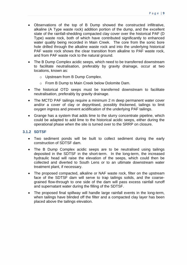
P a g e | 9
Observations of the top of B Dump showed the constructed infiltrative, alkaline (A Type waste rock) addition portion of the dump, and the excellent state of the rainfall-shedding compacted clay cover over the historical PAF (D Type) waste rock, both of which have contributed significantly to enhanced water quality being recorded in Main Creek. The core from the sonic bore hole drilled through the alkaline waste rock and into the underlying historical PAF waste rock shows the clear transition from alkaline to PAF waste rock, and from PAF waste rock to the natural ground.
The B Dump Complex acidic seeps, which need to be transferred downstream to facilitate neutralisation, preferably by gravity drainage, occur at two locations, known as:
o Upstream from B Dump Complex.
o From B Dump to Main Creek below Dolomite Dam.
The historical OTD seeps must be transferred downstream to facilitate neutralisation, preferably by gravity drainage.
The MCTD PAF tailings require a minimum 2 m deep permanent water cover and/or a cover of clay or depyritised, possibly thickened, tailings to limit oxygen ingress and prevent acidification of the underlying PAF tailings.
Grange has a system that adds lime to the slurry concentrate pipeline, which could be adapted to add lime to the historical acidic seeps, either during the operational phase when the site is turned over to the SRRP on closure.
3.1.2 SDTSF
Two sediment ponds will be built to collect sediment during the early construction of SDTSF dam.
The B Dump Complex acidic seeps are to be neutralised using tailings deposited in the SDTSF in the short-term. In the long-term, the increased hydraulic head will raise the elevation of the seeps, which could then be collected and diverted to South Lens or to an ultimate downstream water treatment plant, if necessary.
The proposed compacted, alkaline or NAF waste rock, filter on the upstream face of the SDTSF dam will serve to trap tailings solids, and the coarse-grained flow-through to one side of the dam will pass excess rainfall runoff and supernatant water during the filling of the SDTSF.
The proposed final spillway will handle large rainfall events in the long-term, when tailings have blinded off the filter and a compacted clay layer has been placed above the tailings elevation.

P a g e | 10
3.2 Site Visit
The Peer Review Panel visited Savage River Mine on Monday 17 December 2012, accompanied by Bruce Hutchison of Grange and Stephen Kent.
3.2.1 North Pit
Views of the current North Pit are shown in Figures 1 and 2, which highlight the constraints imposed on mining by pit wall instability that is continuously monitored by radar.
Figure 1 Instability on East face of North Pit
(a) (b)
Figure 2 North Pit: (a) mining, and (b) radar monitoring
The pit is currently 180 m deep. Following previous failures of the west face and its cut-back to 35o, and more recent east face failures, mining is currently restricted to the upper northern bench and the northern lower bench (outside the east face failure zones). The east face failure is along geological structure at 55o, compared with the original 61o cut, and will necessitate a cut-back (from top) to 55o to enable remining.
Radar measures displacements (in line with the beam, not parallel to it) to an accuracy of 0.1 mm. A 1.5 mm/hour face movement raises the Geotechnical Alarm, requiring geotechnical stability assessment. A 2 mm/hour face movement signals the evacuation of personnel and equipment, typically providing 36 to 48 hours warning of failure.

P a g e | 11
3.2.2 Broderick Creek Flow-Through
Views of the current Broderick Creek flow-through are shown in Figure 3.
(a) (b)
Figure 3 Broderick Creek flow-through: (a) looking downstream, and (b) looking upstream over end-dumped crest
Broderick Creek flow-through is currently at its planned maximum length of 3.7 km, and measures an average 50 m wide by 20 m deep (this compares with the proposed 20 m wide full-height SDTSF dam flow-through). The flow ranges from about 0.5 to 2 m3/s.
In addition to the current base flow-through, middle and upper flow-through drains are being planned, separated by compacted clay layers, to provide capacity in the event of base flow-through blocking at some time in future.
Directing flow-through to North Pit on closure has been considered, to capture alkalinity and flood the North Pit PAF walls.
3.2.3 South Deposit Pit
Views of the flooded South Deposit Pit and the current stripping of clay for the extension are shown in Figures 4 and 5, respectively.
Figure 4 Flooded South Deposit Pit

P a g e | 12
(a) (b)
Figure 5 South Deposit Pit: (a) stripping clay, and (b) forming track to base of SDTSF
South Deposit Pit took 6 years to flood. The pit water is at a pH of about 8, and overflows to Savage River at RL 260 m. The pit will be extended mainly to the south-east towards Main Creek, with a connecting cut at about RL 240 m, about 20 m below the overflow to Savage River (allowing eventual overflow to Main Creek). Clay and gravels down to rock are currently being excavated. It is proposed that PAF waste rock, which is expected to comprise only about 5% (based on the latest acid base accounting assessment of the waste rock, completed on 13 January 2013) of all waste excavated from the extended pit, will be isolated in a dedicated cell within the Downstream Waste Rock Dump beyond the SDTSF dam.
3.2.4 SDTSF
The proposed SDTSF is to be located in Main Creek, downstream of MCTD and adjacent to South Deposit extension, as shown in Figures 6 and 7. The dam crest is proposed to rise to RL 300 m, c.f. about RL 380 m at the top of B Dump (the original surface was at about RL 360 m, with historical waste rock end-dumped over the Main Creek valley wall), and the current RL 333 m MCTD wall crest.
Figure 6 Looking towards location of proposed SDTSF dam

P a g e | 13
(a) (b)
Figure 7 Base of proposed SDTSF dam in Main Creek: (a) looking upstream, and (b) looking downstream
It is proposed to construct the SDTSF dam by selectively using waste rock from the South Deposit Pit extension, involving the following stages:
Grub the south abutment (to achieve a seal), and remove trees from the north abutment (adjacent to the flow-through).
Face the upstream face of the dam with a compacted filter comprising South Deposit extension alkaline and NAF waste rock.
Selectively end-dump coarse-grained alkaline waste rock to form a flow-through on north abutment.
The initial end-dumped tip-head height will be 30 to 40 m.
Construction will continue as a sequence of lifts.
The permeability of the filter and hence of the flow-through will be tested as the dam is constructed by monitoring weekly the upstream water level, the cross-section and the downstream flow and level:
o If the flow and/or sediment load are too high, the upstream face could be faced with clay.
o If the flow is too low, the level of compaction of the filter may be reduced.
The particle size distribution of the filter material will be monitored to ensure that filter criteria are met to prevent the transport of the adjacent tailings.
On closure, sealing of the filter by settled tailings and a compacted clay layer placed down to the elevation of the tailings will minimise flow-through, and a spillway constructed to maintain a water cover over the PAF tailings and pass high rainfall events.
A submission for the SDTSF was made by Grange to the Government Dam Assessors (ACDC) in late May 2012, GHD completed the SDTSF design in November 2012, and the Peer Review (by Professor David Williams) is due for completion by mid-January 2013. Approval of the SDTSF design is hoped to be granted by October 2013, to enable the timely start of dam construction. Any delay will force the storage of South Deposit Pit extension waste rock elsewhere, and the

P a g e | 14
sourcing of alternative suitable waste rock and clay from elsewhere on the site, more distant from the SDTSF dam. Dam construction is expected to take about 18 months. No tailings will be deposited in the SDTSF until 12 months after the commencement of dam construction, requiring adequate MCTD capacity and hence timely completion of the SDTSF dam. SDTSF will provide tailings storage capacity until 2030, with Centre Pit South accommodating tailings from Long Plains, if it proceeds after 2030.
3.2.5 B Dump
Figure 8 shows a surface drain on the infiltrative, alkaline portion of B Dump, while Figure 9 shows the degraded, 3-year old, sonic core through B Dump waste rock. Figure 10 shows the impressive natural revegetation of the compacted clay, rainfall-shedding cover over the historical PAF waste rock in B Dump.
Figure 8 Surface drain on infiltrative, alkaline portion of B Dump
Figure 9 Degraded, 3-year old, sonic core through B Dump waste rock
Surface
Transition from alkaline to historical
PAF waste rock
Original ground

P a g e | 15
Figure 10 Natural revegetation of compacted clay, rainfall-shedding, cover over historical PAF waste rock in B Dump
3.2.6 MCTD
A view of the MCTD wall and tailings storage from B Dump is shown in Figure 11.
Figure 11 View of MCTD wall and tailings storage from B Dump
The MCTD wall is currently at RL 333 m (which will provide capacity for at least 8 months tailings production), with approval to be sought to go to a maximum of RL 338 m (to provide capacity to the end of 2017; although RL 336 m may be the final height), requiring a downstream buttress at road level, possibly comprising waste rock mined from a re-opened Centre Pit.
The tailings remain alkaline for at least 2 years, before the available alkalinity is exhausted and acidity rises.
Two cover trials are being constructed on the MCTD coarse-grained tailings beach, comprising:
1. 1 m of clay.
2. 0.5 m of clay, overlain by 0.5 m of waste rock.
The cover materials are delivered by an articulated, all-wheel drive truck and spread using a D7-equivalent dozer, as shown in Figure 12. Placing the clay in a single 1 m lift causes relatively little “bow-waving” of the tailings beyond the toe of the fill, while placing just 0.5 m height of clay leads to considerable bow-waving due to the weight and vibration of the dozer, as shown in Figure 13. Monitoring of the trials is limited to a number of piezometers, with no vane shear strength testing, which would be useful in assessing strength gain on dissipation of excess pore water pressures generated by the placed fill.

P a g e | 16
Figure 12 Placing trial cover on MCTD tailings, incorporating 0.5 m of alkaline waste rock over 0.5 m of clay: (a) dumping clay, and (b) dozing clay
(a) (b)
Figure 13 Trial cover on MCTD tailings, incorporating 0.5 m of alkaline waste rock over 0.5 m of clay: (a) side of trial cover, and (b) detail of bow waving of tailings due
to weight of placed clay and dozer used to place it
3.2.7 Acidic Seeps rom B Dump Complex Below MCTD
The historical upstream acidic seep from B Dump Complex to Main Creek, and the acidic seep from B Dump to Main Creek below Dolomite Dam, are shown in Figures 14 and 15, respectively. The acidic seeps from B Dump Complex have a pH of about 3.5.
These seeps are expected to rise with the hydraulic head provided on tailings deposition in the SDTSF, and an eventual 1 m deep pond is proposed to contain the seeps, bunded off from the tailings located at an elevation 1 m higher and permanently covered by a 2 m depth of water, from where the acidic seeps can be drained by gravity pipeline to an ultimate downstream water treatment plant post-closure (a strategy approved by the SRRP).

P a g e | 17
(a) (b)
Figure 14 Upstream acidic seep from B Dump Complex to Main Creek: (a) looking upstream, and (b) looking downstream
(a) (b)
Figure 15 Acidic seep from B Dump to Main Creek below Dolomite Dam: (a) B Dump angle of repose slope, and (b) V-notch weir recording flow rate
3.2.8 OTD Seeps
The historical OTD acidic seeps, shown in Figure 16, which rise to the surface of the tailings in the MCTD, are being retained against the OTD wall, and are rapidly neutralised by the MCTD tailings.
Ultimately, it is proposed to create a 1 m deep pond to contain the OTD seeps, bunded off from the tailings located at an elevation 1 m higher and permanently covered by a 2 m depth of water, from where the acidic seeps can be drained by gravity pipeline to an ultimate downstream water treatment plant post-closure (a strategy approved by the SRRP).
The adoption of this strategy requires a prior decision by the SRRP regarding the elevation to which the MCTD wall and tailings will reach. If the MCTD wall is taken to RL 338 m, the pipeline will need to be laid and cut through along the western bank of the MCTD in advance, with a clay cover over a 200 m length of the coarse-grained beach, and a minimum 2 m deep permanent water cover over the remainder of the beach.

P a g e | 18
If the MCTD wall is constructed to RL 336 m and tailings raided to RL 338 m at the northern end of the storage, a pipeline can be placed later. However, this will lead to a less desirable 2 m deep pond towards the MCTD wall and a 200 m wide clay cover towards the OTD.
(a) (b)
Figure 16 OTD seeps to surface of MCTD tailings: (a) acidic water at source of OTD seeps, and (a) rapid neutralisation of OTD seeps by MCTD tailings
3.3 Meetings with Consultants
The meetings with Grange and their Consultants GHD and Lois Koehnken took place on Tuesday 18 December 2012 in GHD’s Hobart Office. Notes from these meetings, including points made by the Peer Review Panel, are contained in the following sections.
3.3.1 SDTSF Design and Construction
The key points of the proposed design and construction of the SDTSF dam are summarised in the following:
The cut-through from South Deposit Pit will be at RL 220 m, to the top of first lift of the SDTSF dam in Main Creek at RL 194 m.
South Deposit Pit extension is still to be optimised, including optimisation of the PAF Dump (to avoid a need to move it).
The Dam Consolidation Section (DCS) is to be constructed in 2 m thick, paddock-dumped layers of alkaline and NAF waste rock, dozed and pushed out to limit settlement, to form 10 m high lifts that support the 20 m thick base and abutment alkaline flow-through drains, and support the subsequently-placed and compacted 30 m thick alkaline and NAF filter zone (placed in 2 m thick layers).
The downstream shell will provide stability to the SDTSF dam, and is proposed to comprise largely alkaline and NAF waste rock, dumped in 10 to 20 m high lifts.
The permeability of the filter and hence of the flow-through will be tested as the dam is constructed by monitoring weekly the upstream water level, the cross-section and the downstream flow and level, and making adjustments to the placement methodology to achieve the desired flow-through.

P a g e | 19
The assumed permeability of the compacted filter is in the range from 10-4 to 10-6 m/s (4.3 x 10⁻⁵ to 1.2 x 10⁻⁴ m/s was back-calculated from the results of a trial of a compacted filter conducted on site, impounding water and tailings. In the trial, no seepage or tailings emerged downstream; the pores merely wet-up with no more than about 15 mm penetration of tailings solids, and the pore water was relatively clean).
The assumed permeability of the tailings slimes is 10-7 (perhaps horizontally) to 10-8 m/s (perhaps vertically); noting that segregation and consolidation may be minimal as deposition will always be into a pond.
Filter criteria will be applied between the tailings slimes and the filter, and between the filter and the alkaline flow-through, to ensure that piping of fines will not occur.
The lowest level of the SDTSF dam will be placed into water (in the Main Creek channel), making it difficult to compact filter, and possibly requiring a clay cover.
The alkaline flow-through will be constructed by pushing alkaline waste rock over a series of tip-heads as the dam elevation rises, relying on segregation on ravelling over the angle of repose face to create a coarse-grained flow-through.
A Closure Section is proposed above the DCS, including a compacted clay layer on the upstream face above the elevation of the tailings to limit seepage post-closure.
A Downstream Buttress, if constructed (using surplus waste rock from South Deposit Pit extension), will have an alkaline flow-through drain below it.
The Peer Review Panel made the following recommendations and suggestions to GHD in relation to the design, construction and operation of the SDTSF:
The ideal is to design and construct the SDTSF filter to allow just enough flow-through to maintain the tailings saturated during deposition (and, as a bonus, adding alkalinity to Main Creek), and to reduce flow-through on closure:
o Optimal flow-through during tailings deposition is dependent on the filter.
o Reduced flow-through on closure will rely on the sealing effect of the tailings (a contingency would be grouting) and clay placed and compacted above the bench provided on the upstream face of the dam down to the tailings elevation, with a filter behind to protect against possible piping of clay, and ensure adequate drainage of the dam to maintain geotechnical stability.
Construction observation and monitoring, of the performance of the filter in particular, is critical to confirming, and modifying if required, the design and construction of the SDTSF dam.
Construction of the entire SDTSF dam should be recorded by at least weekly photographs and appropriate QA/QC testing of the different zones.

P a g e | 20
Periodic reviews of and adjustments to the operation and closure of SDTSF are recommended.
The water level in the SDTSF storage will rise quite quickly in the 6 months before any tailings are deposited, backing-up to the downstream acidic seep from B Dump to Main Creek below Dolomite Dam. Within the next year of tailings deposition, the pond level will rise to the upstream B Dump Complex acidic seep and stay there for several years due to the sharp rise in elevation above that point. Hence, the majority of the deposited tailings will remain underwater.
The tailings rate of rise in the SDTSF will be very high initially, reducing towards 2 m/year towards the end of deposition.
The SDTSF will be about 2 km long, implying up to a 20 m change in elevation of tailings surface if discharge is from the upstream end only, and requiring that the tailings discharge may need to be controlled to maintain the pond and saturation of the tailings (ensuring no exposure within 2 years), and to facilitate an ultimate water cover. However, this is mitigated by the rapid development of a large pond.
The tailings are proposed in the design of the SDTSF to be discharged from the dam towards closure to limit the depth of water at the dam on closure (pushing the greatest water depth away from the dam), but this would result in an elevated beach comprising more permeable and more pyrite-rich coarse-grained tailings against the filter, with consequent higher flow-through rates, and dewatering and oxidation of the tailings. Care must be exercised to avoid depositing coarse-grained tailings against the SDTSF dam. Where this is unavoidable for short periods, compacted clay should be placed against the filter in advance.
Premature closure may lead to exposure of the upper tailings beach; hence the need to control the tailings discharge (including the possibility of tailings discharge from down the valley), to minimise the area requiring a clay cover.
World precedents for the SDTSF concept identified by the Peer Review Panel are:
Broderick Creek alkaline flow-through, which has only been dry upstream about twice in 14 years, and has no filter.
Antamina TSF, Peru, involved a waste rock dam with a concrete face (as is South American practice) to form a seal, and an underlying engineered filter to capture fines and drain any leakage. This design later required a geomembrane to limit leakage, since the tailings were beached away from the dam and were more permeable than expected.
Porgera TSF, PNG, wanted a leaky dam, and achieved it in a similar way to what is proposed for the SDTSF dam, with an upstream filter (not relying on the tailings being of low permeability).
Paracatu TSF, Brazil, which was constructed by the centreline method using residual saprolites, since a water-retaining dam was required.
Gosowong WRD flow-through, Indonesia.

P a g e | 21
Coarse reject flow-through dams for tailings storage in the NSW and Queensland coalfields, without a filter (tailings blind and seal the upstream face).
The Peer Review Panel made the following comments on issues related to the SDTSF:
The OTD and B Dump Complex acidic seeps (carrying up to 0.7 tpd of acidity, and flowing at up to 50 l/s) will eventually be covered by ameliorating alkaline tailings.
The gravity pipeline proposed to carry the OTD acidic seeps (up to 2.3 tpd, and up to 10 l/s) past MCTD (agreed by and paid for by SRRP) must be accommodated within the SDTSF (logically at the B Dump Complex acidic seeps). Precipitates (ferric and aluminium hydroxides) will aid flocculation.
The expected final tailings pond level in the SDTSF (at RL 297 m) could drop an estimated maximum of 1 m with 90 days of no rainfall (based on 8 to 10 l/s seepage through the dam; although at the Savage River Mine the only month with a net rainfall deficit is January).
The MCTD maintains a pond, as does the OTD, despite leaky walls; and the OTD pond has reasonable water quality (total dissolved solids [TDS] of about 265 ppm, pH of about 3.5, SO4 concentration of about 225 ppm, and Cu concentration of about 0.15 ppm).
There will be 60 times (about 600 l/s) as much flow in Main Creek as the predicted seepage through the SDTSF dam of about 10 l/s (about 1 to 2 t CO3/day; leading to very minor long-term settlement), so the dam will mostly spill and the pond will be maintained.
The SDTSF dam filter should also remain essentially saturated, limiting oxygen penetration of the adjacent tailings, as seen for the tailings beach adjacent to the leaky MCTD wall. A contingency could be the construction of a pond at the toe of the dam to seal off the flow-through from oxygen ingress.
There is more than enough alkalinity within proposed SDTSF dam flow-through to last over 1,000 years.
Assuming a 35 Mt SDTSF dam mass, losing 700 tpa due to neutralisation, or 0.002%/year, 0.02%/10 years, 0.2%/100 years, 2%/1,000 years, or 400 mm settlement of the proposed 20 m high flow-through, or perhaps 40 mm actual settlement, since the flow-through will not flow full.
3.3.2 Geochemical Assessment of Tailings
This assessment by the Peer Review Panel was based on reports of Clayton Rumble and Danny Ray:
In 1999, the Main Creek valley contributed approximately 40% of the Cu and 35% of the Al entering the environment from the Savage River mining leases.
Water quality data from 2010-2011 suggest that overall fluxes from the site have decreased compared with 1999, but Main Creek continues to contribute about 35% of the total Cu and 25% of the Al entering the environment from the site.

P a g e | 22
The PAF tailings have well-distributed (being fine-grained), and inherent alkalinity (calcite and dolomite-derived).
SO4 release and CO3 consumption in exposed PAF tailings are relatively slow (and balanced), implying relatively long lag periods (at least 2 years, if unsaturated).
Hence, tailings neutralisation of acidic seeps is feasible during operations (but not post-closure, when the acidic seeps would over time require some other form of treatment).
The acidity load from the OTD seeps is about 730 tpa.
Cu is only metal of note.
3.3.3 Environmental Benefits of SDTSF
The environmental benefits of the SDTSF identified by the Peer Review Panel are:
The addition of alkalinity to Main Creek via the SDTSF dam alkaline flow-through.
The interception and neutralisation by tailings during deposition of the B Dump Complex seeps.
The potential transfer of the OTD acidic seeps and collection of B Dump Complex acidic seeps, facilitating their ultimate treatment, if supported by the SRRP.
Alternatively, any residual acidic seeps could ultimately be drained to South Deposit Pit.
3.3.4 Broderick Creek Flow-Through
The performance of the Broderick Creek alkaline flow-through offers support for the success of the proposed SDTSF dam alkaline flow-through:
Alkalinity generated by the Broderick Creek alkaline flow-through has risen over time and with its increasing length to almost 3.4 mg/l, with lower flows producing higher alkalinity.
The outflow from the Broderick Creek alkaline flow-through cycles between a dry season (summer) low of 0.1 to 0.35 (increasing with flow-through length and/or varying with climatic conditions) to a wet season (winter) high of about 1.85 m3/s.
The lowest water level at the upstream end of the Broderick Creek alkaline flow-through has been about RL 152 m and highest about RL 186.2 m (a 34 m range).
The water level at the downstream end of the Broderick Creek alkaline flow-through has ranged from RL 148 m to RL 101 m, as the flow-through has been extended downstream.

P a g e | 23
3.3.5 Pipeline to Gravity Drain OTD Acidic Seeps
The proposed pipeline to gravity drain the OTD acidic seeps would run along the final western perimeter of the MCTD, cut through the lower level ETD to the base of the MCTD wall, then join the two B Dump Complex acidic seeps as they rise along the final perimeter of the SDTSF, with a U-bend towards the downstream end to prevent oxygen entering the pipeline and causing iron scaling. The pipeline gradient would be 0.5% around the MCTD, and 1% below the MCTD wall.
3.3.6 Regulatory Structure
The Regulatory structure under which the Savage River Mine operates and, in particular, under which the SDTSF will be assessed, is summarised in Figure 17.
Figure 17 Regulatory structure governing Savage River Mine
3.3.7 Site Acidity
This assessment was based on reports prepared and presented by Lois Koehnken:
In Savage River, alkalinity has increased about 3-fold, acidity has dropped, metals have dropped about 3-fold, and SO4 has halved.
Old dumps are acidic, and Cu and SO4-rich.
New dumps are alkaline and Cu-deficient, with minor Fe, Mn and Zn.
Toxicity (concentrations), having been well above fish targets, are now approaching fish targets, particularly for medium (0.5 to 1 m3/s) and high flows (> 1 m3/s).
No Grange PAF Dumps have shown seepage, presumably due to encapsulation, and hence do not appear to be adding any acidity to the site.
Grange alkaline flow-through dumps and encapsulations are adding alkalinity to the site.
EPA Board
Assessment Group Malcolm Budd
David Oldmeadow
SRRP Alison Hughes
Assessment Committee for Dam Construction
Sam Dichfield
Regulators John Langenberg
Director Alex Schapp

P a g e | 24
4. PEER REVIEW PANEL PRESENTATION AND QUESTIONS
Professors David J Williams and G Ward Wilson, and Dr Jeff Taylor made a presentation to the EPA in Hobart on 19 December 2012, which is given in the following sections.
4.1 Review of Geochemistry
4.1.1 Methodology
Assessment of tailings:
o Tailings are PAF, with alkalinity.
o Lag period >> 2 years, as incorporated into successful adaptive management of MCTD.
Design to control oxidation in short and long-terms.
Minimising impacts of historical ARD on operations and closure:
o Optimising use of available alkalinity to neutralise historical acidic seeps (SRRP and Grange).
o Plan post-closure logistics of ARD management/ treatment (SRRP).
4.1.2 Short and Long-Term Risks and Uncertainty
Desaturation of tailings leading to consumption of available alkalinity and acidification – avoided by limiting exposure and a final water cover.
Tailings oxidation via air-entry up flow-through, leading to acid generation – unlikely due to expected near saturation of filter.
Post-closure impacts associated with historical ARD sources:
o Oxidation of tailings (Fe3+).
o Consumption of available alkalinity.
o Acidity and metals in Main Creek and Savage River.
4.1.3 Contingencies
Maintain SD tailings saturated during operation of TSF and post-closure by:
o Depositing tailings fines against the dam filter.
o Controlling tailings deposition to minimise exposure.
o Permanent water cover post-closure.
Maintain filter saturated below tailings during operation of TSF and post-closure, to control air-entry to tailings via flow-through.
Continuous slow discharge into flow-through.
Alkalinity addition downstream via flow-through.

P a g e | 25
Plans for control of historical ARD during SDTSF operation and post-closure:
o Gravity pipeline taking OTD and B Dump Complex acidic seeps to ultimate downstream water treatment plant (strategy already approved by SRRP).
4.2 Review of SDTSF Dam Design and Construction Implications
4.2.1 World Leading Practice Design Methodology
Construction entirely using NAF or Alkaline materials.
Allowing adequate flow-through to maintain tailings saturated during deposition, and to increase alkalinity to Main Creek, addressed by:
o Observation and monitoring of flow rates during and post-construction.
o As demonstrated by successful adaptive management of MCTD.
Followed by reduced flow-through on closure.
Ensuring long-term tailings saturation via a permanent water cover post-closure.
4.2.2 Design Elements
Upstream compacted filter zone, designed according to well-established filter criteria (tailings fines interfacing with filter and filter interfacing with flow-through).
20 m wide upstream, base and abutment rock fill flow-through.
Compacted rockfill zone constructed in 2 m layers and 10 m lifts to support flow-through and compacted filter, and closure zone above.
Downstream rockfill buttress.
On closure, seal on upstream face, comprising tailings fines and compacted clay.
4.2.3 SDTSF Dam Zones and Design Functions
The zones of the proposed SDTSF dam are shown in Figure 18, with a description of the design functions of each zone given in Table 1.
Figure 18 Zones of proposed SDTSF dam

P a g e | 26
Table 1 Design functions of SDTSF dam zones
ZONE DESIGN FUNCTION
Foundation Provide a sound foundation for SDTSF dam, involving grubbing south abutment (to achieve a seal), and removing trees from north abutment (adjacent to flow-through)
Flow-through Ready drainage of water entering filter zone
Compacted Zone Stable dam to support sloping flow-through and filter zone, and ultimate closure zone
Filter Zone
Allow just enough flow-through to maintain the tailings saturated during deposition (and, as a bonus, adding alkalinity to Main Creek), and to reduce flow-through on closure
Downstream Buttress
Add further geotechnical stability to dam
Extended flow-through
Provide outlet for flow-through beneath downstream dump
Downstream dumpAccommodate remaining waste rock from South Deposit Pit extension, including all PAF waste rock, to be placed in an isolated cell
Closure zone
Allow upper filter zone not covered by tailings to be sealed with compacted clay to limit ongoing seepage through SDTSF dam, while maintaining geotechnical stability, post-closure
4.2.4 Construction Technique
Flow-through demonstrated at Savage River by successful implementation at Broderick Creek.
Worldwide precedents include:
o Flow-through dams of coarse reject to store tailings at coal mines in NSW and Queensland.
o Antamina TSF, Peru, involving a rockfill dam with a filter and tailings.
o Porgera TSF, PNG, involving a rockfill dam with a filter and tailings.
o Gosowong, Indonesia, rockfill flow-through.
4.2.5 Construction Practice
World leading practice adaptive management to ensure design criteria are met.
Drawing upon mine personnel, consultants and contractors with appropriate site experience.
Rigorous and continuous materials selection, characterisation, scheduling, and QA/QC.
Continuous observation and monitoring of flow rates during and post-construction to ensure compliance with design flow-through.
Refinement of construction methodologies.

P a g e | 27
4.2.6 Geotechnical Calculations.
Consistent with leading practice
Potential materials variability:
o Materials have been appropriately characterised for design.
o Materials variability will be managed by construction QA/QC.
Quality assurance and control (QA/QC) programs:
o Well-developed through site personnel, consultants and contractors.
4.2.7 Physical Functioning and Materials Interactions
Adequately planned for, and appropriate for site environment.
4.2.8 Risks and Contingencies
Loss of involvement of competent and experienced staff to ensure built-to-design – Team approach.
Premature mine closure – Planned for.
Delayed construction – Losing source of materials and limiting scale of dam.
4.2.9 Potential for Tailings Release and/or Oxidation
Low risk, given conservative design and demonstrated site performance.
4.2.10 Long-Term Extreme Weather Effects
Extreme events have been used for design.
4.3 Review of SRRP
4.3.1 Meeting Stated Objectives of 2012 SRRP Strategic Plan
SDTSF will lead to best opportunity to promote a modified but healthy eco-system in Savage River.
Provides 20 years of water treatment without additional CapEx or OpEx (reagent and maintenance costs).
4.3.2 Integration of SDTSF into Remediation of Historical ARD
Capture & treat OTD and B Dump Complex acidic seeps during mine life.
Will immediately improve water quality in Main Creek and Savage River.
OTD diversion protects integrity of MCTD.
Passively adds alkalinity to Main Creek.
4.4 EPA Questions and Peer Review Panel Responses
Following the presentation, the EPA asked a number of questions, which are repeated and answered in the following sections.

P a g e | 28
4.4.1 General Questions and Comments
The Peer Review Panel offer the following general comments in answer to general questions raised by the EPA:
The design of the SDTSF provides an integrated interface between the geochemistry of and geotechnology applied to the tailings.
There is a greater than 2-year lag in the generation of acidity from the tailings on exposure to oxygen, and the operators and their Geotechnical Engineer must avoid excessive exposure of tailings during deposition (always less than 2 years) and post-closure (by flooding).
Main Creek experiences large inflows that are of the order of 60 times the expected flow-through the SDTSF dam; hence, saturation of the tailings can be maintained during tailings deposition, and a minimum 2 m deep permanent water cover maintained post-closure.
A gravity pipeline can transfer OTD and B Dump Complex acidic seeps to an ultimate water treatment plant downstream of the SDTSF.
There is a clear independence between Grange and the Peer Review Panel:
o The role of the Peer Review Panel is to examine the SDTSF design and supporting documents for fatal flaws and high risks.
o The Peer Review Panel Report will become an Appendix to the Grange DPEMP.
On the question of the longevity of worldwide precedents:
o Flow-through dams of coarse reject to store tailings at coal mines in NSW and Queensland have been in use for several decades, starting in NSW and currently in Queensland (e.g. Oaky Creek).
o Antamina TSF, involving a rockfill dam with a filter and tailings, has been in operation for more than 10 years, and is currently over 200 m high.
o Porgera TSF, involving a rockfill dam with a filter and tailings, has been developed in a series of expansions over the last 5 years.
On the question of mistakes, construction, operation and closure are all important, and the experience and continuity of the operators and their consultants are key to managing any risks.
The causes of failures of TSF dams include piping failures, including around pipes through dams, which was an issue in the early stages of the MCTD. Particular attention should be paid to maintaining filter criteria (to entrap fines), and pipes should be avoided.
In the long-term, a diversion to pass OTD and B Dump Complex acidic seeps to an ultimate water treatment plant downstream of the SDTSF or to the mined out South Deposit Pit is essential, funded by the SRRP and facilitated by Grange.

P a g e | 29
4.4.2 Specific Questions on Geochemistry
EPA Question – What is Grange/Panel’s understanding of the geochemistry of the tailings, with particular reference to the two papers on assessment of ARD neutralisation using tailings from the mine site (Aquatic Science & GEM, 2009 and GEM 2010)?
EPA Note – Aquatic Science & GEM, 2009 – page 19, changes in sludge densities and volumes with addition of OTD/B Dump Complex seeps and GEM, 2010 – what is driving changes in decant water and leachate chemistry, what is controlling the lag time to acid onset, and why does the addition of OTD/B Dump Complex seeps increase the lag time to acid onset?
Panel Response – Pyrite within the tailings is the key acid generating constituent. The pyrite begins to oxidise immediately on exposure to oxygen, generating acidity. The acidity is initially neutralised by the available Acid Neutralising Capacity (ANC), but the acid generating capacity of the tailings exceeds the ANC. The ANC is mainly carbonate, which releases rapidly, is about 30% available, and has much greater than 2 years neutralising capacity; and even more if the tailings are moist, since this limits oxidation and catalyses alkalinity generation. Adding acidic seeps to the tailings leads to a rise in the pH of the seepage water, and in turn reduced solubility of metals, and/or precipitation of dissolved metals; and results in reduced Cu due to the secondary oxidation of Fe2+ to Fe3+.
EPA Question – What is the effective capacity of tailings to neutralise the historical seeps (OTD, B Dump Complex, and MCTD wall seeps)? In particular, what level of confidence is there in scaling up the laboratory test results presented in the above two papers to that of the proposed project?
EPA Note – That is, how well do the studies mimic what is actually proposed?
Panel Response – Scaling-up to field scale will work better than the results from wetting and drying cycles applied to tailings in columns at laboratory scale, due to the moist to saturated conditions prevailing in the MCTD and the proposed SDTSF; that is, the laboratory testing represents a worst case due to full drying.
EPA Question – Describe how the OTD seeps will be captured and how they will be mixed with tailings to maximise neutralisation? Describe how the B Dump Complex seeps will be captured and mixed with tailings to maximise neutralisation?
EPA Note – If the B Dump Complex seeps are not mixed with tailings, but left to seep “naturally” into the SDTDF and onto tailings not covered by water, is there an increased risk of acid generation before adequate cover by other tailings or water? That is, will it decrease the 2-year lag time to acidification?
Panel Response – The B Dump Complex seeps will be forced up with the tailings deposited in SDTSF, taking the path of least hydraulic gradient. Provided that the SDTSF tailings beach is locally maintained higher than the points of egress of the seeps, and the tailings are maintained mainly saturated, they will neutralise the seeps. The flow rate of the seeps is insignificant compared with the rate of deposition of the tailings, and so will have a negligible impact on the neutralisation capacity of the tailings during their deposition.

P a g e | 30
EPA Comment – Providing infrastructure to collect seeps is critical for the operation and closure of SDTSF; Koehnken, 2012).
Panel Response – Funding for this infrastructure is the responsibility of the SRRP, but can be facilitated by Grange activities.
EPA Question – What is the level of risk to the SDTSF associated with uncertainties in seepage mass loads, including the possibility of in complete capture of B Dump Complex, Main Creek Tailings Dam wall and Emergency Tailings Dam wall seeps?
EPA Note – During high flows, the B Dump Complex seeps may be entering Main Creek downstream of MCTD. Seeps along original creek topography may be possible. Poor mass balances were obtained during high flows, which could be attributed to extra seeps, the storage of sediments and metal hydroxides in the river, and altered flow conditions (Koehnken, 2012). Will further work be undertaken to identify/quantify the acidic seeps as access to the area is improved?
Panel Response – The increase in tailings volume due to gypsum formation on adding the relatively small volume of acidic seeps (of the order of 3 to 5 tpd, compared with the much larger volume of tailings deposited in the SDTSF of about 8,000 tpd) is estimated to be << 1%.
EPA Question – What is the risk of incomplete capture of the OTD seeps, with particular reference to the long-term geochemical stability of the MCTD and downstream environment, inclusive of the SDTSF?
EPA Note – This leads to the question of why the MCTD will acidify if OTD seeps are not removed; what is driving this? Note, seeps enter the MCTD via groundwater movement. Groundwater movement is poorly understood. The risk could be assessed and possibly managed through a MCTD monitoring program on closure (Koehnken, 2012).
Panel Response – The OTD seeps have been observed to follow the rising surface of the MCTD tailings, and will be captured in the “sink” proposed by surrounding them with a bund to maintain the seeps about 1 m lower than the deposited tailings on the downstream side of the bund. From this sink, it is proposed to gravity feed the acidic seepage, via the SDTSF to an ultimate downstream water treatment plant post-closure, preserving the geochemical stability of the MCTD, SDTSF and the downstream environment. The gravity pipeline will incorporate a U-bend towards its downstream end to stop oxygen ingress and prevent scaling of the pipe.
EPA Question – How will variations in the ANC/PAF potential of the tailings be managed to ensure neutralisation of the acidic seeps, including flooding of the tailings before the onset of net acidity?
EPA Note – What monitoring programs are in place for acidic seepage collection and mixing. During the life of the project, ore bodies with differing geochemistry may be accessed, e.g. that from South Central Pit. Will the neutralising capacity and time to acidification alter from 2 years?
Panel Response – Based on worst case laboratory testing, the lag period for the tailings to go acid is >> 2 years, providing a more than adequate factor of safety to allow for possible variations in the ANC/PAF potential of future tailings.

P a g e | 31
EPA Question – What contingencies are in place for unforseen fluctuations in the resource, and hence tailings availability (for neutralisation)?
Panel Response – Grange is continually evaluating alternative sources of ore to cover the possibility of pit instability or exhaustion halting ore supply, including the proposed extension of South deposit Pit, and the possible future re-mining of other pits.
EPA Question – What is the risk to the SDTSF from fluctuations in water level during operation?
EPA Note – This question is in reference to potential acid pulses from the flooding of the B Dump Complex, with subsequent water level drops and associated discharge from the dump.
Panel Response – During the construction of the SDTSF dam, monitoring of the performance of the flow-through (based on upstream water levels, the cross-section and the flow-through rate), will be used as a basis for refining the filter, if required, to achieve the design flow-through rate, and maintain saturation and geochemical stability. If the flow-through rate and/or sediment load are found to be too high, the upstream face could be faced with clay. If the flow-through rate is found to be too low, the level of compaction of the filter may be reduced.
EPA Question – Where will the B Dump Complex acidic seeps be directed? What contingencies will be in place to manage and control any acidic seeps?
Panel Response – It is proposed to drain the B Dump Complex acidic seeps via a gravity pipeline to an ultimate downstream water treatment plant in Main Creek post-closure (a strategy approved by SRRP, which has responsibility for funding this). A possible contingency would be to gravity drain or pump the B Dump Complex acidic seeps to South Lens Pit for neutralisation.
4.4.3 Specific Questions on Dam Design and Construction
EPA Question – The permeability of filter is critical to the functioning of the SDTSF. How will this permeability be monitored during construction? What measures will be in place to achieve the design permeability? What contingencies will be in place if the design permeability cannot be achieved?
Panel Response – During the construction of the SDTSF dam, monitoring of the performance of the flow-through (based on upstream water levels, the cross-section and the flow-through rate), will be used as a basis for refining the filter, if required, to achieve the design flow-through rate, and maintain saturation and geochemical stability. If the flow-through rate and/or sediment load are found to be too high, the upstream face could be faced with clay. If the flow-through rate is found to be too low, the level of compaction of the filter may be reduced.

P a g e | 32
EPA Question – How will the tailings alter the permeability of the filter? How will the release of tailings in the upper Main Creek catchment, over 1 km away, affect tailings settlement against the dam? How will testing/monitoring of the permeability of the filter in the early stages of operation account for possible changes in the tailings settlement rate, and hence permeability?
EPA Note – Will enough tailings settle against the dam in the first few years as spigoting is likely to occur over 1 km upstream? If there is a lot of water against the dam, how will this affect tailings settlement and subsequent permeability? Will alterations in tailings density affect permeability? How will a clay liner be established once water and tailings are against the dam, if a decrease in permeability is required?
Panel Response – Fine tailings will deposit against the upstream filter of the SDTSF dam, which will serve to seal the lower portion of the filter below the rising fine tailings profile. The tailings beach slope towards the SDTSF dam (of the order of 1%) will ensure that free water above the tailings will be able to flow-through the dam. Towards closure, the upper portion of the filter that will remain above the deposited tailings will be covered with compacted clay.
EPA Question – It is noted in the Draft DPEMP that PAF waste rock, categorised as “low risk”, will be used in the construction of the dam. Is there a risk of unaccounted acidic drainage from this construction material?
EPA Note – How is this risk going to be managed? Presumably it also includes material classified as uncertain?
Panel Response – It is proposed in the revised DPEMP, dated 15 January 2013, that all PAF waste rock (D Type – Classified and Unclassified), which is now estimated to comprise only about 5% of the total waste rock volume, will be placed in an elevated cell within the proposed Downstream Waste Rock Dump located beyond the downstream toe of the SDTSF dam. The Downstream Waste Rock Dump will comprise largely alkaline and NAF (A and B Type) waste rock. All PAF waste rock will be placed and compacted in layers, and encapsulated in a thick layer of clay that will be domed to divert any rainfall infiltration into the dump around the encapsulation. Alkaline waste rock will be placed and compacted above the encapsulated PAF waste rock, and the surface sloped to shed rainfall runoff towards a “window” to the underlying flow-through extending from the SDTSF dam and running the entire length of the Downstream Waste Rock Dump.
EPA Question – What quality control measures will be in place to ensure that appropriate materials (e.g. neutral waste rock, alkaline waste rock, and clay) are available at the time of construction and utilised as per the design?
EPA Note – What contingencies will be in place if the required materials are not available at the appropriate time? It is critical that no PAF or UC waste rock is placed in the flow-through.
Panel Response – The extension of South Deposit Pit will provide more than enough of the materials required to construct the SDTSF dam, provided that approval by the EPA of the DPEMP for the SDTSF is granted in a timely manner. If the extension of the South Deposit Pit must go ahead before approval of the DPEMP for the SDTSF is granted, the required materials for the construction of the SDTSF dam could be sourced from other pits, but with a haul distance penalty.

P a g e | 33
EPA Question – What is the risk of seepage on closure and what are the risks of this seepage being/turning acidic?
EPA Note – Note, the dam is designed as a “leaky” dam, without a clay liner. Seepage would therefore be greater than expected from a standard clay-lined tailings dam. This leads back to questions relating to the capture of all acidic seeps, and why the MCTD will acidify if all OTD seeps are not removed.
Panel Response – There will be minor seepage from the SDTSF dam on closure, but at a much lower rate than the operational flow-through (estimated at ~ 10 l/s) by virtue of the lower tailings seal and upper compacted clay seal, and at a vastly lower rate than the rainfall runoff into the SDTSF catchment (estimated at ~ 600 l/s), any excess of which will pass over the closure spillway.
EPA Question – How will the dam be managed to ensure a sufficient (and stable) water cover over the tailings if unanticipated premature closure of the mine occurs? How long will the Crown have to manage the removal of the OTD and B Dump Complex acidic seeps before there is a risk to the SDTSF?
Panel Response – In the event of unanticipated premature mine closure, maintaining a water cover over the tailings will require a tailings or compacted clay seal against the upstream filter of the SDTSF dam. In this case, the SRRP would still have to fund the capture and treatment of the OTD and B Dump Complex acidic seeps, but Grange may not be able to facilitate this on the SRRP’s behalf.
EPA Question – What are the consequences of not having the extended alkaline flow-through?
EPA Note – Note, the extent of the flow-through will depend on the timing of approvals. The alkaline flow-through at its greatest extent will incorporate part of Big Duffer Creek, which will carry the SDTSF dam overflow. The description in the DPEMP of the impact (negative and positive) of the SDTSF on the Main Creek system has to be approached assuming no extended flow-through; i.e. the extended flow-through is an added benefit.
Panel Response – The SDTSF dam design is functional without the extended alkaline flow-through, but the additional alkalinity that the extended alkaline flow-through would provide would be added to the downstream flows.
EPA Question – Does the Panel see any geotechnical issues with the proposed SDTSF dam construction?
Panel Response – While the Panel does see any other geotechnical issues with the proposed SDTSF dam construction, it is emphasised that its successful completion is very dependent on tight construction control and monitoring.

P a g e | 34
5. DISCUSSION ON GEOCHEMISTRY
In the following sections, the short and long-term geochemical risks and opportunities of the proposed SDTSF are discussed.
5.1 Geochemical Risks During Operation of SDTSF
The prime geochemical risk associated with the PAF tailings and PAF waste rock produced at the Savage River Mine is sulfide oxidation. Hence, any process that can result in the prolonged exposure of the PAF tailings, or any PAF waste rock, to oxygen has the potential to generate acid and/or metalliferous drainage. In the context of the proposed SDTSF, any acidification of the stored tailings, could potentially impact Main Creek downstream of the dam. However, the PAF tailings will only generate acidity if exposed to oxygen for well over 2 years, which will be prevented by careful management. All PAF waste rock will be directed to a dedicated and isolated cell, elevated within the Downstream Waste Rock Dump, to limit oxygen ingress and seepage.
The key elements of the design, construction and operation of the SDTSF that need to be managed to ensure that the facility does not generate acidity are, in order from the most important:
1. Controlling the rate of SDTSF dam flow-through to maintain a pond and saturation of the tailings, mitigated by the very large water inflows and the capability to alter the rate of flow-through during dam construction.
2. Reliably classifying the South Deposit Pit extension waste rock to ensure that no PAF waste rock is directed to the SDTSF dam construction, with all PAF waste rock being directed to a dedicated cell elevated within the Downstream Waste Rock Dump.
3. Avoiding the deposition of tailings upstream from the SDTSF dam, since this would result in an elevated beach comprising more permeable and more pyrite-rich coarse-grained tailings against the filter, with consequent higher flow-through rates, and dewatering and oxidation of the tailings. Where this is unavoidable for short periods, compacted clay should be placed against the filter in advance.
4. Isolating the historical B Dump Complex acidic seeps within the SDTSF storage as the tailings level rises, by maintaining low points at the seeps with the aid of bunds, as required.
5.2 Management of Historical ARD Inputs to SDTSF
Tailings deposition into the MCTD has the demonstrated capacity to readily neutralise the OTD acidic seeps, and tailings deposition into the SDTSF will have ample capacity to neutralise the B dump Complex acidic seeps. However, this applies only during deposition and for a number of years after tailings deposition ceases.
Just as the OTD acidic seeps, if not managed, have the potential to ultimately turn the MCTD tailings acidic, the B Dump Complex acidic seeps would, if not managed, have the potential to ultimately turn the SDTSF tailings acidic.
Grange have proposed to the SRRP a plan to capture and transfer by gravity pipeline the OTD and B Dump Complex acidic seeps to an ultimate downstream

P a g e | 35
water treatment plant post-closure. This would allow these acidic seeps to bypass the tailings storages. An alternative possibility would be to divert the B Dump Complex acidic seeps from the closed SDTSF to the ultimately flooded and alkaline South Deposit Pit extension.
5.3 Long-Term SDTSF Geochemical Risks
Similar to the proposed closure of the MCTD, Grange has proposed for the SDTSF a minimum 2 m deep permanent water cover and/or covering the PAF tailings with depyritised tailings to limit oxygen ingress and prevent acidification of the underlying PAF tailings. Integral with the covering of the tailings is the capture and transfer of the B Dump Complex acidic seeps off the SDTSF, along with the capture and transfer of the OTD acidic seeps off the northern end of the MCTD.

P a g e | 36
6. DISCUSSION ON DAM DESIGN AND CONSTRUCTION
The proposed SDTSF and related activities will involve:
Dewatering the alkaline water in the flooded South Deposit Pit to Main Creek.
Mining South Deposit Pit to RL 80 m.
Constructing a crossing over the current channel, which takes the Emergency Tailings Dam (ETD) decant into Centre Pit South (CPS) to facilitate ore haulage to the GC2 crusher.
Clearing vegetation from Main Creek to prepare the ground for the SDTSF dam construction.
Constructing the SDTSF dam in Main Creek to the east of the South Deposit Pit using alkaline and NAF (A and B Type) waste rock excavated from South Deposit Pit extension.
Placing and compacting all PAF waste rock excavated from the South Deposit Pit extension in an elevated cell within the Downstream Waste Rock Dump located beyond the downstream toe of the SDTSF dam. The Downstream Waste Rock Dump will comprise largely alkaline and NAF (A and B Type) waste rock. The PAF waste rock cell will be encapsulated in a thick layer of clay that will be domed to divert any rainfall infiltration into the dump around the encapsulation. Alkaline waste rock will be placed and compacted above the encapsulated PAF waste rock, and the surface sloped to shed rainfall runoff towards a “window” to the underlying flow-through extending from the SDTSF dam and running the entire length of the Downstream Waste Rock Dump.
Deposition of future tailings into Main Creek below the MCTD wall and towards the SDTSF dam, where they will be stored in perpetuity.
Eventually, closing the MCTD to ensure tailings are stored in a geochemically stable manner, by means of a minimum 2 m deep permanent water cover and/or a cover of clay or depyritised, possibly thickened, tailings to limit oxygen ingress and prevent acidification of the underlying PAF tailings.
Ultimately, closing the SDTSF to ensure tailings are stored in a geochemically stable manner, by means of a minimum 2 m deep permanent water cover and/or covering the PAF tailings with depyritised tailings to limit oxygen ingress and prevent acidification of the underlying PAF tailings.
With SRRP support and funding, to collect and transfer by gravity pipeline the OTD and B Dump Complex acidic seeps to an ultimate downstream water treatment plant post-closure, with the alternative possibility that the OTD seeps could be diverted to South Lens through Central Pit South, and the B Dump Complex seeps could be diverted to the ultimately flooded and alkaline South Deposit Pit extension.
In the following sections, the Peer Review Panel reviews the proposed SDTSF design, construction, operation and closure, the SDTSF risks and contingencies, and the potential for tailings release from the SDTSF of tailings oxidation.

P a g e | 37
6.1 SDTSF Review
The proposed SDTSF design, construction, operation and closure is considered by the Peer Review Panel to be the optimal solution for the new PAF tailings impoundment at Savage River Mine, as well as offering optimal and highly cost-effective mitigation of the historical OTD and B Dump Complex acidic seeps into Main Creek. It proposes to make timely and cost-effective use of the largely alkaline and NAF waste rock to be excavated from the South Deposit Pit extension. The use of a minimum 2 m deep permanent water cover over much of the final surface of the PAF tailings (with a cover of depyritised tailings over any elevated tailings) is without question regarded as world best practice. If constructed properly and according to the design, operated according to the design, and closed properly, the new impoundment will not produce acidity and therefore can be considered to provide long-term geochemical stability.
Worldwide precedents for the proposed SDTSF dam design have been implemented at other mine sites, including the Antamina Mine in Peru, as well as the Porgera Mine in PNG. The waste rock/rockfill dam at Antamina is amongst the highest in the world, exceeding 200 m, and uses the same principle of tailings up against a constructed filter that separates the tailings and rockfill. (Note that Antamina also uses a zero slump concrete membrane.)
The use of a flow-through, alkaline waste rock drain within the base and north abutment of the proposed SDTSF dam is strongly supported. The successful use of a flow-through alkaline waste rock drain in Broderick Creek has been well demonstrated at Savage River Mine. Both mine staff and their consultants have demonstrated extensive expertise and experience with flow-through drains. The Peer Review Panel is confident that this team is capable of constructing the proposed high-performance flow-through, incorporating an upstream filter.
Proper design and construction of the filter to meet its design objective of regulating the amount of flow-through during the operation of the SDTSF and post-closure is, in the view of the Peer Review Panel, paramount. The 30 m wide filter against the upstream face of the SDTSF dam is considered to be the most important aspect of the design. The ideal is to design and construct the SDTSF filter to allow just enough flow-through to maintain the tailings saturated during deposition (and, as a bonus, add alkalinity to Main Creek), and to reduce flow-through on closure.
Filter criteria must be properly applied between the tailings slimes and the filter, and between the filter and the alkaline flow-through, to ensure that piping of fines will not occur, requiring well-defined and executed QA/QC procedures during construction. Careful weekly monitoring of the performance of the filter during construction, based on the upstream water level, the cross-section and the downstream flow and level, is essential. If the flow and/or sediment load are too high, the upstream face could be faced with clay, while if the flow is too low, the level of compaction of the filter may be reduced.
Equally important is the sealing of the filter on closure, relying on the settled tailings against the filter and requiring a compacted clay layer down to the elevation of the tailings, to minimise flow-through, and a spillway constructed to maintain a water cover over the PAF tailings and pass high rainfall events.
All PAF waste rock will be placed and compacted in a cell elevated within the Downstream Waste Rock Dump located beyond the downstream toe of the SDTSF

P a g e | 38
dam, and encapsulated to limit oxygen ingress and divert any rainfall infiltration into the dump, with a compacted and sloping alkaline waste rock cover placed above to shed rainfall runoff to the flow-through.
The primary disadvantage of an ultimate permanent water cover over the tailings lies in the threat of geotechnical instability of the dam. Most tailings impoundments are constructed with either tailings or earth fill. However, in the case of the SDTSF, the dam is a rock fill structure. Rock fill dams provide the highest level of security with respect to geotechnical stability. If constructed, operated and closed properly, the dam will be dense, fully-drained, and have high internal friction. Waste rock structures are known to be highly resistant to seismic loading.
Geotechnical stability analyses carried out by GHD found that the SDTSF dam is stable (having factors of safety in excess of 1.5 in all cases), with (overall) 2H:1V upstream and 3H:1V downstream slopes, under both steady-state seepage conditions and seismic loading. Seepage analyses found that there may be some elevated seepage in the flow-through during flood flows, but this is not expected to be critical to the safety of the dam, and regular monitoring and maintenance should be sufficient to deal with any minor surface erosion, until a sustainable vegetation cover becomes established. Being constructed of waste rock, the SDTSF dam will not liquefy and the stability of the dam is not dependent on the tailings as a structural element, although they may potentially liquefy under the worst case of 0.3g. Calculated deformations under seismic loading are minimal.
The use of alkaline and NAF waste rock to construct the SDTSF dam, and the ultimate permanent water cover over most of the tailings (with a cover of depyritised tailings over elevated tailings), is ideal for ensuring geochemical stability.
The water level in the SDTSF storage will rise quite quickly in the 6 months before any tailings are deposited, backing-up to the downstream acidic seep from B Dump to Main Creek below Dolomite Dam. Within the next year of tailings deposition, the pond level will rise to the upstream B Dump Complex acidic seep and stay there for several years due to the sharp rise in elevation above that point. Hence, the majority of the deposited tailings will remain underwater. The tailings rate of rise in the SDTSF will be very high initially, reducing towards 2 m/year towards the end of deposition.
The SDTSF will be about 2 km long, implying up to a 20 m change in elevation of tailings surface if discharge is from the upstream end only, and requiring that the tailings discharge may need to be controlled to maintain the pond and saturation of the tailings (ensuring no exposure for greater than 2 years), and to facilitate an ultimate water cover. However, this is mitigated by the rapid development of a large pond.
The current personnel at Savage River Mine have proven to be highly innovative and successful with both new construction and the mitigation of historical ARD at the site. The success of the proposed SDTSF relies on the continued availability of the existing staff and their consultants to implement and manage the new tailings impoundment.
Construction of the SDTSF will provide ultimate mitigation of the historical OTD and B Dump Complex acidic seeps. It is expected that the improvement in the water quality in the Main Creek and Savage River will be both immediate and dramatic once the capture of these historical acidic seeps has been implemented. In

P a g e | 39
particular, the tailings deposited into the SDTSF will neutralise the historical B Dump Complex (and OTD) acidic seeps, almost from the start of tailings deposition, and also capture the metal hydroxides formed on neutralisation.
6.2 SDTSF Risks and Mitigating Contingencies
The key risks, in order from the most important, and mitigating contingencies of the proposed SDTSF are highlighted in the following points:
1. The loss of the current personnel at Savage River Mine and their consultants, on whom the successful implementation and management of the proposed SDTSF relies, mitigated by the retention of these key personnel.
2. The failure of the proposed filter against the upstream face of the SDTSF dam to meet its design objective of regulating the amount of flow-through during the operation of the SDTSF and post-closure. This is mitigated by:
a. The proper application of filter criteria between the tailings slimes and the filter, and between the filter and the alkaline flow-through, to ensure that piping of fines will not occur.
b. Careful weekly monitoring of the performance of the filter during construction, based on the upstream water level, the cross-section and the downstream flow and level, and the implementation of any modifications required to ensure that the design flow-through rate is achieved.
c. Sealing of the filter on closure, relying on the settled tailings against the filter and requiring a compacted clay layer down to the elevation of the tailings, to minimise flow-through, and a spillway constructed to maintain a water cover over the PAF tailings and pass high rainfall events.
3. The placement of PAF waste rock in the SDTSF dam and its exposure to oxygen and water flow, leading to the potential release of acidity, mitigated by:
a. Proper classification of the waste rock type being excavated from South Deposit Pit extension, to avoid the supply of PAF waste rock to the SDTSF dam.
b. The placement and compaction of all PAF waste rock in a dedicated and isolated cell, elevated within the Downstream Waste Rock Dump, to limit oxygen ingress and seepage.
4. A fall in the price of the product produced by Savage River Mine (below about US$105/t), forcing mining and processing to stop prematurely, relying on ongoing adjustments of the operation of the SDTSF to enable stable geochemical closure, prior to handing over to the SRRP.
5. Delayed approval by the ACDC and/or EPA, resulting in the loss of the opportunity to use waste rock excavated from the South Deposit Pit extension to construct the SDTSF dam, mitigated by timely responses by all parties.
6. Delayed approval by the Federal Government on Reportable Activity (potentially affecting Tasmanian Devil and quoll habitat), resulting in the SDTSF being delayed, mitigated by timely responses by all parties.

P a g e | 40
6.3 Potential for Tailings Release from SDTSF or Tailings Oxidation
Given the inherent high geotechnical and erosional stability of the proposed waste rock SDTSF dam, the Peer Review Panel considers that there is very low risk of overtopping of the SDTSF by tailings, even if the dam undergoes settlement. Provided that the materials for the filter on the upstream face of the SDTSF dam are sourced to meet design filter criteria, and that the filter is properly constructed, and monitored and modified during construction (before the deposition of tailings), if necessary, the Panel considers that there is low risk of tailings release via the flow-through. This is borne out by the filter trial conducted on site, which showed no release of tailings, and the performance of the Broderick Creek flow-through, which shows little release of fine sediment.
During deposition, the large rainfall runoff and tailings water flows into the SDTSF, and the restricted flow-through, will ensure that a pond rapidly builds-up and maintains a water cover over the majority of the deposited tailings. This will restrict the potential duration of oxidation of the tailings to well under the greater than 2 years required for acidification. The proposed ultimate permanent water cover over most of the tailings (with a cover of depyritised tailings over any elevated tailings) is expected to prevent oxidation of the tailings in the SDTSF post-closure, and the effectiveness of these closure solutions will be tested in advance on the MCTD.

P a g e | 41
7. DISCUSSION ON SAVAGE RIVER REHABILITATION PROJECT
In the following paragraphs, the Peer Review Panel reviews the potential for the SDTSF to meet the objectives of the SRRP, and the integration of the SDTSF into the remediation of the historical ARD.
The historical OTD and B Dump Complex acidic seeps continue to contribute about 35% of the total Cu and 25% of the Al entering the environment from the Savage River mining leases, and represent the major legacy of historical mining at the site. The proposed SDTSF project provides a highly cost-effectively means of capturing, and transferring by gravity pipeline, the historical B Dump Complex (and OTD) acidic seeps, in perpetuity. This would allow them to be neutralised either in an ultimate downstream water treatment plant, or in pits naturally flooded with alkaline waters, providing a very substantial improvement to the water quality in Main Creek for the life of the mine and post-closure, which is a key objective of the SRRP.
The environmental benefits of the SDTSF are integrally linked to the objectives of the SRRP, and include the following:
The capture and gravity drainage of the historical OTD acidic seeps off MCTD, reducing the risk of the MCTD ultimately becoming acidic after the deposition of tailings ceases and the tailings are covered.
The capture and gravity drainage of the historical B Dump Complex acidic seeps, preventing the seeps from directly entering the SDTSF, and reducing the risk of the SDTSF ultimately becoming acidic after the deposition of tailings ceases and the tailings are covered.
The extremely cost-effective neutralisation of the historical B Dump Complex (and OTD, if necessary) acidic seeps with deposited tailings, promoting the settling out of the metal hydroxides formed, and without compromising the long-term geochemical stability of the tailings.
Partial inundation by tailings and ponded water of B Dump and the MCTD wall, reducing the ingress of oxygen into sulfidic waste rock and hence reducing ongoing oxidation.
The commissioning of the SDTSF for tailings deposition will allow the covering and closure of the MCTD, presenting an opportunity for prolonged water quality monitoring of the discharge from the dam prior to mine closure, which will inform Grange and the SRRP of the expected long-term behaviour of the MCTD and, through extrapolation, the SDTSF.

P a g e | 42
8. SWOT ANALYSES
In the following sections, strengths, weaknesses, opportunities and threats (SWOT) have been analysed by the Peer Review Panel for the SDTSF, and for the interaction of the SDTSF with the SRRP. They highlight that the SDTSF proposal, utilising the alkaline and NAF waste rock to be excavated from the South Deposit Pit extension, is the optimal approach for Savage River Mine and for the SRRP.
8.1 SWOT Analysis of SDTSF
The results of the SWOT analysis of the SDTSF are given in Table 2.
Table 2 SWOT analysis of SDTSF
STRENGTHS WEAKNESSES Key, committed Grange personnel, particularly Bruce Hutchison, Stephen Kent, Ross Carpenter and Daniel Lester
Loss of key, committed Grange personnel
Commitment of Grange management and owners
Loss of commitment of Grange management and owners
Ability of Grange personal, their consultant (GHD), and peer reviewers, to secure timely commitment of ACDC and EPA personnel (including EPA Board)
Perception and/or concern of ACDC and/or EPA that SDTSF dam, being novel, is too risky (in terms of geotechnical stability, tailings flow-through, management of acidic seeps, management of large rainfall events, etc.), leading to a delay or failure to approve
Simplicity and cost-effectiveness of proposal
Failure of ACDC and/or EPA to accept effectiveness of proposal
OPPORTUNITIES THREATS Maintenance of adequate price of product (above about US$105/t), to enable Grange to better manage site risks
Loss of key, committed Grange personnel and/or management/owner support
Recognition by ACDC and EPA of benefit in timely approval to maximise storage of NAF and alkaline waste rock from South Deposit extension in SDTSF, ensuring greatest geotechnical stability and flow-through capacity
Fall in price of product (below about US$105/t), forcing mining and processing to stop prematurely
Improved downstream water quality enhancing downstream Tasmanian Devil and/or quoll habitat
Delayed approval by ACDC and/or EPA
Ongoing commitment and management/owner support of key, committed Grange personnel
Delayed approval by Federal Government on Reportable Activity (potentially affecting Tasmanian Devil and quoll habitat)

P a g e | 43
8.2 SWOT Analysis of SDTSF Interaction with SRRP
The results of the SWOT analysis of the interaction of the SDTSF with the SRRP are given in Table 3.
Table 3 SWOT analysis of SDTSF interaction with SRRP
STRENGTHS WEAKNESSES Key, committed Grange personnel, particularly Bruce Hutchison, Stephen Kent, Ross Carpenter and Daniel Lester
Loss of key, committed Grange personnel
Commitment of Grange management and owners
Loss of commitment of Grange management and owners
Commitment of SRRP and EPA personnel (including EPA Board)
Lack of commitment from SRRP and/or EPA
Potential for win-win solutions Failure of SRRP and/or EPA to accept their responsibility for historical acidity
OPPORTUNITIES THREATS Opportunity for win-win for Grange and SRRP (historical acidity), through SRRP expenditure by Grange to add SRRP value to Grange activities
Fall in price of product (below about US$105/t), forcing mining and processing to stop prematurely
Timely collaboration between Grange and SRRP, with appropriate sharing of costs of Grange activities, e.g. gravity drainage of OTD acidic seeps to match MCTD levels and strategies
Delayed or lack of approval by SRRP and/or EPA
Timely approval of Grange activities that add value to SRRP without adding costs to Grange (or saving costs to Grange), e.g. SDTSF dam as a waste rock dump
Delayed or lack of approval by SRRP and/or EPA

P a g e | 44
9. PANEL CONCLUSIONS AND RECOMMENDATIONS
The overall conclusions and recommendations of the Peer Review Panel in relation to the proposed SDTSF and its implications for the SRRP are given in the following points:
The proposed SDTSF design, construction, operation and closure is considered by the Peer Review Panel to be the optimal solution for the new PAF tailings impoundment at Savage River Mine, as well as offering optimal and highly cost-effective mitigation of the historical OTD and B Dump Complex acidic seeps into Main Creek, and adopts world best practice.
If constructed properly and according to the design, operated according to the design, and closed properly, the proposed SDTSF will not produce acidity and therefore can be considered to provide long-term geochemical stability.
Proper design and construction of the filter to meet its design objective of regulating the amount of flow-through during the operation of the SDTSF and post-closure is, in the view of the Peer Review Panel, paramount.
The current personnel at Savage River Mine have proven to be highly innovative and successful with both new construction and the mitigation of historical ARD, and the success of the proposed SDTSF relies on the continued availability of the existing staff and their consultants to implement and manage the new tailings impoundment.

P a g e | 45
10. CURRICULUM VITAE OF PEER REVIEW PANEL MEMBERS
10.1 Professor David J Williams
Professor David J Williams is the Director of the Geotechnical Engineering Centre within the School of Civil Engineering at The University of Queensland in Brisbane, Australia. David obtained a BE with First Class Honours in Civil Engineering from Monash University and a PhD in Soil Mechanics from Cambridge University. He worked for the Victorian State Road Authority and for Golder Associates before joining The University of Queensland. He has an international reputation in the application of geomechanics principles to mine waste disposal and mined land rehabilitation, and associated issues. He has made important contributions to the development and implementation of pumped co-disposal of coal mine washery wastes, store and release covers over potentially contaminating waste rock dumps in semi-arid climates, capping soft tailings, the hydrology of waste rock and tailings storage facilities, the settlement of high coal mine spoil piles, understanding problematic clay-rich coal mine tailings, and risk assessment and cost-effectiveness analysis applied to mining.
The Geotechnical Engineering Centre, which David initiated, is funded by Golder Associates, Rio Tinto, AngloGold Ashanti and BHP Billiton, with matching funding from The University of Queensland, to a total of $6 million over 5 years. Under this Centre, academic staff numbers are increasing to seven, with supporting Postdocs, and unique Geotechnical Engineering Dual Major Programs for Civil and Mining Engineering students have commenced. These programs have attracted very strong student enrolments and graduations will reach 60 per year. Postgraduate research student numbers are approaching 20, supported by current research funding of $3.6 million.
QUALIFICATIONS
1979 PhD, Soil Mechanics University of Cambridge, England
1975 BE (Hons I), Civil Engineering Monash University, Australia
OTHER QUALIFICATIONS
Registered Professional Engineer, Australia
AWARDS/DISTINCTIONS/FELLOWSHIPS
1996 Japan Society for the Promotion of Science Fellow
1995 The University of Queensland Collaborative Research Travel Grant
1995 Australian Minerals and Energy Environment Foundation (AMEEF) Travelling Scholarship
1993 Australian Research Fellow (Industry)
1992 AMEEF Environmental Excellence Award (Individual)
1990 Masuda Fellow for Collaborative Research in Japan, Jan-Feb
1989 The University of Queensland Collaborative Research Travel Grant

P a g e | 46
MEMBERSHIPS
From 1980 Member, Institution of Engineers, Australia
From 1980 Member, Australian Geomechanics Society
From 1984 Member, Queensland Committee, Australian Geomechanics Society, Chair in 1986
1986-1987
2007-2008
Member, National Committee, Australian Geomechanics Society
EMPLOYMENT HISTORY
2007 – Present Golder Professor of Geomechanics
Director Geotechnical Engineering Centre
School of Civil Engineering
The University of Queensland
1994 – 2007 Associate Professor of Geomechanics
Department of Civil Engineering
The University of Queensland
1990 – 1994 Senior Lecturer in Geomechanics
Department of Civil Engineering
The University of Queensland
1983 – 1989 Lecturer in Geomechanics
Department of Civil Engineering
The University of Queensland
1980 – 1983 Geotechnical Engineer
Melbourne and Brisbane
Golder Associates Pty Ltd
1979 – 1980 Engineer
Country Roads Board (CRB) of Victoria
1976 – 1979 Research Student
University of Cambridge, England
1972 – 1976 Engineer, Cadet Engineer, CRB, Victoria
SUMMARY OF CONSULTING COMMISSIONS
Board Memberships
Member of Northern Territory Environmental Protection Authority Board, from 2012

P a g e | 47
Peer Reviews of Major Projects
Led International Peer Review for the SDTSF at Savage River Mine in Tasmania in 2012/3
Independent Peer Reviewer for Rio Tinto Alcan’s Weipa Tailings Storage Facilities in 2012
Peer Review of Harvey Creek Waste Rock Dump Design for Ok Tedi Mining Limited from 2010
Member of Expert Peer Review Team for Rio Tinto Alcan’s Weipa Tailings Storage Facilities from 2009
Member of the International Technical Advisory Group reporting to the South Australian Government on Rehabilitation of Brukunga Pyrite Mine from 2007
Led International Peer Reviews for the Savage River Rehabilitation Project in Tasmania in 2002, 2005 and 2009
Led International Peer Review on handling acid generating waste rock dumping and dump closure strategies at Cadia Hill Gold Mine in New South Wales in 2002/3
Member of the peer review team for Stage 2 of the Stuart Oil Shale Project at Gladstone in Queensland in 2004
Peer reviewer of the rehabilitation of the San Manuel Copper Mine tailings facility in Arizona, USA in 2004
Member of the 2005 peer review team that reviewed future red mud disposal, containment and rehabilitation at QAL at Gladstone in Queensland in 2005
Geotechnical reviewer of the breach of the co-disposal dam at Burton Coal in Queensland in 2005
Peer reviewer of the conceptual closure plan for Worsley Alumina red mud storage in Western Australia in 2005
Peer reviewer for waste rock dump covers for Century mine in Queensland in 2007.
During 2006, David was an advisor to the EIS team for the Olympic Dam Expansion Project in South Australia, providing expert input on disposal, hydrology and closure issues for both waste rock and tailings.
Expert Witness
Expert witness through Corrs Chambers Westgarth Lawyers, in relation to coal washery rejects used as filling for residential sub-division purposes
Expert witness through McCullough Robertson Lawyers, in relation to the failure of a concrete arch reclaim tunnel beneath a coal stockpile
Expert witness in relation to professional misconduct cases brought by the Queensland Professional Engineers Registration Board
Numerous expert witness commissions related to residential and commercial building footing failures and slope instability

P a g e | 48
Consultancies
Professor David John Williams is widely sought for his expert input, in particular to mine waste disposal and mine site rehabilitation and remediation at operating mines throughout Australia and overseas. In Australia, he has consulted on numerous coal mines throughout Queensland and New South Wales; on Red Dome Gold Mine closure, Kidston closure, Osborne waste disposal, Ivanhoe Cloncurry mine closure, Phosphate Hill gypsum disposal, QERL processed waste storage facility closure, and Century Zinc Mine waste rock dumping in Queensland; Cadia Hill Gold Mine waste rock dumping and dump closure in New South Wales; Mt Morgans Gold Mine co-disposal, WMC Resources’ nickel operations tailings closure and Minara heap leaching in Western Australia; waste disposal issues at the Ballarat East and Heathcote gold mines in Victoria; and a review of ARD treatments at Savage River Mine in Tasmania. Overseas he has consulted on tailings depositional design and water balance for the Kori Kollo Mine in Bolivia, a review of co-disposal of tailings and waste rock at Porgera Gold Mine and the closure of Misima Gold Mine in PNG, waste disposal design for the Goro Nickel project in New Caledonia, and advice on co-disposal for the Martabe Project in Indonesia.
David has been involved in material characterisation testing and the design of numerous mine waste covers throughout Australia, and the design, installation and monitoring of lysimeters and mine waste covers at Kidston Gold Mines, WMC Resources’ Mt Keith Nickel Operations, QERL’s Stuart Oil Shale Project, a large-scale trial waste rock dump at Cadia Hill Gold Mine, and a large-scale trial tailings cell at Jubilee Nickel Mine.
David has been invited to visit numerous mining regions and individual mines throughout Australia, and in Canada, the USA, Brazil, South Africa, UK, China, Chile, PNG, New Caledonia, and Spain.
MAJOR RESEARCH ACHIEVEMENTS
From 1989, Professor Williams carried out research under NERDDC and ACARP Projects on the characterisation of the deposit formed on the pumped co-disposal of combined washery wastes, which has since been adopted at numerous coal mines in Australia and Indonesia.
From 1996, David developed the store/release cover system suited to seasonally dry climates, for application to covering acid generating rock dumps at Kidston Gold Mine in north Queensland, and has had a long-term involvement in researching and monitoring this cover system, as evidenced by his numerous papers on his research on this topic. The store/release cover system on the tops of the Kidston rock dumps has been shown to limit percolation to less than 1% of rainfall, and to support a sustainable vegetation cover comparable to that occurring along water courses in the area. He was also involved in the development of a rehabilitation strategy for the side slopes of the rock dumps at Kidston designed to maximise geotechnical and erosional stability while promoting vegetation, and analysed the wetting up by rainfall infiltration and subsequent drain-down of and seepage from the rock dumps. Store/release covers have now been adopted at numerous mine sites in dry climates worldwide.
From 1999 to 2001, David led ACARP Project C8039 to develop a risk assessment and cost-effectiveness analysis for the rehabilitation of Bowen Basin coal mine spoil. The results of the project were reported in a Literature Review and Commentary and

P a g e | 49
Project Final Report, plus a spreadsheet-based risk assessment and cost-effectiveness analysis, available at: www.uq.edu.au/civil/. In 2006, David undertook a closure study for Xstrata’s new Rolleston Coal Project in the Bowen Basin Coalfields.
David has since 2000 been involved in the closure design for the waste rock dump at Cadia Hill Gold Mine in New South Wales, including studies on the use of mixtures of benign trafficked rock and tailings as an alternative cover material, to overcome the shortage of suitable natural materials. In 2002/3, he led an international peer review of the rock dumping operation and closure plan. In 2004, David was successful in an ARC Linkage grant application with Cadia totalling over $ 700,000 over 3 years, which has led to the construction of a 15 m high, world-class, demonstration, instrumented rock dump covering 7,000 m2. The instrumentation includes a full weather station, 24 lysimeters at the base of the dump to monitor seepage, lysimeters on the top surface to monitor rainfall infiltration and three store/release trial covers constructed using natural and mine waste materials. To date it has shown that about 70% of the rainfall incident on the traffic-compacted top of the dump infiltrates, with the majority going into storage within the dump during the first year, and only small amounts percolating to the base of the dump. The behaviour of the cover trials has to date been dominated by the moisture state at which they were constructed. Monitoring of the instrumented rock dump is expected to continue for at least 10 years.
From 2000 to 2003, David was a principal researcher into the physical and geochemical nature of acid generating waste rock dumps in Southern Carolina, USA (Rio Tinto’s Ridgeway Mine) and Sudbury, Canada (Inco’s Whistle Dump), sampled as they were being excavated and moved to a pit.
From 2001 to 2005, David led an ARC Spirt research project with industry partner WMC Resources focussed on an assessment of the long-term seepage and runoff from mine tailings storage facilities, to facilitate lease surrender. This included the monitoring of trial covers on tailings over the duration of the project and large-scale laboratory column testing and numerical analyses. Natural salt pan and rocky slope analogues under the same climatic and similar geochemical conditions were also studied to point to sustainable approaches for rehabilitating the tailings storage facilities.
From 2010, David has led two ACARP Projects, C19022 and C20047, investigating the settlement and stability of high coal mine spoil, and the behaviour of problematic clay-rich coal mine tailings.
David has been sponsored by mining companies and consultants to visit numerous mining regions and mine sites worldwide, both to impart and extend his knowledge. Since 2000, he has developed a relationship with the International Network for Acid Prevention (INAP), and has contributed to INAP-sponsored research and development projects and workshops involving mine sites in the USA, Canada, Australia and PNG.
Research funding has totalled over $6 million, including funding from ARC, ARC-SPIRT, ARC Linkage, NERDDC, ACARP-AMIRA, ACARP, MIM CRA-ATD, Kidston Gold Mines, BHP Coal and WMC Resources, Cadia Holdings, Jubilee Mines NL. Professor Williams has over 200 refereed publications, with about two-thirds of them in the mine waste field.

P a g e | 50
SELECTED PUBLICATIONS
Book Chapters
Williams, D.J. (2005). Chapter 17: Placing covers on soft tailings. In: Ground Improvement-Case Histories, 491-512. Eds B. Indraratna and Chu Jian. Elsevier.
Williams, D.J. (2001). Chapter 30: Assessment of Embankment Parameters. In: Slope Stability in Surface Mining, 275-284. Eds W.A. Hustrulid, M.J. McCarter and D.J.A Van Zyl. Society for Mining, Metallurgy, and Exploration, Inc., Littleton, Colorado, USA.
Williams, D.J. (1996). Chapter 7: Minimisation and Management of Solid Wastes. In: Environmental Management in the Australian Minerals and Energy Industry, 157-188. Ed D.R. Mulligan. Sydney, UNSW Press in association with Australian Minerals and Energy Environment Foundation, 1996.
Selected Refereed Journal Articles
Williams, D.J. (2012). Some mining applications of unsaturated soil mechanics. Geotechnical Engineering, 43 (1), 83-98.
Pedroso, D. and Williams, D.J. (2011). Automatic calibration of soil–water characteristic curves using genetic algorithms. Computers and Geotechnics, 38(3), 330-340.
Erarslan, N. and Williams, D.J. (2011). Experimental and numerical studies on determination of indirect tensile strength of rocks. Rock Mechanics and Rock Engineering,
Pedroso, D. and Williams, D.J. (2010). A novel approach for modelling soil–water characteristic curves with hysteresis. Computers and Geotechnics, 37(3), 374-380.
Liu, H.Y., Small, J.C., Carter, J.P. and Williams, D.J. (2009). Effects of tunnelling on existing support systems of perpendicular crossing tunnels. Computers and Geotechnics, 36:5, 880-894.
Williams, D.J. (2002). Engineering closure of an open pit gold operation in a semi-arid climate. International Journal of Surface Mining and Reclamation, Special Edition on Mining and the Environment, 35-50.
Williams, D.J. (2001). Prediction of erosion from steep mine slopes. International Journal of Environmental Management and Health, 12:1, 35-50.
Morris, P.H. and Williams, D.J. (2000). A revision of Blight’s model of field vane testing. Canadian Geotechnical Journal, 37, 1089-1098.
Morris, P.H. and Williams, D.J. (1999). Segregation of co-disposed coal mine washery wastes. Canadian Institute of Mining Bulletin, 92, 72-76.
Rassam, D.W. and Williams, D.J. (1999). A numerical study of steady state evaporative conditions applied to mine tailings. Canadian Geotechnical Journal, 36, 640-650.
Rassam, D.W. and Williams, D.J. (1999). Bearing capacity of desiccated tailings. ASCE Journal of Geotechnical and Geoenvironmental Engineering, 125:7, 600-610.
Rassam, D.W. and Williams, D.J. (1999). Three-dimensional effects on slope stability of high waste rock dumps. International Journal of Surface Mining, Reclamation and Environment, 13, 19-24.

P a g e | 51
Rassam, D.W. and Williams, D.J. (1999). Unsaturated hydraulic conductivity of mine tailings under wetting and drying conditions. ASTM Geotechnical Testing Journal, 2:2, 138-146.
Morris, P.H. and Williams, D.J. (1997). Co-disposal of washery wastes at Jeebropilly Colliery, Queensland, Australia. Transactions IMM, A: Mining Industry, 106, A25-A29.
Morris, P.H. and Williams, D.J. (1997). Hydraulic sorting of co-disposed coarse and fine coal wastes. Transactions IMM, C: Mineral Processing, 106, C21-C26.
Morris, P.H. and Williams, D.J. (1997). Results of field trials of co-disposal of coarse and fine coal wastes. Transactions IMM, A: Mining Industry, 106, A38-A41.
Naderian, A.R. and Williams, D.J. (1997). Bearing capacity of open-cut coal-mine backfill materials. Transactions IMM, A: Mining Industry, 106, A30-A33.
Morris, P.H. and Williams, D.J. (1996). Prediction of mine tailings delta profiles. Transactions IMM, A: Mining Industry, 105, A63-A68.
Naderian, A.R. and Williams, D.J. (1996). Simulation of groundwater rise and its effects on settlements of open-cut coal mine back-fills. International Journal of Surface Mining, Reclamation, and Environment, 10, 83-89.
Naderian, A.R., Williams, D.J. and Clark, I.H. (1996). Numerical modelling of settlements in back-filled open-cut mines. International Journal of Surface Mining, Reclamation, and Environment, 10, 25-29.
Zou, J.Z., Williams, D.J. and Xiong, W.L. (1995). Search for critical slip surfaces based on finite element method. Canadian Geotechnical Journal, 32:2, 233-246.
Morris, P.H., Graham, J. and Williams, D.J. (1994). Depths of cracks in drying soils using elastic fracture mechanics. ASCE Geotechnical Special Publication No. 43, Fracture Mechanics Applied to Geotechnical Engineering, 40-53.
Morris, P.H. and Williams, D.J. (1994). Effective stress vane shear strength correction factor correlations. Canadian Geotechnical Journal, 31, 335-342.
Morris, P.H. and Williams, D.J. (1993). A new model of vane shear strength testing in soils. Geotechnique, 43:3, 489-500.
Morris, P.H., Graham, J. and Williams, D.J. (1992). Cracking in clays undergoing drying. Canadian Geotechnical Journal, 29, 263-277.
Williams, D.J. and Kuganathan, V. (1992). Co-disposal of fine and coarse grained coal mine washery wastes by combined pumping. International Journal of Environmental Issues in Minerals and Energy Industry, 53-58.
Williams, D.J. and Morris, P.H. (1989). Comparison of two models for the sub-aerial deposition of mine tailings. Transactions IMM, A: Mining Industry, 98, A73-A77.
Williams, D.J. (1988). Potential engineering risks in the earthquake hazard to the east coast of Queensland. IEAust, Civil Engineering Transactions, CE30/5, 307-317.
Williams, D.J. and Walker, L.K. (1985). Laboratory and field strength of mine waste rock. IEAust, Civil Engineering Transactions, CE27/3, 299-305.

P a g e | 52
Selected Refereed Conference Publications
Williams, D.J. (2012). Keynote Lecture: Some mining applications of unsaturated soil mechanics. Proceedings of Fifth Asia-Pacific Conference on Unsaturated Soil Mechanics, Pattaya, Thailand, 29 February-2 March 2012, 14 pp. (Invited).
Williams, D.J. (2011). Water management in the Australian minerals industry. Proceedings of Thirty-Fourth IAHR World Congress, Thirty-Third Hydrology and Water Resources Symposium and Tenth Conference on Hydraulics in Water Engineering, Brisbane, Australia, 26 June-1 July 2011, 2201-2208.
Williams, D.J. (2011). Keynote Lecture: Appropriate geo-cover systems for different climates. Proceedings of Fourteenth Australian Workshop on Acid and Metalliferous Drainage, Darwin, Australia, 21-24 June 2011, 17 pp. (Invited).
Rohde, T.K., Williams, D.J. and Burton, J. (2011). Monitoring of Cadia’s “store and release” covers over a potentially acid forming trial waste rock dump: four years on. Proceedings of Fourteenth Australian Workshop on Acid and Metalliferous Drainage, Darwin, Australia, 21-24 June 2011, 13 pp.
Rohde, T.K., Williams, D.J. and Burton, J. (2011). Waste Rock Dump Rainfall Infiltration and Base Seepage. Proceedings of Fourteenth Australian Workshop on Acid and Metalliferous Drainage, Darwin, Australia, 21-24 June 2011, 13 pp.
Williams, D.J., Price, G. and Li, H. (2011). Assessing the flowability of bauxite tailings at East Weipa, Queensland. Proceedings of Fourteenth International Seminar on Paste and Thickened Tailings, Perth, Australia, 5-7 April 2011, 367-380.
Williams, D.J., Ramlacklan, M., Spriggs, D., Alehossein, H. and Shen, B. (2011). A laboratory study of backfilling bord and pillar voids using fly ash. Proceedings of Fourteenth International Seminar on Paste and Thickened Tailings, Perth, Australia, 5-7 April 2011, 537-550.
Chapman, P.J., Williams, D.J. and Rohde, T.K. (2009). Unsaturated behaviour of tailings during deposition and desiccation cycles with reference to closure design. Proceedings of Fourth Asia Pacific Conference on Unsaturated Soils, Newcastle, Australia, 23-25 November 2009, 477-482. CRC Press/Balkema, The Netherlands.
Williams, D.J. (2009). Use of SWCCs to describe the dewatering of product coal. Proceedings of Fourth Asia Pacific Conference on Unsaturated Soils, Newcastle, Australia, 23-25 November 2009, 233-238. CRC Press/Balkema, The Netherlands.
Williams, D.J. (2009). Laboratory versus field SWCC data for mine tailings and mine waste covers. Proceedings of Tailings and Mine Waste ’09, Banff, Canada, 1-4 November 2009, 159-169. University of Alberta, Canada.
Williams, D.J. and Rohde, T.K. (2009). Reliability of using laboratory-determined soil water characteristic data for mine waste cover design. Proceedings of Mine Closure 2009, Perth, Australia, 9-11 September 2009, 493-504. ACG, Perth.
Topal, E., Williams, D.J. and Zhang, N. (2009). Development and modelling of a waste rock dumping optimisation model. Proceedings of Securing the Future and Eighth International Conference on Acid Mine Drainage, Skelleftea, Sweden, 22-26 June 2009, 11 p.

P a g e | 53
Rohde, T.K. and Williams, D.J. (2009). Early hydrological monitoring of Cadia’s instrumented trial waste rock dump. Proceedings of Securing the Future and Eighth International Conference on Acid Mine Drainage, Skelleftea, Sweden, 22-26 June 2009, 12 p.
Chapman, P.J., Williams, D.J., Rohde, T.K. and Ennor, S. (2009). Acid drainage management and closure design of a sulfidic tailings storage facility in a dry climate. Proceedings of Securing the Future and Eighth International Conference on Acid Mine Drainage, Skelleftea, Sweden, 22-26 June 2009, 12 p.
Chapman, P.J., Williams, D.J., Rohde, T.K. and Ennor, S.J. (2008). Understanding the water balance of potentially acid forming tailings deposited in a dry climate. Proceedings of the Third International Seminar on Mine Closure, 14-17 October 2008, Johannesburg, South Africa, 400-509. Australian Centre for Geomechanics.
Williams, D.J. (2008). The influence of climate on seepage from mine waste storages during deposition and post-closure. Proceedings of the Third International Seminar on Mine Closure, 14-17 October 2008, Johannesburg, South Africa, 461-473. Australian Centre for Geomechanics.
Williams, D.J. and Rohde, T.K. (2008). Waste rock dump rainfall infiltration and base seepage at Cadia. Proceedings of the Sixth Australian Workshop on Acid and Metalliferous Drainage, 15-18 April 2008, Burnie, Australia, 151-162. Australian Centre for Minerals Extension Research.
Williams, D.J., Scott, P.A., Johnston, D. and Lee, G. (2008). Rock dump design to limit potential acid drainage. Proceedings of the First International Seminar on the Management of Rock Dumps, Stockpiles and Heap Leach Pads, 5-6 March 2008, Perth, Australia, 207-217. Australian Centre for Geomechanics.
Williams, D.J. and Rohde, T.K. (2007). Saturation required for continuum flow through different mine waste materials.. Proceedings of the 10th Australia New Zealand Conference on Geomechanics 2007, 21-24 October 2007, Brisbane, Australia, 280-285. Australian Geomechanics Society.
Williams, D.J. (2007). Strategies for reducing seepage from surface tailings storage facilities during operation and post-closure. Proceedings of the Second International Seminar on Mine Closure, 16-19 October 2007, Santiago, Chile, 533-542. Australian Centre for Geomechanics.
Williams, D.J. and Rohde, T.K. (2007). Strategies for reducing seepage from surface waste rock piles during operation and post-closure. Proceedings of the Second International Seminar on Mine Closure, 16-19 October 2007, Santiago, Chile, 521-532. Australian Centre for Geomechanics.
Stolberg, D.J and Williams, D.J. (2006). Large-scale column testing of hypersaline tailings. Proceedings of 5th International Congress on Environmental Geotechnics, Cardiff, Wales, 26-30 June 2006, II, 976-983. Thomas Telford.
Williams, D.J. and Stolberg, D.J. (2006). Erosional stability of tailings storage facilities in an arid climate. Proceedings of 5th International Congress on Environmental Geotechnics, Cardiff, Wales, 26-30 June 2006, II, 999-1006. Thomas Telford.

P a g e | 54
Williams, D.J., Rohde, T.K, Stolberg, D.J. and Pope, G. (2006). Alternative design and instrumentation of covers over potentially acid forming mine wastes. Proceedings of 5th International Congress on Environmental Geotechnics, Cardiff, Wales, 26-30 June 2006, II, 1007-1014. Thomas Telford.
Williams, D.J. and Stolberg, D.J. (2006). Field performance of capillary break covers over hypersaline tailings in an arid climate. Proceedings of 4th International Conference on Unsaturated Soils, Carefree, Arizona, 2-6 April 2006, 1, 777-788. ASCE, Geo Institute.
Williams, D.J., Stolberg, D.J. and Currey, N.A. (2006). Long-term performance of Kidston’s “store/release” cover system over potentially acid forming waste rock dumps. Proceedings of Seventh International Conference on Acid Rock Drainage, St Louis, Missouri, USA, 26-30 March 2006, 2385-2396.
Williams, D.J. (2006). The case for revolutionary change to mine waste disposal and rehabilitation. Proceedings of Second International Seminar on Strategic versus Tactical Approaches to Mining, Perth, Australia, 8-10 March 2006, 19 pp. Australian Centre for Geomechanics.
Williams, D.J., Loch, R.J. and Vacher, C. (2004). Risk assessment applied to tunnel erosion of mine spoils. Proceedings 11th International Conference on Tailings and Mine Waste ’04, Vail, Colorado, 10-13 October 2004, 63-70. Balkema.
Williams, D.J., Currey, N.A. and Ritchie, P.J. (2003). Successful tailings dam design, construction, operation and closure - a case study. Proceedings of International Symposium on Major Challenges in Tailings Dams (ICOLD 2003), Montréal, Canada, 15 June 2003, 320-330.
Fines, P., Wilson, G.W., Williams, D.J., Tran, A.B. and Miller, S. (2003). Field characterisation of two full-scale waste rock piles. Proceedings of 6th International Conference on Acid Rock Drainage, Cairns, Australia, 14-17 July 2003, 903-909. Australian Centre for Minerals Extension Research.
Tran, A.B., Miller, S., Williams, D.J., Fines, P. and Wilson, G.W. (2003). Geochemical and mineralogical characterisation of two contrasting waste rock dumps - the INAP waste rock dump characterisation project. Proceedings of 6th International Conference on Acid Rock Drainage, Cairns, Australia, 14-17 July 2003, 939-947. Australian Centre for Minerals Extension Research.
Williams, D.J., Jeffery, J., Gilbert, L., Wilson, G.W., Panidis, C. and Perry, B. (2003). A review of the acid rock drainage potential and hydrological implications of selectively-placed waste rock at a gold mine in NSW, Australia. Proceedings of 6th International Conference on Acid Rock Drainage, Cairns, Australia, 14-17 July 2003, 949-956. Australian Centre for Minerals Extension Research.
Williams, D.J., Wilson, G.W. and Panidis, C. (2003). Waste rock and tailings mixtures as a possible seal for potentially acid forming waste rock. Proceedings of 6th International Conference on Acid Rock Drainage, Cairns, Australia, 14-17 July 2003, 427-435. Australian Centre for Minerals Extension Research.
Wilson, G.W., Williams, D.J. and Rykaart, E.M. (2003). The integrity of cover systems – an update. Proceedings of 6th International Conference on Acid Rock Drainage, Cairns, Australia, 14-17 July 2003, 445-451. Australian Centre for Minerals Extension Research.

P a g e | 55
Williams, D.J. (2002). Sensitivity analyses of a risk assessment model applied to the rehabilitation of open cut coal mine spoil areas. Proceedings of 4th International Congress on Environmental Geotechnics, Rio de Janeiro, Brazil, 11-15 August 2002, 383-387.
Williams, D.J., Stolberg, D.J., Soole, P. and Poropat, G. (2002). Monitoring erosion off unvegetated mine tailings facilities and natural slopes using high-resolution, digital stereo-photography. Proceedings of 4th International Congress on Environmental Geotechnics, Rio de Janeiro, Brazil, 11-15 August 2002, 291-295.
Williams, D.J. (2001). Mined landform design. Proceedings of 2nd Australia-New Zealand Conference on Environmental Geotechnics, Newcastle, Australia, 28-30 November 2001, 18 pp.
Williams, D.J., Gowan, M.J. and Williams, D.A. (2000). Risk assessment approach to rehabilitation of Bowen Basin open cut coal mine spoil areas. Proceedings of GeoEng2000 - International Conference on Geotechnical & Geological Engineering, Melbourne, Australia, 19-24 November 2000, 6 pp.
Williams, D.J. (2000). The environmental impacts of open pit mining in perspective. Proceedings of 5th International Symposium on Environmental Geotechnology and Global Sustainable Development, Belo Horizonte, Brazil, 17-23 August 2000, Paper no. 238:175, 10 pp.
Li, H. and Williams, D.J. (1996). Physical and numerical modelling of combined sedimentation/ consolidation of coal tailings. Proceedings of 7th Australia - New Zealand Conference on Geomechanics, Adelaide, Australia, 1-5 July 1996, 808-813. Eds M.B. Jaksa, W.S. Kaggwa and D.A. Cameron. Canberra, IEAust National Conference Publication 96/07.
Naderian, A.R. and Williams, D.J. (1996). Simulation of open-cut coal mine back-fill behaviour. Proceedings of National Symposium on the Use of Recycled Materials in Engineering Construction, Sydney, Australia, 30-31 May 1996, 17-22. Canberra, IEAust National Conference Publication No 96/06.
Williams, D.J. (1996). Lateral thinking on mine site rehabilitation. Proceeds of National Environmental Law Association Conference, Coolum, Australia, 8-12 May 1996, 12.2.1-12.2.9. Eds S. Blain and T. Slater. Canberra, National Environmental Law Association.
Williams, D.J. (1996). Pumped co-disposal of black coal washery wastes in Australia. Proceedings of 13th Annual Meeting of American Society for Surface Mining and Reclamation, Knoxville, USA, 18-23 May 1996, 15-22. Eds W.L. Daniels, J.A. Burger and C.E. Zipper. American Society for Surface Mining and Reclamation and Virginia Tech.
Williams, D.J., Van Zyl, D. and Gowan, M.J. (1994). Invited Keynote Lecture, Stream C: Waste Management, Tailings Dams. 3rd International Conference on Environmental Issues and Management of Waste in Energy and Mineral Production, Perth, 30 August - 1 September 1994, 15 pp.
Williams, D.J. and Kuganathan, V. (1993). Geotechnical properties relevant to co-disposal of coal washery wastes. Proceedings of Conference on Geotechnical Management of Waste and Contamination, Sydney, Australia, 22-23 March 1993, 485-493. Rotterdam, A.A. Balkema.

P a g e | 56
Williams, D.J. and Zou, J.-Z. (1992). Location of critical slip surfaces in coal mine spoil piles. Proceedings of 6th Australia - New Zealand Conference on Geomechanics, Christchurch, New Zealand, 3-7 February 1992, 468-473. Christchurch, New Zealand Geomechanics Society.
Williams, D.J. and Li, H.-Y. (1991). Numerical analysis of self-weight consolidation of coal mine tailings slurry in a large settling column. Proceedings of 7th Conference International Association for Computer Methods and Advances in Geomechanics, Cairns, Australia, 6-10 May 1991, 2, 1399-1404. Eds G. Beer, J.R. Booker and J.P. Carter. Rotterdam, A.A. Balkema.
Williams, D.J. Morris, P.H. and Carter, J.P. (1991). Two-dimensional finite element analysis of a trial embankment on coal mine tailings. Proceedings of 7th Conference International Association for Computer Methods and Advances in Geomechanics, Cairns, Australia, 6-10 May 1991, 2, 1405-1410. Eds G. Beer, J.R. Booker and J.P. Carter. Rotterdam, A.A. Balkema.
Williams, D.J. and Zou, J.-Z. (1991). Stochastic finite element analysis of coal mine spoil pile stability. Proceedings of 7th Conference International Association for Computer Methods and Advances in Geomechanics, Cairns, Australia, 6-10 May 1991, 2, 1411-1416. Eds G. Beer, J.R. Booker and J.P. Carter. Rotterdam, A.A. Balkema.
Williams, D.J. and Zou, J.-Z. (1991). Spatial variability analysis in geotechnical engineering. Proceedings of 6th International Conference Applications of Statistics and Probability in Civil Engineering, Coyoacan, Mexico, June 1991, 2, 713-720.
Williams, D.J., Zou, J.-Z. and Graham, J. (1991). Reliability index versus safety factor for coal mine spoil pile stability. Proceedings of International Conference on Slope Stability Engineering, April 1991, Isle of Wight, England, 63-68.
Williams, D.J., Carter, J.P. and Morris, P.H. (1989). Modelling numerically the life-cycle of coal mine tailings. Proceedings of XII International Conference on Soil Mechanics and Foundation Engineering, Rio de Janeiro, Brazil, 13-18 August 1989, 3, 1919-1923. Rotterdam, A.A Balkema.
Seedsman, R.W., Richards, B.G. and Williams, D.J. (1988). Possibility of Undrained Failure of Bowen Basin Spoil Piles. Proceedings of 5th Australia - New Zealand Conference on Geomechanics, Sydney, Australia, August 1988, 404-409. Canberra, IEAust National Conference Publication No 88/11.
Williams, D.J. (1988). Consolidation, crusting and loading of a soil slurry at 1 and 100 gravities. Proceedings of 5th Australia - New Zealand Conference on Geomechanics, Sydney, Australia, August 1988, 202-206. Canberra, IEAust National Conference Publication No 88/11.
Seedsman, R.W. and Williams, D.J. (1987). Long term stability of rehabilitated strip coal mines. Proceedings of National Conference on Mining and Environment - A Professional Approach, Brisbane, Australia, July 1987, 27-32. Melbourne, AusIMM.

P a g e | 57
10.2 Professor G Ward Wilson
Dr G. Ward Wilson is Professor of Geotechnical and Geoenvironmental Engineering at the University of Alberta and brings almost 30 years of industrial experience to his practice in advanced mine waste management. He has extensive work experience as a consulting engineer and has maintained a strong industrial focus through his research programs both at the Universities of Alberta and British Columbia. Dr Wilson is involved in mine waste management systems for numerous sites worldwide. He has also served as a specialist consultant for many large international mining companies such as the well-known ARD Risk Review recently completed by Rio Tinto. In addition, Dr Wilson recently served as the lead author responsible for the chapter on Prevention and Mitigation in the Global Acid Rock Drainage Guide prepared for International Network for Acid Prevention.
Dr Wilson has developed extensive programs for soil cover systems to reduce acid drainage from sulfide bearing mine tailings and waste rock. He led the development of the comprehensive numerical model “SoilCover” (under the Canadian MEND program) for the prediction of soil cover performance. In addition, he was responsible for the benchmark research programs for predicting and monitoring of the performance of the cover systems at the Equity Silver and Kidston Gold Mines. Dr. Wilson has also been engaged in the large scale-up experiments for waste rock at the Grasberg mine and currently at Antamina mine to investigate various ARD mitigation techniques such as the influence of limestone blending, as well as waste rock systems that are considered to produce neutral drainage.
Dr Wilson is involved in several new and innovative research programs such as funded programs for waste rock behavior as well as the blending of tailings and waste rock, Paste Rock, to produce new high strength sealing materials for the control and prevention of oxidation, acid rock drainage and metal leaching in mine waste management systems. The projects are funded through INAP (International Network for Acid Prevention), NSERC (Natural Sciences and Engineering Research Council), and private companies. Most recently he has focused his research efforts towards waste management for the oil sands Industry.
ACADEMIC QUALIFICATIONS
1990 PhD, Geotechnical Engineering University of Saskatchewan, Canada
1982 MSc, Geotechnical Engineering University of Saskatchewan, Canada
1978 BE, Civil Engineering Univ. of Manitoba, Canada
OTHER QUALIFICATIONS
Registered Professional Engineer, Alberta, British Columbia and Saskatchewan
Registered Professional Geoscientist, Alberta and Saskatchewan

P a g e | 58
AWARDS/DISTINCTIONS/FELLOWSHIPS
2006 Distinguished Lecturer Award, Canadian Institute of Mining, Metallurgy and Petroleum
2005 Association of Professional Engineers and Geoscientists of British Columbia, College of Engineering, Civil Engineering, R.A. McLachlan Memorial Award
2005 Elected Fellow Canadian Academy of Engineers
2002 Canadian Geotechnical Society Prix Geoenvironmental Award
2000 Saskatoon Engineer of the Year
1999 Canadian Geotechnical Society Colloquium
APPOINTMENTS
From 2010 Professor, Geotechnical and Geoenvironmental Engineering, University of Alberta
2000 to 2010 Professor and Chair, Mining and the Environment, Department of Mining and Mineral Process Engineering, University of British Columbia
1999 to 2000 Professor, Department of Civil Engineering, University of Saskatchewan
From 1996 President, Unsaturated Soils Engineering Ltd
1993 to 1999 Associate Professor, Department of Civil Engineering, University of Saskatchewan
1991 to 1993 Assistant Professor, Department of Civil Engineering, University of Saskatchewan
1990 to 1991 Assistant Professor in Geological Engineering, University of Manitoba
1979 to 1986 Consulting Engineer, Clifton Associates Ltd, Saskatoon
RECENT RESEARCH PROJECTS
PROJECT LOCATION DESCRIPTION
Dewatering mature fine tailings
Syncrude, Canada
Evaluation of environmental dewatering deposition for in-line treated and centrifuged MFT
Prediction of void ratio for thickened tailings deposition
Carlton and UBC, Canada
NSERC-CRD Research with Simms (Carlton) and Wijewickreme (UBC)
Paste rock for co-mixing tailings and waste rock
UBC, Canada, PNG and Sudbury, Canada
NSERC Strategic Project for Blending Tailings and Waste
Grasberg Mine Indonesia Scale-up trial and ARD mitigation for waste rock
Antamina Mine Peru Waste rock hydrology scale-up study

P a g e | 59
Questa Mine New Mexico, USA
Landslide Stabilisation of Goathill Waste Rock Pile, Long-term Weathering Study and Slope Stability of Waste Rock Piles
Key Lake and Cluff Lake
Saskatchewan, Canada
Evaluation of infiltration, and oxygen and CO2 diffusion in waste rock and waste rock hydrology
Waste rock excavation
South Carolina, USA, Ontario, Canada
INAP-UBC-UQ-EGi Waste Rock Excavation Project for the Evaluation of In Situ Hydrology and Geochemistry
Waste rock cover systems
Equity Silver Mine, Canada
3D flux boundary and energy analysis for cover system performance
SPECIALIST CONSULTING EXPERIENCE
PROJECT LOCATION DESCRIPTION
Argyle Mine Western Australia ARD Risk Review
Cadia Mine New South Wales Waste rock dump design and reclamation plan
Savage River Mine
Tasmania Review of historic waste rock dumps and mine expansion
Kidston Gold Mine Queensland Cover design and instrumentation for tailings and waste rock
Syncrude Alberta, Canada De-watering MFT by surface deposition
Total Alberta, Canada Thickened tailings deposition
Imperial Alberta, Canada Tailings deposition design
Diavik North West territories, Canada
ARD risk review
Con Mine North West territories, Canada
Cover systems for tailings reclamation
Brewery Creek Yukon, Canada Waste rock characterisation and cover system design
Equity Silver Mine British Columba, Canada
Characterisation of waste rock cover systems
Mt Milligan British Columba, Canada
Characterisation of hydraulic performance of tailings impoundment
Cluff Lake Saskatchewan, Canada
Uranium tailings and waste rock decommissioning
Key Lake Saskatchewan, Canada
Cover system for decommissioning of heap leach pile
Detour Mine Ontario, Canada Decommissioning of tailings using depyritised discharge

P a g e | 60
Raglan Quebec, Canada Steering Committee for Tailings and Waste Rock Management
Escondida Chile Cover design and review
Pascua Lama Chile Waste rock dump design review
Cerro Casale Chile Waste rock dump hydrology review
Grasberg Indonesia Waste rock dump mitigation design
Gosowong Indonesia Waste rock dump and decommissioning design
Sardinia Gold Mine
Italy Waste rock dump design
Cerro Corona Peru Waste and tailings system design
OK Tedi Papua New Guinea
Hydraulic performance of dredge sand storage facility
Porgera Papua New Guinea
Co-disposal investigation for CIP tailings and waste rock
Hidden Valley Papua New Guinea
Waste rock dump design review
Palabora South Africa ARD risk review
Chernobyl Ukraine Cover/encapsulation for nuclear waste disposal
KUCC Utah, USA Dump stability review and ARD risk review
Resolution Arizona, USA ARD risk review
Golden Sunlight Montana, USA Waste rock cover system evaluation
Greens Creek Alaska, USA Waste rock cover system design
Red Dog Alaska, USA Waste rock cover system design
Ridgeway South Carolina, USA
Cover system and decommissioning design for tailings impoundment
KEY NOTE LECTURES AND INVITED PAPERS
Wilson, G.W. (2012). “Paste Rock – Designing mine waste streams for closure”. Invited Keynote presented at the International Congress on the Management of Mining Risk and Environmental Impact, Marrakech, Morocco, 3-6 April, 2012.
Wilson, G.W. (2011). “Mine Waste Cover Systems for Mine Closure - Meeting Expectations”. Invited Plenary Address presented at 6th International Mine Closure Conference, Lake Louise, Canada, 18-21 September 2011.
Wilson, G.W. (2011). “Rock Dump Hydrology: An Overview of Full-Scale Excavations and Scale-up Experiments Conducted During the Last Two Decades”. Invited Keynote presented at the 7th Australian Workshop on Acid and Metalliferous Drainage, Darwin, Australia, 21-24 June 2011.

P a g e | 61
Wilson, G.W. (2010). “Environmental De-Watering of Fluid Fine Tailings”. Keynote Address presented at 2nd International Oil Sands Tailings Conference, Edmonton, Canada, 5-8 December 2010.
Wilson, G.W. (2009). “Design and Performance of Cover Systems for Mine Rock and Tailings – A Global Prospective”. Keynote Address presented at Tailings and Mine Waste 09, Banff, Canada, 1-4 November 2009.
Wilson, G.W. (2008). “Why are We Still Battling ARD”. Sixth Australian Workshop on Acid and Metalliferous Drainage, Burnie, Tasmania, 15-18 April 2008.
Wilson, G.W. (2007). “Paste Rock for Mine Waste Management”. CIM Distinguished Lectures Across Canada.
Wilson, G.W. (2006). “The Application of Cover Systems for Mine Closure – Are We doing it Right”. Invited Keynote Address. Proceedings of 1st International Seminar on Mine Closure, Perth, Australia, 13-15 September 2006.
Wilson, G.W. (2005). “The Application of Cover Systems for Long Term Closure of Waste Rock and Tailings”. Invited Keynote Address presented to XXVI Mining Convention, Arequipa, Peru, September 2005.
Wilson, G.W. (2000). “Appropriate Concepts for the Design of Cover Systems”. Selected Best Paper Australian Centre for Mining Environmental Research Conference, Townsville, Australia, February 2000.
Wilson, G.W. (1999). “The Evaluation of Flux Boundary Conditions for Geoscience Engineering and Soil Cover Design”. Colloquium Address presented to 52nd Canadian Geotechnical Conference, Regina, 27 October 1999.
Wilson, G.W. (1999). “The Roll of Climate in the Evaluation of Flux Boundary Conditions for Applications to Unsaturated Soil Mechanics”. Keynote Address presented to XI Panamerican Conference on Soil Mechanics and Geotechnical Engineering, Foz do Iguassu, Brazil, 10 August 1999.
Wilson, G.W. (1998). “A Review of Cover Design Technologies for the Reclamation of Tailings”. Keynote Address presented to Future Directions in Tailings Environmental Management, Australian Centre for Mining Environmental Research, Perth, Australia, 13 September 1998.
Wilson, G.W., Newman, L.L., Barbour, S.L., O’Kane, M.A., and Swanson, D.A. (1997). Show Case Paper, "The Cover Research Program at Equity Silver Mine Ltd". Proceedings of 4th International Conference on Acid Rock Drainage, Vancouver, Canada, 6 June 1997.
SELECTED PAPERS ON PASTE ROCK, CO-MIXING AND CO-DISPOSAL OF TAILINGS AND WASTE ROCK
Cash, A.E., Urrutia, P., Wilson, G.W., Robertson, J. and Turgeon, M.H. (2012). A 2011 update for the single-layer desulphurised tailings cover completed in 1999 at Detour Gold, Mine Closure 2012, Brisbane, Australia, 24-28 September 2012, 149-162.
Khalili, A.D., Wijewickreme, D. and Wilson, G.W. (2010). Mechanical response of highly gap-graded mixtures of waste rock and tailings. Part I: Monotonic shear response. Canadian Geotechnical Journal, 47(5), 552-565.

P a g e | 62
Khalili, A.D., Wijewickreme, D. and Wilson, G.W. (2010). Mechanical response of highly gap-graded mixtures of waste rock and tailings. Part II: Undrained cyclic and post-cyclic response. Canadian Geotechnical Journal, 47(5), 566-582.
Wickland, B.E., Wilson, G.W. and Wijewickreme, D. (2010). Hydraulic conductivity consolidation response of mixtures of waste rock and tailings. Canadian Geotechnical Journal, 47(4), 472-485.
Wilson, G.W. and Wickland, B. (2008). Design and performance of paste rock systems for mine waste management. Proceedings of Rock Dumps Stockpiles and Heap Leach Pads, Australian Centre for Geomechanics, Perth, Australia.
Azam S., Wilson, G.W., Herasymiuk G., Nichol C. and Barbour, S.L. (2007). hydrogeological behavior of an unsaturated waste rock pile: a case study at the Golden Sunlight Mine, Montana, USA. Bulletin of Engineering Geology and the Environment IAEG, 66(3):, 259-268.
Weeks, B. and Wilson, G.W. (2007). Reply to discussion by Aubertin et al. on ‘The variations in moisture content for a soil cover over a ten-year period’. Canadian Geotechnical Journal, 44(1), 107-108.
Weeks, B. and Wilson, G.W. (2006). Prediction of evaporation from soil slopes. Canadian Geotechnical Journal, 43(8), 815-829.
Wickland, B.E., Wilson, G.W., Wijewickreme, D. and Klein, B. (2006). Design and evaluation of mixtures of mine waste rock and tailings. Canadian Geotechnical Journal, 43(9), 928-945.
Wilson, G.W., Miskolczi, J., Dagenais, A.M., Smith, Q., Lanteigne, L., Hulett, L. and Landriault, D. (2006). The application of ‘Paste Rock’ for cover systems in mine waste management”. Proceedings of 9th International Seminar on Paste and Thickened Tailings, Limerick, Ireland.
Wickland, B.E., Wilson, G.W., Wijewickreme, D. and Fredlund, D. (2006). Unsaturated properties of mixtures of waste rock and tailings. Proceedings of 4th International Conference on Unsaturated Soils, Carefree, USA.
Wilson, G.W. (2005). Concepts for co-mixing tailings and waste rock. Proceedings of XXVI Mining Convention, Arequipa, Peru.
Wickland, B.E. and Wilson, G.W. (2005). Self-weight consolidation of mixtures of mine waste rock and tailings. Canadian Geotechnical Journal, 42(2), 327-339.
Wickland, B.E., Wilson, G.W. and Wijewickreme, D. (2004). Compressibility of mixtures of mine waste rock and tailings.” Proceedings of 57th Canadian Geotechnical Conference, Quebec City, Canada.
ICARD PAPERS
Andrina, J., Wilson, G.W. and Miller, S.D. (2012). Waste rock kinetic testing program: Assessment of the scale up factor for sulphate and metal release rates. Proceedings of 9th International Conference on Acid Rock Drainage, Ottawa, Canada.
Andrina, J., Wilson W. and Miller S. (2009). Behavior of water flow and geochemical mixing in layered waste rock stockpiles: A meso-scale experiment. Proceedings of 8th International Conference on Acid Rock Drainage, Skelleftea, Sweden.

P a g e | 63
Junqueir, F., Wilson G.W. and Oliveira, M. (2009). Estimation of tailings desaturation process and implications on ARD generation in the Neves Corvo Mine in Portugal. Proceedings of 8th International Conference on Acid Rock Drainage, Skelleftea, Sweden.
Wilson, G.W., Wickland, B., Palkovits and Longo, S. (2009). The implementation of paste rock systems for preventing acid rock drainage from waste rock and tailings impoundments. Proceedings of 8th International Conference on Acid Rock Drainage, Skelleftea, Sweden.
Andrina, J., Wilson, G.W., Miller, S. and Neale, A. (2006). Performance of the acid rock drainage mitigation waste rock trial dump at Grasberg Mine. Proceedings of 7th International Conference on Acid Rock Drainage, St Louis, USA.
Junqueira, F.F., Wilson, G.W., Nichol, C. and Dunlap, S. (2006). the influence of climate, vegetation, layer thickness, and material properties for performance of the cover systems at the Golden Sunlight Mine. Proceedings of 7th International Conference on Acid Rock Drainage, St Louis, USA.
Kabwe, L.K., Wilson, G.W. and Hendry, J.M. (2006). Field measurements of surface gas fluxes and surface water conditions for mine waste rock management. Proceedings of 7th International Conference on Acid Rock Drainage, St Louis, USA.
McLemore, V.T., Donahue, K.M., Phillips, E., Dunbar, N., Walsh, P., Gutierrez, L.A.F., Tachie-Menson, S., Shannon, H.R., Lueth, V.W., Campbell, A.R., Wilson, G.W. and Walker, B.M. (2006). Characterization of Goathill North Mine Roth Pile, Questa Molybdenum Mine, Questa, New Mexico. Proceedings of 7th International Conference on Acid Rock Drainage, St Louis, USA.
Richards, D.G., Borden, R.K., Bennett, J.W., Blowes, D.W., Logsdon, M.J., Miller, S.D., Slater, S., Smith, L. and Wilson, G.W. (2006). design and implementation of a strategic review of ARD risk in Rio Tinto. Proceedings of 7th International Conference on Acid Rock Drainage, St Louis, USA.
Fines, P., Wilson, G.W., Landriault, D., Langetine, L. and Hulett, L. (2003). Co-mixing of tailings, waste rock and slag to produce barrier cover systems. Proceedings of 6th International Conference on Acid Rock Drainage, Cairns, Australia.
Wickland, B., Wilson, G.W. and Johnson, G. (2003). A meso-scale column test for co-mixed tailings and waste rock. Proceedings of 6th International Conference on Acid Rock Drainage, Cairns, Australia.
Wickland, B., Wilson, G.W., Wijewickreme, D. and Fredlund, D. (2006). Mixtures of waste rock and tailings resistant to acid rock drainage. Proceedings of 7th International Conference on Acid Rock Drainage, St Louis, USA.
Wilson, G.W., Miskolczi, J., Dagenais, A.M., Levesque, I., Smith, Q., Lanteigne, L., Hulett, L. and Landriault, D. (2006). The application of blended waste rock and tailings for cover systems in mine waste management. Proceedings of 7th International Conference on Acid Rock Drainage, St Louis, USA.
Wilson, G.W., Plewes, H.D., Williams, D.J. and Robertson, J. (2003). Co-mixing of tailings and waste rock. Proceedings of 6th International Conference on Acid Rock Drainage, Cairns, Australia.
P a g e | 64
Wilson, G.W., Newman, L.L. and Ferguson, K. (2000). The co-disposal of waste rock and tailings. Proceedings of 5th International Conference on Acid Rock Drainage, Denver, USA.
Wilson, G.W., Williams, D.J. and Rykaart, E.M. (2003). The integrity of cover systems – An update. Proceedings of 6th International Conference Acid Rock Drainage, Cairns, Australia.
Weeks, B. and Wilson, G.W. (2003). The influence of solar radiation on evaporation for three-dimensional flux boundary modelling of soil cover systems on waste rock dumps. Proceedings of 6th International Conference Acid Rock Drainage, Cairns, Australia.
Sjoberg-Dobchuk, B., Wilson, G.W. and Aubertin, M. (2003). Evaluation of a single-layer desulfurised tailings cover. Proceedings of 6th International Conference Acid Rock Drainage, Cairns, Australia.
Fines, P., Wilson, G.W., Williams, D.J., Tran, A.B. and Miller, S. (2003). Field characterisation of two full-scale waste rock piles. Proceedings of 6th International Conference Acid Rock Drainage, Cairns, Australia.
Tran, A.B., Miller, S., Williams, D.J., Fines, P. and Wilson, G.W. (2003). Geochemical and mineralogical characterisation of two contrasting waste rock dumps – The INAP Waste Rock Dump Characterisation Project. Proceedings of 6th International Conference Acid Rock Drainage, Cairns, Australia.
Fala, O., Aubertin, M., Molson, J., Bussiere, B., Wilson, G.W., Chapuis, R. and Martin, V. (2003). Numerical modelling of unsaturated flow in uniform and heterogeneous waste rock piles. Proceedings of 6th International Conference Acid Rock Drainage, Cairns, Australia.
Rykaart, E.M., Wilson, G.W., Currey, N. and Ritchie, P. (2003). Case study – Final closure water balance of a tailings impoundment using direct vegetation. Proceedings of 6th International Conference Acid Rock Drainage, Cairns, Australia.
Rykaart, E.M. and Wilson, G.W. (2003). Methodology for calculating the closure water balance for an acid generating tailings impoundment. Proceedings of 6th International Conference Acid Rock Drainage, Cairns, Australia.
Williams, D.J., Currey, N.A., Ritchie, P. and Wilson, G.W. (2003). Kidston waste rock dump design and ‘store and release’ cover performance seven years on. Proceedings of 6th International Conference Acid Rock Drainage, Cairns, Australia.
Williams, D.J., Jeffery, J., Gilbert, L., Wilson, G.W., Panidis, C. and Perry, B. (2003). A review of the acid rock drainage potential and hydrological implications of selectively-placed waste rock at a gold mine in NSW, Australia. Proceedings of 6th International Conference Acid Rock Drainage, Cairns, Australia.
Durham, A.J.P., Wilson, G.W., Bews, B.E., Currey, N.A. (2000). Evaluation of a low flux cover system for mine waste rock in an arid climate. Proceedings of 5th International Conference on Acid Rock Drainage, Denver, USA.
Saretzky, G.T. and Wilson, G.W. (2000). Hydrological characterization of a sulphide waste rock dump. Proceedings of 5th International Conference on Acid Rock Drainage, Denver, USA.

P a g e | 65
Wilson, J.A., Wilson, G.W. and Fredlund, D.G. (2000). Numerical modelling of vertical and inclined waste rock layers. Proceedings of 5th International Conference on Acid Rock Drainage, Denver, USA.
Bews, B.E., O’Kane, M.A., Wilson, G.W., Williams, D.J. and Currey, N.A. (1997). The design of a low flux cover system, including lysimeters for acid generating waste rock in semi-arid environments. Proceedings of 4th International Conference on Acid Rock Drainage, Vancouver, Canada.
Swanson, D.A., Barbour, S.L. and Wilson, G.W. (1997). Dry-site versus wet-site cover design. Proceedings of 4th International Conference on Acid Rock Drainage, Vancouver, Canada.
BOOKS AND CHAPTERS IN BOOKS
Wilson, G.W. and Wickland B. (2009). Chapter 6 on “Prevention and Control”. Global Acid Rock Drainage Guide for the International Network for Acid Prevention.
Wilson, G.W., Brussiere B. and Guerrero, J. (2006). Guide to Designing Covers for Mine Waste Deposits. Sector Reform Project for Mineral Resources of Peru, PERCAN Project.
Wilson, G.W. (2000). Embankment Hydrology and Unsaturated Flow in Waste Rock. Slope Stability in Surface Mining, Chapter 33, Hustrulik, W.A., McCarter, M.C., van Zyl, D.J.A., Editors, p. 305.
Clifton, A.W., Wilson, G.W. and Barbour, S.L. (editors). (1999). The Emergence of Unsaturated Soil Mechanics: Fredlund Volume. NRC Research Press, Ottawa, Ontario.
Fredlund, D.G., Wilson, G.W. and Barbour, S.L. (1998). Unsaturated Soil Mechanics and Property Assessment, Geotechnical and Geoenvironmental Engineering Handbook, Chapter 5, Ed. R.K. Rowe, Chapman and Hall, 35 p.
10.3 Dr Jeff Taylor
Dr Jeff Taylor is one of the founding Directors of Earth Systems. He has more than 25 years’ experience as an environmental and earth scientist and has managed and directed a broad variety of multi-disciplinary environmental projects, both in Australia and overseas. He has specialist knowledge in the field of water quality, environmental geochemistry, acid and metalliferous drainage Management and contaminated site remediation.
ACADEMIC QUALIFICATIONS
1989 PhD, Geochemistry Monash University, Australia
1979 BSc (Hons I), Earth Sciences Monash University, Australia
OTHER QUALIFICATIONS
Member, Environment Institute of Australia

P a g e | 66
APPOINTMENTS
From 1993 Principal Environmental Scientist and Executive Director, Earth Systems Pty Ltd
1990 to 1993 Director and Geoscience Consultant, Petrogenesis Pty Ltd
1989 Postdoctoral Researcher
SPECIALIST EXPERTISE
Project management, environmental geoscience and geochemistry; prediction, prevention and control of water pollution and AMD; design of water treatment systems; devising and developing innovative site remediation technologies; water and water quality management; waste management and minimisation; materials characterisation; analytical chemistry and geochemistry; design, implementation and management of geochemical and geophysical surveys; geochemical modelling.
COUNTRIES OF WORK EXPERIENCE
Australia, Indonesia, China, Malaysia, South Africa, Peru, New Zealand, Solomon Islands, Papua New Guinea.

DEVELOPMENT PROPOSAL AND ENVIRONMENTAL MANAGEMENT PLAN South Deposit Tailings Storage Facility APPENDIX S Peer Review Report South Deposit TSF Dam Design and Stability March 2013

P a g e | 1
PEER REVIEW OF GHD DESIGN REPORT ON SAVAGE RIVER MINE SDTSF
TO
Grange Resources (Tasmania) Pty Ltd
Report prepared by Professor David J Williams
C/- School of Civil Engineering The University of Queensland, Brisbane QLD 4072
Phone: (07) 3365 3642
Email: [email protected]
January 2013

P a g e | 2
TABLE OF CONTENTS
TABLE OF CONTENTS ............................................................................................. 2
LIST OF TABLES ....................................................................................................... 3
LIST OF FIGURES ..................................................................................................... 3
1. INTRODUCTION ............................................................................................... 5
2. REVIEW OF 8 MAY 2012 .................................................................................. 5
2.1 Estimated Net Outflow from the MCTD Catchment ...................................... 5
2.2 Recent Daily Flow Data for BD3 ................................................................... 5
2.3 Assumed and Suggested Hydraulic Conductivities ...................................... 6
2.4 Relevant Site Experience ............................................................................. 7
2.5 Some Rough Calculations ............................................................................ 7
2.6 SDTSF Flow-Through Requirements ........................................................... 8
2.7 Examples of Flow-Throughs ......................................................................... 8
2.8 Coarse Particle Size Distribution Analysis .................................................. 12
3. REVIEW OF 10 JULY 2012 ............................................................................. 14
3.1 Peer Reviewer Comments and Suggestions .............................................. 14
3.2 GHD Minutes .............................................................................................. 18
3.2.1 Design and Documentation ............................................................... 19
3.2.2 Construction Methodology ................................................................ 20
3.2.3 Operations ........................................................................................ 20
3.2.4 Miscellaneous ................................................................................... 21
3.2.5 Hydrogeology .................................................................................... 21
4. REVIEW OF 18 DECEMBER 2012 ................................................................. 22
4.1 Suggested QA/QC ...................................................................................... 22
5. REVIEW OF FINAL REPORT AND DRAWINGS ............................................ 24
5.1 Design Criteria ............................................................................................ 24

P a g e | 3
5.1.1 Design Life and Construction Stages ................................................ 24
5.1.2 Design Standards ............................................................................. 24
5.1.3 Geotechnical Investigations .............................................................. 25
5.2 Overall Assessment .................................................................................... 25
5.2.1 Geotechnical Stability of SDTSF Dam .............................................. 25
5.2.2 Settlement of SDTSF Dam ................................................................ 26
5.2.3 Filter Design ...................................................................................... 26
5.2.4 Filling of SDTSF ................................................................................ 26
5.2.5 Geochemical Stability of SDTSF ....................................................... 26
5.2.6 PAF Waste Rock ............................................................................... 27
5.2.7 Mitigation of Historical Acidic Seeps ................................................. 27
5.2.8 Worldwide Precedents and Site Expertise ........................................ 27
5.3 Detailed Assessment .................................................................................. 27
5.3.1 SDTSF Dam Zones ........................................................................... 27
5.3.2 Filter Criteria ..................................................................................... 28
5.3.3 Permeability of Construction Materials .............................................. 28
5.3.4 QA/QC .............................................................................................. 28
5.4 Review Conclusions ................................................................................... 29
LIST OF TABLES
Table 1 Assumed and suggested hydraulic conductivities ........................................ 7
Table 2 Suggested QA/QC requirements ................................................................ 23
LIST OF FIGURES
Figure 1 Recent logger daily flow data for BD3 ......................................................... 6
Figure 2 Flow of water only through a coarse coal reject flow-through...................... 8

P a g e | 4
Figure 3 Flow of tailings water through a coarse coal reject flow-through ................. 9
Figure 4 Tailings slurry and settled tailings filter cake against upstream face of
coarse reject dam ..................................................................................................... 10
Figure 5 Comparisons of water only phreatic surface and tailings water wetting-up
surfaces shown in Figures 2 and 3 ........................................................................... 10
Figure 6 Comparison of tailings water wetting-up surfaces ..................................... 11
Figure 7 Coal tailings behind a coarse reject flow-through, in-pit ............................ 11
Figure 8 Thin tailings filter cake sealing coarse reject ............................................. 12
Figure 9 Procedure for separating -19 mm and +19 mm size fractions of coarse-
grained waste rock ................................................................................................... 13
Figure 10 Comparison of some combined particle size distribution curves for coal
mine spoil ................................................................................................................. 13
Figure 11 Zones and functions of proposed SDTSF dam ....................................... 22

P a g e | 5
1. INTRODUCTION
This report summarises Professor David J Williams’ review of GHD’s Design Report on the proposed Savage River Mine South Deposit Tailings Storage Facility (SDTSF), dated September 2012. The review included the results of discussions on GHD’s various Draft Reports and drawings with Bruce Hutchison of Grange Resources (Tasmania) Pty Ltd (Grange), and with David Brett, Robert Longey, David Logan and Andrew Simmons of GHD, held at GHD’s Hobart office on 8 May, 10 July and 18 December 2012, and David Williams’ subsequent review of GHD’s Final Report. This final report provides reviews of the various draft reports, and an overall assessment of GHD’s Final Design Report, and makes recommendations on QA/QC testing and construction monitoring.
2. REVIEW OF 8 MAY 2012
Professor Williams’ comments and suggestions about GHD’s initial Draft Report and drawings raised during and following discussions held in GHD’s Hobart Office on 8 May 2012 are summarised in the following sections.
2.1 Estimated Net Outflow from the MCTD Catchment
The net outflow from the MCTD catchment is believed to average about 23 l/s annually (based on the average of irregular, manual V-notch weir readings, which may be biased away from the peak flows):
BD1 flows infiltrate and re-emerge at BD3.
BD2 flows infiltrate and disappear.
BD3 generates about 17 l/s.
BD7 adds about 6 l/s.
Some (unmeasured) input also occurs between DB3 and BD7 (estimated to be less than 20% of BD3).
Modelling showed instability, achieving 1% error by:
o Limiting rainfall infiltration into compacted clay cover on B Dump Complex to 1% (compared with an estimated 10%, with 30% to evaporation and 60% runoff to alkaline waste rock sink).
o Assuming 70% infiltration into A Type waste rock (alkaline sink).
Greater than 50% error for 10% infiltration into compacted clay cover.
2.2 Recent Daily Flow Data for BD3
Recent logger-based daily flow data for V-notch weir BD3 (Figure 1) showed an average flow of 25 l/s (compared with 16 l/s from irregular, manual V-notch readings). The response is peaky, ranging from 12 to 72 l/s. It is considered worth re-doing the analyses, preferably on a daily time step basis, to match these data.

P a g e | 6
Figure 1 Recent logger daily flow data for BD3
2.3 Assumed and Suggested Hydraulic Conductivities
The hydraulic conductivities assumed by GHD for the various strata are compared with those suggested by Professor Williams in Table 1, in which kh and kv are the horizontal and vertical hydraulic conductivities, respectively.
25 l/s

P a g e | 7
Table 1 Assumed and suggested hydraulic conductivities
MATERIAL HYDRAULIC CONDUCTIVITY (m/s)
kh/kv
Assumed Suggested Assumed SuggestedA Dump (clayey) waste rock
10-8 10-8 10 10
Compacted clay cover over B Dump
10-8 5 x 10⁻⁸ 1 10
A Type waste rock 10-4 10-4 1 1 Tailings 10-7 10-7 10 10 MCTD clay core 5 x 10⁻⁸ 5 x 10⁻⁸ 10 10 Regolith 1 (peters-out at creeks)
5 x 10⁻⁷ 10-7 1 1
Regolith 2 (fractured) 10-7 5 x 10⁻⁷ 1 1 Bedrock 10-8 10-8 1 1
The adopted hydraulic conductivities are based on presumed vertical values, and are inferred to be “saturated”. It is not clear how kh being greater than kv is handled in MODFLOW, which was used by GHD to model catchment flows. Unsaturated hydraulic conductivity values would be up to several orders of magnitude lower than vertical values, and there has to date been no attempt to accommodate this in the MODFLOW analyses. Effect of modelling in 2D versus the actual 3D is unknown.
2.4 Relevant Site Experience
Relevant site experience is captured in the following points:
Uncovered dumps are known to be relatively free-draining, as demonstrated by the measured seepage.
A compacted clay cover appears to limit rainfall infiltration to about 10% of rainfall, as demonstrated by the compacted clay, rainfall-shedding cover on B Dump.
Two sonic holes through B Dump waste rock to two different buried creeks showed them to be dry, implying no water table mounding into dump.
Broderick Creek flow-through creates some backing-up on high rainfall, but does drain and does not pass fines.
2.5 Some Rough Calculations
Assuming a waste rock porosity of 0.25, the 30 m high B Dump would require 7.5 m of rainfall infiltration to saturate, assuming no loss to seepage. Assuming an average infiltration of 50% of the 2,000 mm annual average rainfall, this would take about 7.5 years of rainfall, again assuming no loss to seepage. But, seepage is measured at about 1 Mm3/year from about 100 ha or about 1 m/year, so most rainfall infiltration would report as seepage, and dump would not wet up!
An assumed dump base rubble zone hydraulic conductivity of 10-4 m/s, or about 3,000 m/year, greatly exceeds the rainfall infiltration into the B Dump of about 1 m/year, implying that dump is readily able to drain. It would require a hydraulic

P a g e | 8
conductivity vastly less than 1 m/year, or 3 x 10⁻⁸ m/s, to raise a phreatic surface within the dump!
2.6 SDTSF Flow-Through Requirements
The coarse-grained alkaline (A Type waste rock) flow-through proposed for the SDTSF dam is intended, during the construction and operation of the SDTSF, to:
Allow the flow-through of tailings water and high runoff events within the 20 m thickness of the flow-through, hence the need for coarse-grained, highly permeable waste rock.
Capture tailings fines, hence the need for an upstream, finer-grained, compacted filter zone, with a hydraulic conductivity of the order of 10-4 m/s.
Hence, the flow-through allows relatively free flow, while the compacted filter zone will restrict flow, creating a pond behind the dam.
On closure of the SDTSF, the upstream face of the dam will be sealed by settled tailings and an upper layer of compacted clay, and future high runoff events will pass to a spillway.
2.7 Examples of Flow-Throughs
Figure 2 shows a laboratory experiment involving a 500 mm high, coarse coal reject (-50 mm particle size) flow-through with water only behind it, resulting in a straight line phreatic surface (saturated below) through the dam, since it is essentially free-draining (offering little resistance to flow).
Figure 2 Flow of water only through a coarse coal reject flow-through

P a g e | 9
Figure 3 shows a series of laboratory experiments involving the same coarse coal reject flow-through, as coal mine tailings slurry (initially at 17.5 to 35% solids by mass) is raised behind it, resulting in a sealing of the upstream face of the dam with settled tailings, and a series of rising wetting-up surfaces (unsaturated below) that drop rapidly once they enter the coarse reject, passing clean water at the downstream toe of the dam. Figure 4 shows the tailings slurry and settled tailings filter cake against the upstream face of the coarse reject dam.
Figure 3 Flow of tailings water through a coarse coal reject flow-through
The water only phreatic surface and tailings water wetting-up surfaces shown in Figures 2 and 3 are compared in Figures 5 and 6. Figure 7 shows a field example of coal tailings behind a coarse reject flow-through, in-pit. Figure 8 shows a field example of a thin tailings filter cake sealing a coarse reject face.

P a g e | 10
Figure 4 Tailings slurry and settled tailings filter cake against upstream face of coarse reject dam
Figure 5 Comparisons of water only phreatic surface and tailings water wetting-up surfaces shown in Figures 2 and 3

P a g e | 11
Figure 6 Comparison of tailings water wetting-up surfaces
Figure 7 Coal tailings behind a coarse reject flow-through, in-pit

P a g e | 12
Figure 8 Thin tailings filter cake sealing coarse reject
2.8 Coarse Particle Size Distribution Analysis
The particle size distribution of waste rock that is too coarse-grained to practically sieve, may be estimated digitally based on scaled photos using a program such as SplitDesktop (http://www.spliteng.com/split-desktop/), using the following procedure:
1. On a tarp, separate the -19 mm fraction through a sieve into 20 litre buckets, weighing both the +19 mm and -19 mm fractions (bathroom scales can be used, provided the operator stands on them with 20 l bucket-full to ensure accuracy; see Figure 9).
2. Take a digital photo of the +19 mm fraction for Split Desktop analysis, ensuring that the photo is parallel to the surface, length-wise and with plates of known dimension included for sizing at the top and bottom quarter points, and then discard +19 mm fraction.
3. Dry sieve the -19 mm fraction in laboratory.
4. Combine the +19 mm and -19 mm particle size distribution curves, allowing for the measured weight fractions (see examples shown in Figure 10).

P a g e | 13
Figure 9 Procedure for separating -19 mm and +19 mm size fractions of coarse-grained waste rock
Figure 10 Comparison of some combined particle size distribution curves for coal mine spoil

P a g e | 14
3. REVIEW OF 10 JULY 2012
3.1 Peer Reviewer Comments and Suggestions
Professor Williams’ comments and suggestions about GHD’s redrafted Report and drawings raised during and following discussions held in GHD’s Hobart Office on 10 July 2012 are summarised in the following points, together with GHD’s and Grange’s responses (in italics):
It is intended to avoid the conventional 2-yearly Tailings Dam Reporting, by applying for approval to full height. – GHD’s Response: This is accounted for in the design documents. Note that some engineering will be done throughout construction and tailings deposition to validate the design.
It is proposed to strip the vegetation and topsoil from beneath the flow-through of the SDTSF dam. Stripping is considered difficult, particularly initially, and will likely be approached from the downstream side. – GHD Response: Stripping is thought to be achievable and will be addressed under the construction methodology in the report.
The State will likely be offered the opportunity to consider logging the entire tailings footprint.
No emergency spillway is proposed during the construction and operation of the SDTSF dam, since it will have a flow-through, the performance of which will be monitored. The dam will be built within 3 years and will accommodate the Probable Maximum Flood (PMF). Normal winter heavy rainfall events are expected to lead to a 10 to 20 m high temporary backing-up of water behind the dam, similar to what occurs upstream of the Broderick Creek flow-through. The estimated hydraulic conductivity of the Broderick Creek flow through is about 0.26 m/s. – Grange Response: A closure spillway will be provided, with the upstream face of the SDTSF dam sealed at closure.
The SDTSF dam will be built in operational stages, initially to RL 244 m, mainly to accommodate catchment rainfall runoff.
The anticipated rate of rise of the tailings will be decrease over time from an initially high rate. – GHD Response: Due to the narrow valley, the rate of rise is vastly greater than 1 m/year, which is beneficial since it will keep the beach fresh and minimise exposure of the tailings and the risk of acid generation. The high rate of rise (about 4 m/year on average, but reducing over time), is not a concern for dam stability; it may slightly reduce the tailings density in the early stages, but there is plenty of capacity.
1,000 cc settling column tests are suggested for the all-in tailings at the discharge % solids, and for suspended slimes representing the pond water column during deposition. – GHD Response: Settling tests are underway as part of another scope for Grange in relation to the OTD.

P a g e | 15
44-gallon (200 l) drum on-site trials are proposed to assess the performance of the proposed filter material:
o Testing will necessarily be restricted to filter material scalped to about 60 mm (a nominal maximum of 10% of the drum dimension), and the scalped filter material sieved by hand to determine its initial particle size distribution.
o Based on filter criteria, which are designed to reduce the potential for the piping of fines (not quite the same thing as a filter zone designed to retain fines), A Type waste rock is too coarse-grained to retain tailings slimes, while scalped A Type waste rock is.
o The drums will be placed vertically, and be open at the top and made to free-drain at the base (by drilling holes and inserting a mesh to retain the filter material).
o To minimise preferred flow along the walls of the drums, it is suggested that they be lined with 25 mm thick foam rubber prior to the placement of the scalped filter material to about half height.
o The drums, filled to about half height with scalped filter material placed in such a way as to minimise segregation, will be topped up with clean water (providing an initial hydraulic gradient of 2) and allowed to drain freely from the base for testing:
Measuring the rate of flow.
Measuring the Total Suspended Solids (TSS) and Total Dissolved Solids (TDS).
Collecting any fines in the flow, to determine the % solids lost and their particle size distribution.
o The drums will then be topped up with water containing suspended tailings slimes to represent what would be expected in the water column adjacent to the filter zone of the Tailings Dam, and allowed to drain freely from the base for testing:
Measuring the rate of flow.
Measuring the TSS and TDS.
Collecting any fines in the flow, to determine the % solids lost and their particle size distribution.
Sub-sampling the filter material after the tailings slimes addition, and hand sieving to assess the entrapment of tailings slimes within the filter material.
o If the filter material proves too permeable, it may pass excessive fines.
o If the filter material proves not permeable enough or blocks off with tailings slimes, there may be a need to make it coarser or eliminate it.

P a g e | 16
o The trial results should be checked against the performance of Broderick Creek flow-through in terms of TSS and TDS upstream and downstream, and the performance of MCTD in terms of discharged TSS and TDS. – GHD Response: The tailings slurry will initially be discharged at about 30% solids by mass. It is proposed to dilute to about 10% solids to reflect 90% of solids dropping-out on the beach before reaching the pond.
During the early stages of construction of the SDTSF dam, it is proposed to confirm the following:
o Foundation conditions. – Grange Response: The foundation conditions should not matter provided the vegetation is stripped, since the waste rock dam incorporates a flow-through that will maintain a low phreatic surface and geotechnical stability. Trees were not removed for the Broderick Creek flow-through, and the flow rate appears unaffected. The main concern would be settlement due to rotting trees under the compacted zone of the dam.
o The hydraulic conductivity of the filter zone.
There is a risk of flooding of the SDTSF workings in the early stages of construction. This could be minimised by drawing down the water level in the MCTD prior to construction, allowing the storage of water on the MCTD. – Grange Response: Another riser would be added to the MCTD outlet structure rather than drawing the water level down.
The toe of the MCTD wall is at RL 230 m (with the crest currently at RL 330 m), and the toe of the proposed SDTSF dam, 1.5 to 2 km downstream, is at RL 160 m (with the ultimate crest proposed at RL 300 m), implying an average creek slope of 4.7 to 3.5%. There was debate about whether the tailings will run down to the wall. It is likely that the coarse-grained tailings will form shallow upstream beaches at about 4% (about the same as the average creek slope), and the slimes will run down to the dam at an average beach slope of about 1% above water and up to 2% below water (averaging about 1 in 60 overall). Once the tailings pass Townsend Creek, the creek flow will encourage the downstream flow of the tailings.
It was proposed to commence tailings discharge from the Dolomite Dam to RL 237 m, downstream of the emergence of the lowest B Dump acidic seep (flowing at an average 50 l/s = 1.6 Mm3/year) and below them, to allow these to be collected separately. The results of planned column leachate testing will then allow the possible subsequent deposition of waste rock from the proposed Centre Pit cut-back in Main Creek upstream of the B Dump seeps.
There is a need to be more specific and precise about the labelling of the proposed zones within the Tailings Dam, including the following suggestions:
o Change “waste rock dump” to “waste rock zone”, which will be end-dumped in nominal 20 m high lifts.

P a g e | 17
o Change “random waste rock” to perhaps “uniform waste rock”. There was some discussion about the need to paddock-dump and doze (and possibly compact) the waste rock in 2 m high lifts, arguing that this was to ensure a more uniform hydraulic conductivity, with limited preferred pathway flow. Some compaction would also reduce post-construction settlements, allowing earlier construction of a clay seal on the upstream face. Otherwise, end-dumping in low lifts (of the order of 5 m high) might suffice.
o Coarse flow-through rock, which will be end-dumped in nominal 20 m high lifts, with conventional 36 m wide haul roads between angle of repose slopes (37 degrees). There was discussion about the need to screen or segregate A Type waste rock, or the need to increase the blasting pattern spacing to create coarse free-draining rock for use as drainage material within the proposed SDTSF dam. Ravelling of particles on end-dumping will result in a base rubble zone about the thickness of two to three boulders, with discontinuous fine and coarse-grained layers above that, and fines hanging up towards the crest, where trafficking will also break down the waste rock.
o Filter zone. There was discussion about the need to screen or segregate A Type waste rock for use as an outer filter layer, to limit the loss of tailings into the flow-through, and the possible appearance of tailings downstream of the SDTSF dam. To avoid the need for screening, it is proposed to dozer push the upper finer-grained A Type waste rock that hangs-up towards the crest on end-dumping of the flow-through rock to form the finer-grained filter layer. This will further break down the material and form layers a nominal 0.5 m thick, with some compaction afforded by the dozer. The criteria for the filter layer are:
A final slope of 2:1 (26o; this could be an average slope comprising a series of narrow benches with angle of repose slopes of about 37o between).
A minimum horizontal thickness of 10 m.
End-dumping out to provide sufficient fines to form the filter layer.
The biggest unknown is the hydraulic conductivity of the filter zone; a saturated value of 10-4 m/s being the aim:
o To allow the workings to be above the water level, except during floods.
o To achieve a balance between passing excess water, while maintaining a water cover over the tailings to limit oxidation and potential acidification. – GHD Response: Sensitivity analysis carried out with a hydraulic conductivity of up to 10-5 m/s has been done and will be reported in the design report.

P a g e | 18
To maintain a water cover over the tailings, given their beach slope:
o Intermediate dams will likely be constructed over the tailings; and/or
o The tailings discharge may progress downstream; and/or
o The tailings discharge may later change to upstream deposition from the wall, requiring the upstream face of the wall to be sealed or the wall raised using clay, and a spillway provided.
The SDTSF dam will be up to 140 m high and essentially compacted, suggesting post-construction self-weight settlement of up to 400 mm (about 0.3% of the height) and perhaps up to 300 mm (0.2%) of “collapse” settlement on wetting-up.
The following monitoring of the SDTSF dam was discussed:
o Piezometers to monitor the phreatic surface, noting that during operation (and until the upstream face is sealed) this should be contained within the coarse flow-through at the base of the dam.
o Surface settlement survey monuments, to monitor post-construction settlements, and the settlement of early benches as further lifts are constructed.
The OTD acidic seeps transfer system could involve pumping to North Drain or gravity feeding down Main Creek to neutralise the acidic seeps with fresh tailings.
On closure of the SDTSF, seepage must be limited and a spillway constructed, to maintain a water cover (2 m has been specified) over the tailings to limit oxidation and acidity generation.
Steps identified to complete the design and peer review include:
o Submission of Professor Williams’ notes as soon as possible.
o GHD to supervise the 44-gallon on-site trials of -60 mm scalped filter material.
o GHD to complete their design report, drawings, materials specifications, and description of the observational approach and photographic record-keeping, and SplitDesktop analyses of PSD as soon as possible to allow the Peer Review Reporting.
o Allowance for GHD to be provide on-site advice during the early and critical stages of construction of the SDTSF dam.
3.2 GHD Minutes
GHD’s responses following the discussions held in GHD’s Hobart Office on 10 July 2012 are summarised in the following points, together with those responsible for taking action (GHD and/or Grange in italics:

P a g e | 19
3.2.1 Design and Documentation
1.1 The Filter Face (permeability and grading) is a critical design element and a relative unknown. Field tests are proposed (beginning 16 July 2012) to assess the ability of the filter to prevent tailings slimes migration, and achieve the design hydraulic conductivity. The tests will involve lining 44-gallon drums with foam, half-filling them with scalped A Type waste rock, then running first water and then tailings slurry through the scalped filter material. – GHD and Grange.
1.2 A specification drawing will be added to the set of drawings. – GHD.
1.3 A permeability range for the filter face/flow-through needs to be set for testing during construction. – GHD.
1.4 Rip-rap is to be removed from the design, and larger particles are to be pushed to the front face. – GHD.
1.5 The water balance at closure is to be completed. – GHD.
1.6 Drawings of tailings beach development over time are to be drafted. – GHD.
1.7 The SDTSF dam upstream face is to be redesigned with benches for ease of construction (with the overall 2H:1V slope to remain), and a 10 m thick Filter Face, not a 10 m horizontal width. – GHD.
1.8 Drawings are to include a stripping line for clearing of major debris. – GHD.
1.9 The design report and drawings (once testing has been completed) will be updated and submitted for peer review as soon as possible. – GHD/DJW.
1.10 The waste rock dump description on the ultimate dam section will be amended. – GHD.
1.11 The Closure Plan will include the possibility of a conventional clay core/filter dam for the final lift. – GHD.
1.12 A Design Specification will be developed, including the following:
1.12.1 Observational descriptions and definitions.
1.12.2 Performance monitoring.
1.12.3 Materials description.
1.12.4 Photographic record requirements.
1.12.5 QA and auditing plan including:
a. Monthly survey.
b. Water level measurements.
c. Sampling for testing.
1.12.6 Construction methodology, hold points, survey point requirements.
1.12.7 Sample and field testing regime.
1.12.8 Foundation stripping and preparation requirements.

P a g e | 20
3.2.2 Construction Methodology
2.1 MCTD to be drawn down and a decant ring added during SDTSF dam construction, to limit inflows (if possible). – Grange.
2.2 Filter Face to be constructed by dozing down fine-grained material from tip-head construction of flow-through. – Grange.
2.3 Paddock-dumping of the “random” waste rock is not necessary; construction will be by tip-head placement.
2.4 Settlement (up to 2 to 3 m) is expected during construction; however, this is not expected to cause any issues.
2.5 Will trees and logs be removed from within the SDTSF storage area? – Grange to follow up with Forestry Tasmania.
2.6 A V-notch weir should be constructed downstream of the SDTSF dam for calculating the Filter Face/Flow-Through permeability. – GHD/Grange.
2.7 Fall back positions for the Filter Face permeability not meeting the specification are:
2.7.1 If too permeable, vary the construction materials, and/or construction methodology to decrease the permeability.
2.7.2 If too impermeable, wash the construction materials, and/or construct the Filter Face incrementally to allow flood flows to enter the flow-through directly. – GHD/Grange.
2.8 Foundation preparation is to include the stripping of significant vegetation and the removal of logs, but generally not clearing and grubbing. – GHD/Grange.
2.9 An auditing process will be in place for the construction of the SDTSF dam, with photographic records, the testing of Filter Face design parameters, etc. – GHD/Grange.
2.10 A methodology needs to be developed for tip-head distance from the abutment (perpendicular to the creek) and on the front face. – GHD/ Grange.
3.2.3 Operations
3.1 Tailings deposition is to begin from above the upper Dolomite Dam, at about RL 250 m. – Grange.
3.2 Some (coarse-grained) tailings build-up may occur in the upstream section of the SDTSF storage area in the early stages of operation; however, it is likely that the slimes will push a channel through the build-up, leaving some residual beached tailings to either side. As it takes greater than 2 years for the tailings to go acidic, this is unlikely to be a problem.
3.3 The tailings are predicted to start to encroach on the proposed Central Pit South toe after about 1 year, and a bund may be required at the toe to prevent this. – Grange.
3.4 Monitoring should include settlement monuments at final height of the SDTSF dam, piezometers in natural ground adjacent to the dam (one grouted and one open at each location). – GHD/Grange.

P a g e | 21
3.2.4 Miscellaneous
4.1 The sludge density test results are to be reviewed and a brief report issued (as soon as possible). – GHD (DB).
4.2 The remaining storage/density reconciliation of MCTD is to be completed. – GHD.
4.3 AS is to send the Risk Assessment to SK. – GHD.
4.4 A proposal for the OTD acidic seeps transfer pipeline redesign is to be submitted. – GHD.
4.5 A proposal for the MCTD closure plan to RL 333 m is to be submitted. – GHD.
3.2.5 Hydrogeology
5.1 Cross-sections will be created showing multiple water level scenarios on each section. Scenarios are different combinations of – GHD (LE):
5.1.1 Leaky vs. non-leaky dam.
5.1.2 Cover vs. no cover.
5.1.3 Progressive water levels over time (every few years of operation).
5.2 Model will show different colours for new and old waste dump material. – GHD (LE).
5.3 The DXF file of the water table will be imported onto the plan to try and identify areas of ponding underground. – GHD (LE).
5.4 Potential additional works may be required by Grange. – Grange to discuss with LE:
5.4.1 Design to separate old and new seeps.
5.42 Seepage separation issues from Centre Pit.

P a g e | 22
4. REVIEW OF 18 DECEMBER 2012
During discussions held in GHD’s Hobart Office on 18 December 2012 it was identified that GHD was still to finalise the gravity pipeline diversion of the OTD and B Dump Complex acidic seeps, the optimal location of the tailings discharge point over time, and the QA/QC requirements for the construction of the SDTSF dam (which are discussed in the following section).
4.1 Suggested QA/QC
The suggested QA/QC requirements for the construction of the various zones in the SDTSF dam shown in Figure 11 are summarised in Table 2.
Figure 11 Zones and functions of proposed SDTSF dam

P a g e | 23
Table 2 Suggested QA/QC requirements
ZONE SUGGESTED QA/QC REQUIREMENTS Foundation Weekly photos to confirm adequacy of foundation preparation
Flow-through Weekly photos from crest, from which estimates of particle size
distributions should be attempted using digital methods (e.g. SplitDesktop), if possible
Compacted zone
Weekly photos to confirm relative particle size distribution of waste rock, and adequacy of spreading and compaction
Installation of piezometers into abutments to monitor phreatic surfaces as they develop with rising tailings and pond elevations
Filter zone
Nominal 500 mm maximum particle size, compacted in nominal 750 mm loose layer thickness (which will break down material)
Weekly photos for digital particle size distribution estimates Conventional field density (nuclear methods, with regular
calibration using sand replacement) and moisture content determination (sampling and oven-drying)
In situ permeability testing (possibly back-analysis of recorded water level drops in an excavated hole)
Downstream buttress Weekly photos to record construction progress
Extended flow-through Weekly photos to record construction progress
Downstream dump Weekly photos to record construction progress
Closure Zone
Conventional field density (nuclear methods, with regular calibration using sand replacement) and moisture content determination (sampling and oven-drying) of compacted clay
Particle size distribution by conventional sieving of filter between compacted clay and compacted zone

P a g e | 24
5. REVIEW OF FINAL REPORT AND DRAWINGS
The review of GHD’s Final Report and drawings is considered under the topics of design criteria, overall assessment, detailed assessment, and review conclusions in the following sections.
5.1 Design Criteria
5.1.1 Design Life and Construction Stages
The proposed SDTSF will have a design life of 18 years of Savage River Mine tailings production to August 2030, storing 45 Mt of tailings. The SDTSF dam is proposed to be constructed of alkaline and non-acid forming (NAF) waste rock excavated from South Deposit Pit extension. The Savage River Mine tailings are PAF, with a lag time of at least 2 years, and will be deposited into the SDTSF down-valley from a single point discharge.
The SDTSF dam will be built in stages to RL 264 m (about 94 m maximum height) and RL 300 m (about 140 m maximum height) by the downstream method, at least 12 months before the commencement of tailings deposition. The dam will be built using alkaline and non-acid forming (NAF) waste rock, which it is intended to source from the South Deposit Pit extension. Key elements of the dam design are a flow-through and critical upstream filter.
5.1.2 Design Standards
The SDTSF dam has been designed by GHD in accordance with the ANCOLD Guidelines on Tailings Dams (2012). The dam failure consequence design criterion is “High C”, but there is no environmental spill consequence design criterion since the water discharged from the facility will be alkaline and suitable for release. In fact, the SDTSF offers the potential to capture and neutralise the historical upstream OTD and B Dump Complex acidic seeps, and will add alkalinity to Main Creek. A risk assessment for the SDTSF dam carried out by GHD using the ANCOLD methodology indicated a “low” residual risk once control measures were applied.
Flood events during the construction of the SDTSF dam will be handled by two coffer dams and the flow-through incorporated in the base and side of the dam. At all stages, the facility will have sufficient capacity to safely store, or pass over a spillway, a Probable Maximum Flood (PMF). The SDTSF catmint area has been calculated by GHD to be 3.1 km2, excluding the 4.9 km2 MCTD catchment routed through the MCTD and spilling into the SDTSF catchment. The critical 72-hour flood event is a rainfall of about 700 mm, producing a peak flood flow rate of 103 m3/s, and a flood volume of 5.7 Mm3. This requires that the compacted filter zone have a permeability of greater than 10-5 m/s to avoid overtopping of the critical Stage 1 of the SDTSF dam to RL 264 m.
The design seismic loading is an Operating Basis Earthquake (OBE; 1:1,000) of 0.1g, and a Maximum Design Earthquake (MDE; 1:10,000) of 0.3g, and a seismic deformation analysis was also carried out. The minimum factors of safety required by ANCOLD for steady-state seepage and seismic loading are 1.5 and 1 to 1.2 (depending on the level of confidence in the data and the design), respectively.

P a g e | 25
The SDTSF closure criteria are a 2 m minimum water cover over the tailings, long-term settlement of less than 2 m to maintain freeboard, and a geotechnically and erosionally stable dam and spillway.
5.1.3 Geotechnical Investigations
GHD carried out two geotechnical investigations of the proposed SDTSF dam site and construction materials. While the investigations of dam foundation conditions was made difficult by the limited access, the foundation conditions were assessed as likely to be suitable to support the proposed dam, and the available waste rock was assessed as likely to be a suitable for the construction of the dam.
5.2 Overall Assessment
5.2.1 Geotechnical Stability of SDTSF Dam
The proposed SDTSF dam is to be constructed entirely of waste rock excavated from the South Deposit Pit extension, and is a very cost-effective solution to providing the ongoing tailings storage capacity that Grange will require. Being constructed from waste rock, with a generous downstream buttress, it is inherently geotechnically and erosionally stable, and the use of an alkaline waste rock flow-through provides the environmental benefit of enabling the neutralisation by fresh tailings of historical acidic seeps and adding alkalinity to Main Creek. The SDTSF dam design features a flow-through rock drain and a filter zone, constructed of coarse alkaline waste rock, designed to retain tailings solids and control the release of stored water during construction, operation and post-closure.
The primary disadvantage of an ultimate permanent water cover over the tailings lies in the threat of geotechnical instability of the dam. Most tailings impoundments are constructed with either tailings or earth fill. However, in the case of the SDTSF, the dam is a rock fill structure. Rock fill dams provide the highest level of security with respect to geotechnical stability. If constructed, operated and closed properly, the dam will be dense, fully-drained, and have high internal friction. Waste rock structures are known to be highly resistant to seismic loading.
Geotechnical stability analyses carried out by GHD have found the dam to be stable (having factors of safety in excess of 1.5 in all cases), with (overall) 2H:1V upstream and 3H:1V downstream batters, under both steady-state seepage conditions and seismic loading. Seepage analyses found that there may be some elevated seepage in the flow-through drain during flood flows, but this is not expected to be critical to the safety of the dam, and regular monitoring and maintenance should be sufficient in dealing with any erosion, until a sustainable vegetation cover becomes established. Being constructed of waste rock, the SDTSF dam will not liquefy and the stability of the dam is not dependent on the tailings as a structural element, although the tailings would be likely to liquefy under the worst case MDE acceleration of 0.3g. Calculated deformations of the SDTSF dam under seismic loading are minimal. Liquefaction of the tailings would lead to a levelling off of the tailings surface, but there is expected to be sufficient freeboard at the dam to accommodate this without the tailings overtopping the dam.

P a g e | 26
5.2.2 Settlement of SDTSF Dam
The majority of the settlement of the SDTSF dam will occur during construction, and the compaction of the various zones will limit the post-construction settlements caused by the self-weight of the dam and its wetting-up. It is expected that the total settlement of the dam will not exceed the 1 m allowed for in the design.
5.2.3 Filter Design
The filter against the upstream face of the SDTSF dam is the key component of the design, and observation and monitoring of the performance of the filter during the construction and operation of the facility in particular is critical to confirming, and modifying if required, the design and construction of the filter. The aim is to design and construct the SDTSF filter to allow just enough flow-through to maintain the tailings saturated during deposition (and, as a bonus, add alkalinity to Main Creek), and to reduce flow-through on closure. Reduced flow-through on closure will rely on the sealing effect of the tailings (a contingency would be grouting) and clay placed and compacted above the bench provided on the upstream face of the dam down to the tailings elevation, with a filter behind to protect against possible piping of clay, and ensure adequate drainage of the dam to maintain geotechnical stability.
Filter criteria must be properly applied between the tailings slimes and the filter, and between the filter and the alkaline flow-through, to ensure that piping of fines will not occur, requiring well-defined and executed QA/QC procedures during construction. Careful weekly monitoring of the performance of the filter during construction, based on the upstream water level, the cross-section and the downstream flow and level, is essential. If the flow and/or sediment load are too high, the upstream face could be faced with clay, while if the flow is too low, the level of compaction of the filter may be reduced.
Equally important is the sealing of the filter on closure, relying on the settled tailings against the filter and requiring a compacted clay layer down to the elevation of the tailings, to minimise flow-through, and a spillway constructed to maintain a water cover over the PAF tailings and pass high rainfall events.
5.2.4 Filling of SDTSF
The water level in the SDTSF storage will rise quite quickly in the 6 months before any tailings are deposited, backing-up to the downstream acidic seep from B Dump to Main Creek below Dolomite Dam. Within the next year of tailings deposition, the pond level will rise to the upstream B Dump Complex acidic seep and stay there for several years due to the sharp rise in elevation above that point. Hence, the majority of the deposited tailings will remain underwater. The tailings rate of rise in the SDTSF will be very high initially, reducing towards 2 m/year towards the end of deposition.
5.2.5 Geochemical Stability of SDTSF
Premature closure of the SDTSF may lead to exposure of the upper tailings beach; hence tailings deposition must be controlled at all times to minimise the tailings surface area potentially left exposed to oxygen.
The PAF tailings deposited in the SDTSF will remain alkaline for at least 2 years following their exposure to oxygen, and the operation of the facility must ensure that this exposure time is not exceeded. Closure of the SDTSF will involve a minimum

P a g e | 27
2 m deep permanent water cover over the PAF tailings is world best practice for tailings storages in environments with a positive water balance such as exists at Savage River Mine.
The use of alkaline and NAF waste rock to construct the SDTSF dam, and the ultimate permanent water cover over most of the tailings (with a cover of depyritised tailings over any elevated tailings), is ideal for ensuring geochemical stability.
5.2.6 PAF Waste Rock
All PAF waste rock will be placed and compacted in a cell elevated within the Downstream Waste Rock Dump located beyond the downstream toe of the SDTSF dam, and encapsulated to limit oxygen ingress and divert any rainfall infiltration into the dump, with a compacted and sloping alkaline waste rock cover placed above to shed rainfall runoff to the flow-through.
5.2.7 Mitigation of Historical Acidic Seeps
Construction of the SDTSF will provide ultimate mitigation of the historical OTD and B Dump Complex acidic seeps. It is expected that the improvement in the water quality in the Main Creek and Savage River will be both immediate and dramatic once the capture of these historical acidic seeps has been implemented. In particular, the tailings deposited into the SDTSF will neutralise the historical B Dump Complex (and OTD) acidic seeps, almost from the start of tailings deposition, and also capture the metal hydroxides formed on neutralisation.
5.2.8 Worldwide Precedents and Site Expertise
Worldwide precedents for the proposed SDTSF dam design have been implemented at other mine sites, including the Antamina Mine in Peru, as well as the Porgera Mine in PNG. The waste rock/rockfill dam at Antamina is amongst the highest in the world, exceeding 200 m, and uses the same principle of tailings up against a constructed filter that separates the tailings and rockfill. (Note that Antamina also uses a zero slump concrete membrane.)
The successful use of a flow-through alkaline waste rock drain in Broderick Creek has been well demonstrated at Savage River Mine. The current personnel at Savage River Mine have proven to be highly innovative and successful with both new construction and the mitigation of historical ARD at the site. The success of the proposed SDTSF relies on the continued availability of the existing staff and their consultants to implement and manage the new tailings impoundment.
5.3 Detailed Assessment
5.3.1 SDTSF Dam Zones
GHD and Grange went into considerable detail in designing the different zones within the SDTSF dam (Figure 11), and assessing construction materials and construction methods for the different zones. The key zones are the coarse-grained alkaline flow-through, the compacted alkaline or NAF waste rock filter zone, and compacted clay sealing layers. The strategy for forming the flow-through is to have a minimum tip-head height of 20 m to ensure the segregation of coarse-grained rock waste. The strategy for forming the filter on the upstream face of the dam is to paddock-dump, doze and compact the material to form the optimal particle size

P a g e | 28
distribution and permeability. The site has considerable experience and success in constructing compacted clay sealing layers. The “dam consolidation zone” supporting the sloping flow-through and filter zone is to be paddock-dumped, in 10 to 20 m stages.
5.3.2 Filter Criteria
GHD and Grange paid considerable attention to the application of filter criteria between the tailings slimes and the filter, and between the filter and the alkaline flow-through, to ensure that piping of fines will not occur and that the design flow rate is achieved. The key filter criterion is the D15 size of the coarser material is less than the D85 of the finer material, to ensure that fine particles arch across, rather than flow into, the void spaces in the coarser material. For this assessment, GHD commissioned Adrian Kho of The University of Queensland to carry out SplitDesktop analyses of photos of representative construction materials taken on site by GHD to estimate their particle size distribution.
5.3.3 Permeability of Construction Materials
For the assessment of the permeability of representative construction materials at representative densities, GHD drew on the results of limited field permeability testing, permeability values back-analysed from the results of field trials, values back-calculated from measured flow rates through waste rock at the site, and empirical relationships. The permeability values adopted for the different construction materials at different densities will be confirmed during the construction of the SDTSF based on monitoring weekly the upstream water level, the cross-section and the downstream flow rate and level, and the design and construction of the filter zone refined to achieve the design flow rate through the dam.
In a trial of a compacted filter conducted on site, impounding water and tailings, a permeability of 4.3 x 10⁻⁵ to 1.2 x 10⁻⁴ m/s was back-calculated. In the field trial, no seepage or tailings emerged downstream; the filter pores merely wet-up with no more than about 15 mm penetration of tailings solids, and the pore water was relatively clean.
5.3.4 QA/QC
GHD and Grange have developed Quality Assurance (QA) and Quality Control (QC) procedures for the construction and monitoring of the construction of the SDTSF dam, including the following:
Documentation.
Setting out and survey.
Foundation clearing, grubbing and stripping.
Excavation, classification, stockpiling and placement of construction materials.
Diversion of Main Creek flows and sediment collection during construction.
Dam construction methods, tolerances and equipment.
Weekly inspections, photos and survey of the progress and quality of the construction.
As-constructed drawings.

P a g e | 29
Sampling and testing of the compacted filter zone materials for:
o Field density.
o Moisture content.
o In situ permeability.
o Particle size distribution.
Photos of the filter zone material, and flow-through material, if possible, for SplitDesktop estimation of their particle size distributions.
Piezometer installations into the abutments to monitor phreatic surfaces as they develop with the rising tailings and pond elevations.
Survey monuments for settlement measurement.
Identified “hold points” for the verification of the satisfactory progress of the construction.
Certification on the completion of critical elements.
GHD have also defined test standards, calculations, testing frequencies, and reporting requirements.
5.4 Review Conclusions
The proposed SDTSF dam and storage design, construction, operation and closure developed by GHD and Grange is considered to be the optimal solution for the new PAF tailings impoundment at Savage River Mine, as well as offering optimal and highly cost-effective mitigation of the historical OTD and B Dump Complex acidic seeps into Main Creek. It proposes to make timely and cost-effective use of the largely alkaline and NAF waste rock to be excavated from the South Deposit Pit extension. The use of a minimum 2 m deep permanent water cover over much of the final surface of the PAF tailings is world best practice. If constructed properly and according to the design, operated according to the design, and closed properly, the new impoundment will be geotechnically and erosionally stable, and will provide long-term geochemical stability.
Grange and GHD are commended for their innovation and the effectiveness of their proposed SDTSF in addressing the need for future tailings storage, while at the same time addressing historical acidic seeps into Main Creek at the Savage River Mine.

DEVELOPMENT PROPOSAL AND ENVIRONMENTAL MANAGEMENT PLAN South Deposit Tailings Storage Facility APPENDIX T Effect of AMD on Tailings Density March 2013

32/16277/57466
27 July 2012
To Bruce Hutchison
Copy to
From David Brett Tel 03 6210 0698
Subject Review of Effect of AMD on Tailings Density at Savage River Mine
Job no. 32/16277
Bruce
This memo summarises density testing of tailings slurry from Savage River Mine following addition of various volumes of Acid and Metalliferous Drainage (AMD) from the site.
1 Background
Grange Resources (Grange) are considering the provision of passive treatment of site AMD sources at
the proposed new TSF in Main Creek near South Deposit. This TSF will be formed using waste rock from South Deposit. AMD from the Old Tailings Dam (OTD) can be collected and piped to the South Deposit TSF (SDTSF), being mixed with acid seepage from B-Dump before being neutralised by tailings being
deposited in the new SD TSF. Geochemical testing has been completed which shows that there is sufficient neutralising capacity to neutralise the AMD without apparent significant impact on the risk of tailings acidification. However, simple settlement testing has shown a potential impact on overall tailings
density. This would mean that additional tailings storage capacity would need to be provided, effectively containing the tailings themselves plus the sludge formed by AMD neutralisation.
GHD proposed a scope of work to implement additional testing to confirm the impact of AMD
neutralisation on final tailings density.
2 Methodology
GHD proposed a methodology to assess the impact of AMD neutralisation using geotechnical testing, in
particular, large size settling/consolidation tests. GHD have several large scale Perspex cylinders in our Artarmon Geotechnical Laboratory. These cylinders were purpose built for testing tailings density. Two tests were carried out on each on three samples comprising:
Raw tailings
Tailings mixed with B-Dump AMD in appropriate proportions
Tailings mixed with a blend of OTD and B-dump seeps once again in appropriate proportions.
GHD’s Artarmon geotechnical laboratory conducted a range of tailings tests including the Deposition Simulation Testing (DST) combined with Particle Size Distribution by Hydrometer, and Atterberg Limits Testing. These are discussed as follows:

2
32/16277/57466
2.1 Deposition Simulation
The results acquired from the DST allow assessment of the rate of sedimentation, the rate of supernatant production, supernatant quality, permeability, seepage quality, normally consolidated density, settlement
parameters for primary and creep settlement over a range of very low to low stresses, for normally consolidated conditions. For the SD TSF storage case 2-stage deposition simulation tests (column-consolidation tests) were undertake that provide settlement parameters for increasing deposit thickness
and permeability. Density of settled tailings were recorded in the fully saturated and unsaturated states.
The tests were run in a 200 mm diameter column with 200-300 mm settled layer thickness of tailings. In order to model underlying deposited tailings which would effectively prevent drainage occurring through
the base of the sample (normal case silts/clays) the initial settlement phase was undrained. On completion of this test a falling head permeability test was run on the settled layer by opening drain cocks in the base of the column.
2.2 Atterberg Limits
Atterberg limits testing is a basic measure of the nature of a fine grained soil and is used to classify
materials based upon their Liquid Limit (LL), Plastic Limit (PL), Plasticity Index (PI) and Linear Shrinkage (LS). Classification of tailings materials assists in correlation of settlement test results and provides a basis for determining any fundamental material property changes.
2.3 Particle Size Distribution and Hydrometer Testing
Particle size distribution and hydrometer testing were completed on the tailings samples in order to
estimate proportions of clay, silt and sand within the tailings samples. These results assist in analysis of settlement test results. Specific gravity or particle density testing was completed as part of this testing. Once again this is a simple means of determining fundamental property changes.
2.4 Air Drying Test
An air drying test (ADT) was completed on each sample, in order to assess the effects of evaporation on tailings materials. Outputs of the ADT’s include the rate of water loss vs moisture content for air drying, air dried (over-consolidated) densities, undrained shear strength with moisture content change, and time
required to achieve target dry densities. The mass balance is tracked by the use of % Solids (Cw) throughout the testing.
The Deposition Simulation in conjunction with the Air Drying test allows correlation with field densities.
3 Results
The Soil Classification test results are shown in Figure 1.

3
32/16277/57466
Figure 1 Tailings Soil Classification
This shows the tailings to be low plasticity silty clay with sand.
Column tests were carried out on tailings at an initial solids content of 34% by weight then mixing with firstly B-Dump AMD and secondly both B-Dump and OTD AMD. The overall proportions used were (per kg dry solids) 1.94 kg process water, 0.29 kg B-Dump seepage and 0.03 kg OTD seepage. The mixed

4
32/16277/57466
slurry was placed into a 190.8 mm ID Perspex cylinder and allowed to settle. Once settlement had
ceased the resulting density was calculated. Valves at the base of the cylinder were then opened to allow drainage and the permeability of the settled tailings measured.
The results of settlement testing are presented in Figure 2.
Figure 2 Slurry Settlement test results
The settled dry densities ranged from 0.85 to 0.94 t/m3 with density being lower in proportion to the
amount of added AMD water. However this could be the result of the initial lower slurry density rather than the effect of the AMD, an effect often quoted in literature.
Permeability results ranged between 4 and 6 x 10⁻⁷ m/sec with the higher value being for the lower
densities as would be expected.
A further set of tests were then carried out to allow the mixed slurry to settle then air dry in a drained condition under lights, simulating drying on an exposed tailings beach. The results are shown in Figure 3.
0
0.1
0.2
0.3
0.4
0.5
0.6
0.7
0.8
0.9
1
Initial slurry density settled density
Column Tests
Tailings plus zero additive
Tailings plus B Dump AMD
Tailings plus B Dump andOTD AMD

5
32/16277/57466
Figure 3 Drained and Air Dried test results
For these tests the slurries commenced at similar solids content to the initial settlement tests but were allowed to drain and dry. It was noted that the initial settled densities varied slightly and the decanted
density of the denser slurries tended to be slightly higher as noted in the original settlement tests. However, despite commencing at slightly varying slurry density the final densities where similar, ranging from 1.39 to 1.48 t/m3, with no apparent relation to the starting density or the proportion of AMD added.
Of interest was the rate of water loss from the samples as shown in Figure 4 and the relationship to Pan Evaporation (Pan factor) as shown in Figure 5. The Pan Factor maintained a value between 0.6 and 0.8 for several days until dropping rapidly as the surface became desiccated. This is a similar range to that
reported from open water in a lake, showing that water loss from a tailings beach is similar to open water.
Figure 4 Water Loss from slurry samples
0
0.2
0.4
0.6
0.8
1
1.2
1.4
1.6
Initial slurrydensity
decanteddensity
air drieddensity
Air Dried Tests
Tailings plus zeroadditive
Tailings plus B DumpAMD
Tailings plus B Dumpand OTD AMD

6
32/16277/57466
Figure 5 Pan Factor
It is concluded that there is no significant impact on the behaviour of the Savage River tailings due to mixing with AMD from either OTD or B-Dump, particularly in the likely density achieved in the SD TSF,
other than a potential reduction in density of the sub-aqueous slimes due simply to the dilution effect on the initial slurry density. This effect could reduce settled density by up to 10% but appears likely to only effect the subaqueous tailings which should amount to a limited volume if tailings discharge practices at
the new South Deposit TSF result in an extensive beach as expected.
As such, in GHD’s opinion, no additional tailings storage capacity needs to be provided for Granges passive treatment of site AMD at the proposed new SDTSF.
Regards
David Brett Principal Engineer Dams and Geotechnical

DEVELOPMENT PROPOSAL AND ENVIRONMENTAL MANAGEMENT PLAN South Deposit Tailings Storage Facility APPENDIX U Report on Trial Embankment March 2013

32/16277/57816
12 September 2012
To Grange Resources Ltd
Copy to
From Andrew Simmons Tel 03 6210 0741
Subject SDTSF Design Report Addendum - Filter Face Trial Embankment Works
Job no. 32/16277
1 Introduction
This memorandum has been prepared as an addendum to the report “57083 – SDTSF Design Report” (GHD, 2012), detailing testing carried out on a trial embankment to confirm the proposed Filter Face
performs as per the design.
Testing was carried out over three days from the 28th to the 30th August 2012, under the supervision of Andrew Simmons from GHD.
1.1 Background
The proposed South Deposit Tailings Storage Facility (SDTSF) features a Filter Face on the upstream
batter of the embankment, of minimum 10m thickness. The Filter Face has been designed to serve two purposes:
Prevent the ingress of tailings into the flow-through drain;
Allow the passage of decant water into the flow-through drain (water ponded over the tailings building up against the embankment).
For these two design intents to be met, the material will need to consist of well-graded rockfill that is not too coarse to allow fines to pass through, but not too fine resulting in reduced permeability causing water
to build up against the embankment and possibly overtop the flow-through drain down the left abutment.
The Filter Face material is proposed to be constructed from the finer component of tip-head placed A-Type waste rock, won from mining of the South Deposit Open Pit. The finer A-Type material from the tip-
head would then be dozed into 0.5m thick layers and compacted with a minimum of 8 passes of a 15 tonne vibrating flat-drum roller (or equivalent).
Previous experience with this material and testing already carried out (as set out in the Design Report)
suggest that the design intentions may be met, however due to the relatively unconventional design, and importance of the Filter Face in the overall functionality of the TSF, the testing set out below was considered necessary.

2
32/16277/57816
2 Testing Overview
The trial embankment was constructed by Grange, and consisted of a storage area approximately 5m x
10m in size, contained by a three-sided embankment. The southern embankment (downstream end of the storage) was constructed in two layers (overall average height was approximately 0.8m), compacted with 8 passes of a 20 tonne vibrating roller. The embankment storage area was lined with plastic, with
two layers under the southern embankment with ~100mm clay placed between the layers.
The western and eastern embankments were constructed with 4 and 6 passes respectively of the roller, the intention of the differing levels of compaction was so localised permeameter tests could undertaken
on the differing materials.
The embankment was constructed out of A-Type waste rock from an existing waste rock dump on site, and is considered to be representative of material that will form the Filter Face in the construction of
SDTSF.
Figure 1 Clay Under Downstream Embankment

3
32/16277/57816
Figure 2 Completed Storage Looking Downstream
3 Testing Program
The proposed program of testing was as follows:
Fill the storage area with water and allow the southern embankment to wet up;
Refill the storage with water and measure the rate the water level dropped, and the rate of
seepage to determine an approximate permeability;
Once the pond was sufficiently reduced, dump tailings slimes at the upstream end and sluice tailings into the storage;
Measure the rate which the water level dropped and rate of seepage;
Take water samples exiting the downstream embankment for laboratory testing.
It was found during the testing procedure that whilst the water level within the storage dropped as expected, no flowing seepage was observed at the downstream toe. It was considered that this was due to the low hydraulic head and gradient, with water likely being lost through the foundations under the
main embankment. It was therefore not possible to measure seepage at the downstream toe. However, it was considered that losses through the foundations within the storage would have been minimal due to the plastic lining, and seepage would have been through the southern embankment. It was therefore still
possible to estimate the permeability through measuring the rate which the water level dropped within the storage.
In order to take water samples for laboratory testing, it was necessary to partially deconstruct the
embankment from the downstream side until flowing seepage within the embankment was visible. This did not occur until approximately 1.5m from the upstream face (see photographic log below).
The embankment was fully breached approximately 1 week after the testing was carried out, to make
final visual observations of the interaction between the tailings and the embankment.
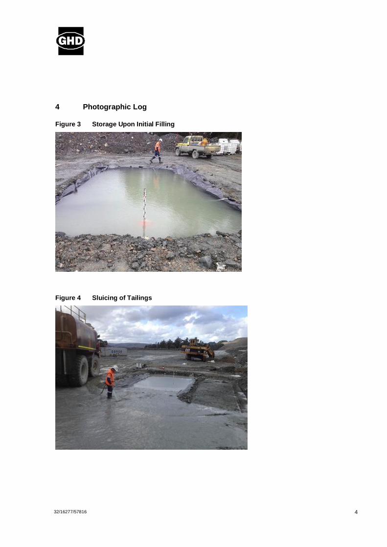
4
32/16277/57816
4 Photographic Log
Figure 3 Storage Upon Initial Filling
Figure 4 Sluicing of Tailings

5
32/16277/57816
Figure 5 Storage & Embankment
Figure 6 Embankment Partial Deconstruction
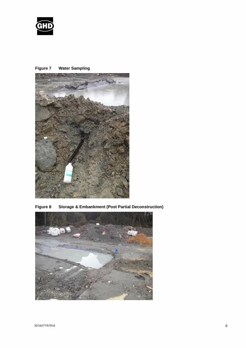
6
32/16277/57816
Figure 7 Water Sampling
Figure 8 Storage & Embankment (Post Partial Deconstruction)

7
32/16277/57816
Figure 9 Full Embankment Breach
5 Testing Results
5.1 Permeability
Estimations of the embankment material permeability were made by using the formula Q = kiA, where Q (m3/s) was determined through the rate the storage level dropped, A was the cross-sectional area of the
upstream face of the southern embankment below the water level, and i (hydraulic gradient) was estimated. As there was no seepage evident at the downstream toe, i was difficult to accurately
determine, but was thought to be in the range of 0.25 – 0.7. Table 1 shows the estimated permeability
results for the storage with no tailings.
Table 1 Permeability Results – No Tailings
Time Storage Level (mm)
Q (m3/s) k (m/s)
i = 0.25 i = 0.5 i = 0.7
10:12 530 - - - -
10:40 525 1.32 x 10⁻⁴ 1.92 x 10⁻⁴ 9.59 x 10⁻⁵ 6.85 x 10⁻⁵
12:10 508 1.39 x 10⁻⁴ 2.07 x 10⁻⁴ 1.04 x 10⁻⁴ 7.40 x 10⁻⁵
12:40 503 1.23 x 10⁻⁴ 1.87 x 10⁻⁴ 9.34 x 10⁻⁵ 6.67 x 10⁻⁵
Average 1.95 x 10⁻⁴ 9.76 x 10⁻⁵ 6.97 x 10⁻⁵

8
32/16277/57816
Upon sluicing tailings into the storage, the seepage rate expectedly reduced. The depth of tailings
against the embankment was found to be approximately 260 mm; Table 2 shows the permeability results obtained when taking the effective cross-sectional area as the entire upstream face, as well as reducing the area to account for tailings against the embankment.
Table 2 Permeability Results – With Tailings
Time Storage Level (mm)
Q (m3/s)
k (m/s): Full Face Cross-Sectional Area
k (m/s): Reduced Cross-Sectional Area
i = 0.25 i = 0.5 i = 0.7 i = 0.25 i = 0.5 i = 0.7
07:30 538 - - - - - - -
09:05 534 3.10 x 10⁻⁵ 4.45 x 10⁻⁵ 2.23 x 10⁻⁵ 1.56 x 10⁻⁵ 8.64 x 10⁻⁵ 4.32 x 10⁻⁵ 3.09 x 10⁻⁵
10:00 530 5.36 x 10⁻⁵ 7.75 x 10⁻⁵ 3.87 x 10⁻⁵ 2.77 x 10⁻⁵ 1.52 x 10⁻⁴ 7.58 x 10⁻⁵ 5.41 x 10⁻⁵
13:25 520 3.59 x 10⁻⁵ 5.27 x 10⁻⁵ 2.63 x 10⁻⁵ 1.88 x 10⁻⁵ 1.04 x 10⁻⁴ 5.22 x 10⁻⁵ 3.73 x 10⁻⁵
14:30 516 4.53 x 10⁻⁵ 6.73 x 10⁻⁵ 3.37 x 10⁻⁵ 2.40 x 10⁻⁵ 5.35 x 10⁻⁴ 6.76 x 10⁻⁵ 4.83 x 10⁻⁵
Average 6.05 x 10⁻⁵ 3.02 x 10⁻⁵ 2.16 x 10⁻⁵ 1.19 x 10⁻⁴ 5.97 x 10⁻⁵ 4.26 x 10⁻⁵
5.2 Laboratory Testing
5.2.1 Water Sampling Three water samples were taken from the deconstructed embankment, with both turbidity and total suspended solids (TSS) tested. The results are presented below.
Table 3 Water Sampling Laboratory Results
Sample I.D. Turbidity (NTU) TSS (mg/L)
SR 1 129 219
SR 2 70 65
SR 3 84 61
5.2.2 Material Grading A sample of the embankment material was graded in a laboratory, with the result presented in Figure 10.
It can be seen that the material falls within the grading envelope as specified in the Design Report.

9
32/16277/57816
Figure 10 Embankment Material Grading
6 Analysis of Results
6.1 Permeability
It can be seen that the initial estimated permeability of the Filter Face material ranged between 7.0 x 10⁻⁵
and 2.0 x 10⁻⁴ m/s, and the seepage through the front face decreased to a result in a permeability range of 2.2 x 10⁻⁵ to 6.1 x 10⁻⁵ m/s when tailings were introduced.
After accounting for the reduced effective area due to tailings deposition, the range of permeability was
found to be between 4.3 x 10⁻⁵ and 1.2 x 10⁻⁴ m/s, in line with the initial results.
6.2 Water Quality
The laboratory testing results were relatively high when compared to common EPA restrictions on tailings dam outflows (Grange do not have any specific limits in place for Turbidity nor TSS for their
MCTD, however operations try to keep the NTU below 40); however the results are considered reasonable given they were taken from approximately 1.5m of the upstream face, and the Filter Face has been designed with a minimum width of 10m. Furthermore, the results may have been influenced by
localised erosion due to the deconstruction of the embankment (in particular SR 1).

10
32/16277/57816
Visual observations within the embankment, during both partial deconstruction and full breaching, found
no evidence of tailings migration within the embankment. The seepage rate decreasing due to building up of tailings on the upstream face was also indicative of the Filter Face performing as designed.
7 Discussion
From the laboratory results and visual observations, it is considered that the A-Type waste rock, placed and compacted in 0.5m layers, is likely to function to prevent migration of tailings into the Flow-Through rock drain.
The design of the Filter Face found that for Stage 1 of the embankment (crest level RL 264m, Flow-Through rock drain maximum height RL 244m), there is a risk of overtopping during extreme flood events, or consistent wet weather periods, if the Filter Face permeability is less than 5 x 10⁻⁵ m/s. The
results from the testing found a range of 4.3 x 10⁻⁵ to 2.0 x 10⁻⁴ m/s, and so it cannot be confidently assumed that this design requirement will be met.
It should be noted that the consequences of such an event occurring would be to channel water flow over
the coarse rockfill flow-through drain (20m below the crest height), potentially causing some erosion and environmental issues, however it is not considered that the embankment would be at risk of failure or release of tailings.
It should also be noted that the effects of these extreme weather events is greatly reduced as the crest height increases, due to the drastically increased flood storage capacity. Due to the rapid construction period (the embankment is expected to be at full height after 18 months of construction), the risk of such
events on the Stage 1 embankment are considered minimal.
The embankment is essentially designed as a ‘leaky’ dam with no decant structure, and so a further impact of the Filter Face being lower permeability than the design is that the pond will rise with tailings
deposition, thereby hindering beach development at the upstream end of the storage. Again, this is expected to become less of a problem as the beach height increases due to the increased storage capacity. However, there are contingency’s in the design to account for this.
8 Conclusion
From the testing results and analysis presented above, it is not considered that any adjustments need to be made to the design of the proposed SDTSF at this stage. However, it is recommended that the testing program during the early stages of construction (as set out in the Design Report) be strictly adhered to,
and a review of the design be made during construction (through performance monitoring and design validation) to ensure it is not necessary to reduce the height of the Filter Face.
Regards
Andrew Simmons Civil Engineer

SDTSF
Slimes Embankment Trial
26 August 2012 Location of Trial Embankment
Construction of Trial Embankment Plastic over excavated and compacted base

Initial clay seal under main embankment
Upper plastic seal

Four pass compaction of western embankment
Six pass compaction of eastern embankment

Second layer placement of Main Embankment following 8 pass compaction of lower embankment
Completed Embankment
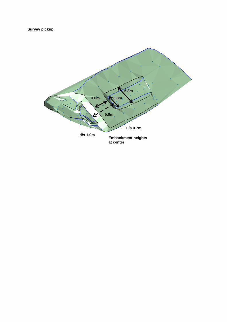
Survey pickup
3.8m 3.6m
5.8m
5.8m
d/s 1.0m
u/s 0.7m
Embankment heights at center

DEVELOPMENT PROPOSAL AND ENVIRONMENTAL MANAGEMENT PLAN South Deposit Tailings Storage Facility APPENDIX V Geotechnical Report SDTSF March 2013

Grange Resources Ltd
Report for South Deposit TSF Design
Geotechnical Investigation
June 2012

32/16277/57114 South Deposit TSF DesignGeotechnical Investigation
This Report for Savage River South Deposit TSF Design - Geotechnical Investigation (“Report”):
1. has been prepared by GHD Pty Ltd (“GHD”) for Grange Resources Limited;
2. may only be used and relied on by Grange Resources Limited;
3. must not be copied to, used by, or relied on by any person other than Grange Resources Limited without the prior written consent of GHD;
4. may only be used for the purpose of a Geotechnical Assessment for the South Deposit TSF Design (and must not be used for any other purpose).
GHD and its servants, employees and officers otherwise expressly disclaim responsibility to any person other than Grange arising from or in connection with this Report.
To the maximum extent permitted by law, all implied warranties and conditions in relation to the services provided by GHD and the Report are excluded unless they are expressly stated to apply in this Report.
The services undertaken by GHD in connection with preparing this Report:
� were limited to those specifically detailed in section 1.1 of this Report;
� did not include a) Any detailed seismic risk study; b) Any deep drilling to identify deeper rock defects; c) Detailed mapping of any active or former landslides over the site.
The opinions, conclusions and any recommendations in this Report are based on assumptions made by GHD when undertaking services and preparing the Report (“Assumptions”), including(but not limited to):
� conditions at the time of investigation do not differ under different weather conditions;
� the limited number of test sites represents conditions within and immediately surrounding the site(s);
� the referenced external information ( eg: geological maps ) show all know subsurface hazards over the site.
GHD expressly disclaims responsibility for any error in, or omission from, this Report arising from or in connection with any of the Assumptions being incorrect.
Subject to the paragraphs in this section of the Report, the opinions, conclusions and any recommendations in this Report are based on conditions encountered and information reviewed at the time of preparation and may be relied on until 24 months or if site conditions are altered, after which time, GHD expressly disclaims responsibility for any error in, or omission from, this Report arising from or in connection with those opinions, conclusions and any recommendations.

32/16277/57114 South Deposit TSF DesignGeotechnical Investigation
Contents
1. Introduction 1
1.1 Investigation Objectives 1 1.2 Scope of the Field Investigation 1
2. Results 3
2.1 Geology 3 2.2 Site Descriptions 3 2.3 Subsurface Conditions 3 2.4 Laboratory Testing 4 2.5 A Type Waste Rock Grading 4 2.6 Constant Head Permeameter Testing 6
3. Geotechnical Assessment 7
3.1 TSF Abutment Foundation 7 3.2 Sediment Trap Foundations 7 3.3 Potential Borrow 8 3.4 Waste Rock Filling 8
4. Conclusions & Recommendations 9
4.1 South Dump TSF 9 4.2 Construction Materials 9
Table IndexTable 1 Summary of Subsurface Conditions at proposed
TSF Abutment 4 Table 2 Summary of Subsurface Conditions at proposed
Sediment Trap 4 Table 3 Summary of laboratory Results 4 Table 4 Summary of Constant Head Permeameter Test 6 Table 5 Waste Rock Parameters 9

32/16277/57114 South Deposit TSF DesignGeotechnical Investigation
Figure IndexFigure 1 Site G1 5 Figure 2 Site G2 5 Figure 3 Site G3 6
AppendicesA Site Plan B Site Geology C Test Pit/Exposure Logs D Laboratory Test Reports E In Situ Permeameter Results F Photographic Record G Standard Notes

132/16277/57114 South Deposit TSF DesignGeotechnical Investigation
1. Introduction
Grange Resources Ltd (Grange) has engaged GHD to undertake a geotechnical investigation for aproposed Tailing Storage Facility (TSF) near the existing South Deposit Pit at the Savage River mine, North West Tasmania. The investigation entailed subsurface investigations near the northern or rightabutment (facing downstream) and for a sediment trap downstream of the proposed TSF. Sampling of existing A Type waste rock near to the site was also undertaken along with permeability testing of the existing Main Creek Tailings Dam (MCTD) wall. The permeameter testing was undertaken to estimate design parameters for the proposed TSF which will be constructed using similar mine derived A Type materials.
GHD have undertaken previous investigations at the Savage River Mine which include a recent investigation for raising the existing Main Creek Tailings Dam (MCTD) detailed in ’MCTD Raise to RL338m Geotechnical Investigation’ GHD, April 2012. Earlier geotechnical reports have also beenundertaken on the MCTD, detailed in ‘MCTD Raise to RL333m Geotechnical Investigation’ GHD, October 2009.
This report details the findings from the most recent geotechnical investigation conducted during June 2012.
1.1 Investigation ObjectivesThe objectives of the GHD geotechnical investigation were as follows:
� Investigate and assess the subsurface conditions near the proposed northern abutment for suitability as a foundation for the proposed dam wall;
� Investigate and assess the subsurface conditions near the proposed sediment trap for suitable foundations;
� Investigate and assess the subsurface conditions above the proposed TSF for suitable clay core materials:
� Assess the suitability of the existing mine waste rock for dam wall construction, and
� Undertake in-situ permeability testing of the existing rock fill and clay in the existing MCTD to provide design parameters for the proposed TSF.
1.2 Scope of the Field InvestigationThe field investigation was undertaken by a senior geotechnical engineer between the 5th and 7th of June 2012. The site plan given in Appendix A shows the locations of the field testing. The geotechnical program consisted of:
� Digging test pits with a 25 tonne excavator at 3 locations to identify any suitable borrow areas for TSF core material;
� Logging of existing excavations & rock exposures near the proposed TSF southern abutment;

232/16277/57114 South Deposit TSF DesignGeotechnical Investigation
� Digging test pits/Logging exposures with a 25 tonne excavator at the location of a proposed sediment trap;
� Sampling waste rock materials at 3 locations to determine suitability for TSF construction;
� Undertaking 5 Constant Head Permeameter tests in the existing MCTD A Type rockfill to assess design parameters for the main components of the proposed TSF at South Deposit;
� Collection of bulk soil samples for laboratory testing and reference; and
� Recording of observations during field investigations, including photographing subsurface conditions and waste rock samples.

332/16277/57114 South Deposit TSF DesignGeotechnical Investigation
2. Results
2.1 GeologyAccording to the Mineral Resources Tasmania (MRT), 1:250,000 Geological Map of northwest Tasmania, the surface geology over the investigation site(s) consists of Tertiary Basalt to the northern part and the Arthur Metamorphic Complex** to the south of the site(s). The natural materials encountered are consistent with this geology at the TSF site. Alluvial soils were also identified at the sediment trap site (3216277-6).
** (Cambrian Metamorphic Chloritic Schist, minor Phyllite, Dolomite & Magnesite).
An extract from the MRT geological map showing the proposed structures is given in Appendix B along with a copy of Granges Regional Geology survey map.
2.2 Site Descriptions
2.2.1 South Deposit TSF
The proposed South Deposit TSF will be located east of the existing South Deposit mine pit and southfrom the existing South Dump. The area grades from the ridge down to a gully (creek) becoming moderately steep with heavy vegetation. The slope(s) have numerous large trees with minor undergrowth and thick organics on the ground surface. Numerous small undulations indicate shallow older landsides have occurred over the entire steeper slopes, however there is no visible evidence of any recent large head scarps or debris toes. Rock outcrops/cuttings logged during the investigation indicate colluvium (landslide material) exists over the deeper rock in the upper slopes.
Site drainage is very poor.
2.2.2 Sediment Trap
The proposed sediment trap site is located in a narrow gully near the confluence of two creeks. The existing creek has a steep bank to the east and a roadway to the west, which is cut into the existing hillside, which climbs steeply to the west. There are numerous logs and timbers scattered over and inthe creek. The existing cutting indicates a boundary between residual clays and alluvial soils associated with the creek running from the west.
Site drainage is poor.
2.3 Subsurface ConditionsDetailed test pit/exposure logs are given in Appendix C. A summary of subsurface conditions encountered at the proposed TSF and Sediment Trap site are given in the tables below:

432/16277/57114 South Deposit TSF DesignGeotechnical Investigation
Table 1 Summary of Subsurface Conditions at proposed TSF Abutment
Depth Range (m) Subsurface Description
0.00-1.00 SILTY CLAY, trace gravel(angular)- colluvium
0.90-1.80 SILTY CLAY, ( residual )
1.80-3.00 BASALT(HW-MW), irregular clay filled joints
0.00-1.40 SCHIST/SANDSTONE(HW-SW), tight cleavage
Table 2 Summary of Subsurface Conditions at proposed Sediment Trap
Depth Range (m) Subsurface Description
0.00-1.80 FILL, SILTY CLAY, gravel, logs, stumps
0.00-2.80 SILTY CLAY, ( colluvium )
1.80-3.80 SILTY CLAY ( residual )
2.40-3.80 CLAYEY GRAVEL, coarse grained
2.4 Laboratory TestingAvailable soil samples were sent to ADG laboratories for simple classification testing. The test report sheets are given in Appendix D.
A summary of the test results (excluding the grading results) are given in Table 3 Summary of laboratory ResultsTable 3
Table 3 Summary of laboratory Results
SAMPLE LOCATION
DEPTH (m)
Liquid Limit (%)
Plastic Limit (%)
Plasticity Index (%)
Moisture Content (%)
3216277-2 0.5 – 0.7 NA Non Plastic NA 63.6
3216277-10 1.5 – 1.7 33- 25 8 27.2
2.5 A Type Waste Rock GradingThree sites were sampled to assess the Particle Size Distribution (PSD) of existing mine waste rock which will be utilised in the proposed TSF design. The PSD of the rock has been assessed using a method described by Professor David Williams ( University of Queensland ) where the materials retained on a 19mm sieve are separated and weighed on site and a photograph of this material spread on a tarpaulin is utilised to assess the PSD of this ‘oversize’ material. The materials passing the 19mm sieve were sent to ADG laboratory for analysis using methods given in AS1289. Results of these conventional

532/16277/57114 South Deposit TSF DesignGeotechnical Investigation
PSD assessments are given in Appendix D.
The PSD of the oversize fraction of the waste rock samples is also presented in Appendix D, along with the combined PSD of the samples.
The photographs of the 3 oversize samples are shown in Figures 1 to 3 below:
Figure 1 Site G1
Figure 2 Site G2

632/16277/57114 South Deposit TSF DesignGeotechnical Investigation
Figure 3 Site G3
2.6 Constant Head Permeameter TestingIn Situ constant head permeameter tests were undertaken at 4 locations on the downstream A Type rockfill material at the Main Creek Tailings Dam (MCTD) and a single test (PT – 5 ) was undertaken on the upstream clay materials*. The plots of the in situ testing are given in Appendix E. The results of the testing are summarised in Table 4.
Table 4 Summary of Constant Head Permeameter Test
Test Location PT -1 PT - 2 PT - 3 PT - 4 PT - 5*
Permeability (m/s) 7.0 x 10⁻⁶ 4.2 x 10⁻⁴ 2.0 x 10⁻⁶ 7.1 x 10⁻⁵ 2.0 x 10⁻⁶

732/16277/57114 South Deposit TSF DesignGeotechnical Investigation
3. Geotechnical Assessment
3.1 TSF Abutment Foundation The investigation in the abutment areas was limited due to poor access and further verification of the ground conditions are recommended to be undertaken during TSF construction to confirm the assumptions within this report.
The four investigation areas undertaken in the vicinity of the northern abutment of the proposed TSFindicates a surface geology of Proterozoic Schistose Sandstone/Schist in the upper flank with Tertiary Basalts down lower in the valley (refer to photographic Record in Appendix F). The deeper gully areas have not been investigated, and silts or deeper formations associated with old river courses should be anticipated in this area. Faulting along the gully course is not evident, however this possibility, along with the possibility of deep creek defects, should be investigated once the location of the dam wall is finalised.
Some evidence of hillside movements (shallow landslides) is evident over the Tertiary Basalts. This underlying rock appears competent with irregular jointing not critical for stability in the hillside location. The Schist exposure higher up the slope appears massive with limited jointing and cleavage orientated in a favourable angle for the abutment stability. Given the older Schist is situated up slope from the Basalt, a near vertical boundary is anticipated between these two test locations.
The opposite southern abutment area has not been investigated. The geological map does not show Tertiary Basalt (& scree) in this vicinity. A surface geology of schist/phyllite is shown to exist on the southern flank of the valley, and if rock is also massive with similar orientated cleavage as the northern flank, then this area would be favourable as a foundation for the proposed TSF.
3.2 Sediment Trap FoundationsThe sediment trap will be constructed in a gully with an existing creek and roadway downstream from the confluence with another creek from the west. At the time of writing, an option of constructing two traps,one in each of the creeks near this location, is likely rather than a single larger trap.
The existing creek is located in recent fill, overlying alluvial silts, with deeper soft transported clays beneath the silts. An existing road cutting adjacent to the site shows colluvium (landslide deposits) overlying a near vertical boundary between deep alluvium (gravels) and also residual basaltic clays. Atest pit to the eastern flank of the gully also encountered colluvium (landslide deposits) which overly the creek banks.
This area will require stripping through all the alluvium and excavating into residual clays or possibly onto competent rock (schist/phyllite), which can be anticipated at greater than 2.2m below the existing creek bed. Confirmation of foundations is required during construction.

832/16277/57114 South Deposit TSF DesignGeotechnical Investigation
3.3 Potential BorrowPits 3216277-1 to 3216277-3 encountered some residual clay’s over the parent basalt rock, which ranges in weathering from highly to moderately weathered. Given the limited depth of clays and the variability in depth to rock (and weathering), the volume of clay material in this vicinity is considered too limited and unreliable for use in the TSF core. The residual clay in the vicinity has good properties for construction of a clay core.
3.4 Waste Rock FillingThe waste rock materials encountered in the 3 sample locations (G1-G3) appear to be well graded.Although there appeared to be some variability in the dumps, the sampled material particle size distributions appear reasonably consistent.
The waste rock appears to be of volcanic or metamorphic origin, and is slightly weathered to fresh. This rock has a high strength and thus is not expected to degrade significantly if utilised as a construction material. The good grading will result in good compaction if used as an embankment material.

932/16277/57114 South Deposit TSF DesignGeotechnical Investigation
4. Conclusions & Recommendations
4.1 South Dump TSFThis investigation indicates the northern abutment is likely to be suitable for the proposed TSF dam and further investigations areas required both in the gully and southern abutment area. During further investigations, engineering parameters of each formation should be measured. For initial designs, we recommend the following rock engineering parameters:
BASALT (HW-MW) Density: 23 – 27 kN/m3
Rock Modulus: 1000 – 3000 MPa
Angle of Internal Shearing: 36 - 390
SCHIST/SCHISTOSE SANDSTONE (SW)
Density: 22 – 24 kN/m3
Rock Modulus: 10,000 – 40,000 MPa
Angle of Internal Shearing: 39 - 410 (30-340 along cleavage)
4.2 Construction Materials
4.2.1 Clay Core
As indicated above, there is suitable clay to the north of the proposed TSF, but insufficient volumes. We note there are others area of the site where current excavations are removing suitable clays for the construction of a clay core.
4.2.2 Waste Rock
The following mechanical properties are suggested for the design of embankments using the waste rock identified at the 3 samples sites (G1-G3):
Table 5 Waste Rock Parameters
Surcharge (kPa)
Density (kN/m3)
Angle of Internal Shearing (0)
Angle of Dilation (00)
100 19- 40- 2
750 21- 45 5

32/16277/57114 South Deposit TSF DesignGeotechnical Investigation
Appendix A
Site Plan

"D"D"D
"D"D#0
"D
#V
#D*"D
16277_9
16277_8
16277_7
16277_616277_5
16277_4
16277_3
16277_2
16277_1
16277_10
200
250
300
350
150
350
200
150
300
250
200
200
250
150
250
350
150
200
150
250
300
200
200
150
200
150
200
250
250
350
150
200
250
250
350
200
150
250
250
200150
200
150
300
250
300
200
200
150
250
200
250
150
200
250
200
200
200
250
200
250
300
250
150
150
200
300
200
200
150
250
150
250
200
250
300
200
200
250
150
250
300
200
200
150
200
250
250
250
250
150
200
250
150
200
200
200
200
200
250
350
200
300
250
300
200
200
300
350
300
350
350
150
200
200
350
300
150
300
300
250
150
250
250
200
150
200
350
200
250
250
150
250
350
300
250
250
150
200
200
200
200
250
200
300
200
250
300
250
150
250
250
200
250
200
200
200
200
200
200
150
200
150
250
150
250
200
300
200
150
300
150
300
200
250
200
200
250
150
25030
0250
300
150
200
200
150
250
250
250
200
250 250
200
300
200
200
250
200
200
350
250
150
200
250
250
250
300
250
250
200
200
300
200
200
200
250350
350
300
350
250
250
150
250
250
200
250
300
300
200
300
200
200300
300
250
300
200
200
250
150
150
350
250
200
200
250250
250
150
250200
300
300
150
150
250
200
200
300
200
200
150
150
250
300
250
250
200
250
300
300
200
250
200
250
300
150
250
300
250
200
250
300
300
300
350250
200
250
250
300
150
300
300
250
200
200150
200
150
200
350
200
350
200
150
250
250
200
250
250
250300250
150
250
300
200
250
300
200
150
250
200
150
250
300
200
300
250
250
250
300
250
250
150
250
300
300
200
300
250
350
200
200
250
250
300
150
250
250
250250
150
200
250
200
300
200
250
150
250
150
200
250
200
300
300
250
150
200
250
200
300
200
200
250
250
250
250
300
250
250 30
0
200
200
300
250
350
150
150
250
200
300
200
250
250
300
150
300
300
250
250
150
150
150
15030
0
250
150
250
150
250
300
300
250
300
300
250
250
250
250
300
200
300
300
250
350
250
200
250
200
150
200
300
350
250
200
200
250
200
150
250
150
250
250
200
250200
250
250
250
300
250
200
250
250
200
250
300
200
250
150
150
300
250
250
300
150
200
300
300
200
200
150
200
150
150
200
200
300
200
200
250
250
300
250
250
200
200
200 250
250
250
200
200
300
250
250
300
200
350
150
348,000
348,000
349,000
349,000
5,402
,000
5,402
,000
5,403
,000
5,403
,000
G:\32\16277\GIS\Maps\3216277_002_Geotech_SitePlan.mxd
0 40 80 120 160 200
Metres
Map Projection: Transverse MercatorHorizontal Datum: GDA 1994Grid: GDA 1994 MGA Zone 55 o
© 2012. Whilst every care has been taken to prepare this map, GHD (and DPIPWE) make no representations or warranties about its accuracy, reliability, completeness or suitability for any particular purpose and cannot accept liability and responsibility of any kind (whether in contract, tort or otherwise) for any expenses, losses, damages and/or costs (including indirect or consequential damage) which are or may be incurred by any party as a result of the map being inaccurate, incomplete or unsuitable in any way and for any reason.
Grange Resources (Tasmania) P/LTSF/WRD Invest & Design Geotech Investigation
Appendix A
Job NumberRevision 0
32-16277 21
06 Jul 2012
Site Plan
Date
Data source: GHD geotech sites, dam design, roads, contours 2012, DPIPWE imagery 2003. Created by: jpulford
2 Salamanca Square Hobart TAS 7000 Australia T 61 3 6210 0600 F 61 3 6210 0601 E [email protected] W www.ghd.com
Paper Size A3
LEGEND
"D Test Pit
#D* Existing Cutting (Test Pit)
#0 Existing Cutting
#V Existing Exposure
Dam Design
Existing Roads
Contours (10 m)

32/16277/57114 South Deposit TSF DesignGeotechnical Investigation
Appendix B
Site Geology

"D"D"D
"D"D#0
"D
#V
#D*"D
16277_9
16277_8
16277_7
16277_616277_5
16277_4
16277_3
16277_2
16277_1
16277_10
Lac
TbLaa
Lat
348,000
348,000
349,000
349,000
5,402
,000
5,402
,000
5,403
,000
5,403
,000
G:\32\16277\GIS\Maps\3216277_003_Geotech_Geology.mxd
0 40 80 120 160 200
Metres
Map Projection: Transverse MercatorHorizontal Datum: GDA 1994Grid: GDA 1994 MGA Zone 55 o
© 2012. Whilst every care has been taken to prepare this map, GHD (and DPIPWE and MRT) make no representations or warranties about its accuracy, reliability, completeness or suitability for any particular purpose and cannot accept liability and responsibility of any kind (whether in contract, tort or otherwise) for any expenses, losses, damages and/or costs (including indirect or consequential damage) which are or may be incurred by any party as a result of the map being inaccurate, incomplete or unsuitable in any way and for any reason.
Grange Resources (Tasmania) P/LTSF/WRD Invest & Design Geotech Investigation
Appendix B
Job NumberRevision 0
32-16277 21
06 Jul 2012
Geology
Date
Data source: GHD geotech sites, dam design, roads, contours 2012, DPIPWE imagery 2003, MRT 1:250,000 geology 2008. Created by: jpulford
2 Salamanca Square Hobart TAS 7000 Australia T 61 3 6210 0600 F 61 3 6210 0601 E [email protected] W www.ghd.com
Paper Size A3
LEGEND
"D Test Pit
#D* Existing Cutting (Test Pit)
#0 Existing Cutting
#V Existing Exposure
Dam Design
Existing Roads
1:250,000 Geology
Tertiary basalt
Arthur Metamorphic Complex
~~ ~ Laa - Amphibolite
~~ ~ Lac - Chloritic schist, with minor phyllite, dolomite and magnesite
Lat - Quartz-mica schist, quartzite, phyllite and rare dolomite(geological boundaries are approximate)

?
?
?
?
?
?
?
Aeromagnetic Peak21,601nT
?
?
?
?
?
?
?
?
??
??
?
?
?
?
?
?
?
?
?
?
??
??
???
?
?
?
??
?
?
?350
350
350
350
350
350
300
300
300
300
300
300
250
250
250
250
250
250
250
250
250
250
250
250
200
200
200
200
200
200
200
200
200
200
200
200
200
150
150
150
150
150 150
150
150
150
150
150
150
150
150
150
150
150150
150
150
150
150
150
150
100100
100
100
100
100
100
100
100
100
100
50
50
50
5040
4030
350
350
350
350
350
350
300
300
300
300
300
300
250
250
250
250
250
250
250
250
250
250
250
250
200
200
200
200
200
200
200
200
200
200
200
200
200
150
150
150
150
150 150
150
150
150
150
150
150
150
150
150
150
150150
150150
150
150
150
150
150
100100
100
100
100
100
100
100
100
100
100
100
50
50
50
5040
4030
200
62
70
GC1
PMIFlow-Through
Dam
70
83
68
72
82
83
88
83
87
73
78
65
35
CENTREPIT
NORTH
72
75
65
3
15
25
58
55
3018
35
50
Pipelin
e
MBO (T)
SAQ
6870
60
87
80
78
83
65
45
MBO (T)
60
88
85
80 60
SAQ(Very thin)
85
SwitchMain
85
70
5828
75
The Gap
BC
1C
onve
yor
CR
US
HE
RG
UL L
YD
UM
PS
Cut
Crusher
80
80
83
ZOO
ZOO
Coveredby waste
Roa
d
Pit
Acce
ss
SXW gf,ly+ SXQ
MXCab,p; etc
Shor
t
ZOO
ZOO
ZOO
ZOOZOX
ZOX
?
?
ASQ
OXH+ MXC
OXCab,py,ly; etc
SRW + MBOmt
Land Slip
Faul
t
Wes
tern
Bou
ndar
y
ZOO
MXB; etc
85
8074
75
55
35
40
80
80
80
85
65
70
75
VMO
MDB, etc
SRW
SRW
SRW
SRW+ MBOmt
OXH+ MXC OXC
ab,py,ly; etc
VMO
MXR+ MXB
MXR+ MXB
MXCab,p; etc Core Yard
MXCab,p; etc
ZOO
ZOO
MDB, etc
MDB, etc
Main RiverCrossing
Flooded pit isthe long term
settlement pond
Flooded
WesternRiver
Crossing
Covered by backfill
72
77
85
Land Slip
ZOX
ZOX
ZOO
ZOO
ZOX
Slip
LandZOO
ZOO
ZOO
ZOO
UPPER ROM
'A' DUMP
MXCab,p; etc
MXR
East
ern
Contac
t
Faul
tLand
Slip
OXCab,py,ly; etc
MDB,etc
OXH+ MXC
88
60
70
?
MDB, etc
83
79
?
?Ea
ster
nCo
ntac
tFa
ult
?
90
40
MXR
MXR
GRF
ZOO
SOUTHERN DEPOSIT
MRBfg,etc
WesternEastern
Lens
87
85
OXCab,py,ly; etc
MXCab,p;etc
MBO (T)
MBO (T)
MBO (T)
MBO (T)
MBO (T)
Mainly residualsoil cover
ZOO
MBO (T)
SAQ
'B' DUMP
Buried TertiaryBasalt contact
Low order groundmagnetic anomaly
CENTRE PITSOUTHERNEXTENSION
Wes
tern
Boun
dary
Faul
t
SOUTH DUMP
OXCab,py,ly;etc
MRBfg,etc
SRW
Ridg
e
Lefro
y
Faul
t
85
65
90
78
Land Slip
Plant, Administrationand Maintenance
76
MBO (T)
LEASEBOUNDARY
SOUTH WESTDUMP
EMERGENCYTAILINGS DAM
Iron
Mai
den
Faul
t
Lens
OXCab,py,ly; etc
GRF
MRBfg,etc
MBO (T)
SAQ
80 80
85
6040
72
87
87
3085
15
30
85
78
87
60
86
8082
80
76
85
85
75
8580
8787
82
3631
40
437565
8169
8180
8372
55
70 80
80
Clay
Dum
p
SXWgf,lySXQly
MDBsw,lm,cy
Chevron folds
Increasingalluvium
SXWgf,ly
SXWgf,ly
SXQly
SXQly
Interbanded SXWgf,ly + SXQly
SXWgf,ly
SXWgf,ly
SXQly
? Toppled ?
Gol
den
Rid
ge
Obsidian
Creek
SXWgf,ly
SXWgf,lySXQly
uwuw
Isoclinalfolds infoliation
mw
uw
uw
Main
Creek
SXWgf,lySXQ
SXWgf,ly
SXQly
uw
MXR
Reclaim Pond
ETDW
estern Outlet
Under Construction
Water sheddingcover
Dolomite Dam
Dolomite Dam
Alkaline flowthrough dump
Upper
South
-Wes
t Dum
p -
Pote
ntial
lyAcid
Form
ingW
aste
South DepositCrib Hut
Lookout
Towns
ends
Creek
Old School
River
Township
OXCab,py,ly;etc
86
83
OXCab,py,ly;etc
CENTREPIT
SOUTH
SOUTH LENSSTOCKPILE
SOUTHLENS
PIT
Alka
line
side
hill c
over
Proposed tailingsdam outflow
LEASEBOUNDARY
Yard
85
87
85
55
78
80
55
50
82
62
65
75
78
75
8530
60
75
72
87
64
35
85
67
65
7720
68
7087 87
35
73
41
76
78
70
40
8565 68
75
67
76
39
61
45
68
44
80
47
7438
80
70
70
70
70 55
50
82
80
75
85
50
75
34
68
75
59
5463
77
53
60
60
77
80
87 81
57
74
87
73
70 80
85
80
70
85
8565
?
? OXH+ MXC
OXH+ MXC
PillowedBasalt
Multiple cross-cuttingdykes
Covered by backfill
?
?
MXCab,p;etc
MXCab,p;etc
?
?
?
?
?
?
Savage
Displaced
Savage
Broderick Creek
drai
nage
Sava
geRi
ver
Savage
Riv
er
River
SXWab,gf
MultipleLodes
'Unit 20'Lode
Side
rite
Faul
t
?
6000E
7000E
NORTH PIT PROJECTAustralian Bulk Minerals SURVEY DETAILS
Savage River Mine
Base map derived from ABM's topographic data for December, 2004. Centre Pit North andSouth Lens Pit are shown though these pits are respectively back-filled with waste and flooded.The Slot is partly back-filled with waste.Geological mapping by Nic Turner, January 2005 - January 2006, with compilation of previous workfrom South Lens Pit (Thornett, 1999), Centre Pit North and South (Thornett and Turner 2002), NorthPit (Totino, 2002), South Pit (Turner, 2003) and Centre Pit Southern Extension (Urquhart, 1966).Grade control data have been used in the delineation of the main iron ore bodies.Cartography by Gillian Bennett, October - November 2005, February - June, 2006.
REGIONAL GEOLOGY (SOUTH)
NORTH(mine,grid)
AMGNORTH
NORTH(mag)
10.3°
1.85°
EW
S
0 100 200 300 400 500m
SCALE 1:5000
CONTOUR INTERVAL 10m
12.15°
2006
6000E
7000E
8000N
7000N
6000N
5000N
4000N
5000E
6000N
5000N
8000N
7000N
4000N
5 405 000N
5 404 000N
350000E
349000E
348000E
5 406 000N
350000E
349000E
82
Aeromagnetic Peak
20,983nT
Geological boundary; approximate; inferred.
?? Shear zone or fault; inferred.
Foliation with direction and value of dip; vertical;coplanar foliation and metamorphic banding.
85 Joint with direction and value of dip; vertical.
Topographic lineament.
Linear aeromagnetic anomaly. Mineral Resources Tasmania data.
Aeromagnetic peak with value in nano Teslas.
SYMBOLSSee 1:1000 maps for key to letter symbols
82
85Fold hinge-direction of plunge and value.
Mine Lease Boundary.
SHEET INDEX
6 900 mN
7 770 mN
PITSOUTH
3 900 mN
CENTRE PIT
CENTRE PITSOUTHERNEXTENSION
4 700 mN
NORTHCENTRE PIT
SOUTH
6 000 mN
7 830 mN
Sheet 1
LENS PITSOUTH
Sheet 2NORTH PIT
NORTH PIT
8 380 mN
9 200 mN
10 500 mN
REGIONAL GEOLOGY (NORTH)
1:5000
1:1000
1:1000
1:1000
1:1000
1:1000
1:1000
1:1000
MINE LEASE BOUNDARY
250 Topographic Contour.
Pit Crest.Pit Toe.
(incomplete)
Planned North Pit Extenison.
BasaltMBO (T)
Terti
ary
Weakly indurated, carbonaceous mudstone (SAM);gravel with mainly quartzose detritus (SAQ)
ROCK UNITS
SAM, SAQ
ASQ Alteration (post-schistosity) consisting of siderite ± quartz ± pyrite.? Devonian
Waste dumps; ore stockpiles.Disturbed
SRW Ahrberg Group:Mainly foliated metasiltstone of very low metamorphic grade with metasandstone,graphitic and pyritic slate and dolomitic metasiltstone (SRW); magnetite-bearingmetabasalt (MBOmt) present.
Neoproterozoic
Fulfords Creek Muscovite Schist:Muscovite-albite-quartz schist ± graphite, with minor metaconglomerate. Sedimentaryorigin.
Mega Ramp Schists:Chlorite-albite schist ± pyrite ± porphyroblastic albite (MXC);chlorite-muscovite-albite schist ± porphyroblastic albite (OXH).Minor intervals of muscovite schist and quartz schist indicatesedimentary origin.
MXC; OXH
Box Cut Carbonate Assemblage:Boudinaged, blocky, massive magnesite (ORM) with interbandedchlorite schist (MXC). Blocky, massive dolomite (ORL). Thinly bandeddolomite-chlorite-muscovite schist (OXR) with lenses of muscoviteschist, micaceous quartz schist and graphitic schist that indicate asedimentary origin.
Main Host Assemblage:Boudinaged, blocky, massive, mafic rocks including fine grained, extrusiveand intrusive types (MRBfg), metadolerite (MDB) and uncommonmetagabbro (MGB). All comprise of actinolite-chlorite-albite-epidote-sphene± pyrite ± magnetite ± hematite. Massive rocks are gradational to blockyrocks with strong mineral alignment (MXB) and chlorite schist withanastomising foliation (MXCan). Dominant rock type varies with locality.Minor talc schist and serpentinite are locally present. Boudins and layers ofmagnesite and dolomite occur in the eastern host assemblage at SouthDeposit.
OXCab,lyWestern Wall Banded Schists:Flaggy schists with 1-20mm metamorphic layering of felsic and maficminerals parallel to foliation. Mainly chlorite-albite schist ± actinolite ±hornblende ± blue amphibole ± pyrite ± magnetite ± talc ± quartz. Abundantalbite suggests alteration while massive, mafic boudins and rafts probablyrepresent protolith. Intervals rich in felsic bands are present and may beassociated with minor tonalite. A substantial lens of granitoid (GRF )occurs at South Deposit. Minor schistose and massive magnetite ore present(ZOX, ZOO ).
Talc Schists:Comprise talc schist ± carbonate ± chlorite ± serpentine ± quartz ± whitemica ± magnetite ± pyrite,with subordinate serpentine schist and minormassive serpentinite.
Magnetite Ore:Grade ranging 15-100% DTR and unspecified mineralogy (ZOO)though mostly serpentinitic and/or pyritic.
Eastern Wall Carbonate-Mafic Assemblage:Boudinaged, blocky, massive magnesite (VMO), with vein style relationshipsat 8260mN,6640mE. Chlorite-carbonate-albite schist ± blue amphibole(MXR) that is fine grained with strong mineral alignment at North Pit thoughthe principal parting surfaces are subplanar joints. Strong foliation is theprincipal parting surface elsewhere. Carbonate may be disseminated or formveinlets. Also, sparse to common, relatively thin intervals of bandedcarbonate of uncertain origin occur as indicated ( ). Carbonatediminishes east of the River Dump. Boudins of MRBfg occur widely andanastomising seams of black, graphitic phyllonite (after mudstone) arecommon in MXR at South Deposit. Boudins and layers of magnesite anddolomite are common in the eastern host assemblage at South Deposit.
MXRMXB
Armstrong Creek Mafic Schists:Chlorite-albite schist characterised by 1-2mm, rounded, albiteporphyroblasts and interbanded with MXB, MRBfg, MDB, OXH.
MXCab,p; etc
Oonah Formation:Muscovite-quartz schist ± graphite with metamorphic banding parallel tofoliation(SXWgf,ly); schistose micaceous quartzite (SXQ). Sedimentary origin.
SXWgf,ly;
Cam
bria
n M
etam
orph
ics
(Neo
prot
eroz
oic
Prot
olith
s ?)
LEGEND
MRBfgMDBMGBMXB
MXCan
SXWab,gf
ORMORLMXC
Bow
ry C
reek
For
mat
ion
Water quality monitoring station.
VMO
1:5000
REGIONAL GEOLOGY(SOUTH)
SXQ
8530 Antiform; synform; each with direction of plunge and value
ZOO
OXR
MAINCREEK
TAILINGSDAM
UXT

32/16277/57114 South Deposit TSF DesignGeotechnical Investigation
Appendix C
Test Pit/Exposure Logs

������������ ������������������������������� �� ������� ��������������������������
�������������� ����!�� �������� ��������������
���� ����"#���� ����� �$�<=��>�[ ��
�]
�]
^
^
`{"
|�<=
$�<=
}}~|�=�}�
�
��
����� ���
����
����������������������
�������������!����"�#�
�!"�#�� ��$����&����"�#� ��"�"�#�
^��
� ��
��
��>�
���
��
��
!���
�
`��
[���
����
��++�#���/���;��"�#�
��[
����
����
��
���
�
�������}"��������� ��� �������������[���� ������������>
�������}"�������������������� ��� ������ �������� ���� �
����� <��&�=������
"#�� ������ ���
>�/�@�Q
���
���
���!
���
����
!���
>�#
���
=��=���|
�
|
$
�
�
��&��@�Q������Z�[�
����
����
��
��
���
[���
���
�� �
�������#�������������������"!������//��;"��"�#�\�/��"����������"��"�#�
�����
�]������^&���!���"`��&�zz���/{�
�����"�!������"��"�#
�#
^��
$�<$�<�=�"����=|$���=�{
`�{`"��"�����"�
��`"����"�
{���]��"��������]���^}
`"
���
"�
��}
����$
|��|
���|
��}
�`}
���`
]�
�`"
���
"^
}�
�"�`
���
����
���|
=��|������������������]���� ��������===���� ������������$��|�=�=�==�����������$��|�=�=�=����"�������������>������{�����{`��`"��"�]{�����"{`�{""����{���`"���`����

������������������������������� ��������������� ���������������������������������������� �
������������������������ �������������������� ������ ��� ������������������������������� ��
�� ����������������������� ������
��
��
�
�
���
����
����
��
�
����� ��!
����
����������������������
�������������!����"�#�
�!"�#�� ��$����&����"�#� ��"�"�#�
���
����
���������
"�
��#
���
�������
����
��++�#���/���;��"�#�
���
�$���
�� ��
�
!
�%�����&��������������������� ������� �������������������
�%�'���&�������������������(����������������������������
����� <��&�=������
����������������
>�/�@�Q
���
�����
�#�$
�
���#
�����
���
�)$�)$!�
!
�
�
�
*
��&��@�Q������Z���
���
�� �
+���
�� ���
,�����
�������#�������������������"!������//��;"��"�#�\�/��"����������"��"�#�
�����
�]������^&���!���"`��&�zz���/{�
�����"�!������"��"�#
��
�-�
����.�������*����.!����
���������%"����
����������
�%"����-��%+��%"��� "�&
��%/��
���&
������!)�..0�/�&
��&1�
��� /��%/���&
���
��
���!2$)$!�
=�������� ������3������������������.��������������4��)!���)�!���)������54��)!���)�!���)�!����4����� ���6������ �%��"���������%���������������������� ����%�%�����

���������������������������������������� ����
������������� ��������������
����������
�� ���
���
����
�
����� ���
����
����������������������
�������������!����"�#�
�!"�#�� ��$����&����"�#� ��"�"�#�
�������
�������
�
��!����
�� ��
�"����
��++�#���/���;��"�#�
#����
�$�%&
�'�����
�
�(��������"���������"����������"�������%�����' �
&(�)������"�������� ���*�����"������ �������������
����� <��&�=������
� ����"+
>�/�@�Q
�����"!
�$#���!
����,
�&�
�-$�.$�/
�
��&��@�Q������Z��" ��
�%�'
� ���
� ����
0����
�������#�������������������"!������//��;"��"�#���/��"����������"��"�#�
�����
���������&���!���"���&������/��
�����"�!������"��"�#
�,
�1�
2�3��4������4��2�/�����
�&����&��( &���
�5���&�5�&
�1��(���( ���# ��
��(6��
����
����2/�./--�/6�����
�����#6��(6����
�����#
���/�$.$�/
=��/�� � � " ��7� ������ ����� ��-�������� �� �8��.��2�./����.�������8��.��2�./����.������8���� � ��9����"���(�� ���������(�����������������&����#����(�(�����
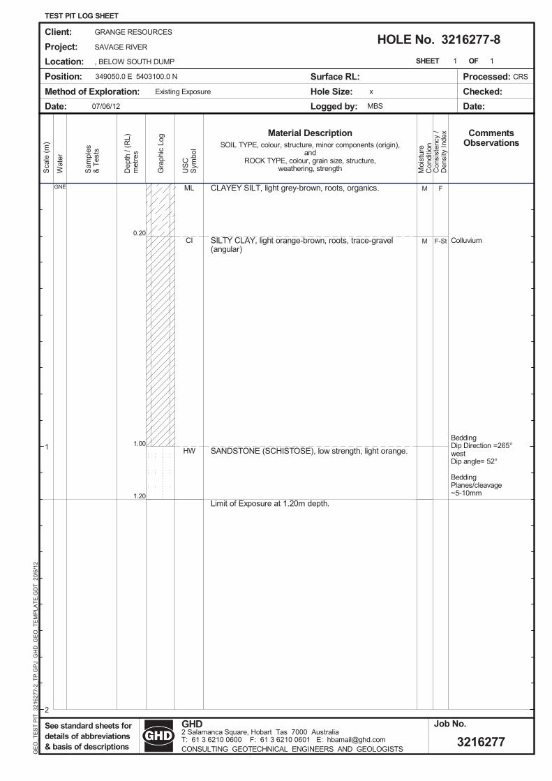
��������������������!�������������� �"�
������������������ ��������������� "���� ���% ��� �'
��#��(���%������(��'�������������������� ���
����������,������ ����/���������
���������
1�����#���#���"����:/.4;���#��� ���:�4/;
1������� �$"�� � ���4�����
��
��
��
�
�
���
��/�
����
��/�
�
����
����� ���
����
����������������������
�������������!����"�#�
�!"�#�� ��$����&����"�#� ��"�"�#�
�������
�������
�
��!����
�� ��
�"����
��++�#���/���;��"�#�
#����
�$�%&
�'�����
�
�(��������"���������"����������"�������%�����' �
&(�)������"�������� ���*�����"������ �������������
����� <��&�=������
�,������,�����
>�/�@�Q
�����"!
�$#���!
����,
�&�
�-$�.$�/
�
/
��&��@�Q������Z��" ��
�%�'
� ���
� ����
0����
�������#�������������������"!������//��;"��"�#���/��"����������"��"�#�
�����
���������&���!���"���&������/��
�����"�!������"��"�#
�,
�1�
2�3�4�������4��2�������
�&����&��( &���
�5���&�5�&
�1��(���( ���# ��
��(6��
����
����2/�./--�/6�����
�����#6��(6����
�����#
���/�$.$�/
=��/�� � � " ��7� ������ ����� ��-�������� �� �8��.��2�./����.�������8��.��2�./����.������8���� � ��9����"���(�� ���������(�����������������&����#����(�(�����

�<=>�?@�AB������������������� ���������������������������������������������� ������ ������������� ��������� ���������������
�����������������������������
��������
������ �������� !"����#������$!"
�%&'(
����
����� ���
����
����������������������
�������������!����"�#�
�!"�#�� ��$����&����"�#� ��"�"�#�
)����� �
��������
*��
��
+��
& ���
������
��++�#���/���;��"�#�
�����
�,��-��
�� ��
�
�./��012(������� ���� ���� ������ ������������� ��������
-.�3�012(������� ��� ������4����� ���� �������� ������� �����
����� <��&�=������
(5��������������
>�/�@�Q
�����������
�,�������
�/��5
�-�
�6,�7,�8
�
8
��&��@�Q������Z������
���
%���
��
����
��0����
�������#�������������������"!������//��;"��"�#�\�/��"����������"��"�#�
�����
�]������^&���!���"`��&�zz���/{�
�����"�!������"��"�#
�5
)��
9� �6����(��!��87 7���'
&-#'&(�-(�.*-�(�
�#:#&(�-/:(-
#�*0)('0��.*0;���0�<���(�.%��.*0;��*)2
&(.=0
(�0�2/0
��98�7866
�8=0
2�&2>�
�&;�=&
(.=0
()2�#
0(�&�0�
�� ,7,�8
=��8�����������?�� ���;�+� ���0����6�����#��� ����0@��7��9�78����7������<@��7��9�78����7�����(@���+�����������.'�*�0/'&��&(.0(�;'/�#���('&/'((-���#'���&(.�.&/�0�

����������������������78��� �8������������������� ��������������� �
����������������������
������������ ���������������� �������������������������� � ���������������
��� ��������������������������������� �����������������������������������
���������������������� ����������
�������!�����������
��!��" ����������
��
�#
#�
��
�
�
$%�
��!�
&�'�
��&�
���
(()&'�*(�
��
��
����� ��&
����
����������������������
�������������!����"�#�
�!"�#�� ��$����&����"�#� ��"�"�#�
��� �
��
���������
+�
����
���
$����
�����
��++�#���/���;��"�#�
,���
�-��"
�����
&
�.�����(�������� �������������������� ������������
".�/���(�������������� �0� ��������������� ������
����� <��&�=������
��� ������������
>�/�@�Q
��� � ���
�-,� ���
�����
�"�
��-�1-&�
&
�
��&��@�Q������Z����
����
����
���
��
2�� �
�������#�������������������"!������//��;"��"�#�\�/��"����������"��"�#�
�����
�]������^&���!���"`��&�zz���/{�
�����"�!������"��"�#
��
���
�!& 1����������1� ���%
$"%$��"��.+"���
�3$��"�3�"
�.+�#�,�(.������4����.���.+�#�,+�(
$�.5�
��
��(
���� �&1�
����5�
(�$(6�
�$#,5$
�.5�
��(
���
�$,
���&!-1-&�
=��������������7����#��������� ��������� �������8��1&� �1�&���1������48��1&� �1�&���1�&����8���������9�������.%�+���%$��$�.���#%������%$�%��"���%,��$�.�.$����

:;<=>=�?@;A���������������� ���������������������������������� ��������� ���������������
���������������������������������������������� ����!"#$""����� ������%� �����������������������������������������������������%�
����������������������������������
�������������&��
������� ���� ������'�("��
)*�*+)*
),
*,
),
))
-./"�("
"�$"
!�0"
1�2"
'�("
33#��
����� ��(
����
����������������������
�������������!����"�#�
�!"�#�� ��$����&����"�#� ��"�"�#�
)������
���������
4��
�%�
���
-�� ��
����
��++�#���/���;��"�#�
5� ��
�+�67�8
�����
(
�9�����:/�������������������������� ������6������8����
79�;���:/����������������<������������������������������
����� <��&�=������
599��.�5=�!$$
>�/�@�Q
�������%
�+5����%
�����>
�7�
"2+"2+(!
(
!
1
'
$
��&��@�Q������Z����
�6�8
,����
���
��
?����
�������#�������������������"!������//��;"��"�#���/��"����������"��"�#�
�����
���������&���!���"���&������/��
�����"�!������"��"�#
�>�0"",��4�;/�
)��
1'@@$0�"�/��$'"1"00�"�.
-7�.-/�7/�947�/�
��A�-/�7�A/7
���/�9,��94�*�54):
-/9B�
/���:��
��1!(2!CC#!B�
:�-:D�
�-*5B-
/9B�
/):��
�/�-5��
�(0+2+(!
=��!�����������E������*�����������C"""�����������F��2(�1�2!("�"2""����3F��2(�1�2!("�"2"(���/F���������G�������9.�4���.-��-/9�/�*.������/.-�.//7����.5��-/9�9-����

97-�.����������&��%�� ��������������������������������������#������
�����������������������������������%����� �����($"#1""����������������#����������%�(�'"#(�$"��������� ���� ����,�������
(�@"������������������%��������������%� �������������������������
������� � ������1�""��
:��*
),
,)
�//:�-/
"�("
(�!"
(�@"
1�""
::�(1"�:�
A���
����� ��(
����
����������������������
�������������!����"�#�
�!"�#�� ��$����&����"�#� ��"�"�#�
)������
���������
4��
�%�
���
-�� ��
����
��++�#���/���;��"�#�
5� ��
�+�67�8
�����
(
�9�����:/�������������������������� ������6������8����
79�;���:/����������������<������������������������������
����� <��&�=������
599��.�5=�!$$
>�/�@�Q
�������%
�+5����%
�����>
�7�
"2+"2+(!
(
!
1
'
$
��&��@�Q������Z����
�6�8
,����
���
��
?����
�������#�������������������"!������//��;"��"�#���/��"����������"��"�#�
�����
���������&���!���"���&������/��
�����"�!������"��"�#
�>�0"",��4�;/�
)��
1'@@!$�"�/��$'"1(((�"�.
-7�.-/�7/�947�/�
��A�-/�7�A/7
���/�9,��94�*�54):
-/9B�
/���:��
��1!(2!CC#!B�
:�-:D�
�-*5B-
/9B�
/):��
�/�-5��
�(0+2+(!
=��!�����������E������*�����������C"""�����������F��2(�1�2!("�"2""����3F��2(�1�2!("�"2"(���/F���������G�������9.�4���.-��-/9�/�*.������/.-�.//7����.5��-/9�9-����

97-�.�����������������������������������%�������������������������������������#���������������
���������������������������������������� �����%� ������������ �����'"#'""��������������������%�����������������������������#�������������%� �����
������� �:������!�@"��
9��*
),
))
-./"�("
"�0"
!�@"
�3#��
����� ��(
����
����������������������
�������������!����"�#�
�!"�#�� ��$����&����"�#� ��"�"�#�
)������
���������
4��
�%�
���
-�� ��
����
��++�#���/���;��"�#�
5� ��
�+�67�8
�����
(
�9�����:/�������������������������� ������6������8����
79�;���:/����������������<������������������������������
����� <��&�=������
599��.�5=�!$$
>�/�@�Q
�������%
�+5����%
�����>
�7�
"2+"2+(!
(
!
1
'
$
��&��@�Q������Z�����
�6�8
,����
���
��
?����
�������#�������������������"!������//��;"��"�#���/��"����������"��"�#�
�����
���������&���!���"���&������/��
�����"�!������"��"�#
�>�0"",��4�;/�
)��
1'@C$(�"�/��$'"1((@�"�.
-7�.-/�7/�947�/�
��A�-/�7�A/7
���/�9,��94�*�54):
-/9B�
/���:��
��1!(2!CC#!B�
:�-:D�
�-*5B-
/9B�
/):��
�/�-5��
�(0+2+(!
=��!�����������E������*�����������C"""�����������F��2(�1�2!("�"2""����3F��2(�1�2!("�"2"(���/F���������G�������9.�4���.-��-/9�/�*.������/.-�.//7����.5��-/9�9-����

��������������������������������&��������������6�������8�����������������������������������������������������6���������%����������8����������
������� �:������!�!"��
����������������
�����&����6��������8
�* )-./
"�($
!�!"
��
����� ��(
����
����������������������
�������������!����"�#�
�!"�#�� ��$����&����"�#� ��"�"�#�
)������
���������
4��
�%�
���
-�� ��
����
��++�#���/���;��"�#�
5� ��
�+�67�8
�����
(
�9�����:/�������������������������� ������6������8����
79�;���:/����������������<������������������������������
����� <��&�=������
599��.�5=�!$$
>�/�@�Q
�������%
�+5����%
�����>
�7�
"2+"2+(!
(
!
1
'
$
��&��@�Q������Z�����
�6�8
,����
���
��
?����
�������#�������������������"!������//��;"��"�#���/��"����������"��"�#�
�����
���������&���!���"���&������/��
�����"�!������"��"�#
�>�0"",��4�;/�
)��
1'@'""�"�/��$'"!1C(�"�.
-7�.-/�7/�947�/�
��A�-/�7�A/7
���/�9,��94�*�54):
-/9B�
/���:��
��1!(2!CC#!B�
:�-:D�
�-*5B-
/9B�
/):��
�/�-5��
�(0+2+(!
=��!�����������E������*�����������C"""�����������F��2(�1�2!("�"2""����3F��2(�1�2!("�"2"(���/F���������G�������9.�4���.-��-/9�/�*.������/.-�.//7����.5��-/9�9-����

3�����������������������������#��������������&��������
������������� �
�����������������#���%�����������������
!�C"#!�@"���*��&%��� ���� ��������6����8������� �:������!�@"��,��������� ��
�*
�*
)
#
,
�//:�-/
(�2"
(�@"
!�@"
3
#
�
����� ��(
����
����������������������
�������������!����"�#�
�!"�#�� ��$����&����"�#� ��"�"�#�
)������
���������
4��
�%�
���
-�� ��
����
��++�#���/���;��"�#�
5� ��
�+�67�8
�����
(
�9�����:/�������������������������� ������6������8����
79�;���:/����������������<������������������������������
����� <��&�=������
599��.�5=�!$$
>�/�@�Q
�������%
�+5����%
�����>
�7�
"2+"2+(!
(
!
1
'
$
��&��@�Q������Z|����
�6�8
,����
���
��
?����
�������#�������������������"!������//��;"��"�#���/��"����������"��"�#�
�����
���������&���!���"���&������/��
�����"�!������"��"�#
�>�0"",��4�;/�
)��
1'@10"�"�/��$'"!1C(�"�.
-7�.-/�7/�947�/�
��A�-/�7�A/7
���/�9,��94�*�54):
-/9B�
/���:��
��1!(2!CC#!B�
:�-:D�
�-*5B-
/9B�
/):��
�/�-5��
�(0+2+(!
=��!�����������E������*�����������C"""�����������F��2(�1�2!("�"2""����3F��2(�1�2!("�"2"(���/F���������G�������9.�4���.-��-/9�/�*.������/.-�.//7����.5��-/9�9-����

32/16277/57114 South Deposit TSF DesignGeotechnical Investigation
Appendix D
Laboratory Test Reports

0.0
10.0
20.0
30.0
40.0
50.0
60.0
70.0
80.0
90.0
100.
0 0.01
0.1
110
100
1000
%Passing
Siev
e Si
ze (m
m)
Was
te R
ock
Com
bine
d PS
D
G1 G2 G3

���������������� ������������������������������������ ������ !"!"�##$�%���� !"!"� �&'��"()�!(#
������ ���*��+��� ������� ���������������� ����������*��+����� ������*���� �������,��������-�, �������,�������, �������*��,����,����.������� ����������������� �!��*��, � "���������*���'� ����#$
/����
0�1��,0���� %���&�'��(
������0���� �
���������2�,�% �0����������3��� � ������� ���� ����
4������&������ � �����������5�6���� �����
���)����������*���*������
7��,�����������,�������,����8���'�7�9�����,���������1��������:�����,���,.�����*������8���2�;�2<&�"�!(: �**��-�,��������� ,����.���
604���,����0�=;/�7;/>�&&/<627�72;''�� "(!
�!�)?*,?�!�
����3���
��� +.��������
���,���,,����-�,
+
+
�:�:!
�:�:�
+
!:�
�:��
�: ��
#:"(
�:#!(
+
+
! :(
�)
+
+
��
+
�:#:�
�:!:�
+
+
+
+
+
+
+
+
�����3
+
+
����
+
+
):(
:"
!:�:�
�: :�
"(
�":(
�:���
�:�(��:�"(
������������
7��4����,
$�����)
7��,����*����
��:!

���������������� ������������������������������������ ������ !"!"�##$�%���� !"!"� �&'��"()�!(#
������ ���*��+��� ������� ���������������� ����������*��+����� ������*���� �������,��������-�, �������,�������, �������*��,����,����.������� ����������������� �!��*��, � "���������*���'� ����,-
/����
0�1��,0���� %���&�'��(
������0���� �
���������2�,�% �0����������3��� � ������� ���� ����
4������&������ �� �����������5�6���� �����
���)����������������*���*
7��,�����������,�������,����8���'�7�9�����,���������1��������:�����,���,.�����*������8���2�;�2<&�"�!(: �**��-�,��������� ,����.���
604���,����0�=;/�7;/>�&&/<627�72;''�� "(!
�!�)?*,?�!�
����3���
��� +.��������
���,���,,����-�,
+
+
�:�:!
�:�:�
+
!:�
�:��
�: ��
#:"(
�:#!(
+
+
! :(
�)
+
+
��
+
�:#:�
�:!:�
+
+
+
+
+
+
+
+
�����3
+
+
����
+
+
):(
:"
!:�:�
�: :�
"(
�":(
�:���
�:�(��:�"(
������������
7��4����,
$�����)
7��,����*����
��:!

���������������� ������������������������������������ ������ !"!"�##$�%���� !"!"� �&'��"()�!(#
������ ���*��+��� ������� ���������������� ����������*��+����� ������*���� ������*,��������-�, �������,�������, �������*��,����,����.������� ����������������� �!��*��, � "���������*���'� ����,.
/����
0�1��,0���� %���&�'��(
������0���� �
���������2�,�% �0����������3��� � ������� ���� ����
4������&������ �� )����������5�6���� �����
���)��������)���*��������
7��,�����������,�������,����8���'�7�9�����,���������1��������:�����,���,.�����*������8���2�;�2<&�"�!(: �**��-�,��������� ,����.���
604���,����0�=;/�7;/>�&&/<627�72;''�� "(!
�!�)?*,?�!�
����3���
��� +.��������
���,���,,����-�,
+
+
�:�:!
�:�:�
+
!:�
�:��
�: ��
#:"(
�:#!(
+
+
! :(
�)
+
+
��
+
�:#:�
�:!:�
+
+
+
+
+
+
+
+
�����3
+
+
����
+
+
):(
:"
!:�:�
�: :�
"(
�":(
�:���
�:�(��:�"(
������������
7��4����,
$�����)
7��,����*����
��:!

32/16277/57114 South Deposit TSF DesignGeotechnical Investigation
Appendix E
In Situ Permeameter Results

GHD www.ghd.com.auTel. (03) 6210 0600 Fax. (03) 6223 8246
162 Macquarie St HOBART Tas 7000
PT-1G:\32\12594\1259400\Tech\Field Permeability 12-02-2009.xls6/07/2012 3:39 PM Page 1 of 1
CONSTANT HEAD PERMEABILITY TEST REPORT
GRANGE RESOURCES LTDSavage River MCTD
Job No 32/16277 Site No PT - 1Date 08-Jun-12 Depth of Hole 45 cm
Location Downslope Rock face Depth of Water in Hole 35 cmOperator MBS Average Radius of Hole 5 cm
ReadingNo.
Time(min)
Water Mark(L)
Water Used(L)
Q(mL/min)
Ksat(cm/min)
Ksat(m/s)
0 0 6.5 0.01 3.7 6.0 0.5 137.0 0.05 8.11E-062 5.9 5.5 0.5 222.2 0.08 1.32E-053 9.6 5.0 0.5 136.4 0.05 8.08E-064 13.7 4.5 0.5 122.5 0.04 7.25E-065 17.3 4.0 0.5 138.1 0.05 8.18E-066 21.2 3.5 0.5 125.9 0.04 7.46E-067 25.2 3.0 0.5 127.6 0.05 7.55E-068 29.3 2.5 0.5 119.9 0.04 7.10E-069 33.4 2.0 0.5 122.5 0.04 7.26E-0610 37.7 1.5 0.5 117.6 0.04 6.97E-0611 41.74 1 0.5 122.55 0.04 7.26E-0612 45.99 0.5 0.5 117.65 0.04 6.97E-06
y = -1E-06ln(x) + 1E-05
0.00E+00
2.00E-06
4.00E-06
6.00E-06
8.00E-06
1.00E-05
1.20E-05
1.40E-05
1 2 3 4 5 6 7 8 9 10 11 12
Perm
eabi
lity
(m/s
)
Reading No.
PT - 1 In Situ Permeability Plot

GHD www.ghd.com.auTel. (03) 6210 0600 Fax. (03) 6223 8246
162 Macquarie St HOBART Tas 7000
PT-2G:\32\12594\1259400\Tech\Field Permeability 12-02-2009.xls6/07/2012 3:39 PM Page 1 of 1
CONSTANT HEAD PERMEABILITY TEST REPORT
GRANGE RESOURCES LTDSavage River MCTD
Job No 32/16277 Site No PT - 2Date 07-Jun-12 Depth of Hole 35 cm
Location Crest of Rock face Depth of Water in Hole 20 cmOperator MBS Average Radius of Hole 5 cm
ReadingNo.
Time(min)
Water Mark(L)
Water Used(L)
Q(mL/min)
Ksat(cm/min)
Ksat(m/s)
0 0 6.5 0.01 0.75 6.0 0.5 666.7 0.54 8.94E-052 1.00 5.5 0.5 2000.0 1.61 2.68E-043 1.75 5.0 0.5 666.7 0.54 8.94E-054 2.08 4.5 0.5 1515.2 1.22 2.03E-045 2.33 4.0 0.5 2000.0 1.61 2.68E-046 2.50 3.5 0.5 2941.2 2.37 3.94E-047 2.66 3.0 0.5 3125.0 2.51 4.19E-048 2.82 2.5 0.5 3125.0 2.51 4.19E-049 2.98 2.0 0.5 3125.0 2.51 4.19E-0410 3.14 1.5 0.5 3125.0 2.51 4.19E-0411 3.30 1 0.5 3125.0 2.51 4.19E-0412 3.46 0.5 0.5 3125.0 2.51 4.19E-04
y = -3E-06x2 + 7E-05x + 2E-05
0.00E+00
5.00E-05
1.00E-04
1.50E-04
2.00E-04
2.50E-04
3.00E-04
3.50E-04
4.00E-04
4.50E-04
5.00E-04
1 2 3 4 5 6 7 8 9 10 11 12
Perm
eabi
lity
(m/s
)
Reading No.
PT - 2 In Situ Permeability Plot

GHD www.ghd.com.auTel. (03) 6210 0600 Fax. (03) 6223 8246
162 Macquarie St HOBART Tas 7000
PT-3G:\32\12594\1259400\Tech\Field Permeability 12-02-2009.xls6/07/2012 3:40 PM Page 1 of 1
CONSTANT HEAD PERMEABILITY TEST REPORT
GRANGE RESOURCES LTDSavage River MCTD
Job No 32/16277 Site No PT - 3Date 05-Jun-12 Depth of Hole 35 cm
Location Crest of Rock face Depth of Water in Hole 20 cmOperator MBS Average Radius of Hole 5 cm
ReadingNo.
Time(min)
Water Mark(L)
Water Used(L)
Q(mL/min)
Ksat(cm/min)
Ksat(m/s)
0 0 6.5 0.01 2.66 6.0 0.5 188.0 0.15 2.52E-052 5.25 5.5 0.5 193.1 0.16 2.59E-053 7.83 5.0 0.5 193.8 0.16 2.60E-054 10.58 4.5 0.5 181.8 0.15 2.44E-055 13.66 4.0 0.5 162.3 0.13 2.18E-056 16.99 3.5 0.5 150.2 0.12 2.01E-057 21.41 3.0 0.5 113.1 0.09 1.52E-058 25.83 2.5 0.5 113.1 0.09 1.52E-059 30.83 2.0 0.5 100.0 0.08 1.34E-0510 39.25 1.5 0.5 59.4 0.05 7.96E-0611 50.17 1.2 0.3 27.5 0.02 3.68E-06
y = -2E-07x2 + 2E-07x + 3E-05
0.00E+00
5.00E-06
1.00E-05
1.50E-05
2.00E-05
2.50E-05
3.00E-05
1 2 3 4 5 6 7 8 9 10 11
Perm
eabi
lity
(m/s
)
Reading No.
PT - 3 In Situ Permeability Plot

GHD www.ghd.com.auTel. (03) 6210 0600 Fax. (03) 6223 8246
162 Macquarie St HOBART Tas 7000
PT-4G:\32\12594\1259400\Tech\Field Permeability 12-02-2009.xls6/07/2012 3:40 PM Page 1 of 1
CONSTANT HEAD PERMEABILITY TEST REPORT
GRANGE RESOURCES LTDSavage River MCTD
Job No 32/16277 Site No PT - 4Date 05-Jun-12 Depth of Hole 65 cm
Location Crest of TSF Rock Face Depth of Water in Hole 35 cmOperator MBS Average Radius of Hole 5 cm
ReadingNo.
Time(min)
Water Mark(L)
Water Used(L)
Q(mL/min)
Ksat(cm/min)
Ksat(m/s)
0 0 6.5 0.01 0.42 6.0 0.5 1201.9 0.43 7.12E-052 0.83 5.5 0.5 1207.7 0.43 7.15E-053 1.25 5.0 0.5 1190.5 0.42 7.05E-054 1.66 4.5 0.5 1219.5 0.43 7.22E-055 2.08 4.0 0.5 1190.5 0.42 7.05E-056 2.50 3.5 0.5 1201.9 0.43 7.12E-057 2.92 3.0 0.5 1187.6 0.42 7.03E-058 3.34 2.5 0.5 1182.0 0.42 7.00E-059 3.75 2.0 0.5 1210.7 0.43 7.17E-0510 4.17 1.5 0.5 1199.0 0.43 7.10E-0511 4.59 1 0.5 1190.5 0.42 7.05E-0512 5.00 0.5 0.5 1219.5 0.43 7.22E-05
y = -6E-08ln(x) + 7E-05
6.85E-05
6.90E-05
6.95E-05
7.00E-05
7.05E-05
7.10E-05
7.15E-05
7.20E-05
7.25E-05
1 2 3 4 5 6 7 8 9 10 11 12
Perm
eabi
lity
(m/s
)
Reading No.
PT - 4 In Situ Permeability Plot

GHD www.ghd.com.auTel. (03) 6210 0600 Fax. (03) 6210 0601
2 Salamanca Square, HOBART Tas 7000
PT-5G:\32\12594\1259400\Tech\Field Permeability 12-02-2009.xls6/07/2012 3:40 PM Page 1 of 1
CONSTANT HEAD PERMEABILITY TEST REPORT
GRANGE RESOURCES LTDSavage River MCTD
Job No 32/16277 Site No PT - 5Date 05-Jun-12 Depth of Hole 45 cm
Location Upstream Clay Core Depth of Water in Hole 35 cmOperator MBS Average Radius of Hole 5 cm
ReadingNo.
Time(min)
Water Mark(L)
Water Used(L)
Q(mL/min)
Ksat(cm/min)
Ksat(m/s)
0 0.00 6.5 0.01 2.08 6.0 0.5 240.4 0.09 1.42E-052 3.17 5.5 0.5 458.7 0.16 2.72E-053 4.33 5.0 0.5 431.0 0.15 2.55E-054 7.00 4.5 0.5 187.3 0.07 1.11E-055 9.75 4.0 0.5 181.8 0.06 1.08E-056 13.58 3.5 0.5 130.5 0.05 7.73E-067 17.41 3.0 0.5 130.5 0.05 7.73E-068 22.33 2.5 0.5 101.6 0.04 6.02E-069 28.41 2.0 0.5 82.2 0.03 4.87E-0610 44.58 1.5 0.5 30.9 0.01 1.83E-0611 62.08 1.2 0.3 17.14 0.01 1.02E-06
y = 4E-05e-0.277x
0.00E+00
5.00E-06
1.00E-05
1.50E-05
2.00E-05
2.50E-05
3.00E-05
3.50E-05
1 2 3 4 5 6 7 8 9 10 11
Perm
eabi
lity
(m/s
)
Reading No.
PT - 5 In Situ Permeability Plot

32/16277/57114 South Deposit TSF DesignGeotechnical Investigation
Appendix F
Photographic Record

116277/57114
Site 3216277-1
Site 3216277-2

216277/57114
Site 3216277-3
Site 3216277-4

316277/57114
Site 3216277-5
Site 3216277-6
(Site 3216277-7 not recorded)

416277/57114
Site 3216277-8
Site 3216277-9

516277/57114
Site 3216277-10

32/16277/57114 South Deposit TSF DesignGeotechnical Investigation
Appendix G
Standard Notes

GENERAL NOTES
The report contains the results of a geotechnical investigation conducted for a specific purpose and client. The results should not be used by other parties, or for other purposes, as they may contain neither adequate nor appropriate information. In particular, the investigation does not cover contamination issues unless specifically required to do so by the client.
TEST HOLE LOGGING The information on the test hole logs (boreholes, test pits, exposures etc.) is based on a visual and tactile assessment, except at the discrete locations where test information is available (field and/or laboratory results). The test hole logs include both factual data and inferred information. Moreover, the location of test holes should be considered approximate, unless noted otherwise (refer report). Reference should also be made to the relevant standard sheets for the explanation of logging procedures (Soil and Rock Descriptions, Core Log Sheet Notes etc.).
GROUNDWATERUnless otherwise indicated, the water levels presented on the test hole logs are the levels of free water or seepage in the test hole recorded at the given time of measuring. The actual groundwater level may differ from this recorded level depending on material permeabilities (i.e. depending on response time of the measuring instrument). Further, variations of this level could occur with time due to such effects as seasonal, environmental and tidal fluctuations or construction activities. Confirmation of groundwater levels, phreatic surfaces or piezometric pressures can only be made by appropriate instrumentation techniques and monitoring programmes.
INTERPRETATION OF RESULTS
The discussion or recommendations contained within this report normally are based on a site evaluation from discrete test hole data, often with only approximate locations (e.g. GPS). Generalised, idealised or inferred subsurface conditions (including any geotechnical cross-sections) have been assumed or prepared by interpolation and/or extrapolation of these data. As such these conditions are an interpretation and must be considered as a guide only.
CHANGE IN CONDITIONSLocal variations or anomalies in the generalised ground conditions do occur in the natural environment, particularly between discrete test hole locations. Additionally, certain design or construction procedures may have been assumed in assessing the soil-structure interaction behaviour of the site. Furthermore, conditions may change at the site from those encountered at the time of the geotechnical investigation through construction activities and constantly changing natural forces.
Any change in design, in construction methods, or in ground conditions as noted during construction, from those assumed or reported should be referred to this firm for appropriate assessment and comment.
GEOTECHNICAL VERIFICATION
Verification of the geotechnical assumptions and/or model is an integral part of the design process - investigation, construction verification, and performance monitoring. Variability is a feature of the natural environment and, in many instances, verification of soil or rock quality, or foundation levels, is required. There may be a requirement to extend foundation depths, to modify a foundation system and/or to conduct monitoring as a result of this natural variability. Allowance for verification by appropriate geotechnical personnel must be recognised and programmed for construction.
FOUNDATIONS
Where referred to in the report, the soil or rock quality, or the recommended depth of any foundation (piles, caissons, footings etc.) is an engineering estimate. The estimate is influenced, and perhaps limited, by the fieldwork method and testing carried out in connection with the site investigation, and other pertinent information as has been made available. The material quality and/or foundation depth remains, however, an estimate and therefore liable to variation. Foundation drawings, designs and specifications should provide for variations in the final depth, depending upon the ground conditions at each point of support, and allow for geotechnical verification.
REPRODUCTION OF REPORTSWhere it is desired to reproduce the information contained in our geotechnical report, or other technical information, for the inclusion in contract documents or engineering specification of the subject development, such reproductions must include at least all of the relevant test hole and test data, together with the appropriate Standard Description sheets and remarks made in the written report of a factual or descriptive nature.
Reports are the subject of copyright and shall not be reproduced either totally or in part without the express permission of GHD.
GHD GEOTECHNICS Specialist Services in Geotechnical Engineering, Geology, Field/Laboratory Testing and Hydrogeologywww.ghd.com.au/ghdgeotechnics
Ref
: D
S5.5
.1
Issu
e 1.
5 D
ate:
04/
06/2
008

GLOSSARY OF SYMBOLS GHD GEOTECHNICS Specialist Services in Geotechnical Engineering, Geology, Field/Laboratory Testing and Hydrogeologywww.ghd.com.au/ghdgeotechnics
This standard sheet should be read in conjunction with all test hole log sheets and any idealised geological sections prepared for the investigation report. GENERAL Symbol Description Symbol Description
D Disturbed Sample PZ Piezometer Installation U Undisturbed Sampled (suffixed by sample size or R Rising Head Permeability Test tube diameter in mm if applicable) F Falling Head Permeability Test C Core Sample (suffixed by diameter in mm) PBT Plate Bearing Test SV Shear Vane Test (suffixed by value in kPa) Water Inflow (make) SPT Standard Penetration Test (with blows per 0.15m) Water Outflow (loss)
N SPT Value Temporary Water Level HB SPT hammer bouncing Final Water Level PM Pressuremeter Test Point Load Test (axial) PP Pocket Penetrometer (suffixed by value in kPa) Point Load Test (diametric)
PK Packer Test IMP Impression Device Test
SOIL SYMBOLS Main Components
SAND CLAY SILT
GRAVEL FILL TOPSOIL
Ref
: DS
6.5.
1 I
ssue
1.6
D
ate:
20/
11/2
008
Minor Components
sandy clayey silty
gravelly vegetation, roots
Note: Natural soils are generally a combination of constituents, e.g. sandy CLAY ROCK SYMBOLS Sedimentary Igneous
SANDSTONE SHALE GRANITIC ROCK
CLAYSTONE CONGLOMERATE IGNEOUS DYKE
SILTSTONE COAL BASALTIC ROCK
Note: Additional rock symbols may be allocated for a particular project.
NATURAL FRACTURES (Coding)
Fracture Type Orientation JT Joint For vertical non-oriented core ... “Dip” angle (eg. 5°) measured relative to horizontal BP Bedding Plane For inclined non-oriented core ... “Angle” measured relative to core axis. Cb Cross Bed For inclined oriented core ... “Dip” angle and “Dip Direction” angle (eg. 45°/225° mag.)SS Sheared Surface SM Seam VT Vertical CS Crushed Seam HZ or 0° HorizontalFZ Fragmented Zone d degrees SZ Shear Zone VN Vein Infilling or Coating Shape Roughness OthersCN Clean PLN Planar POL Polished DIS Discontinuous X Carbonaceous CU Curved SLK Slickensided OP Open CLAY Clay UN Undulating SO Smooth Cl Closed KT Chlorite ST Stepped RF Rough TI Tight CA Calcite IR Irregular VR Very Rough FE Iron Oxide MI Micaceous Mn Manganese Py Pyrite QZ Quartz VE Veneer

SOIL DESCRIPTION
This procedure involves the description of a soil in terms of its visual and tactile properties, and relates to both laboratory samples and field exposures as applicable. A detailed soil profile description, in association with local geology and experience, will facilitate the initial (and often complete) site assessment for engineering purposes. The method involves an evaluation of each of the items listed below and is in general agreement with both Australian Standard AS 1726 (the Site Investigation Code) and ASTM D2487 and D2488. MOISTURE The moisture condition of the soil is most applicable for cohesive soils as a precursor to the assessment of consistency and workability. The moisture condition is described as:-
Dry (dusty, dry to the touch) Slightly Moist Moist (damp, no visible water) Very Moist or Wet (visible free water, saturated condition)
In addition, the presence of any seepage or free water is noted on the testhole logs. COLOUR Colour is important for correlation of data between testholes and during subsequent excavation operations. The prominent colour is noted, followed by (spotted, mottled, streaked etc.) then secondary colours as applicable. Colour is usually described at as-received moisture condition, though both wet and dry colours may also be appropriate. CONSISTENCY / DENSITY INDEXThis assessment is based on the effort required to penetrate and/or mould the soil, and is an indicator of shear strength. Granular soils are generally described in terms of density index as listed in AS 1726. These soils are inherently difficult to assess and normally a penetration test procedure (SPT, DCP or CPT) is used in conjunction with published correlations. Alternatively, in-situ density tests can be conducted in association with minimum and maximum densities performed in the laboratory.
Term Symbol Density Index (%)
Very Loose VL < 15 Loose L 15 - 35Medium Dense MD 35 - 65Dense D 65 - 85Very Dense VD >85
Cohesive soils can be assessed by direct measurement (shear vane, CPT etc), or estimated approximately by tactile means and/or the aid of a geological pick as given on the following table. It is emphasised that a “design shear strength” must take cognisance of the mode of testing and the in-situ moisture content with the possible variations of moisture with time.
Term Symbol Tactile Properties Undrained Strength Su(kPa)
Very Soft VS Extrudes between fingers when squeezed in hand <12
Soft S Easily penetrated by thumb about 30-40 mm. Pick head can be pushed in up to shaft. 12-25
Firm F Penetrated by thumb 20-30mm with moderate effort. Sharp end of pick pushed in 30-40mm.
25-50
Stiff St Indented by thumb about 5mm with moderate effort. Pick pushed in up to 10mm. 50-100
Very Stiff VSt Readily indented by thumb nail. Slight indentation produced by pushing pick into soil. 100-200
Hard H Difficult to indent with thumb nail. Requires power tools for excavation. >200
STRUCTURE/OTHER FEATURESThe soil structure is generally applicable to cohesive soils and mainly refers to the presence or absence of joints and layering. Typical terms use are intact (no joints), fissured (closed joints), shattered (open joints), slickensided (polished joints indicative of movement), and stratified/laminated. In addition, the presence of other features (ferricrete nodules, timber inclusions) should also be noted as applicable. For granular soils, an assessment of grading (well, uniform or poor), particle size (fine, medium etc.) and angularity and shape may also be given. SOIL TYPE The soil is described in terms of its estimated grain size composition and the tactile behaviour (plasticity of any fines (less than *0.06 mm)). This system does not differentiate on grading below 0.06 mm, in accordance with the Unified Soil Classification (USC) procedure. However, in some situations a soil can exhibit different characteristics between the undisturbed and disturbed/remolded condition (eg. ‘sand’ sized particles which break down a clay). The Soil Type generally relates to the latter state but the former condition should be noted where applicable. Furthermore, as most natural soils frequently are combinations of various constituents, the primary soil is described and modified by minor components. In brief, the system is as follows:-
Coarse Grained Soils Fine Grained Soils% Fines Modifier % Coarse Modifier
<5 omit, or use “trace” <15 omit, or use “trace”
5-12 describe as “with clay/silt” as applicable 15-30 described as “with sand/gravel” as applicable
>12 prefix soil as “silty/clayey” as applicable >30 prefix soil as “sandy/gravelly” as applicable
(*The 200# sieve (0.075 mm) is commonly used in practice to differentiate between fine and coarse grained soils). Note: For soils containing both sand and gravel the minor coarse fraction is omitted if less than 15%, or described as “with sand/gravel”
as applicable when greater than 15%. The appropriate USC symbol may also be given after the soil type description in accordance with ASTM D2487 and D2488. ORIGIN An attempt is made, where possible, to assess origin (transported, residual, pedogenic, or fill etc.) since this assists in the judgement of probable engineering behaviour. This assessment is generally restricted to field logging activities. An interpretation of landform is a useful guide to the origin of transported soils (e.g. colluvium, talus, slide debris, slope wash, alluvium, lacustrine, estuarine, aeolian and littoral deposits) while local geology and remnant fabric will assist identification of residual soils.
Ref
: DS
6.5.
1.1
Iss
ue 1
.6
Dat
e: 1
9/11
/200
8
GHD GEOTECHNICS Specialist Services in Geotechnical Engineering, Geology, Field/Laboratory Testing and Hydrogeologywww.ghd.com.au/ghdgeotechnics

ROCK DESCRIPTION
This method is based on Australian Standard AS 1726 and is orientated to the field logging of diamond drill core, but may be used for the profiling of natural exposures and cuttings, as applicable. The procedure involves a visual and tactile assessment of the rock mass and the nature of defects within it in order to facilitate a prediction of engineering behaviour. DESCRIPTION: Rock Type is described on the basis of origin (sedimentary, metamorphic and igneous) with the common types listed below:-
Sedimentary Metamorphic Igneous Clastic Non clastic
(chemical) Non clastic (organic)
Pyroclastic Acid Intermediate Basic
CoalSome
Limestone
Extrusive Rhyolite Trachyte Andesite Basalt
Intrusive (medium
grained)Quartz
Porphyry Porphyry Porphyrite Dolerite
(coarse
grained)Granite Syenite Diorite Gabbro
ConglomerateSandstoneSiltstone
ShaleClaystone
LimestoneChert
GypsumSalt
TuffAgglomerate
VolcanicBreccia
SlatePhyllite Schist
QuartziteGneiss
Colour is given to assist in rock identification and the interpolation of field data. Colour is usually described at as-received moisture condition, though both wet and dry colours may also be appropriate. Texture refers to the degree of crystallinity and granularity (grain size) and the fabric relationship between the constituents of a rock. Often only grain size is given for simplified descriptions of certain sedimentary rocks. Structure and texture are commonly used synonymously in describing rocks since there is no clear delineation between terms. In general, structure refers to large-scale features recognisable in the field (banding, lineation, massive, porphyritic, schistose etc.). For sedimentary rocks in particular, the thickness of sedimentary layering (bedding) is described as:-
Thinly laminated <6mm very thinly bedded 20-60mm medium bedded 0.2-0.6m very thickly bedded >2m Laminated 6-20mm thinly bedded 60-200mm thickly bedded 0.6-2m
In addition, mineral composition, hardness, alteration, cementation is given as applicable. WEATHERING: The assignment of weathering is somewhat subjective. Weathering assists identification and does not imply engineering behaviour. No distinction is drawn between chemical weathering and alteration for most engineering purposes. These procedures are collectively described as “weathering” using the following terms which do not describe the related strength change. This system is general, and in this format may not apply to all rock types. Carbonate rocks generally do not conform to this classification.
Term Symbol Definition Completely Weathered CW Residual soil with rock fabric not visible. Extremely Weathered EW The rock exhibits soil-like properties though the texture of the original rock is still evident. Highly Weathered HW Limonite staining or colour change affects the whole of the rock mass and other signs of
chemical or physical decomposition are evident. Moderately Weathered MW Staining extends throughout the whole of the rock mass and the original colour is no longer
recognisable. Slightly Weathered SW Partial staining or discolouration of the rock mass, usually by limonite, has taken place. Fresh Fr Rock mass unaffected by weathering.
ESTIMATED STRENGTH: This refers to the strength of the rock substance and not that of the rock mass. The strength of the rock substance is estimated by the Point Load Strength Index IS(50) and refers to the strength measured in the direction normal to the bedding for sedimentary rocks. A field guide is given below:-
Term Symbol IS(50)MPa
Field Guide (The core refers to a 150mm long x 50mm dia. sample)
Extremely Low EL <0.03 Remoulded by hand to a material with soil properties. Very Low VL 0.03-0.1 May be crumbled in the hand. Sandstone is “sugary” and friable. Low L 0.1-0.3 The core may be broken by hand and easily scored with a knife. Sharp edges of core may
be friable and break during handling. Medium M 0.3-1.0 The core may be broken by hand with considerable difficulty. Readily scored with knife. High H 1-3 The core cannot be broken by unaided hands, can be slightly scratched or scored with knife.Very High VH 3-10 The core may be broken readily with hand held hammer. Cannot be scratched with knife. Extremely High
EH >10 The core is difficult to break with hand held hammer. Rings when struck with a hammer.
DEFECTS: This important feature can control the overall engineering behaviour of a rock mass. All types of natural fractures across which the core is discontinuous are noted. These fractures include bedding plane partings, joints and other defects but exclude artificial fractures such as drilling breaks. The nature of the defects (joints, bedding partings, seams, zones and veins) is also noted with description, orientation, infilling or coating, shape, roughness, thickness, etc. given generally in accordance with AS 1726. The spacing of natural fractures excludes bedding partings unless there is evidence that they were separated prior to drilling. This notwithstanding, bedding partings maybe considered as planes of weakness in an engineering assessment.
Ref
: DS
6.5.
2.1
Iss
ue 1
.6 D
ate:
04/
06/2
008
GHD GEOTECHNICS Specialist Services in Geotechnical Engineering, Geology, Field/Laboratory Testing and Hydrogeologywww.ghd.com.au/ghdgeotechnics

CORE LOG SHEET NOTES GHD GEOTECHNICS Specialist Services in Geotechnical Engineering, Geology, Field/Laboratory Testing and Hydrogeologywww.ghd.com.au/ghdgeotechnics
The intention of Core log Sheets is to present factual information measured from the core or as recorded in the field. Some interpretative information is inevitable in the location of core loss, description of weathering and identification of drilling induced fractures. This should be noted in the use of Core Log Sheets and remembered in their utilisation.DRILLING AND CASING The types of drilling used to advance the drill hole are recorded for relevant intervals. The types of drilling may include: NMLC coring, NQTT (NQ triple tube wire line), HW, HX, NW and NX casing, wash boring (tri-cone roller bit, TC drag bit, TC blade bit), or auger drilling (V-bit, TC drag bit).
The relevant progress is shown by abbreviated dates in the column.
WATER
Water lost or water made during drilling is recorded and subsequent readings of water levels in the borehole or piezometers are recorded here with dates of observation.
DRILL DEPTH AND CORE LOSS
Drilling intervals are shown by depth increments and horizontal marker lines. Core loss is measured as a percentage of the drill run. If the location of the core loss is known or strongly suspected, it is shown in a region of the column bounded by dashed horizontal lines. If unknown, core loss is assigned to the bottom of a coring run.
SAMPLES AND FIELD TESTS
Ref
: DS
6.2.
1 I
ssue
1.5
D
ate:
04/
06/2
008 The location of samples taken for testing or the location of field tests are indicated by the appropriate symbol from the GLOSSARY OF
SYMBOLS Standard Sheet (or as applicable for the project) and are shown at the relevant location or over the relevant depth interval.
DEPTH (RL)
Changes in rock types or the locations of piezometer tips, samples, test intervals or other depths are shown as appropriate in terms of depth from the hole collar or in terms of RL.
For inclined holes the depths shown on the log refer to the drilled length along the borehole. The RL, where used, is the only transformedreference to true vertical depth.
STRATA
Rock types are presented graphically using the symbols shown on the GLOSSARY OF SYMBOLS Standard Sheet or as assigned for the project.
DESCRIPTION
The rock type is described in accordance with the ROCK DESCRIPTION Standard Sheet.
WEATHERING
Weathering is described, by code letters, in accordance with the ROCK DESCRIPTION Standard Sheet. A weathering term or range ofterms is usually assigned to various strata.
It is noted, however, that the assignment of a term of weathering is subjective and is normally used for identification and does not imply engineering behaviour (such behaviour being controlled principally by rock substances strength and defect frequency - collectively, rock mass strength). Consequently, boundaries are often not shown and weathering may even not be reported where potentially misleading.
ESTIMATED STRENGTH
The strength of the rock substance is estimated by a combination of Point Load testing and tactile appraisal in accordance with the ROCK DESCRIPTION Standard Sheet. The estimated strength is presented in a histogram form. Both axial and diametric point load testresults can be presented using the symbols on the GLOSSARY OF SYMBOLS Standard Sheet and the variation between axial and diametric values is indicative of anisotropy or fissility of the rock unit.
NATURAL FRACTURES
The identification of natural fractures requires an endeavour to exclude drilling induced breaks in the core and, as such, can be somewhat subjective. Natural fractures exist prior to coring the rock, whereas artificial fractures occur either during coring, during placing core in the core boxes, or during examination or transportation, or core after being boxed.
The log of Natural Fractures is presented as a combination of Fracture Spacing, Visual and Description columns. Coding is presented on the GLOSSARY OF SYMBOLS Standard Sheet.
ROCK QUALITY DESIGNATION (RQD) INDEX OPTIONThe Core Log Sheet has an optional field column to record the RQD index. For certain projects, such as tunnelling or underground mining investigations, rock mass ratings or classifications can be required as part of the design process. The Rock Quality Designation (RQD) Index forms a component of these rock mass ratings and provides a quantitative estimate of rock mass quality from rock corelogs. The core must be a minimum of 54.7mm diameter (although NMLC-sized core is probably OK) for derivation of an RQD index.
The RQD index is expressed as a percentage of intact rock core (excludes extremely weathered rock/residual soil) greater than 100 mm in length over the total selected core length. The total selected core length should be based on identifiable engineering geological domain characteristics. Should this not be practicable, RQD can be measured on a per run basis.

DYNAMIC CONE PENETROMETER (DCP) TESTING
SCOPE
The Dynamic Cone Penetrometer (DCP) test comprises the measurement of the soil resistance to a steel rod driven into the ground by a dropped weight.
The DCP test is a simple manual test used in both sandy and clayey soils. The test is a measure of the shear strength of the soil at relatively shallow depth.
EQUIPMENT AND METHOD
A general description of the dynamic penetrometer apparatus used by our firm is presented in Australian Standard AS 1289.6.3.2. The equipment utilises a 9kg sliding weight with a drop height of 510mm. It is fitted with a conical tip. The equipment can be adjusted for a fall of 600mm and use of a blunt tip in accordance with AS 1289.6.3.3.
The test data are generally recorded as the number of blows (n) per 50mm of penetration. The test data are processed by our in-house computer software. For specific applications (such as pavement investigations), the data may be collected in the reverse form, i.e. as mm per blow. The results are presented either in tabular or graphic form for reporting purposes.
INTERPRETATION
The interpretation of the DCP results is generally based on the assumption that the measured resistance is a function of soil strength. A profile of soil strength (cohesive soils) or density index (cohesionless soils) can thus be established. The test often can be used to qualitatively indicate the presence of soft or loose zones within a soil profile.
The energy of the system per unit area is similar to that of an SPT approach. Thus, the common relationships of SPT and other parameters (say Dutch cone) can be utilised as a means of estimating soil properties, after appropriate site specific correlation. The interpretations from the test are approximate only, and this is particularly pertinent to sand profiles where the magnitude of confinement stress is important in the assessment of the results.
Interpretation of the DCP penetration rate at depth (up to 5m) must be conducted with due regard to side friction effects. In particular, care must be exercised with soft clay profiles where shaft resistance may have a significant unconservative impact upon the results.
In-situ California Bearing Ratio (CBR) values of clay soil subgrades are sometimes interpreted directly from DCP test results for use in road pavement design. In this case, the correlation between DCP and CBR based on that published in AUSTROADS Pavement Design Manual (1992) may be applied. This correlation should be verified by site specific laboratory testing, where appropriate. In addition, the effects of moisture content variations (in-situ verses design conditions) must be considered, as clearly the DCP test only reflects the shear strength of the soil at the time of testing.
Ref
: DS
5.4.
3
Issu
e 1.
3
Dat
e: 0
4/06
/200
8
GHD GEOTECHNICS Specialist Services in Geotechnical Engineering, Geology, Field/Laboratory Testing and Hydrogeologywww.ghd.com.au/ghdgeotechnics
LABORATORY TESTING
GENERAL
Samples extracted during the fieldwork stage of a site investigation may be “disturbed” or “undisturbed” (as generally indicated on the trial hole logs) depending upon the nature and purpose of the sample as well as the method of extraction, transportation, extrusion and testing. This aspect should be taken into account when assessing test results, which must of necessity reflect the effects of such disturbance.
All soil properties (as measured by laboratory testing) exhibit inherent variability and thus a certain statistical number of tests is required in order to predict an average property with any degree of confidence. The site variability of soil strata, future changes in moisture and other conditions and the discrete sampling positions must also be considered when assessing the representative nature of the laboratory programme.
Certain laboratory test results provide interpreted soil properties as derived by conventional mathematical procedures. The applicability of such properties to engineering design must be assessed with due regard to the site, sample condition, procedure and project in hand.
TESTING
Laboratory testing is normally carried out in accordance with Australian Standard AS 1289 as amended, or RTA Standards when specified. The routine Australian Standard tests are as follows:-
Moisture Content AS1289 2.1.1 Liquid Limit AS1289 3.1.1 ) Plastic Limit AS1289 3.2.1 ) collectively known as Atterberg Limits Plasticity Index AS1289 3.3.1 ) Linear Shrinkage AS1289 3.4.1 Particle Density AS1289 3.5.1 Particle Size Distribution AS1289 3.6.1, 3.6.2 and 3.6.3 Emerson Class Number AS1289 3.8.1 ) Percent Dispersion AS1289 3.8.2 ) collectively, Dispersive Classification Pinhole Dispersion Classification AS1289 3.8.3 ) Hole Erosion (HE) GHD Method No Erosion Filter (NEF) GHD Method Organic Matter AS1289 4.1.1 Sulphate Content AS1289 4.2.1 pH Value AS1289 4.3.1 Resistivity AS1289 4.4.1 Standard Compaction AS1289 5.1.1 Modified Compaction AS1289 5.2.1 Dry Density Ratio AS1289 5.4.1 Minimum Density AS1289 5.5.1 Density Index AS1289 5.6.1 California Bearing Ratio AS1289 6.1.1 and 6.1.2 Shear Box AS1289 6.2.2 Undrained Triaxial Shear AS1289 6.4.1 and 6.4.2 One Dimensional Consolidation AS1289 6.6.1 Permeability Testing AS1289 6.7.1, 6.7.2 and 6.7.3
Where tests are used which are not covered by appropriate standard procedures, details are given in the report.
LABORATORY
Our laboratory is NATA accredited to AS ISO / IEC17025 for the listed tests.
The oedometer, triaxial and shear box equipment are fully automated for continuous operation using computer controlled data acquisition, processing and plotting systems.
Ref
: DS
5.5.
2 I
ssue
1.6
D
ate:
04/
06/2
008
GHD GEOTECHNICS Specialist Services in Geotechnical Engineering, Geology, Field/Laboratory Testing and Hydrogeologywww.ghd.com.au/ghdgeotechnics