Tarta - Pride Mobility · * Reference the Tarta User Manual for the corresponding pad to rib...
34
Installation Manual Tarta ® Backs INSTALLATION INSTRUCTIONS FOR Stealth Products Tarta Back for 4,5 and 6 vertebra heights Tarta ® Tarta ® Series Backrest System
Transcript of Tarta - Pride Mobility · * Reference the Tarta User Manual for the corresponding pad to rib...

Installation Manual
Tarta® Backs
INSTALLATION INSTRUCTIONS FOR
Stealth Products Tarta Back for 4,5 and 6 vertebra heights
Tarta®
Tarta® Series Backrest System

i
Customer Satisfaction 1.0
Stealth Products strives for 100% customer satisfaction. Your complete satisfaction is
important. Please contact us with feedback or suggested changes that will help
improve the quality and usability of our products. You may reach us at:
Stealth Commitment 1.1
Installation Date:
Dealer:
Dealer Stamp:
Serial Number:
Stealth Products, LLC
104 John Kelly Drive, Burnet, TX 78611
Phone: (512) 715-9995 Toll Free: 1(800) 965-9229
Fax: (512) 715-9954 Toll Free: 1(800) 806-1225
[email protected] www.stealthproducts.com
For international orders, please contact:
Pride Mobility Products
5096 South Service Road
Beamsville, Ontario L0R 1B3 Canada
Phone: 888-570-1113 [email protected]

ii
Warning Labels 2.0
Warning Labels 2.1
Warnings are included for the safety of the user, client, operator and property. Please
read and understand what the signal words SAFETY, NOTICE, CAUTION, WARNING
and DANGER mean, how they could affect the user, those around the user, and property.
Limited Liability 2.2
Stealth Products, LLC accepts no liability for personal injury or damage to property that
may arise from the failure of the user or other persons to follow the recommendations,
warnings, and instructions in this manual.
Stealth Products does not hold responsibility of final integration of final assembly of
product to end user. Stealth Products is not liable for user death or injury.
Testing 2.3
Initial setup and driving should be done in an open area free of obstacles until the user is
fully capable of driving safely.
The Tarta® back should always be tested by the caregiver and end user. Adjust the back
specifically to the users needs.
DANGER
Identifies an imminent situation which (if not avoided) will
result in severe injury, death, and property damage.
WARNING
Identifies a potential situation which (if not avoided) will
result in severe injury, death, and property damage.
CAUTION
Identifies a potential situation which (if not avoided) will
result in minor to moderate injury, and property damage.
NOTICE
Identifies important information not related to injury, but
possible property damage.
SAFETY
Indicates steps or instructions for safe practices, reminders of
safe procedures, or important safety equipment that may
be necessary.

iii
Table Of Contents 3.0
1.0 Customer Satisfaction ............................................................................. i
1.1 Stealth Commitment ............................................................................................ i
2.0 Warnings .................................................................................................. ii
2.1 Warning Labels ..................................................................................................... ii
2.2 Limited Liability ..................................................................................................... ii
2.3 Testing ..................................................................................................................... ii
3.0 Table of Contents……………………………………………………………………………….iii
4.0 Parts and Accessories ............................................................................ 1
4.1 Mounting Hardware Parts .............................................................................. 1
4.2 Mounting Hardware Tools ............................................................................. 1
5.0 Installation Instructions......................................................................... 2
5.1 Installing Central Plates & Vertebras .......................................................... 2
5.2 Installing Ribs ....................................................................................................... 4
5.3 Adjustment of Vertebras/Ribs ....................................................................... 6
5.4 Uninstalling Vertebras/Ribs ............................................................................ 8
5.5 Pad Installation ................................................................................................. 11
6.0 Mounting Hardware Options ............................................................. 13
6.1 Mounting Hardware ...................................................................... 13
Tension Strap .................................................................................................... 13
Clamp Strap No-Bar......................................................................................... 14
Fixed Clamp......................................................................................................... 18
Height Adjustable Mounting Clamp ......................................................... 19
Removable Mount ........................................................................................... 21
6.2 Width Adjustment of Rigidizer Bar ............................................................ 25
7.0 Warranty ............................................................................................... 26
7.1 In Case of Product Failure ............................................................................ 26

1
Parts And Accessories 4.0
A Carter
B Ribs B1 M6 x 10mm FHS
C Vertebras
D Support Pads
E TRTHWPAD-12 E1 M4 T-Nut
E2 M4 Button Head Screw
E3 M4 Socket Head Screw
Description
1. T-Handle and Torque Wrench not included.
2. Punch will be provided with each Tarta Back-in-a-Box.
* The artwork shown on the product is for reference only.
T-Handle1 4mm T-Handle 1
5mm T-Handle
Punch2 2
3 Torque Wrench1 25Nm
Tools Description
Mounting Hardware Parts 4.1
Mounting Hardware Tools 4.2
m6’s provided Vertebra’s
8 4
10 5
12 6
A B
C
D
B1
E1
E
E2
E3
2
Installation Instructions 5.0
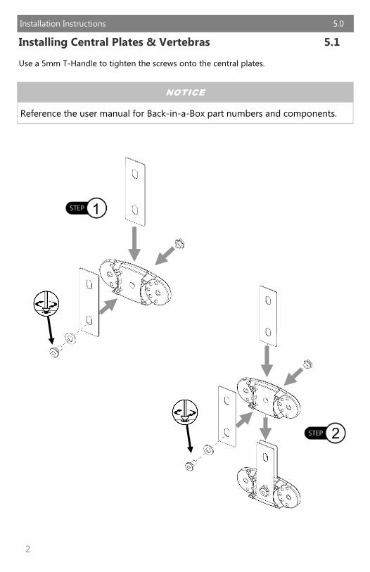
Installing Central Plates & Vertebras 5.1
Use a 5mm T-Handle to tighten the screws onto the central plates.
1
2
NOTICE
Reference the user manual for Back-in-a-Box part numbers and components.

3
Installation Instructions 5.0
3
4

4
Installation Instructions 5.0
Installing Ribs 5.2
Use a 4mm T-Handle to tighten the ribs onto the central plates.
1
2
WARNING
Do not use this device before receiving a clinical evaluation.

5
Installation Instructions 5.0
3
4

6
Installation Instructions 5.0
Uninstalling Vertebras/Ribs 5.3
Using the 4mm T-Handle, loosen the M6 screws to remove the ribs.
1
2
3
7
Installation Instructions 5.0
4
5
8
Installation Instructions 5.0
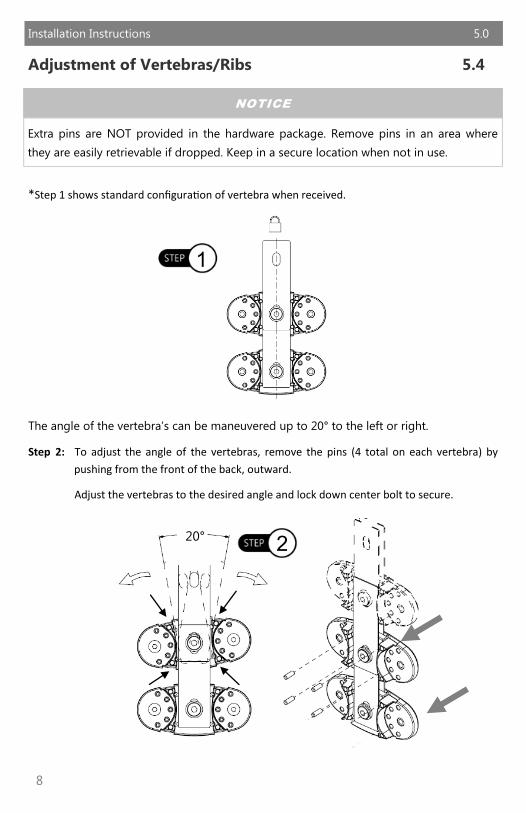
Adjustment of Vertebras/Ribs 5.4
*Step 1 shows standard configuration of vertebra when received.
The angle of the vertebra’s can be maneuvered up to 20° to the left or right.
Step 2: To adjust the angle of the vertebras, remove the pins (4 total on each vertebra) by
pushing from the front of the back, outward.
Adjust the vertebras to the desired angle and lock down center bolt to secure.
1
NOTICE
Extra pins are NOT provided in the hardware package. Remove pins in an area where
they are easily retrievable if dropped. Keep in a secure location when not in use.
20° 2
9
Installation Instructions 5.0
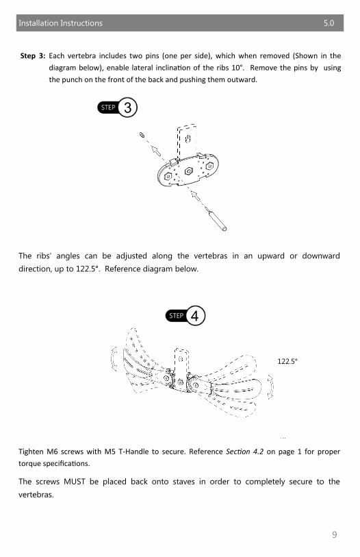
Step 3: Each vertebra includes two pins (one per side), which when removed (Shown in the
diagram below), enable lateral inclination of the ribs 10°. Remove the pins by using
the punch on the front of the back and pushing them outward.
The ribs’ angles can be adjusted along the vertebras in an upward or downward
direction, up to 122.5°. Reference diagram below.
Tighten M6 screws with M5 T-Handle to secure. Reference Section 4.2 on page 1 for proper
torque specifications.
The screws MUST be placed back onto staves in order to completely secure to the
vertebras.
122.5°
4
3

10
Installation Instructions 5.0
Step 5: The total height of the back can be adjusted by tightening/loosening the vertebras with a
5mm T-Handle and compressing or pulling the central plates together or apart.
A minimum distance of 51mm between staves is possible when central plates are
compressed.
A maximum distance of 63mm between staves is possible when the central plates are
separated.
Step 6: To bend the vertebras in a desired angle, untighten the screws on the centerplates and
apply approximately 25Nm of force down on the vertebras.
51mm 63mm
5
6
11
Installation Instructions 5.0
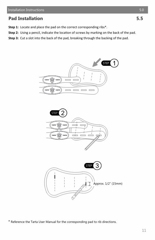
Pad Installation 5.5
Step 1: Locate and place the pad on the correct corresponding ribs*.
Step 2: Using a pencil, indicate the location of screws by marking on the back of the pad.
Step 3: Cut a slot into the back of the pad, breaking through the backing of the pad.
* Reference the Tarta User Manual for the corresponding pad to rib directions.
1
2
Approx. 1/2” (15mm)
3
12
Installation Instructions 5.0
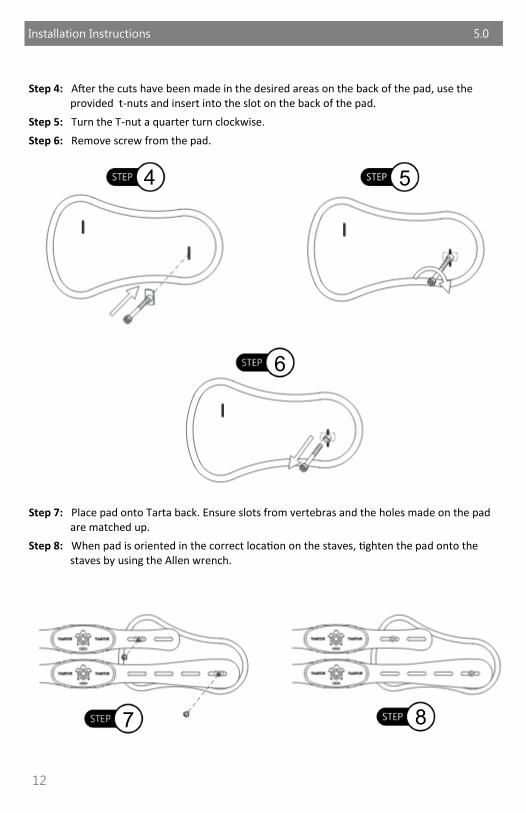
Step 4: After the cuts have been made in the desired areas on the back of the pad, use the provided t-nuts and insert into the slot on the back of the pad.
Step 5: Turn the T-nut a quarter turn clockwise.
Step 6: Remove screw from the pad.
Step 7: Place pad onto Tarta back. Ensure slots from vertebras and the holes made on the pad are matched up.
Step 8: When pad is oriented in the correct location on the staves, tighten the pad onto the staves by using the Allen wrench.
4 5
6
7 8

13
Mounting Hardware Options 6.0
Mounting Hardware 6.1
Tension Strap
The tension strap adds support and helps stabilize the desired section of the Tarta back.
The tension strap should be installed after the back has been installed and final
adjustments have been made.
Step 1: Place provided Velcro strip directly on the middle section of the canes.
Step 2: Wrap the tension strap around the canes. The tighter the strap is pulled the more rigid
the back will be.
Step 3: Attach the strap that has both Hook and Loop Velcro on either side first. The Hook side
of the Velcro should be facing outward to receive the second strap.
Step 4: Wrap the other side of the strap with the Loop side onto the tension strap.
To adjust the tension strap, pull the ends of the strap and separate the Velcro. Pull or loosen the
strap to the desired tension and reattach the straps when complete.
1
Velcro
2
3
Top View
v
v
Strap Pulled Tight
Strap Not Tight
4
Loop Hook
14
Mounting Hardware Options 6.0
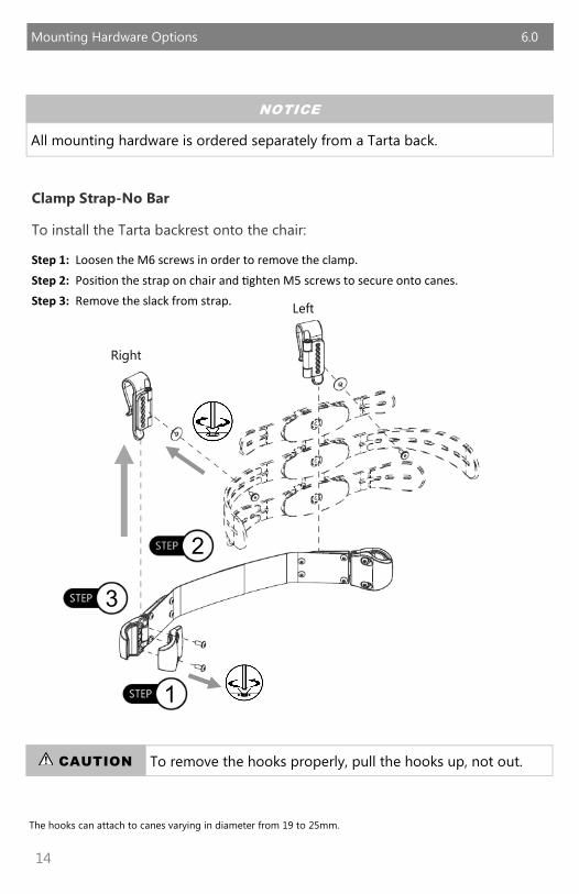
Clamp Strap-No Bar
To install the Tarta backrest onto the chair:
Step 1: Loosen the M6 screws in order to remove the clamp.
Step 2: Position the strap on chair and tighten M5 screws to secure onto canes.
Step 3: Remove the slack from strap.
The hooks can attach to canes varying in diameter from 19 to 25mm.
NOTICE
All mounting hardware is ordered separately from a Tarta back.
CAUTION To remove the hooks properly, pull the hooks up, not out.
C
2
1
3
Right
Left

15
Mounting Hardware Options 6.0
Step 4: Determine the proper location of hooks.
*Ensure the hooks are mounted all the way to the inside or outside of the tracks on the clamps. Mounting in the middle will cause the back to move side to side. See Figures 1, 2 & 3 for correct and incorrect placement on the hooks.
Correct Mountings
Inner Mounting Outer Mounting
Incorrect Mounting
Middle Mount
Figure 1 Figure 2
Figure 3

16
Mounting Hardware Options 6.0
Step 5: Place M6 screws on inside of the back through rib/washer and tighten on the hook.
* Before mounting the clamp, check that the rubber insert on the clamp is properly set and not backwards.
5
Top View
17
Mounting Hardware Options 6.0
NOTICE
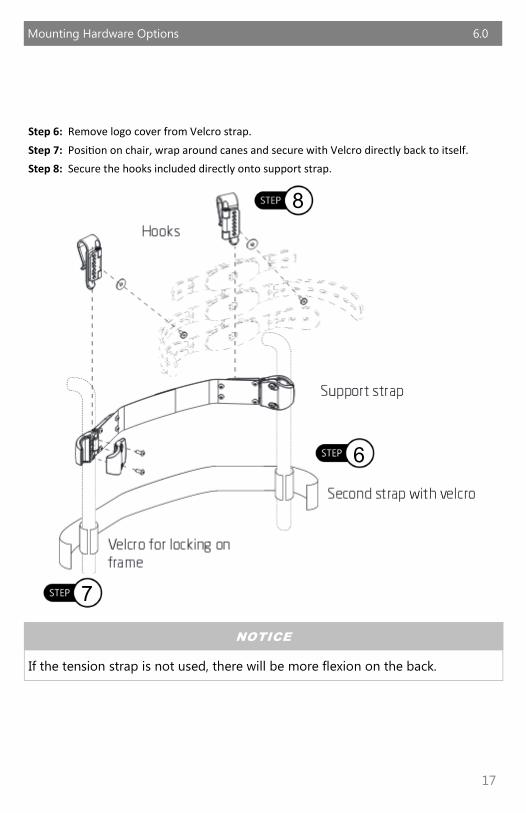
If the tension strap is not used, there will be more flexion on the back.
6
7
8
Step 6: Remove logo cover from Velcro strap.
Step 7: Position on chair, wrap around canes and secure with Velcro directly back to itself.
Step 8: Secure the hooks included directly onto support strap.
18
Mounting Hardware Options 6.0
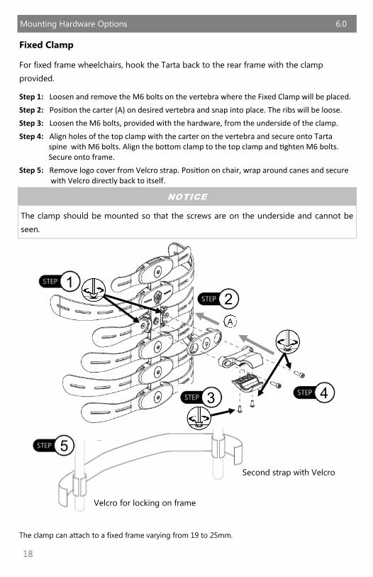
Fixed Clamp
For fixed frame wheelchairs, hook the Tarta back to the rear frame with the clamp
provided.
Step 1: Loosen and remove the M6 bolts on the vertebra where the Fixed Clamp will be placed.
Step 2: Position the carter (A) on desired vertebra and snap into place. The ribs will be loose.
Step 3: Loosen the M6 bolts, provided with the hardware, from the underside of the clamp.
Step 4: Align holes of the top clamp with the carter on the vertebra and secure onto Tarta spine with M6 bolts. Align the bottom clamp to the top clamp and tighten M6 bolts. Secure onto frame.
Step 5: Remove logo cover from Velcro strap. Position on chair, wrap around canes and secure with Velcro directly back to itself.
The clamp can attach to a fixed frame varying from 19 to 25mm.
5
Second strap with Velcro
Velcro for locking on frame
1 2
3 4
A
NOTICE
The clamp should be mounted so that the screws are on the underside and cannot be
seen.
19
Mounting Hardware Options 6.0
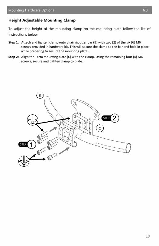
Height Adjustable Mounting Clamp
To adjust the height of the mounting clamp on the mounting plate follow the list of
instructions below:
Step 1: Attach and tighten clamp onto chair rigidizer bar (B) with two (2) of the six (6) M6 screws provided in hardware kit. This will secure the clamp to the bar and hold in place while preparing to secure the mounting plate.
Step 2: Align the Tarta mounting plate (C) with the clamp. Using the remaining four (4) M6 screws, secure and tighten clamp to plate.
B
2
C
1

20
Mounting Hardware Options 6.0
5
Second strap with Velcro
Velcro for locking on frame
Step 3: Determine which vertebra the mounting plate will be attached to. Remove the M6 screws on the vertebra where the clamp will be placed. Position the carter (A) on the vertebra and snap into place. The ribs will be loose. Place the two (2) spacers inside the center mount holes on the carter.
Step 4: Using the M6 screws provided with the mounting hardware, insert the screws into the spacers on the carter, and secure.
Step 5: Remove logo cover from Velcro strap. Position on chair, wrap around canes and secure with Velcro directly back to itself.
3
D
A
4

21
Mounting Hardware Options 6.0
3 Right
* 2 *
Removable Mount
Step 1: Mark tubing at desired height for hardware.
Step 2: Align lever block to height marked on canes. The hardware is side specific. Insets on the
mounting hardware should be facing inward.
Step 3: Slide u-clamp onto cane. Clamp should be outside mounting hardware. Insert two M6
BHS* into hardware and tighten with 3mm T-Handle. Tighten the 4mm bolt under the
locking lever to secure lever block in place.
* Screws included in hardware package.
1
Left
SAFETY
Ensure hardware is installed at the same height on the canes. Installing hardware at
different heights could prevent the back from being properly installed and could cause
injury.

22
Mounting Hardware Options 6.0
Step 4: Locate rigidizer bar. Lower rigidizer bar into hardware mounting insets.
Step 5: Lower the locking lever on the hardware once the bar is in place.
Step 6: When locking lever is in the down position, slide the locking rig over the lever to
prevent breaking or shifting of the hardware.
NOTICE Images shown from behind the chair.
4 5
6

23
Mounting Hardware Options 6.0
Step 7: Using a 5mm T-Handle, secure clamp onto rigidizer bar with the provided M6 x 16mm
SHS (A). The M6 screws will secure the front of the clamp (1) to the back (2).
Step 8: With a 5mm T-Handle, secure the spacer (3) and Tarta plate (4) onto the clamp. Secure
the rigidizer bar using the M6 x 40mm SHS (B).
7
8
1 2 3
4
A
B

24
Mounting Hardware Options 6.0
Step 9: Determine which vertebra the hardware will be mounted to. Remove the carter from
the vertebra and replace with the provided carter containing center mount holes (E).
Position the carter on the vertebra and snap into place. The ribs will be loose. Place
the two spacers inside the center mount holes on the newly installed carter.
Step 10: Align the Tarta back with the Tarta Plate (D). Secure and tighten the M6 x 30mm FHS
(F).
Step 11: Remove logo cover from Velcro strap. Position on chair, wrap around canes and secure with Velcro directly back to itself.
11
9
E
Second strap with Velcro
Velcro for locking on frame
F
10

25
Mounting Hardware Options 6.0
Width Adjustment of Rigidizer Bar 6.2
Step 1: Locate the M6 set screw and M5 nut on the rigidizer bar.
Step 2: With a 3mm T-Handle, slightly loosen the set screw. Do not loosen completely as the M6
nut will fall from the bar.
Step 3: Slide arms of rigidizer bar outward until the desired width is achieved.
Step 4: Ensure the width properly fits on the chair and tighten the M6 set screws.
1 2
3
4

26
Warranty 7.0
The Tarta back is designed and produced to the highest of standards. The
cushions are guaranteed to be free of defects in material and workmanship for a
period of 24 months. If any defect in material or workmanship is found, Pride
Mobility Products will repair or replace, at our discretion, the Tarta pads. This
warranty does not apply to pads abused or misused by the user and deemed
such by Pride Mobility Products.
Claims and repairs shoud be processed through the nearest Pride Mobility provider.
Modification of product without written approval from Pride Mobility Products.
No person is authorized to alter, extend, or waive the warranties of Stealth
Products, LLC. Stealth Products warrants against failure due to defective
materials or workmanship:
Hardware: 5 years
Electronics: 3 years
This warranty does not extend to those items which may require replacement
due to normal wear and tear.
Outer covers
Inner covers
Circumstances beyond the control of Pride
Labor, service calls, shipping, and other charges incurred for repair of the product, unless
specifically authorized, IN ADVANCE, by Pride Mobility Products.
Repairs and/or modifications made to any part without specific consent from Pride
Exclusions also include components with damage caused by:
Exposure to moisture

27
Notes 8.0

28
Notes 8.0

29
Notes 8.0

Stealth Products, LLC. • [email protected] • www.stealthproducts.com
+1(800) 965-9229 | +1(512) 715-9995 | 104 John Kelly Drive, Burnet TX 78611
P129D480R3 Revision Date 2017-11-20