
GoPro Hero4 Negro Edición vs GoPro HD Hero3 + Negro Edición_ ¿Cuál es la diferencia_ - Pocket-lint
Tarot 2-Axis T-2D Brushless Gimbal for GoPro Hero3
User Manual V1.1
Revised by John C. Lin – March 30, 2014
I make no guarantees regarding the proper operation and safety of this device or the
accuracy of this document. This document is for educational purposes only. By
reading further you assume all liability for any direct or indirect injuries that may
result.
I am revising this document out of frustration at the poor instructions that is typical of
many Chinese manufacturers. A product is useless if the customer does not know how
to utilize it to its full potential. I hope this document will save you many hours of
headaches and frustration, and that you can produce some phenomenal videos to
share with the world using this highly effective gimbal.
I do not work for Tarot and am not related in any way to Tarot.
Please read the entire manual before setting up your gimbal. It will save you a lot of
time.
1. Introduction
Tarot T-2D gimbal is designed for the GoPro Hero3 and 3+, which is widely used in film,
television productions, advertising aerial photography, etc. Using 6061T6 aluminum alloy full
CNC precision machining and brushless motors, the T-2D’s framework is designed with
compactness, ease of installation, high precision, lightweight, and high stability in mind. Even
when the aircraft is in high-speed flight, the T-2D can still stabilize and control the GoPro camera
precisely with the highest camera stability, so resulting pictures or videos be of optimal quality.
2. Specifications
1. Supports GoPro Hero3 and Hero3+ video output.
2. Supports reverse power supply protection and power voltage compensation.
3. Supports motor connector short circuit protection.
4. Supports tilt initial angle setting.
5. Supports adjustable gains and 3D virtual attitude display on PC software.
6. Supports Stick Rate and Stick Position modes.
7. Supports receiver types: conventional/S-BUS/DSM2/DSMJ/DSMX.
8. Supports RC: PPM/PCM/2.4G.
9. Operating input voltage: DC 7.4V~14.8V (Lithium Polymer 3S, or 14.8V, is recommended)
10. Operating current: 200-500mA (Depending on power supply voltage and motor power)
11. Operating temperature: -15ºC~65ºC.
12. CPU: Double 32bit ARM
13. Sensor technology: 3-axis MEMS gyro and accelerometer.
14. Max angular rate: 2000 º /sec.
15. Max acceleration: 16g.
16. Control frequency: 2000Hz
17. Motor driver frequency: 20 KHz (quiet and smooth)
18. Control accuracy: 0.1°
19. Control range: -45º ~ 45º (roll), -135º ~ 90 º (tilt).
20. Attitude arithmetic: BLDC (Brushless DC) gimbal motor using decoupled EKF (Extended
Kalman Filter) algorithm.
21. Aerial photography equipment: GoPro Hero3 or Hero3+.
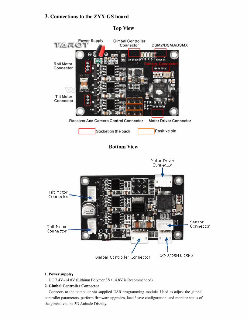
3. Connections to the ZYX-GS board
Top View
Bottom View
1. Power supply::::
DC 7.4V~14.8V (Lithium Polymer 3S / 14.8V is Recommended)
2. Gimbal Controller Connector::::
Connects to the computer via supplied USB programming module. Used to adjust the gimbal
controller parameters, perform firmware upgrades, load / save configuration, and monitor status of
the gimbal via the 3D Attitude Display.
3. Motor driver connector::::
Connects to the computer via supplied USB module. Used to adjust the motor controller
parameters (motor poles, power), perform firmware upgrades, load / save configuration, and
monitor voltage / and current status.
4. Receiver and camera control connector ::::
R: conventional receiver roll channel input
T: conventional receiver tilt channel input
C: conventional receiver stick mode channel input (rate mode and position mode)
S: S-BUS receiver or conventional receiver camera input
P: camera control servo output (Infrared camera module can be connected)
+: 5V output
-: power ground
5. DSM2/DSMJ/DSMX::::
Used to connect DSM2/DSMJ/DSMX receiver
6. Roll and Tilt Motor Connectors::::
Used to connect to the roll and tilt motors on the gimbal. Be sure to connect the appropriate
cables to these connectors. The “roll” connector is the one that goes to the motor that moves the
camera side-to-side as you face the camera. This motor is located towards the BACK of the
gimbal assembly. The “tilt” connector is the one that goes to the motor that causes the camera to
tilt toward you or away from you as you face the camera. This motor is located on the SIDE of the
gimbal assembly.
7. Sensor connector::::
Used to connect to the square Sensor Module that is attached behind the actual GoPro camera
mount on the gimbal.
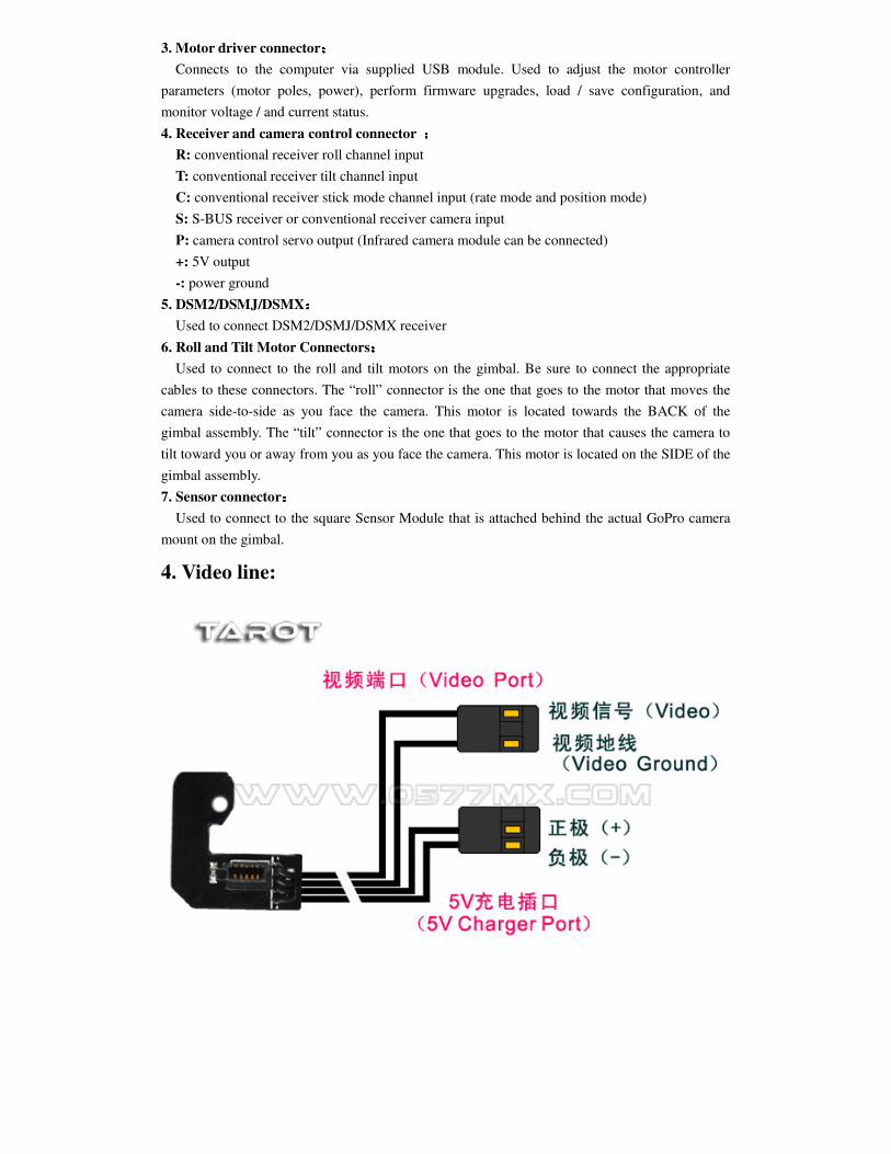
4. Video line:
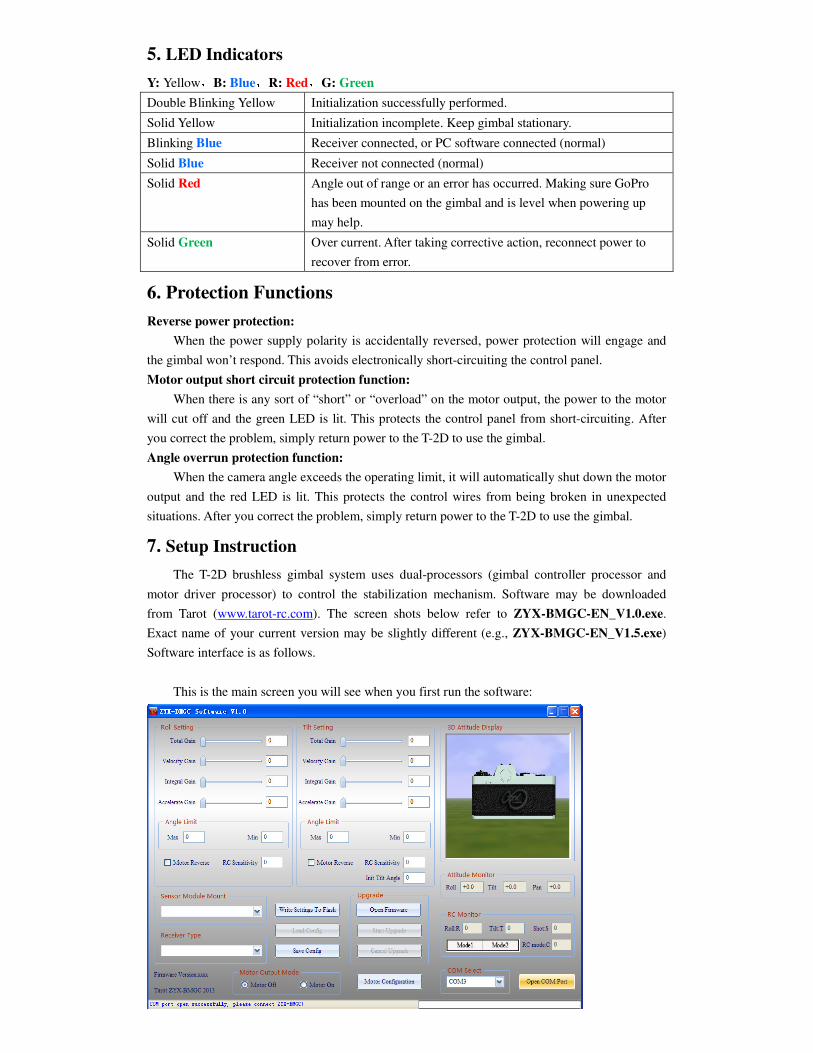
5. LED Indicators
Y: Yellow,B: Blue,R: Red,G: Green
Double Blinking Yellow Initialization successfully performed.
Solid Yellow Initialization incomplete. Keep gimbal stationary.
Blinking Blue Receiver connected, or PC software connected (normal)
Solid Blue Receiver not connected (normal)
Solid Red Angle out of range or an error has occurred. Making sure GoPro
has been mounted on the gimbal and is level when powering up
may help.
Solid Green Over current. After taking corrective action, reconnect power to
recover from error.
6. Protection Functions
Reverse power protection:
When the power supply polarity is accidentally reversed, power protection will engage and
the gimbal won’t respond. This avoids electronically short-circuiting the control panel.
Motor output short circuit protection function:
When there is any sort of “short” or “overload” on the motor output, the power to the motor
will cut off and the green LED is lit. This protects the control panel from short-circuiting. After
you correct the problem, simply return power to the T-2D to use the gimbal.
Angle overrun protection function:
When the camera angle exceeds the operating limit, it will automatically shut down the motor
output and the red LED is lit. This protects the control wires from being broken in unexpected
situations. After you correct the problem, simply return power to the T-2D to use the gimbal.
7. Setup Instruction
The T-2D brushless gimbal system uses dual-processors (gimbal controller processor and
motor driver processor) to control the stabilization mechanism. Software may be downloaded
from Tarot (www.tarot-rc.com). The screen shots below refer to ZYX-BMGC-EN_V1.0.exe.
Exact name of your current version may be slightly different (e.g., ZYX-BMGC-EN_V1.5.exe)
Software interface is as follows.
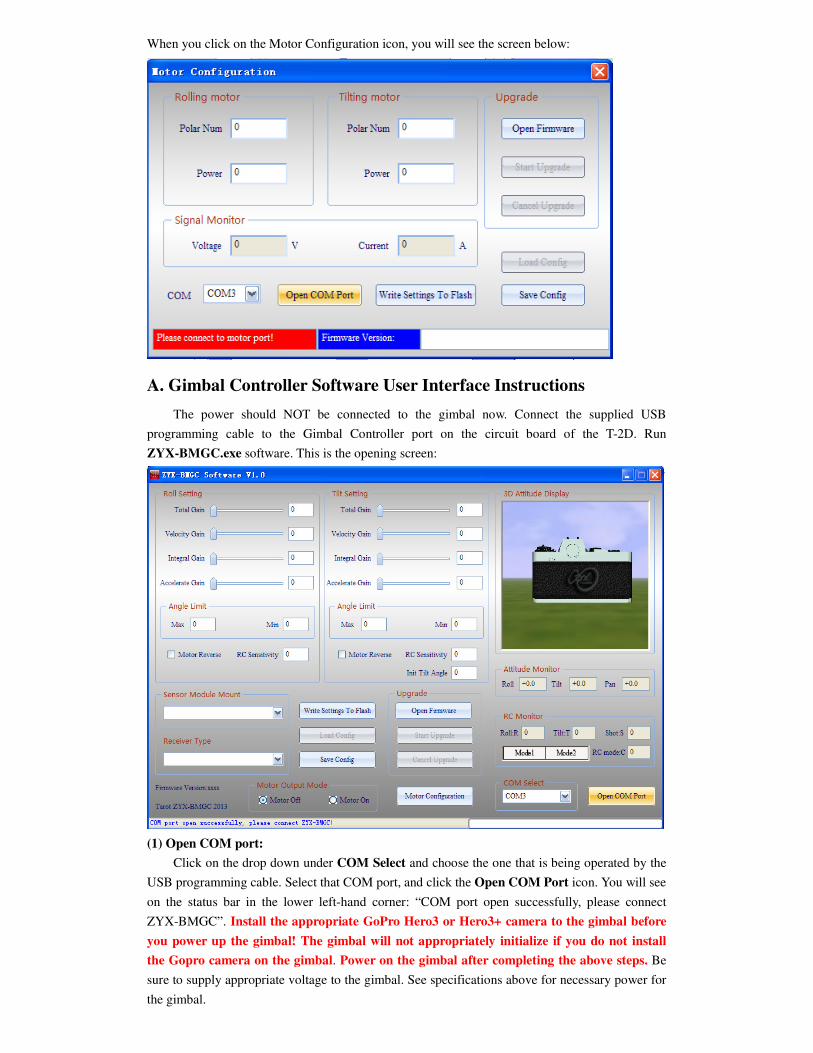
This is the main screen you will see when you first run the software:
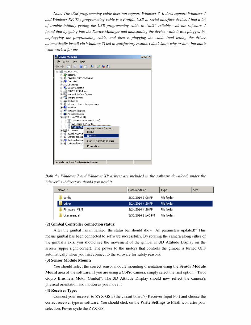
When you click on the Motor Configuration icon, you will see the screen below:
A. Gimbal Controller Software User Interface Instructions
The power should NOT be connected to the gimbal now. Connect the supplied USB
programming cable to the Gimbal Controller port on the circuit board of the T-2D. Run
ZYX-BMGC.exe software. This is the opening screen:
(1) Open COM port:
Click on the drop down under COM Select and choose the one that is being operated by the
USB programming cable. Select that COM port, and click the Open COM Port icon. You will see
on the status bar in the lower left-hand corner: “COM port open successfully, please connect
ZYX-BMGC”. Install the appropriate GoPro Hero3 or Hero3+ camera to the gimbal before
you power up the gimbal! The gimbal will not appropriately initialize if you do not install
the Gopro camera on the gimbal. Power on the gimbal after completing the above steps. Be
sure to supply appropriate voltage to the gimbal. See specifications above for necessary power for
the gimbal.
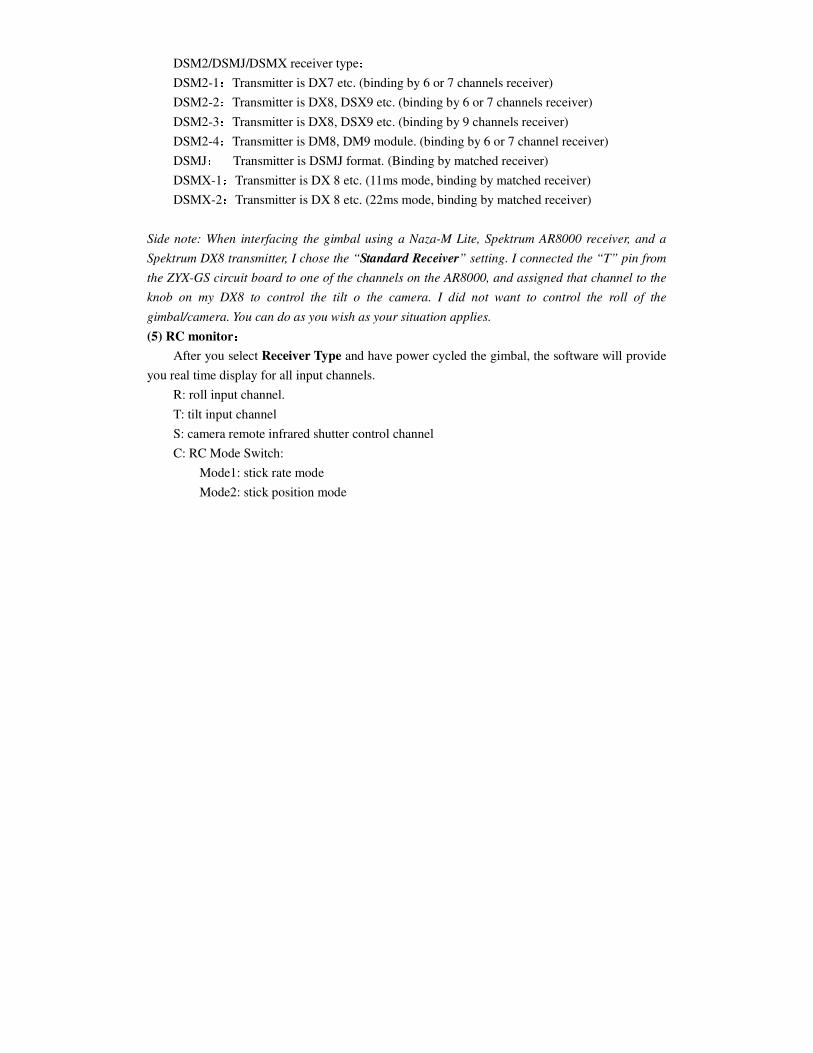
Note: The USB programming cable does not support Windows 8. It does support Windows 7
and Windows XP. The programming cable is a Prolific USB-to-serial interface device. I had a lot
of trouble initially getting the USB programming cable to “talk” reliably with the software. I
found that by going into the Device Manager and uninstalling the device while it was plugged in,
unplugging the programming cable, and then re-plugging the cable (and letting the driver
automatically install via Windows 7) led to satisfactory results. I don’t know why or how, but that’s
what worked for me.
Both the Windows 7 and Windows XP drivers are included in the software download, under the
“driver” subdirectory should you need it.
(2) Gimbal Controller connection status:
After the gimbal has initialized, the status bar should show “All parameters updated!” This
means gimbal has been connected to software successfully. By rotating the camera along either of
the gimbal’s axis, you should see the movement of the gimbal in 3D Attitude Display on the
screen (upper right corner). The power to the motors that controls the gimbal is turned OFF
automatically when you first connect to the software for safety reasons.
(3) Sensor Module Mount::::
You should select the correct sensor module mounting orientation using the Sensor Module
Mount area of the software. If you are using a GoPro camera, simply select the first option, “Tarot
Gopro Brushless Motor Gimbal”. The 3D Attitude Display should now reflect the camera’s
physical orientation and motion as you move it.
(4) Receiver Type:
Connect your receiver to ZYX-GS’s (the circuit board’s) Receiver Input Port and choose the
correct receiver type in software. You should click on the Write Settings to Flash icon after your
selection. Power cycle the ZYX-GS.
DSM2/DSMJ/DSMX receiver type:
DSM2-1:Transmitter is DX7 etc. (binding by 6 or 7 channels receiver)
DSM2-2:Transmitter is DX8, DSX9 etc. (binding by 6 or 7 channels receiver)
DSM2-3:Transmitter is DX8, DSX9 etc. (binding by 9 channels receiver)
DSM2-4:Transmitter is DM8, DM9 module. (binding by 6 or 7 channel receiver)
DSMJ: Transmitter is DSMJ format. (Binding by matched receiver)
DSMX-1:Transmitter is DX 8 etc. (11ms mode, binding by matched receiver)
DSMX-2:Transmitter is DX 8 etc. (22ms mode, binding by matched receiver)
Side note: When interfacing the gimbal using a Naza-M Lite, Spektrum AR8000 receiver, and a
Spektrum DX8 transmitter, I chose the “Standard Receiver” setting. I connected the “T” pin from
the ZYX-GS circuit board to one of the channels on the AR8000, and assigned that channel to the
knob on my DX8 to control the tilt o the camera. I did not want to control the roll of the
gimbal/camera. You can do as you wish as your situation applies.
(5) RC monitor::::
After you select Receiver Type and have power cycled the gimbal, the software will provide
you real time display for all input channels.
R: roll input channel.
T: tilt input channel
S: camera remote infrared shutter control channel
C: RC Mode Switch:
Mode1: stick rate mode
Mode2: stick position mode
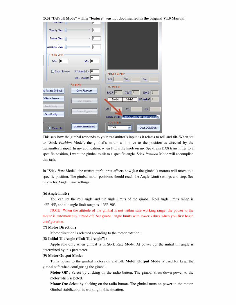
(5.5) “Default Mode” – This “feature” was not documented in the original V1.0 Manual.
This sets how the gimbal responds to your transmitter’s input as it relates to roll and tilt. When set
to “Stick Position Mode”, the gimbal’s motor will move to the position as directed by the
transmitter’s input. In my application, when I turn the knob on my Spektrum DX8 transmitter to a
specific position, I want the gimbal to tilt to a specific angle. Stick Position Mode will accomplish
this task.
In “Stick Rate Mode”, the transmitter’s input affects how fast the gimbal’s motors will move to a
specific position. The gimbal motor positions should reach the Angle Limit settings and stop. See
below for Angle Limit settings.
(6) Angle limits::::
You can set the roll angle and tilt angle limits of the gimbal. Roll angle limits range is
-45º~45º, and tilt angle limit range is -135º~90º.
NOTE: When the attitude of the gimbal is not within safe working range, the power to the
motor is automatically turned off. Set gimbal angle limits with lower values when you first begin
configuration.
(7) Motor Direction::::
Motor direction is selected according to the motor rotation.
(8) Initial Tilt Angle (“Init Tilt Angle”)::::
Applicable only when gimbal is in Stick Rate Mode. At power up, the initial tilt angle is
determined by this parameter.
(9) Motor Output Mode:
Turns power to the gimbal motors on and off. Motor Output Mode is used for keep the
gimbal safe when configuring the gimbal.
Motor Off : Select by clicking on the radio button. The gimbal shuts down power to the
motor when selected.
Motor On: Select by clicking on the radio button. The gimbal turns on power to the motor.
Gimbal stabilization is working in this situation.
NOTE:
(a) Adjust Sensor Module mounting and orientation only with the Motor Off.
(b) There are two situations that the gimbal will automatically shut down power to the motors
while Motor On is selected:
1. When the Total Gain is set to zero or other three gain settings are zero on any axis.
2. When the attitude of the gimbal is outside of angle limit ranges.
Be sure to set gain values to non-zero, keep the gimbal level, and make sure the Sensor
Module orientation is correct before turning on the motors.
(10) PID parameters adjustment:
This refers to the Roll Setting and Tilt Setting sections of the software.
PID parameters range is [0-500]. The basic rule is that Total Gain cannot be 0, and Velocity
Gain and Integration Gain cannot both be 0. Motors will turn off if above rules are not followed.
If you increase the Power settings to the Rolling and Tilting motors (under Motor
Configuration menu/screen), you should correspondingly reduce the gimbal gains. If you decrease
the Power settings, you should likewise increase the gains settings. In order to achieve optimal
gimbal stabilization performance, you should minimize Power values to the motors and increase
gains. Please note that reducing motor power will affect the gimbal’s ability to counteract
resistance to the gimbal’s movement (eg., strong winds).
Step 1. Accelerate Gain:
First, set Total Gain to an appropriate value (e.g. 100). Set the Velocity Gain and
Integral Gain to the minimum value (e.g. 1). Secondly, increase Acceleration Gain
gradually until the gimbal starts to shake. This value is the maximum Acceleration
Gain. Reduce the Acceleration Gain by 20% as the final gain setting.
You can use the slider bars or enter numerical values in the appropriate fields to adjust
gain settings. You should press the Enter key and wait a few seconds before making
adjustments in other gain settings.
Step 2. Velocity Gain:
Increase Velocity Gain gradually until the gimbal starts to shake. This is the maximum
Velocity Gain value. Reduce the Velocity Gain by 20% as the final gain setting.
Step 3. Integral Gain:
Increase Integral Gain gradually until the gimbal starts to shake. This is the maximal
Integral Gain value. Reduce the Integral Gain by 20% as the final gain.
Step 4. Fine-Tune Gain Settings:
You can always adjust and fine-tune the above gain settings as appropriate to achieve
optimal results to your liking.
Side note: Your software should include default configuration settings for the GoPro camera
and you don’t need to mess with the gain settings. I simply loaded the default settings and my
gimbal stabilization worked perfectly.
To load the default config settings:
In the software, click the Load Config icon. Navigate to the config folder of your gimbal
software and choose gopro.bgsc. There should be only one config file from which to choose.
You should notice that the gimbal is rock steady at the time and stabilization working
perfectly.
(11) Write Settings to Flash::::
After your configuration is complete, click on the Write Settings To Flash icon. When Flash
memory has been successfully written, the settings you created are finally saved in the gimbal.
These settings are loaded automatically the next time you start the gimbal.
Note: None of the settings are saved to the gimbal if you do not Write Settings to Flash. This is
imperative to perform after you have configured your software settings.
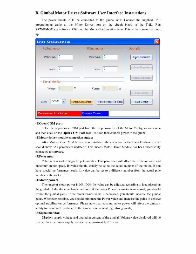
B. Gimbal Motor Driver Software User Interface Instructions
The power should NOT be connected to the gimbal now. Connect the supplied USB
programming cable to the Motor Driver port on the circuit board of the T-2D. Run
ZYX-BMGC.exe software. Click on the Motor Configuration icon. This is the screen that pops
up:
(1)Open COM port:
Select the appropriate COM port from the drop down list of the Motor Configuration screen
and then click on the Open COM Port icon. You can then connect power to the gimbal.
(2)Motor driver module connection status:
After Motor Driver Module has been initialized, the status bar in the lower left-hand corner
should show “All parameters updated!” This means Motor Driver Module has been successfully
connected to software.
(3)Polar num:
Polar num is motor magnetic pole number. This parameter will affect the reduction ratio and
maximum motor speed. Its value should usually be set to the actual number of the motor. If you
have special performance needs, its value can be set to a different number from the actual pole
number of the motor.
(4)Motor power:
The range of motor power is 0%-100%. Its value can be adjusted according to load placed on
the gimbal. Under the same load conditions, if the motor Power parameter is increased, you should
reduce the gimbal gains. If the motor Power value is decreased, you should increase the gimbal
gains. Whenever possible, you should minimize the Power value and increase the gains to achieve
optimal stabilization performance. Please note that reducing motor power will affect the gimbal’s
ability to counteract resistance to the gimbal’s movement (eg., strong winds).
(5)Signal monitor:
Displays supply voltage and operating current of the gimbal. Voltage value displayed will be
smaller than the power supply voltage by approximately 0.3 volts.
(6)Write settings to flash:
After your motor configuration is complete, click on the Write Settings To Flash icon.
When Flash memory has been successfully written, the settings you created are finally saved in
the gimbal. These settings are loaded automatically the next time you start the gimbal.
Note: None of the settings are saved to the gimbal if you do not Write Settings to Flash. This is
imperative to perform after you have configured your software settings.
8. Firmware Upgrade
The T-2D gimbal controller uses 2 CPUs (Central Processing Units): one for the main
controller CPU and another for the motor. Consequently, firmware upgrade is a two-step process,
requiring two separate files for these individual CPUs. Before upgrading the firmware, you should
make sure the hardware interface is correctly connected and to choose the correct / latest firmware
files. Please follow these directions EXACTLY or else your firmware upgrade will fail!
1. Main controller firmware upgrade process:
Make sure the power is NOT connected to the gimbal at this time!!!
1. Connect USB programming cable to the Main Controller port
2. Choose the correct COM port associated with the USB programming cable in the
software. Do not click on the Open COM Port icon.
3. Click on the Open Firmware icon
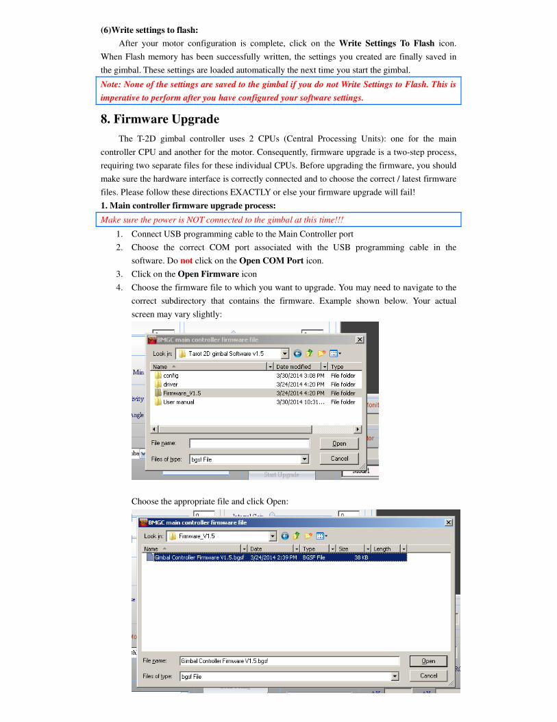
4. Choose the firmware file to which you want to upgrade. You may need to navigate to the
correct subdirectory that contains the firmware. Example shown below. Your actual
screen may vary slightly:
Choose the appropriate file and click Open:
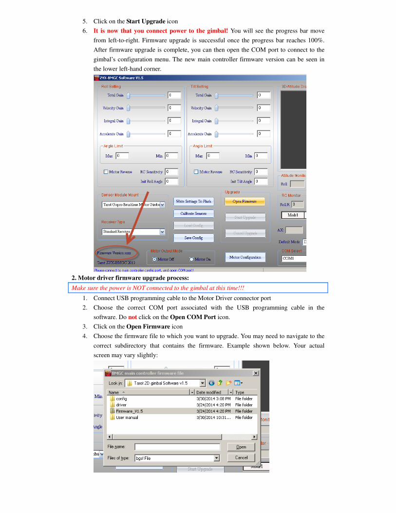
5. Click on the Start Upgrade icon
6. It is now that you connect power to the gimbal! You will see the progress bar move
from left-to-right. Firmware upgrade is successful once the progress bar reaches 100%.
After firmware upgrade is complete, you can then open the COM port to connect to the
gimbal’s configuration menu. The new main controller firmware version can be seen in
the lower left-hand corner.
2. Motor driver firmware upgrade process:
Make sure the power is NOT connected to the gimbal at this time!!!
1. Connect USB programming cable to the Motor Driver connector port
2. Choose the correct COM port associated with the USB programming cable in the
software. Do not click on the Open COM Port icon.
3. Click on the Open Firmware icon
4. Choose the firmware file to which you want to upgrade. You may need to navigate to the
correct subdirectory that contains the firmware. Example shown below. Your actual
screen may vary slightly:
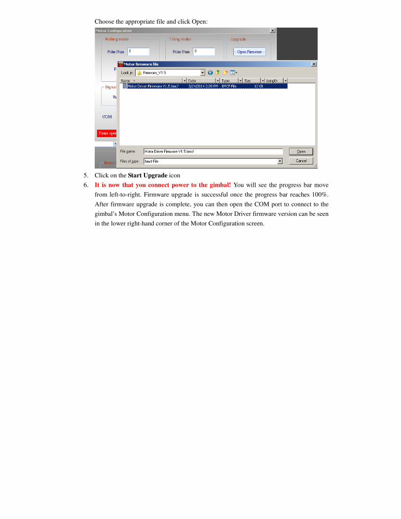
Choose the appropriate file and click Open:
5. Click on the Start Upgrade icon
6. It is now that you connect power to the gimbal! You will see the progress bar move
from left-to-right. Firmware upgrade is successful once the progress bar reaches 100%.
After firmware upgrade is complete, you can then open the COM port to connect to the
gimbal’s Motor Configuration menu. The new Motor Driver firmware version can be seen
in the lower right-hand corner of the Motor Configuration screen.