TARGA Manual rev1511 - jamesenterprises.netjamesenterprises.net/Unifire_Files/TARGA PLC Manual...
11
TARGA Robotic Nozzle PLC operating manual Rev 2015 11 1 of 11 TARGA operating manual F3 F4 F5 F1 F2 robotic nozzle control system USB calibration navigation TARGA PLC
Transcript of TARGA Manual rev1511 - jamesenterprises.netjamesenterprises.net/Unifire_Files/TARGA PLC Manual...
TARGA Robotic Nozzle PLCoperating manual
Rev 2015 11 !1 of !11 TARGA operating manual
F3 F4 F5
F1
F2
robotic nozzle control system
USB
calibration navigation
TARGA PLC
TARGA Robotic Nozzle PLC operating manual
Table of Content:
PAGE 1 - main page 3 Start/overview 3
Navigation 3
PAGE 2 - MK motor control 4 MK (motor control) 4
Manual control from the TARGA PANEL 4
Calibration explained: 5
PAGE 2 - calibration of operating range 6 Calibration MANUAL (F1/F2) 6
Calibration FIXPOINT (F5) 7
PAGE 3 - IOin 8 Digital and analog inputs status page 8
PAGE 4 - IOout 8 Digital output status page 8
PAGE 5 - analogue inputs: 9 Calibration of analog inputs page 9
PAGE 6 - EEprom test 10
PAGE 7 - SPIext test 10
TARGA PLC programming explained 11
Rev 2015 11 !2 of !11 TARGA operating manual
For video instructions on the specific topics, please visit
WWW.UNIFIREACADEMY.COM
PAGE 1 - main page
Start/overviewOn the main page there is general information about the system.
From top to bottom and left to right:
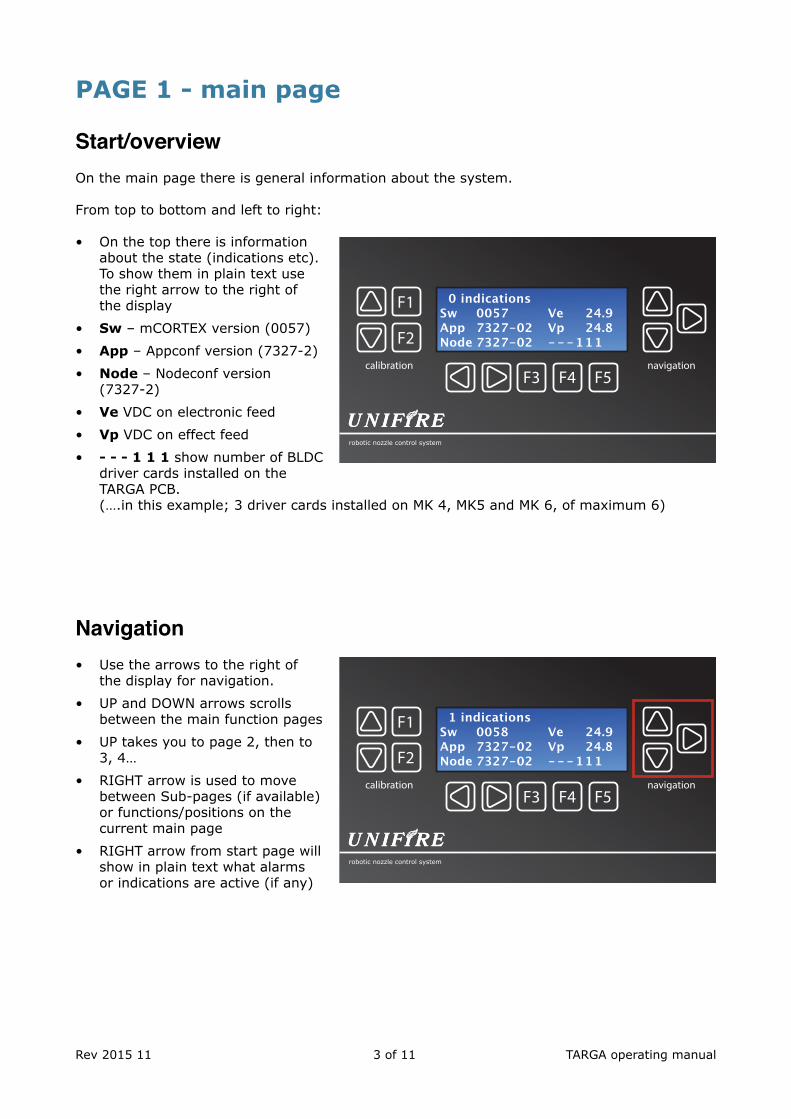
• On the top there is informationabout the state (indications etc).To show them in plain text usethe right arrow to the right ofthe display
• Sw – mCORTEX version (0057)
• App – Appconf version (7327-2)
• Node – Nodeconf version(7327-2)
• Ve VDC on electronic feed
• Vp VDC on effect feed
• - - - 1 1 1 show number of BLDCdriver cards installed on theTARGA PCB.(….in this example; 3 driver cards installed on MK 4, MK5 and MK 6, of maximum 6)
Navigation• Use the arrows to the right of
the display for navigation.
• UP and DOWN arrows scrollsbetween the main function pages
• UP takes you to page 2, then to3, 4…
• RIGHT arrow is used to movebetween Sub-pages (if available)or functions/positions on thecurrent main page
• RIGHT arrow from start page willshow in plain text what alarmsor indications are active (if any)
Rev 2015 11 !3 of !11 TARGA operating manual
F3 F4 F5
F1
F2
robotic nozzle control system
calibration navigation
F3 F4 F5
F1
F2
robotic nozzle control system
calibration navigation
1 indicationsSw 0058 Ve 24.9 App 7327-02 Vp 24.8 Node 7327-02 - - - 1 1 1
0 indicationsSw 0057 Ve 24.9 App 7327-02 Vp 24.8 Node 7327-02 - - - 1 1 1
PAGE 2 - MK motor control
MK (motor control)
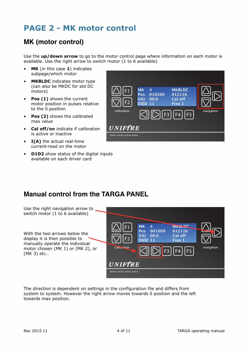
Use the up/down arrow to go to the motor control page where information on each motor is available. Use the right arrow to switch motor (1 to 6 available)
• MK (in this case 1) indicatessubpage/which motor
• MKBLDC indicates motor type(can also be MKDC for std DCmotors)
• Pos (1) shows the currentmotor position in pulses relativeto the 0 position
• Pos (2) shows the calibratedmax value
• Cal off/on indicate if calibrationis active or inactive
• I(A) the actual real-timecurrent-read on the motor
• D1D2 show status of the digital inputsavailable on each driver card
Manual control from the TARGA PANEL
Use the right navigation arrow to switch motor (1 to 6 available)
With the two arrows below the display it is then possible to manually operate the individual motor chosen (MK 1) or (MK 2), or (MK 3) etc..
The direction is dependent on settings in the configuration file and differs from system to system. However the right arrow moves towards 0 position and the left towards max position.
Rev 2015 11 !4 of !11 TARGA operating manual
F3 F4 F5
F1
F2
robotic nozzle control system
calibration navigation
F3 F4 F5
F1
F2
robotic nozzle control system
calibration navigation
MK 4 MKBLDC Pos 001009 012116 I(A) 00.0 Cal off D1D2 11 Fixp 1
MK 4 MKBLDC Pos 010200 012116 I(A) 00.0 Cal off D1D2 11 Fixp 1
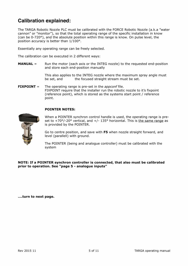
Calibration explained:The TARGA Robotic Nozzle PLC must be calibrated with the FORCE Robotic Nozzle (a.k.a ”water cannon” or ”monitor”), so that the total operating range of the specific installation in know (can be 0-720°), and the absolute position within this range is know. On pulse level, the position accuracy is better than 1/100°.
Essentially any operating range can be freely selected.
The calibration can be executed in 2 different ways:
MANUAL = Run the motor (each axis or the INTEG nozzle) to the requested end-position and store each end-position manually
This also applies to the INTEG nozzle where the maximum spray angle must be set, and the focused straight stream must be set.
FIXPOINT = The operating range is pre-set in the appconf file. FIXPOINT require that the installer run the robotic nozzle to it’s fixpoint(reference point), which is stored as the systems start point / reference point.
POINTER NOTES:
When a POINTER synchron control handle is used, the operating range is pre- set to +70°/-20° vertical, and +/- 135° horizontal. This is the same range as is provided by the POINTER.
Go to centre position, and save with F5 when nozzle straight forward, and level (parallell) with ground.
The POINTER (being and analogue controller) must be calibrated with the system
NOTE: If a POINTER synchron controller is connected, that also must be calibrated prior to operation. See ”page 5 - analogue inputs”
….turn to next page.
Rev 2015 11 !5 of !11 TARGA operating manual
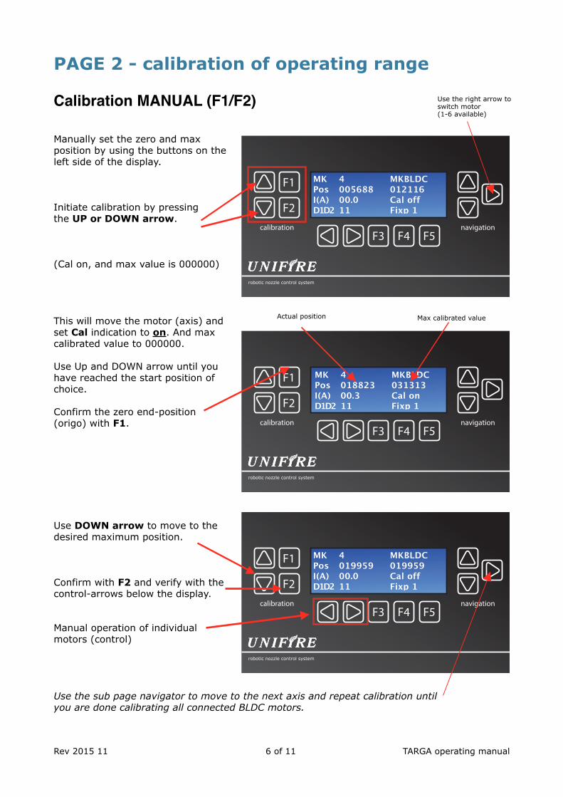
PAGE 2 - calibration of operating range
Calibration MANUAL (F1/F2)
Manually set the zero and max position by using the buttons on the left side of the display.
Initiate calibration by pressing the UP or DOWN arrow.
(Cal on, and max value is 000000)
This will move the motor (axis) and set Cal indication to on. And max calibrated value to 000000.
Use Up and DOWN arrow until you have reached the start position of choice.
Confirm the zero end-position (origo) with F1.
Use DOWN arrow to move to the desired maximum position.
Confirm with F2 and verify with the control-arrows below the display.
Manual operation of individual motors (control)
Use the sub page navigator to move to the next axis and repeat calibration until you are done calibrating all connected BLDC motors.
Rev 2015 11 !6 of !11 TARGA operating manual
F3 F4 F5
F1
F2
robotic nozzle control system
calibration navigation
F3 F4 F5
F1
F2
robotic nozzle control system
calibration navigation
MK 4 MKBLDC Pos 019959 019959 I(A) 00.0 Cal off D1D2 11 Fixp 1
MK 4 MKBLDC Pos 005688 012116 I(A) 00.0 Cal off D1D2 11 Fixp 1
Use the right arrow to switch motor (1-6 available)
F3 F4 F5
F1
F2
robotic nozzle control system
calibration navigation
MK 4 MKBLDC Pos 018823 031313 I(A) 00.3 Cal on D1D2 11 Fixp 1
Actual position Max calibrated value
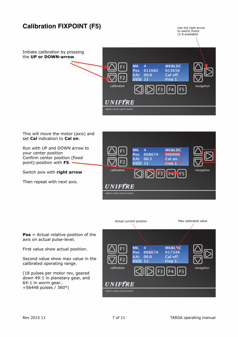
Calibration FIXPOINT (F5)
Initiate calibration by pressing the UP or DOWN-arrow
This will move the motor (axis) and set Cal indication to Cal on.
Run with UP and DOWN arrow to your center position Confirm center position (fixed point)-position with F5.
Switch axis with right arrow
Then repeat with next axis.
Pos = Actual relative position of the axis on actual pulse-level.
First value show actual position.
Second value show max value in the calibrated operating range.
(18 pulses per motor rev, geared down 49:1 in planetary gear, and 64:1 in worm gear… =56448 pulses / 360°)
Rev 2015 11 !7 of !11 TARGA operating manual
F3 F4 F5
F1
F2
robotic nozzle control system
calibration navigation
MK 4 MKBLDC Pos 008674 017348 I(A) 00.0 Cal off D1D2 11 Fixp 1
F3 F4 F5
F1
F2
robotic nozzle control system
calibration navigation
MK 4 MKBLDC Pos 011682 013656 I(A) 00.0 Cal off D1D2 11 Fixp 1
Use the right arrow to switch motor (1-6 available)
Actual current position Max calibrated value
F3 F4 F5
F1
F2
robotic nozzle control system
calibration navigation
MK 4 MKBLDC Pos 008674 000000 I(A) 00.3 Cal on D1D2 11 Fixp 1
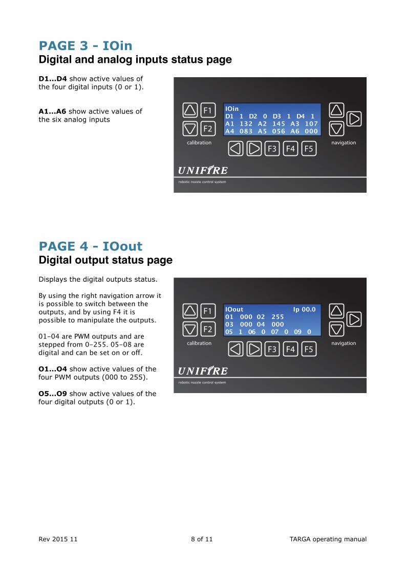
PAGE 3 - IOin Digital and analog inputs status pageD1...D4 show active values of the four digital inputs (0 or 1).
A1...A6 show active values of the six analog inputs
PAGE 4 - IOout Digital output status pageDisplays the digital outputs status.
By using the right navigation arrow it is possible to switch between the outputs, and by using F4 it is possible to manipulate the outputs.
01-04 are PWM outputs and are stepped from 0-255. 05-08 are digital and can be set on or off.
O1...O4 show active values of the four PWM outputs (000 to 255).
O5...O9 show active values of the four digital outputs (0 or 1).
Rev 2015 11 !8 of !11 TARGA operating manual
F3 F4 F5
F1
F2
robotic nozzle control system
calibration navigation
IOout Ip 00.001 000 02 25503 000 04 00005 1 06 0 07 0 09 0
F3 F4 F5
F1
F2
robotic nozzle control system
calibration navigation
IOinD1 1 D2 0 D3 1 D4 1A1 132 A2 145 A3 107A4 083 A5 056 A6 000
PAGE 5 - analogue inputs: Calibration of analog inputs page
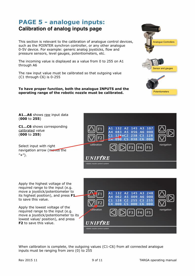
This section is relevant to the calibration of analogue control devices, such as the POINTER synchron controller, or any other analogue 0-5V device. For example: generic analog joysticks, flow and pressure sensors, level gauges, potentiometers, etc.
The incoming value is displayed as a value from 0 to 255 on A1 through A6
The raw input value must be calibrated so that outgoing value(C1 through C6) is 0-255
To have proper function, both the analogue INPUTS and the operating range of the robotic nozzle must be calibrated.
A1...A6 shows raw input data (000 to 255)
C1...C6 shows corresponding calibrated value (000 to 255)
Select input with right navigation arrow (moves the ”*”).
Apply the highest voltage of the required range to the input (e.g. move a joystick/potentiometer to its highest position), and press F1 to save this value.
Apply the lowest voltage of the required range to the input (e.g. move a joystick/potentiometer to its lowest value/ position), and press F2 to save this value.
When calibration is complete, the outgoing values (C1-C6) from all connected analogue inputs must be ranging from zero (0) to 255
Rev 2015 11 !9 of !11 TARGA operating manual
F3 F4 F5
F1
F2
robotic nozzle control system
calibration navigation
A1 132 A2 145 A3 107A4 083 A5 056 A6 000C1 128 C2 238 C3 128C4 090 C5 038 C6 000*
F3 F4 F5
F1
F2
robotic nozzle control system
calibration navigation
A1 132 A2 145 A3 248A4 062 A5 009 A6 000C1 128 C2 255 C3 255C4 000 C5 000 C6 000
Analogue Controllers
Sensor and gauges
Potentiometers
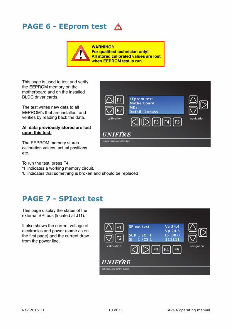
PAGE 6 - EEprom test
This page is used to test and verify the EEPROM memory on the motherboard and on the installed BLDC driver cards.
The test writes new data to all EEPROM’s that are installed, and verifies by reading back the data.
All data previously stored are lost upon this test.
The EEPROM memory stores calibration values, actual positions, etc.
To run the test, press F4. ‘1’ indicates a working memory circuit. ‘0’ indicates that something is broken and should be replaced
PAGE 7 - SPIext test This page display the status of the external SPI bus (located at J11).
It also shows the current voltage of electronics and power (same as on the first page) and the current draw from the power line.
Rev 2015 11 !10 of !11 TARGA operating manual
F3 F4 F5
F1
F2
robotic nozzle control system
calibration navigation
SPIext test Ve 24.4 Vp 24.3
SCK 1 SO 1 Ip 00.0 SI 1 /CS 1 111111
F3 F4 F5
F1
F2
robotic nozzle control system
calibration navigation
EEprom testMotherboard:MKs:0=fail 1=pass
WARNING!!For qualified technician only!All stored calibrated values are lost when EEPROM test is run.
TARGA PLC programming explained What are the Sw, App and Node files?
mCORTEX (Sw) = Operating System
This is the framework under which the nodeconf and appconf can run.
The mCORTEX is generic and essentially stays the same regardless of what the system
looks like. The mCORTEX is updated, however, as soon as new generic functions are added.
appconf (App) = Automation configuration
This file defines what the connected components are and what they do.
For example, if the motors are installed on the robotic nozzle, how many and what type of robotic nozzle etc. (The motors can also be used for running actuators of various kinds)
Furthermore, the appconf can address an input to run a specific sequence (such as to open a valve, or to run a pre-recorded spray sequence.
nodeconf (Node) = System configuration
Defines and tells the TARGA what components are physically connected to the TARGA for each specific system.
For example: how many motors, how many and what type of Joystick or controller, what analogue and digital inputs and outputs are connected, etc.
Also, the nodeconf defines if the TARGA is a Canbus Master in a larger system with additional TARGA’s or external Canbus I/O units.
Rev 2015 11 !11 of !11 TARGA operating manual


![PLC Manual[1]](https://static.fdocuments.in/doc/165x107/577ce72c1a28abf10394815b/plc-manual1.jpg)