Tapping Guide PVC Pipe Tapping Guide.pdf · tapping blanket, can create a more hazardous failure...
23
Tapping Guide For PVC Pressure Pipe UNI-BELL PVC PIPE ASSOCIATION
Transcript of Tapping Guide PVC Pipe Tapping Guide.pdf · tapping blanket, can create a more hazardous failure...
Tapping
Guide
For
PVC
Pressure
Pipe
UNI-BELL PVC PIPE ASSOCIATION
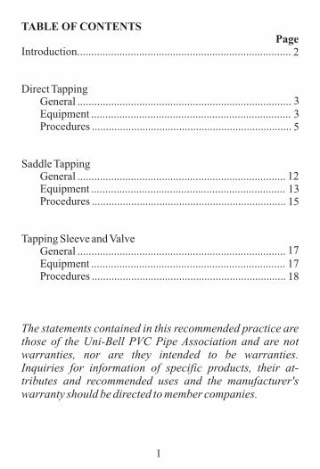
TABLE OF CONTENTSPage
Introduction............................................................................
Direct Tapping General ............................................................................ Equipment ....................................................................... Procedures .......................................................................
Saddle Tapping General .......................................................................... Equipment ..................................................................... Procedures .....................................................................
Tapping Sleeve and Valve General .......................................................................... Equipment ..................................................................... Procedures .....................................................................
The statements contained in this recommended practice are those of the Uni-Bell PVC Pipe Association and are not warranties, nor are they intended to be warranties. Inquiries for information of specific products, their at-tributes and recommended uses and the manufacturer's warranty should be directed to member companies.
1
2
335
121315
18
1717

INTRODUCTION
This booklet has been developed by the Uni-Bell PVC Pipe Association for use as a field tapping guide. Detailed informa-tion regarding recommended procedures and equipment for tap-ping PVC and PVCO pressure pipe is included.
The Uni-Bell PVC Pipe Association, formed in 1971, conducts research and development, provides technical service and sup-port, develops recommended standards and promotes proper use of PVC pipe with gasketed joints.
Its members are manufacturers who are dedicated to producing high quality PVC pipe products for the industry.
This guide provides recommendations for tools, procedures, and acceptable pipe products for three types of taps: direct taps, saddle taps, and taps through a sleeve and valve.
Note: This Tapping Guide is not intended to take the place of the designer's judgment. The illustrations used in this Guide depict specific tooling for the sake of clarity. They are not intended to promote specific types of equipment or the equipment of a particular manufacturer. Other equipment meeting the requirements called for may be equally satisfactory.
2
3
DIRECT TAPPING GENERALGENERALDIRECT TAPPING GENERALDirect tapping involves the tapping of threads into the pipe wall and the insertion of a corporation stop. Direct tapping is recom-mended for PVC water distribution pipe manufactured in ac-cordance with AWWA C900 in nominal sizes 6 inch through 12 inch (150 mm through 300 mm) in DR 18 and DR 14.
DIRECT TAPPING IS NOT RECOMMENDED FOR DR 25 PIPE, NOR IS IT RECOMMENDED FOR 4 INCH DR 18 AND DR 14 PIPE. DIRECT TAPPING IS NOT PERMITTED ON ANY SIZE OF MOLECULARLY ORIENTED (PVCO) PIPE. IN THESE CASES, SERVICE CLAMPS OR SADDLES SHOULD BE USED.
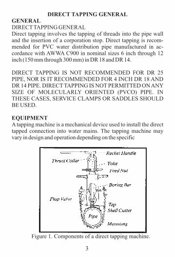
EQUIPMENTA tapping machine is a mechanical device used to install the direct tapped connection into water mains. The tapping machine may vary in design and operation depending on the specific
Figure 1. Components of a direct tapping machine.
4
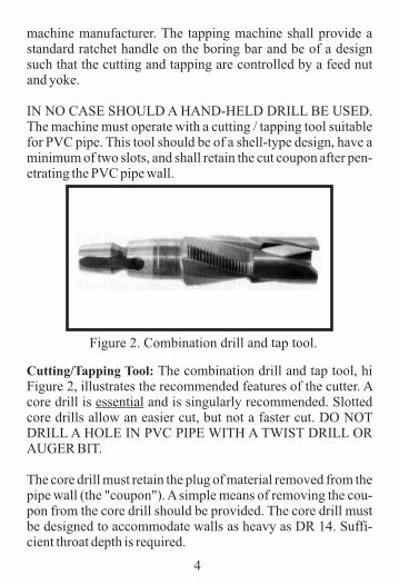
machine manufacturer. The tapping machine shall provide a standard ratchet handle on the boring bar and be of a design such that the cutting and tapping are controlled by a feed nut and yoke.
IN NO CASE SHOULD A HAND-HELD DRILL BE USED. The machine must operate with a cutting / tapping tool suitable for PVC pipe. This tool should be of a shell-type design, have a minimum of two slots, and shall retain the cut coupon after pen-etrating the PVC pipe wall.
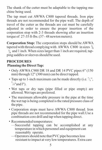
Cutting/Tapping Tool: The combination drill and tap tool, hi Figure 2, illustrates the recommended features of the cutter. A core drill is essential and is singularly recommended. Slotted core drills allow an easier cut, but not a faster cut. DO NOT DRILL A HOLE IN PVC PIPE WITH A TWIST DRILL OR AUGER BIT.
The core drill must retain the plug of material removed from the pipe wall (the "coupon"). A simple means of removing the cou-pon from the core drill should be provided. The core drill must be designed to accommodate walls as heavy as DR 14. Suffi-cient throat depth is required.
Figure 2. Combination drill and tap tool.
5
The shank of the cutter must be adaptable to the tapping ma-chine being used.
Only AWWA C900 DR 18 and DR 14 PVC pipes 6" (150 mm) through 12" (300 mm) can be direct tapped.
5Taps up to 1-inch maximum can be made directly (i.e. / ”, 83/4"and l").
Wet taps or dry taps (pipe filled or pipe empty) are allowed. Wet taps are preferred.
The maximum allowable pressure in the pipe at the time the wet tap is being completed is the rated pressure class of the pipe.
Corporation stops must have AWWA C800 thread. Iron pipe threads are not recommended for the pipe wall.Use a combination core drill and tap when tapping direct.
Recommended temperatures:—Successful tapping can be accomplished at any
temperature in which personnel and equipment can reasonably operate.—Operators should note that PVC pipe becomes less resistant to impact at very low temperatures. Extra care
oo
•
•
•
•
•
•
The tap must cut AWWA C800 tapered threads. Iron pipe threads are not recommended for the pipe wall. The depth of travel of the cutter as the threads are cut must be carefully adjusted in order to ensure the proper insertion of the corporation stop with 2-3 threads showing after an insertion torque of 27-35 ft-lbs. (37 - 48 newton meters).
Corporation Stop: The corporation stops should be AWWA tapered with thread complying with AWWA C800 in sizes and 1 inch. When sizes larger than 1 inch are required, tap-ping saddles or sleeves should be used.
PROCEDURES Planning the Direct Tap:
lll3/4
5/8
should be exercised in handling equipment and in cutting. At very high temperatures, PVC pipe becomes more flexible, and thus more susceptible to over-tightening of tapping machines or saddles.
Placement—Tap not closer than 24 in. (600 mm) from both the back of
the bell and the spigot insertion line.—Stagger multiple taps and keep them at least 18" (450 mm)
apart lengthwise. Thus, the minimum spacing along the same line is 36" (900 mm).
—Do not tap a curved pipe if the radius of the bend is lessthan 300 times the pipe outside diameter.
Do a test tap in the shop before starting field tapping.—Do a couple of dry bench taps to establish the mark on the
boring bar corresponding to the correct tapping depth.—Firmly seat the cutter in the holder of the tapping machine.
Secure it well. Any wobbling or looseness of either the cutter or the boring bar will cause problems.
—Make a final check of thread compatibility. AWWA C800 threads are required for both the tap and the corporation stop.
Observe basic tapping precautions when tapping pressurized pipes:—Have a second worker close by.—Wear protective gear.—Provide a quick exit.—Cover the pipe area with a protective blanket (without
obstructing machine operation).—Follow local regulations. Bleed air from pipes at high points before tapping. Failure to vent entrapped air, while neglecting to employ a tapping blanket, can create a more hazardous failure mode if improper tools and/or procedures are used. To maintain a safe work environment, vent air from the high points, use a tapping blanket, follow procedures, and use recommended
oo
oooo
oo
oo
oooo
oooo
oo
6
•
•
•
•
•
7
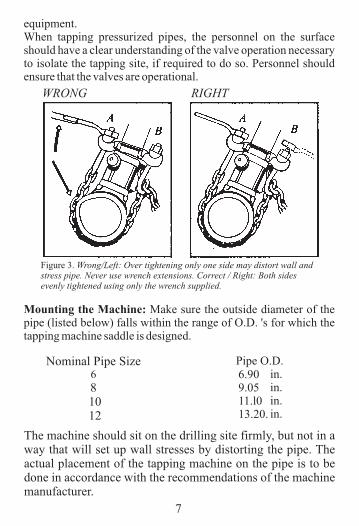
Mounting the Machine: Make sure the outside diameter of the pipe (listed below) falls within the range of O.D. 's for which the tapping machine saddle is designed.
Nominal Pipe Size68
10 12
Pipe O.D.
The machine should sit on the drilling site firmly, but not in a way that will set up wall stresses by distorting the pipe. The actual placement of the tapping machine on the pipe is to be done in accordance with the recommendations of the machine manufacturer.
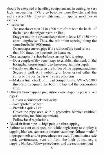
RIGHTWRONG
equipment.When tapping pressurized pipes, the personnel on the surface should have a clear understanding of the valve operation necessary to isolate the tapping site, if required to do so. Personnel should ensure that the valves are operational.
Figure 3. Wrong/Left: Over tightening only one side may distort wall and stress pipe. Never use wrench extensions. Correct / Right: Both sides evenly tightened using only the wrench supplied.
6.909.0511.l013.20.
in.in.in.in.
8
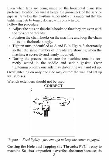
Even when taps are being made on the horizontal plane (the preferred location because it keeps the gooseneck of the service pipe as far below the frostline as possible) it is important that the tightening nuts be turned down evenly on each side.Follow this procedure:
Adjust the nuts on the chain hooks so that they are even with the tops of the threads.Position the chain hooks on the machine and loop the chain links into the hooks snugly.Tighten nuts indentified as A and B in Figure 3 alternately so that the same number of threads are showing when the machine is correctly and firmly mounted.During the process make sure the machine remains cor-rectly seated in the saddle and saddle gasket. Over tightening on only one side may distort the wall and set up.
Cutting the Hole and Tapping the Threads: machine. So it is a temptation to overfeed the cutter because it is
PVC is easy to
Overtightening on only one side may distort the wall and set up wall stresses.
•
•
•
•
Wrench extenders should not be used.CORRECT
Figure 4. Feed lightly—just enough to keep the cutter engaged.
9
comparatively easy to turn the ratchet handle. The principle is to allow the cutter to work as a cutter. Rotate the ratchet handle one complete turn for every one-eighth (1/8) turn of the feed yoke as shown in Figure 4.
The feed rate should be less in cold weather. Judge the correct feed rate by "finger pull"—the effort should be about the same as used to open a desk drawer. This rule of thumb applies in any temperature.
Upon wall penetration the upward thrust on the boring bar (as-suming a pressurized pipe) will be about 0.8 lb-force per 1 psi water pressure for a 1 - inch tap.
Use the feed yoke to engage the first few turns of the tapping tool in the hole. After this the tap is self-feeding and the feed yoke must be disengaged from the boring bar.
The "Cast Iron" mark on the boring bar is not a reliable indica-tor of how deep to tap. Tapping to the correct depth is important and should be determined by performing bench tests in advance and carefully noting the position of the top of the threaded feed sleeve, relative to the thrust collar or other datum point, when the corporation stop is correctly inserted.
As the tapping tool is reversed out of the hole, re-engage the feed yoke or hold the boring bar until the tap clears the threads. Release the bar slowly so as not the damage the threads, or in-jure the machine operator.
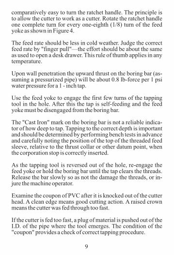
Examine the coupon of PVC after it is knocked out of the cutter head. A clean edge means good cutting action. A raised crown means the cutter was fed through too fast.
If the cutter is fed too fast, a plug of material is pushed out of the I.D. of the pipe where the tool emerges. The condition of the "coupon" provides a check of correct tapping procedure.
10
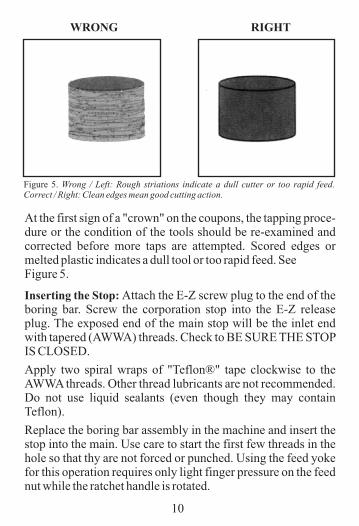
At the first sign of a "crown" on the coupons, the tapping proce-dure or the condition of the tools should be re-examined and corrected before more taps are attempted. Scored edges or melted plastic indicates a dull tool or too rapid feed. See Figure 5.
Inserting the Stop: Attach the E-Z screw plug to the end of the boring bar. Screw the corporation stop into the E-Z release plug. The exposed end of the main stop will be the inlet end with tapered (AWWA) threads. Check to BE SURE THE STOP IS CLOSED.
Apply two spiral wraps of "Teflon®" tape clockwise to the AWWA threads. Other thread lubricants are not recommended. Do not use liquid sealants (even though they may contain Teflon).
Replace the boring bar assembly in the machine and insert the stop into the main. Use care to start the first few threads in the hole so that thy are not forced or punched. Using the feed yoke for this operation requires only light finger pressure on the feed nut while the ratchet handle is rotated.
Figure 5. Wrong / Left: Rough striations indicate a dull cutter or too rapid feed. Correct / Right: Clean edges mean good cutting action.
WRONG RIGHT
11
Disengage the feed yoke and remove the ratchet handle as soon as the stop has firmly engaged the threads in the pipe wall. Com-plete the insertion using a torque wrench.
Tighten the stop to 27 foot-pounds (37 newton meters).
Snap the wrench counter clockwise to release the E-Z plug from the shaft or boring bar assembly. Remove the tapping machine in the usual way.
If there is leaking past the threads, tighten the stop to 35 foot-pounds. (48 newton meters). At correct insertion, 2-3 threads should be visible.
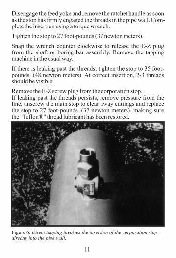
Remove the E-Z screw plug from the corporation stop.If leaking past the threads persists, remove pressure from the line, unscrew the main stop to clear away cuttings and replace the stop to 27 foot-pounds. (37 newton meters), making sure the "Teflon®" thread lubricant has been restored.
Figure 6. Direct tapping involves the insertion of the corporation stop directly into the pipe wall.
12
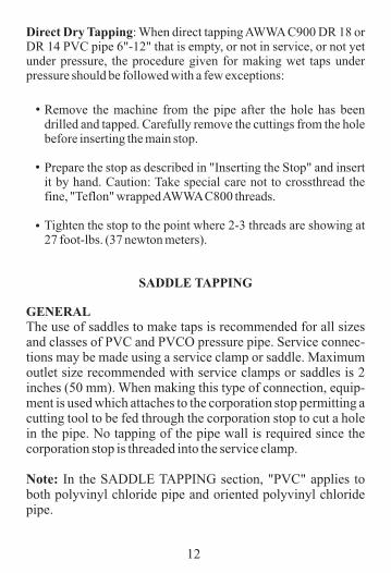
Direct Dry Tapping: When direct tapping AWWA C900 DR 18 or DR 14 PVC pipe 6"-12" that is empty, or not in service, or not yet under pressure, the procedure given for making wet taps under pressure should be followed with a few exceptions:
Remove the machine from the pipe after the hole has been drilled and tapped. Carefully remove the cuttings from the hole before inserting the main stop.
Prepare the stop as described in "Inserting the Stop" and insert it by hand. Caution: Take special care not to crossthread the fine, "Teflon" wrapped AWWA C800 threads.
Tighten the stop to the point where 2-3 threads are showing at 27 foot-lbs. (37 newton meters).
SADDLE TAPPING
GENERALThe use of saddles to make taps is recommended for all sizes and classes of PVC and PVCO pressure pipe. Service connec-tions may be made using a service clamp or saddle. Maximum outlet size recommended with service clamps or saddles is 2 inches (50 mm). When making this type of connection, equip-ment is used which attaches to the corporation stop permitting a cutting tool to be fed through the corporation stop to cut a hole in the pipe. No tapping of the pipe wall is required since the corporation stop is threaded into the service clamp.
Note: In the SADDLE TAPPING section, "PVC" applies to both polyvinyl chloride pipe and oriented polyvinyl chloride pipe.
•
•
•
13
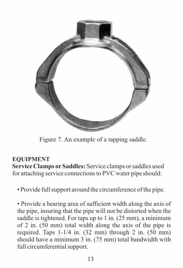
EQUIPMENTService Clamps or Saddles: for attaching service connections to PVC water pipe should:
Service clamps or saddles used
• Provide full support around the circumference of the pipe.
• Provide a bearing area of sufficient width along the axis of the pipe, insuring that the pipe will not be distorted when the saddle is tightened. For taps up to 1 in. (25 mm), a minimum of 2 in. (50 mm) total width along the axis of the pipe is required. Taps 1-1/4 in. (32 mm) through 2 in. (50 mm) should have a minimum 3 in. (75 mm) total bandwidth with full circumferential support.
Figure 7. An example of a tapping saddle.
14
Service Clamps should not:
Have lugs that will dig into the pipe when the saddle istightened.Have a U-bolt type of strap that does not provide sufficientbearing area.Have a clamping arrangement that is not fully contouredto the outside diameter of the pipe.
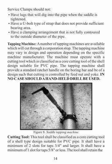
Tapping Machine: which will cut through a corporation stop. The tapping machine may vary in design and operation depending on the specific machine manufacturer. The machine must operate with a cutting tool which is classified as a core cutting tool of the shell design suitable for PVC pipe. The tapping machine shall provide a standard ratchet handle on the boring bar and be of a design such that cutting is controlled by feed nut and yoke. IN NO CASE SHOULD A HAND-HELD DRILL BE USED.
A number of tapping machines are available
Cutting Tool: of a shell type design suitable for PVC pipe. It shall have a minimum of 2 slots for taps 3/4" and larger. It shall have a minimum of 1 slot for taps 5/8" or less. The tool shall retain the
This tool shall be classified as a core cutting tool
Figure 8. Saddle tapping machine.
•
•
•
coupon. The shavings from the PVC wall being cut by the tool shall be directed into the throat of the shell cutter rather than being directed between the outside of the cutter and the hole being drilled. The tool shall be designed to accommodate the thickness of the wall being drilled through.
Many shell cutters are designed only for thin walled PVC. Consequently, they do not have sufficient throat depth to handle the heavier walled pipe. DO NOT DRILL A HOLE IN PVC PIPE WITH A TWIST DRILL OR AUGER BIT. The shank of the cutter must be adaptable to the cutting machine being used.
Corporation Stop: Because the corporation stop is inserted into the service clamp or saddle, it must have threads which match that of the clamp or saddle, which may be either IPS O.D. or C.I.O.D.
The maximum size of corporation stop which may be used with a service clamp or saddle is 2 inches. If a tap larger than 2 inches is required, a tapping sleeve and valve are required.
15
• Taps up to 2-inch maximum can be made through a saddle.
• Wet or dry taps (pipe filled or pipe empty) are allowed.• Placement
o
The spacing recommended for direct taps is conservative for a saddle tap.Tap not closer than 24-in. (600 mm) from both the back of the bell and the spigot insertion line.Stagger multiple taps and keep them at least 18" (450 mm) apart lengthwise. Thus, the minimum spacing along the same line is 36" (900 mm).Do not tap a curved pipe if the radius of the bend is less than 300 times the pipe outside diameter.
PROCEDURESPlanning the Saddle Tap:
—
—
—
—
16
Observe basic safety precautions when tapping pressurized pipes:
— Have a second worker close by.Wear protective gear.Provide a quick exit.Cover the pipe area with a protective blanket (without obstructing the machine operation).Follow local regulations.
Bleed air from pipes at high points before tapping.Failure to vent entrapped air, while neglecting to employ a tapping blanket, can create a more hazardous failure mode if improper tools and/or procedures are used. To maintain a safe work environment, vent air from the high points, use a tapping blanket, follow procedures, and use recommended equipment.
When tapping pressurized pipes, the personnel on the surface should have a clear understanding of the valve operation neces-sary to isolate the tapping site, if required to do so. Personnel should ensure that the valves are operational.
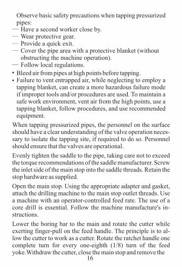
Evenly tighten the saddle to the pipe, taking care not to exceed the torque recommendations of the saddle manufacturer. Screw the inlet side of the main stop into the saddle threads. Retain the stop hardware as supplied.
Open the main stop. Using the appropriate adapter and gasket, attach the drilling machine to the main stop outlet threads. Use a machine with an operator-controlled feed rate. The use of a core drill is essential. Follow the machine manufacture's in-structions.
Lower the boring bar to the main and rotate the cutter while exerting finger-pull on the feed handle. The principle is to al-low the cutter to work as a cutter. Rotate the ratchet handle one complete turn for every one-eighth (1/8) turn of the feed yoke.Withdraw the cutter, close the main stop and remove the
•
———
—
•
drilling machine.TAPPING SLEEVE AND VALVE
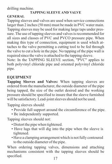
GENERALTapping sleeves and valves are used when service connections larger than 2 inches (50 mm) must be made in PVC water main. Tapping sleeves may be used for making large taps under pres-sure. The use of tapping sleeves and valves is recommended for all sizes and classes of PVC and PVCO pressure pipe. When making this type of connection, equipment is used which at-taches to the valve permitting a cutting tool to be fed through the valve to cut a hole in the pipe. No tapping of the pipe wall is required since the valve is attached to the tapping sleeve.Note: In the TAPPING SLEEVE section, "PVC" applies to both polyvinyl chloride pipe and oriented polyvinyl chloride pipe.
EQUIPMENTTapping Sleeves and Valves: When tapping sleeves are ordered from the manufacturer, the outside diameter of the pipe being tapped, the size of the outlet desired and the working pressure should be specified to insure that the sleeve furnished will be satisfactory. Lead-joint sleeves should not be used.
17
Tapping sleeves should:
When ordering tapping valves, dimensions and attaching mechanisms consistent with the tapping sleeves should be specified.
Tapping sleeves should not:
• Distort the pipe when tightened.• Have lugs that will dig into the pipe when the sleeve is tightened.
• Have a clamping arrangement which is not fully contouredto the outside diameter of the pipe.
o
o
• Provide full support around the circumference of the pipe.• Be independently supported.
18
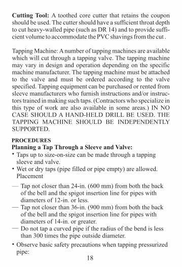
Cutting Tool: A toothed core cutter that retains the coupon should be used. The cutter should have a sufficient throat depth to cut heavy-walled pipe (such as DR 14) and to provide suffi-cient volume to accommodate the PVC shavings from the cut .
Tapping Machine: A number of tapping machines are available which will cut through a tapping valve. The tapping machine may vary in design and operation depending on the specific machine manufacturer. The tapping machine must be attached to the valve and must be ordered according to the valve specified. Tapping equipment can be purchased or rented from sleeve manufacturers who furnish instructions and/or instruc-tors trained in making such taps. (Contractors who specialize in this type of work are also available in some areas.) IN NO CASE SHOULD A HAND-HELD DRILL BE USED. THE TAPPING MACHINE SHOULD BE INDEPENDENTLY SUPPORTED.
PROCEDURESPlanning a Tap Through a Sleeve and Valve:•
—
Taps up to size-on-size can be made through a tapping sleeve and valve.Wet or dry taps (pipe filled or pipe empty) are allowed.Placement
Tap not closer than 24-in. (600 mm) from both the back of the bell and the spigot insertion line for pipes with diameters of 12-in. or less.Tap not closer than 36-in. (900 mm) from both the back of the bell and the spigot insertion line for pipes with diameters of 14-in. or greater.Do not tap a curved pipe if the radius of the bend is less than 300 times the pipe outside diameter.
•
—
—
Observe basic safety precautions when tapping pressurized pipe:
•
19
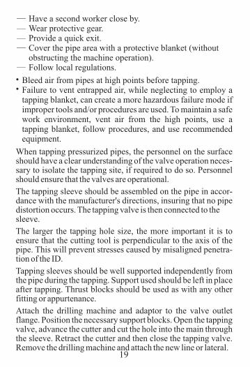
— Have a second worker close by.Wear protective gear.Provide a quick exit.Cover the pipe area with a protective blanket (without obstructing the machine operation).Follow local regulations.
———
—
• Bleed air from pipes at high points before tapping.Failure to vent entrapped air, while neglecting to employ a tapping blanket, can create a more hazardous failure mode if improper tools and/or procedures are used. To maintain a safe work environment, vent air from the high points, use a tapping blanket, follow procedures, and use recommended equipment.
•
When tapping pressurized pipes, the personnel on the surface should have a clear understanding of the valve operation neces-sary to isolate the tapping site, if required to do so. Personnel should ensure that the valves are operational.
The tapping sleeve should be assembled on the pipe in accor-dance with the manufacturer's directions, insuring that no pipe distortion occurs. The tapping valve is then connected to thesleeve.
The larger the tapping hole size, the more important it is to ensure that the cutting tool is perpendicular to the axis of the pipe. This will prevent stresses caused by misaligned penetra-tion of the ID.
Tapping sleeves should be well supported independently from the pipe during the tapping. Support used should be left in place after tapping. Thrust blocks should be used as with any other fitting or appurtenance.
Attach the drilling machine and adaptor to the valve outlet flange. Position the necessary support blocks. Open the tapping valve, advance the cutter and cut the hole into the main through the sleeve. Retract the cutter and then close the tapping valve. Remove the drilling machine and attach the new line or lateral.
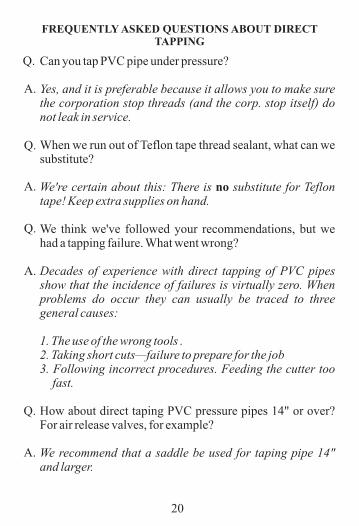
FREQUENTLY ASKED QUESTIONS ABOUT DIRECT TAPPING
20
Can you tap PVC pipe under pressure?
Yes, and it is preferable because it allows you to make sure the corporation stop threads (and the corp. stop itself) do not leak in service.
When we run out of Teflon tape thread sealant, what can we substitute?
We're certain about this: There is no substitute for Teflon tape! Keep extra supplies on hand.
We think we've followed your recommendations, but we had a tapping failure. What went wrong?
Decades of experience with direct tapping of PVC pipes show that the incidence of failures is virtually zero. When problems do occur they can usually be traced to three general causes:
1. The use of the wrong tools .2. Taking short cuts—failure to prepare for the job 3. Following incorrect procedures. Feeding the cutter too
fast.
How about direct taping PVC pressure pipes 14" or over? For air release valves, for example?
We recommend that a saddle be used for taping pipe 14" and larger.
oo
A.
A.
A.
A.
Q.
Q.
Q.
Q.
•
MEMBERS
CERTAINTEED
DIAMOND PLASTICS CORPORATION
IPEX, INC.
JM EAGLE
NATIONAL PIPE & PLASTICS
NORTH AMERICAN PIPE CORPORATION
PIPELIFE JET STREAM, INC.
ROYAL PIPE SYSTEMS
SANDERSON PIPE
UNI-BELL PVC PIPE ASSOCIATION2711 LBJ Freeway - Suite 1000 - Dallas, TX 75234
Phone (972) 243-3902, Fax (972) 243-3907www.uni-bell.org
UNI-PUB-8-10