TAP414-0: Electromagnetic induction, flux and flux linkage
66
Episode 414: Electromagnetic induction, flux and flux linkage Students will already have ideas about electromagnetic induction. In this episode, your task is to develop a picture of induction in which it is the cutting of lines of flux by a conductor that leads to an induced emf or current. Summary Student experiment: Wire, magnet, meter. (10 minutes) Discussion and demonstration: Induction effects. (20 minutes) Discussion: More about flux and flux linkage. (40 minutes) Student questions: On flux linkage. (20 minutes) Student experiments: Investigating induction. (20 minutes) Demonstrations: Related effects. (20 minutes) Student questions: Induced emfs. (30 minutes) Discussion and demonstration: Eddy currents. (20 minutes) Student questions: Eddy currents and Lenz's law. (20 minutes) Student experiment: Wire, magnet, meter Start with a simple experiment involving a coil of wire and a voltmeter. This will give you a chance to assess the knowledge that students bring to this section. TAP 414-1: Faraday’s law Discussion and demonstration: Induction effects 1 (resourcefulphysics .org)
Transcript of TAP414-0: Electromagnetic induction, flux and flux linkage
Episode 414: Electromagnetic induction, flux and flux linkage
Students will already have ideas about electromagnetic induction. In this episode, your task is to develop a picture of induction in which it is the cutting of lines of flux by a conductor that leads to an induced emf or current.
SummaryStudent experiment: Wire, magnet, meter. (10 minutes)Discussion and demonstration: Induction effects. (20 minutes)Discussion: More about flux and flux linkage. (40 minutes)Student questions: On flux linkage. (20 minutes)Student experiments: Investigating induction. (20 minutes)Demonstrations: Related effects. (20 minutes)Student questions: Induced emfs. (30 minutes)Discussion and demonstration: Eddy currents. (20 minutes)Student questions: Eddy currents and Lenz's law. (20 minutes)
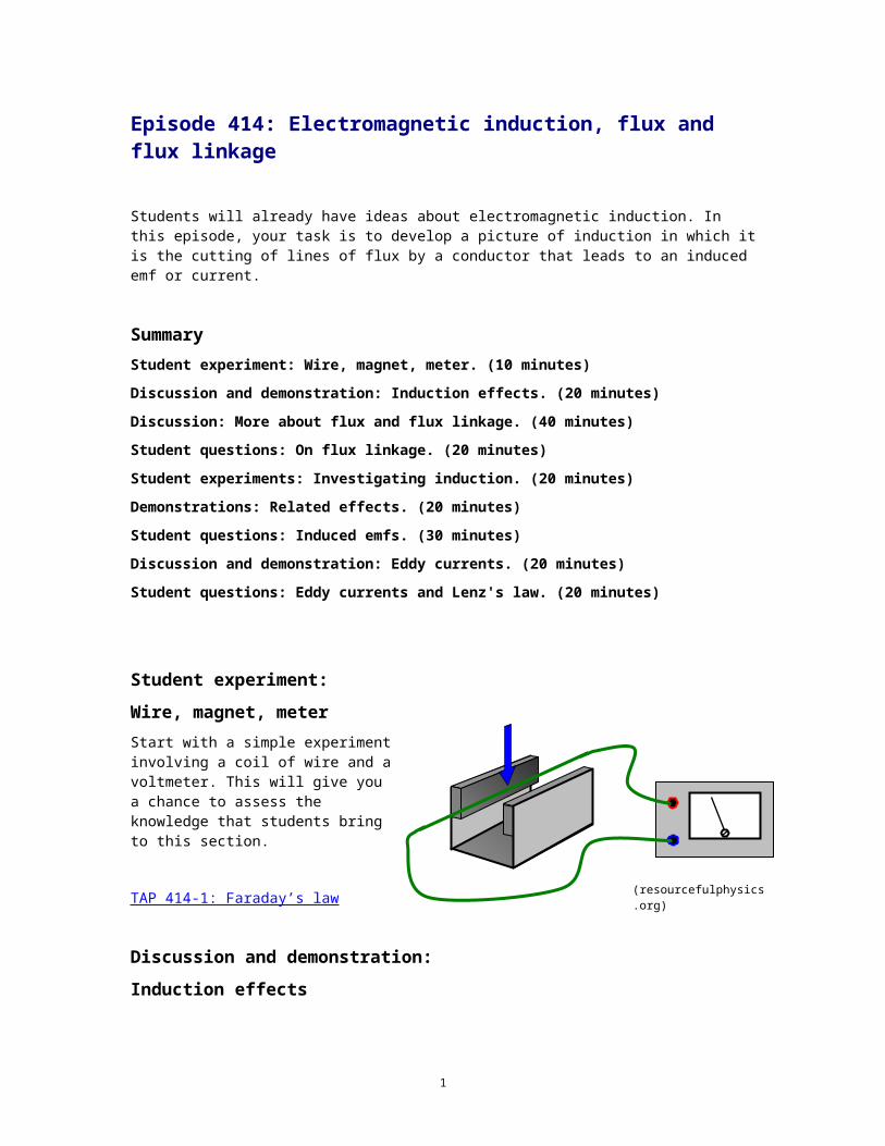
Student experiment:Wire, magnet, meterStart with a simple experiment involving a coil of wire and a voltmeter. This will give you a chance to assess the knowledge that students bring to this section.
TAP 414-1: Faraday’s law
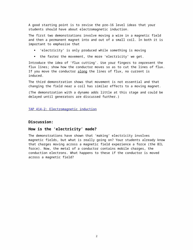
Discussion and demonstration:Induction effectsA good starting point is to revise the pre-16 level ideas that your students should have about electromagnetic induction.
The first two demonstrations involve moving a wire in a magnetic field and then a permanent magnet into and out of a small coil. In both it is important to emphasise that
‘electricity’ is only produced while something is moving
the faster the movement, the more ‘electricity’ we get.
Introduce the idea of ‘flux cutting’. Use your fingers to represent the flux lines; show how the conductor moves so as to cut the lines of flux. If you move the conductor along the lines of flux, no current is induced.
1
(resourcefulphysics.org)
The third demonstration shows that movement is not essential and that changing the field near a coil has similar effects to a moving magnet.
(The demonstration with a dynamo adds little at this stage and could be delayed until generators are discussed further.)
TAP 414-2: Electromagnetic induction
Discussion:How is the ‘electricity’ made?The demonstrations have shown that ‘making’ electricity involves magnetic fields, but what is really going on? Your students already know that charges moving across a magnetic field experience a force (the BIL force). Now, the metal of a conductor contains mobile charges, the conduction electrons. What happens to these if the conductor is moved across a magnetic field?
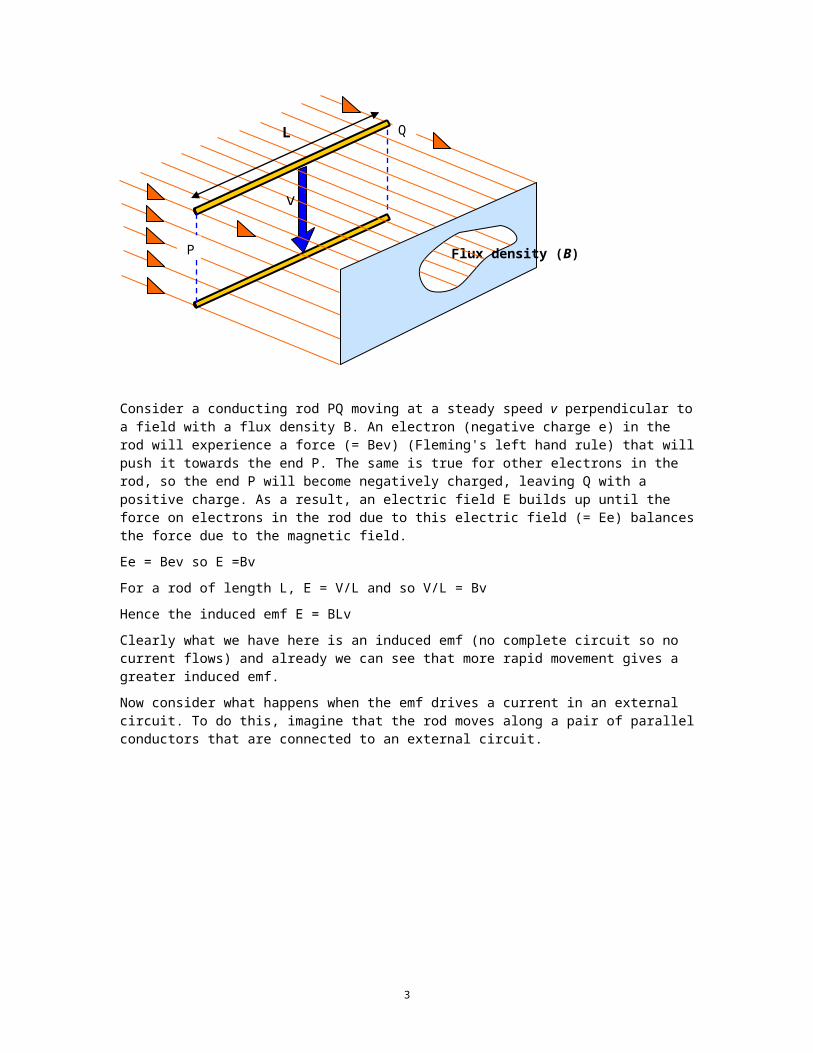
Consider a conducting rod PQ moving at a steady speed v perpendicular to a field with a flux density B. An electron (negative charge e) in the rod will experience a force (= Bev) (Fleming's left hand rule) that will push it towards the end P. The same is true for other electrons in the rod, so the end P will become negatively charged, leaving Q with a positive charge. As a result, an electric field E builds up until the force on electrons in the rod due to this electric field (= Ee) balances the force due to the magnetic field.
Ee = Bev so E =Bv
For a rod of length L, E = V/L and so V/L = Bv
Hence the induced emf E = BLv
Clearly what we have here is an induced emf (no complete circuit so no current flows) and already we can see that more rapid movement gives a greater induced emf.
Now consider what happens when the emf drives a current in an external circuit. To do this, imagine that the rod moves along a pair of parallel conductors that are connected to an external circuit.
Flux density (B)
v
L
2
P
Q
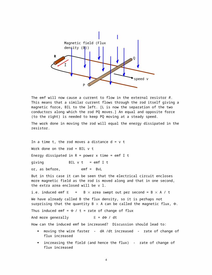
The emf will now cause a current to flow in the external resistor R. This means that a similar current flows through the rod itself giving a magnetic force, BIL to the left. [L is now the separation of the two conductors along which the rod PQ moves.] An equal and opposite force (to the right) is needed to keep PQ moving at a steady speed.
The work done in moving the rod will equal the energy dissipated in the resistor.
In a time t, the rod moves a distance d = v t
Work done on the rod = BIL v t
Energy dissipated in R = power x time = emf I t
giving BIL v t = emf I t
or, as before, emf = BvL
But in this case it can be seen that the electrical circuit encloses more magnetic field as the rod is moved along and that in one second, the extra area enclosed will be v l.
i.e. induced emf = B area swept out per second = B A / t
We have already called B the flux density, so it is perhaps not surprising that the quantity B A can be called the magnetic flux, .
Thus induced emf = / t = rate of change of flux
And more generally = d/ dt
How can the induced emf be increased? Discussion should lead to:
moving the wire faster - dA /dt increased - rate of change of flux increased
increasing the field (and hence the flux) - rate of change of flux increased
But there is a further possibility and this is to increase the number of turns of wire N in our circuit. By doing this, the flux has not been altered but the flux linkage (N ) will have increased. Hence it is more correct to say that
induced emf = rate of change of flux linkage
= N d/dt
This relationship is known as Faraday's law: -
3
P
speed v
QR
I
Magnetic field (Flux density (B))
when the flux linked with a circuit changes, the induced emf is proportional to the rate of change of flux linkage.
Finally, remind your students that the magnetic force on our simple generator (a) (b) was in a direction which would make the bar slow down unless an external force acted. This is an example of Lenz's law: -
the direction of the induced emf is such that it tends to oppose the motion or change causing it.
To include this idea in our formula, a minus sign has to be introduced, giving;
= – N d/dt
Discussion:More about flux and flux linkageWe have two formulae:
Flux, = BA
Flux linkage, N = NBA
When using these formulae, it is important to realise that B should be at right angles to the area A. If this is not the case, then it is the component of the field perpendicular to A that should be used.
Units: recall that the tesla (T) is defined from F = BIL, so 1 T = 1 N A-1 m-1.
The units for flux are thus N A-1 m. This unit is known as the Weber (Wb).
Flux linkage is measured in Weber-turns (Wb-turns).
Student questions:On flux linkageAlthough it is better to delay questions about Faraday's law until after more experimental work has been done, the relationship between flux, flux density and flux linkage should be reinforced with a question or two.
TAP 414-3: Sketching flux patterns
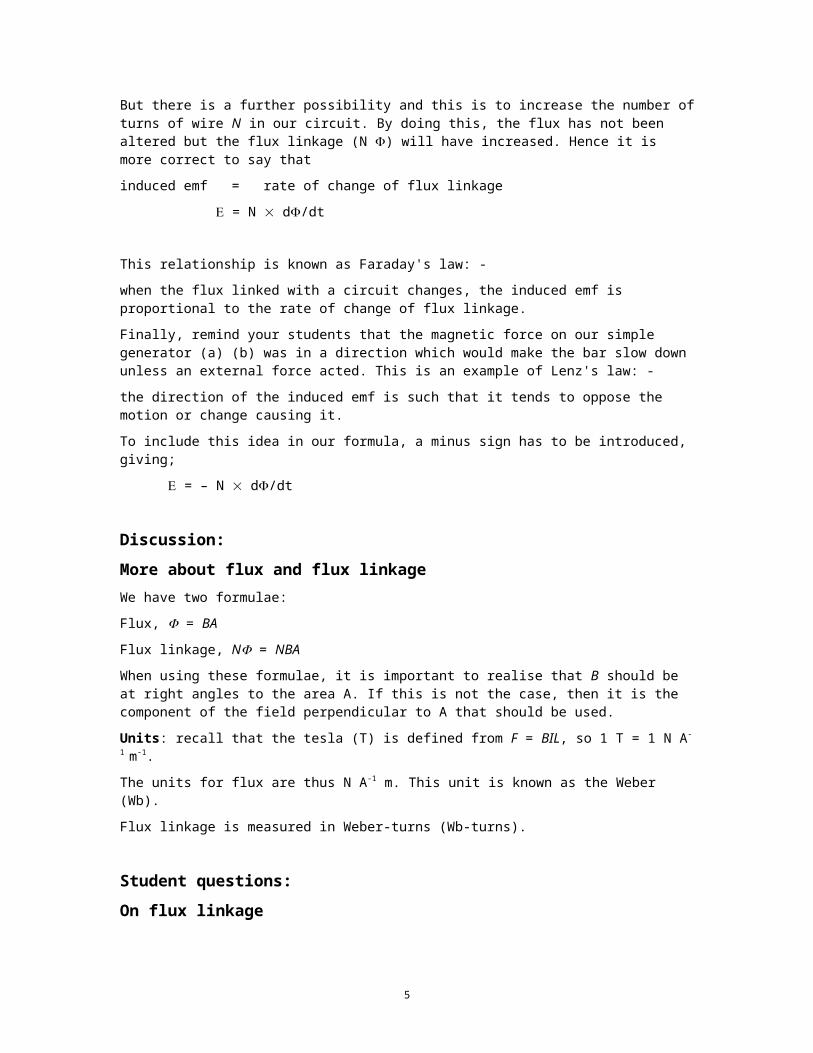
Student experiments:Investigating inductionTo support the theory, it is important that students look at electromagnetic induction experimentally in more detail than was met in the initial demonstration. What you choose to do will depend on what apparatus is available.
The experiment suggested here is based on coils (120/240 turns) linked by iron cores. Again the basics of Faraday's law are shown and there is a very strong lead into transformers.
TAP 414-4: Investigating electromagnetic induction
4
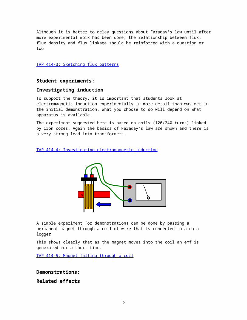
A simple experiment (or demonstration) can be done by passing a permanent magnet through a coil of wire that is connected to a data logger
This shows clearly that as the magnet moves into the coil an emf is generated for a short time.
TAP 414-5: Magnet falling through a coil
Demonstrations:Related effects
Some ideas for quick demonstrations of effects related to electromagnetic induction.
TAP 414-6: Quick demonstrations of electromagnetic induction.
Student questions:Induced emfs
The first link involves some qualitative work, sketching graphs and includes a falling magnet experiment
TAP 414-7: Rates of change
Some simple calculations.
TAP 414-8: Emf in an airliner
Discussion and demonstration:Eddy Currents
So far, the induced effects have been seen in wires with an associated change in flux. But does the conductor involved have to be a 'wire'? The answer is that there will be induced currents
5
N
whenever the flux linked with a conductor of any shape or size changes. If the conductor is not a wire, then these induced currents are referred to as 'eddy currents'.
Several demonstrations show the effect. From these experiments it should become clear that Lenz's law applies, i.e. the induced effects oppose the motion that is producing them. One of the main uses for eddy currents is in electromagnetic braking.
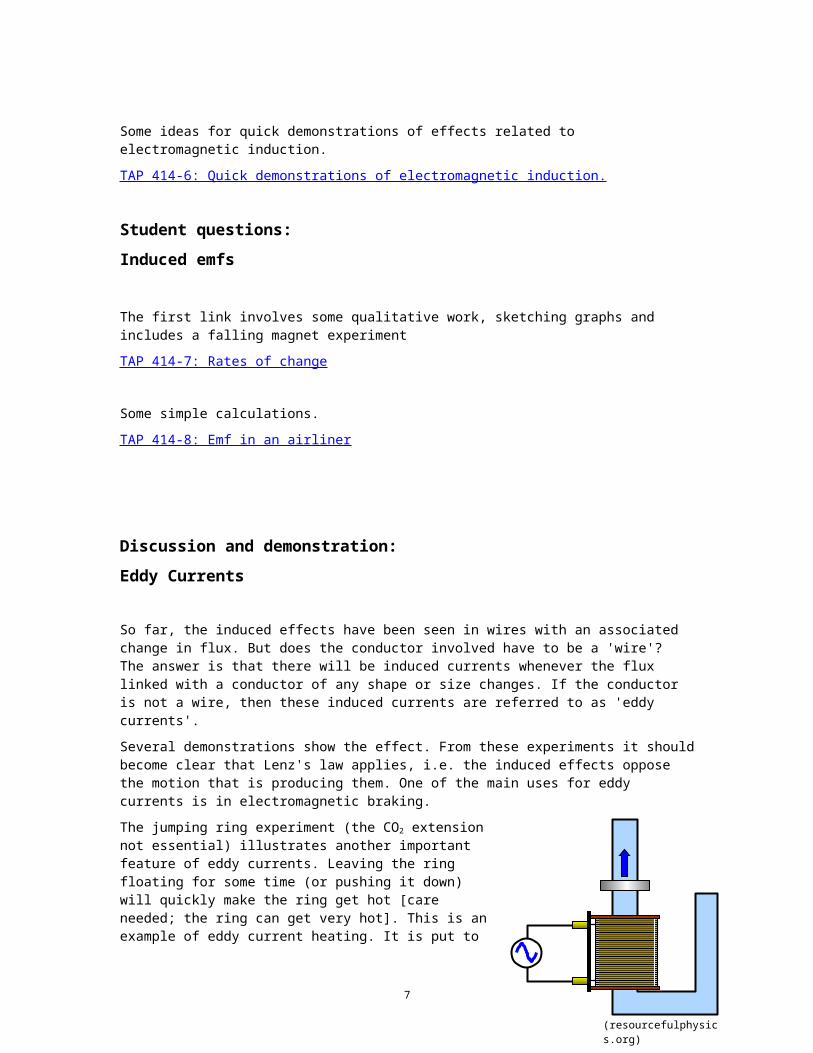
The jumping ring experiment (the CO2 extension not essential) illustrates another important feature of eddy currents. Leaving the ring floating for some time (or pushing it down) will quickly make the ring get hot [care needed; the ring can get very hot]. This is an example of eddy current heating. It is put to good practical use, e.g. in the production of pure alloys where eddy current heating of a metal crucible replaces a 'dirty' furnace. More frequently the heating is a nuisance as it wastes energy in electromagnetic machines.
TAP 414-9: Introducing eddy currents
TAP 414-10: Further eddy current demonstrations
Student questions:Eddy currents and Lenz's law
Some descriptive work can reinforce these ideas.
TAP 414-11: Eddy currents and Lenz’s law
6
(resourcefulphysics.org)
TAP 414-1: Faraday’s law
You will be making some general observations about Faraday’s law. For each experiment you will seek an explanation of what you see in terms of rate of change of flux. Look for a changing field, a conductor that can move or an area of flux linkage can change. All of these lead to a change of flux linkage.
You will need:
large horseshoe magnet
large coil of insulated copper wire
microvoltmeter
What to do
Connect the coil of wire to the microvoltmeter and place it close to the magnet.
1. Move the magnet next to the coil. What happens? How does it depend on speed and direction of movement?
2. Move the coil next to the magnet. What happens? How does it depend on speed and direction of movement?
3. Gradually unwind the coil in the magnetic field. What happens?
4. Take the coil and crumple it up, keeping it in the field. What happens?
What you have seen
1. An emf is induced if the coil or the magnet (or both) move.
2. The size of the induced emf depends on the speed of movement.
3. The direction of the induced emf depends on the direction of movement.
4. Changing the area or number of turns also changes the flux linkage, and so induces an emf.
7
Practical adviceMuch of this may be revision of pre-16 level work. Since the activity is dealt with in more detail later, it may be worth only a moment now.
Alternative approachesIf it seems appropriate, the following activity can be great fun and make the same point. Have a very long copper wire and connect it to a microvoltmeter. Get the class to take positions along the wire in a circle. As they perform the hokey-cokey an emf should be induced due to the movement of the conductor in the Earth’s field. Great fun and memorable.
Another impressive demonstration is to take an 1100-turn coil connected across the microvoltmeter. Rotating the coil in the Earth’s field is sufficient to cause significant deflections.
External referenceThis activity is taken from Advancing Physics chapter 15, 40E
8
TAP 414-2: Electromagnetic induction
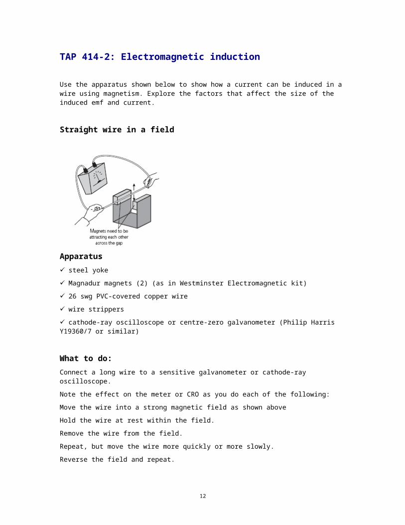
Use the apparatus shown below to show how a current can be induced in a wire using magnetism. Explore the factors that affect the size of the induced emf and current.
Straight wire in a field
Apparatussteel yoke
Magnadur magnets (2) (as in Westminster Electromagnetic kit)
26 swg PVC-covered copper wire
wire strippers
cathode-ray oscilloscope or centre-zero galvanometer (Philip Harris Y19360/7 or similar)
What to do:Connect a long wire to a sensitive galvanometer or cathode-ray oscilloscope.
Note the effect on the meter or CRO as you do each of the following:
Move the wire into a strong magnetic field as shown above
Hold the wire at rest within the field.
Remove the wire from the field.
Repeat, but move the wire more quickly or more slowly.
Reverse the field and repeat.
Make a loop in the wire and pass it over one of the magnetic poles so that two thicknesses of wire move through the field together.
Keep the wire still and move the magnet.
9

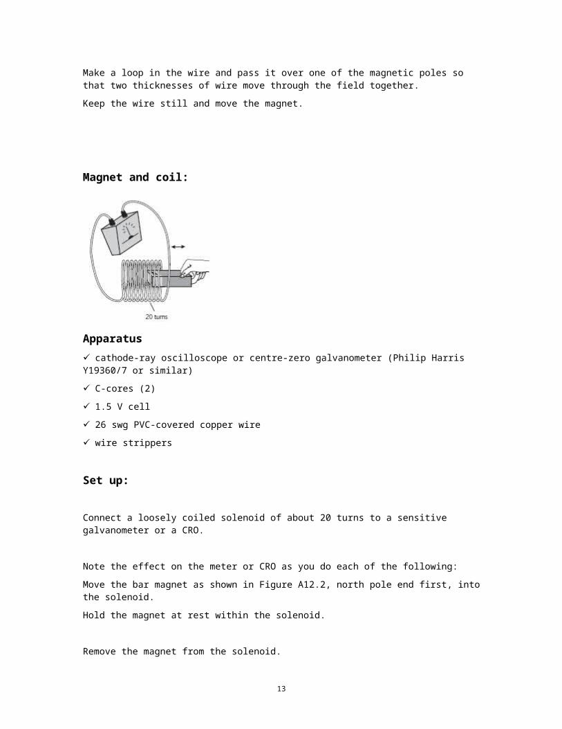
Magnet and coil:
Apparatuscathode-ray oscilloscope or centre-zero galvanometer (Philip Harris Y19360/7 or similar)
C-cores (2)
1.5 V cell
26 swg PVC-covered copper wire
wire strippers
Set up:
Connect a loosely coiled solenoid of about 20 turns to a sensitive galvanometer or a CRO.
Note the effect on the meter or CRO as you do each of the following:
Move the bar magnet as shown in Figure A12.2, north pole end first, into the solenoid.
Hold the magnet at rest within the solenoid.
Remove the magnet from the solenoid.
Repeat the previous steps, moving the magnet more quickly or more slowly.
Reverse the magnet so that the south pole points towards the coil.
Repeat the above steps.
Increase the number of turns of wire in the coil and repeat the previous steps.
Keep the magnet still and move the solenoid.
10
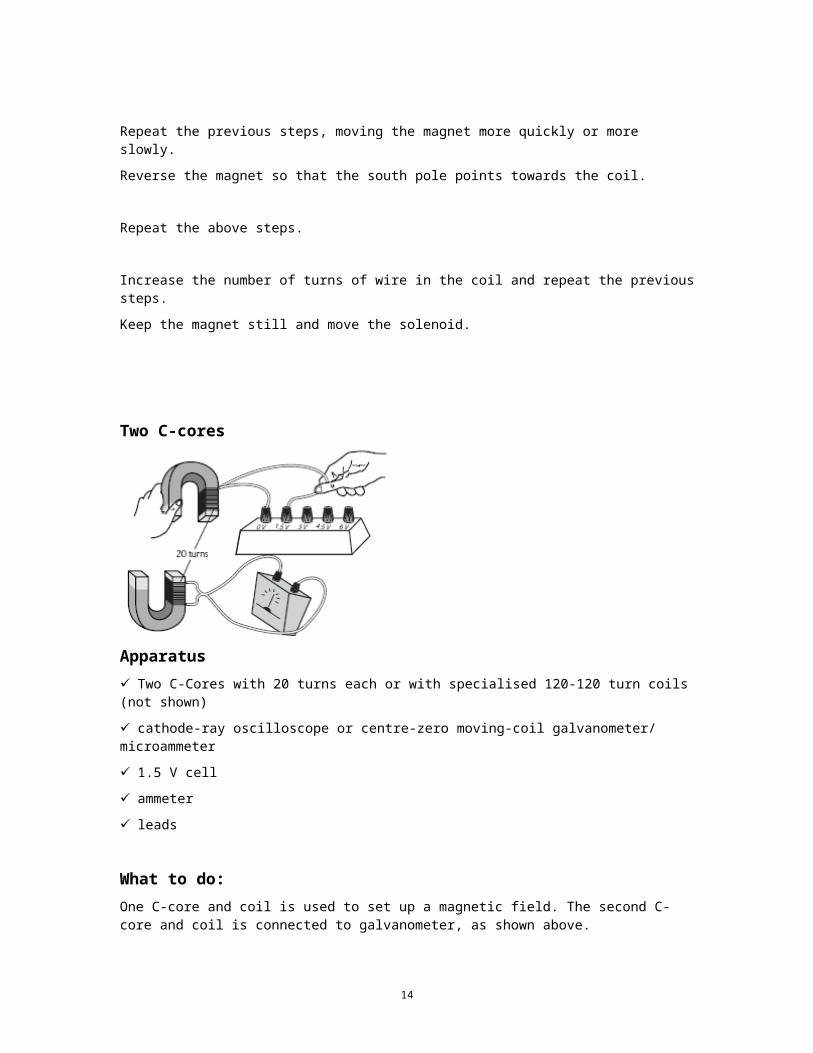
Two C-cores
ApparatusTwo C-Cores with 20 turns each or with specialised 120-120 turn coils (not shown)
cathode-ray oscilloscope or centre-zero moving-coil galvanometer/ microammeter
1.5 V cell
ammeter
leads
What to do:One C-core and coil is used to set up a magnetic field. The second C-core and coil is connected to galvanometer, as shown above.
Note the meter reading as you do each of the following:
Connect the ‘magnetic field’ solenoid to a single cell.
Leave the ‘field’ solenoid connected.
Disconnect the ‘field’ solenoid from the cell.
Change the separation of the solenoids and repeat.
What can you do to increase the size of the meter reading?
Dynamo
Apparatuscathode-ray oscilloscope
bicycle dynamo (mounted version that can be turned by hand)
leads
11
What to doConnect a bicycle dynamo to a CRO and observe the output as you rotate the dynamo at various speeds.
NoteNot all parts of this activity are equally reliable for quantitative results but you should be reasonably confident to say whether the induced emf increases or decreases with any or all of the variables.
12
Practical adviceIf time permits, we recommend that this is a class practical, but it could be a demonstration. These classic demonstrations are a little remote from the context, but they are nevertheless useful and thought-provoking and provide a useful lead in to a quantitative treatment of electromagnetic induction.
There is quite a lot of theory at this point, involving the key ideas of flux and flux linkage and leading up to Faraday’s law. To introduce Lenz’s law, an energy argument is used; we recommend discussing with students the consequences if the induced emf was in the reverse direction.
The case of an isolated straight wire moving in a magnetic field can be treated as a special case of Faraday’s law (i.e. rate of change of flux linkage), rather than in terms of ‘cutting’ field lines, since the latter approach obscures the fact that there is really only one law underlying electromagnetic induction, irrespective of how it is brought about.
Fleming’s right-hand rule could make an appearance here, following an argument in terms of Lenz’s law. One way to remember which hand to use is to note that (in the UK) motors drive on the left, so the left-hand rule applies to motors – and the other hand is for dynamos.
External referenceThis activity is taken from Salters Horners Advanced Physics, section TRA, activity 12
13
TAP 414-3: Sketching flux patterns
Learning typical shapes of magnetic fields Use the examples and guidelines suggested below to learn how to make a rough sketch of the expected shape of the magnetic fields of magnets and coils.
Flux goes with the flow Inside a magnet or a piece of magnetised material, the flux just follows the direction of magnetisation. It emerges from, and enters into, the iron at the poles. So start sketching at the poles, all flux lines are continuous. A line which emerges (conventionally at a north pole) enters the material again at the south pole. Flux lines never cross. Think of flux as like a fluid pumped out of N poles and sucked into S poles (although nothing is actually flowing or physically connected to the magnet etc)
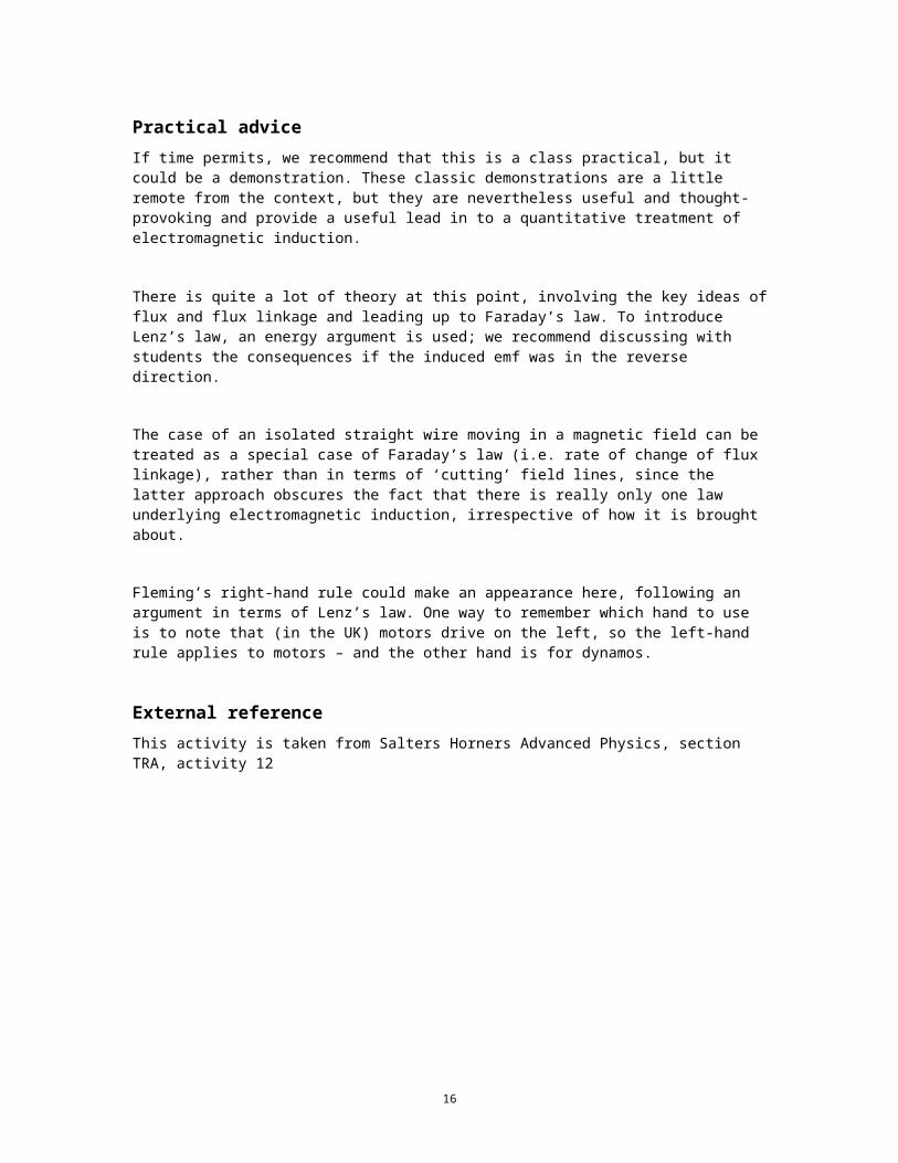
Here is a sketch of the flux from a short bar magnet:
1. Sketch the flux from a longer magnet, like this:
S N
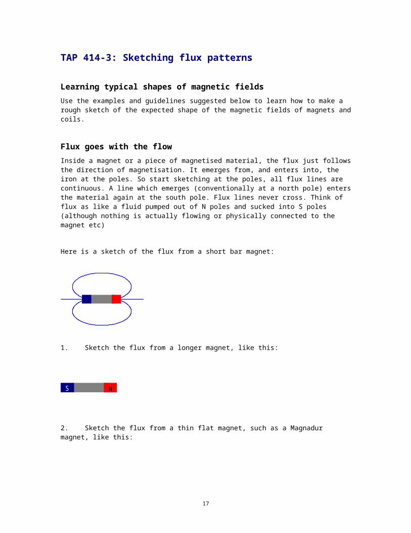
2. Sketch the flux from a thin flat magnet, such as a Magnadur magnet, like this:
N
S
14
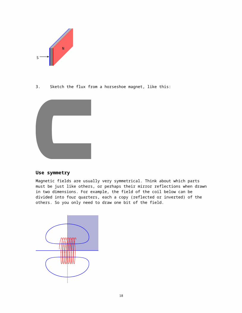
3. Sketch the flux from a horseshoe magnet, like this:
Use symmetry Magnetic fields are usually very symmetrical. Think about which parts must be just like others, or perhaps their mirror reflections when drawn in two dimensions. For example, the field of the coil below can be divided into four quarters, each a copy (reflected or inverted) of the others. So you only need to draw one bit of the field.
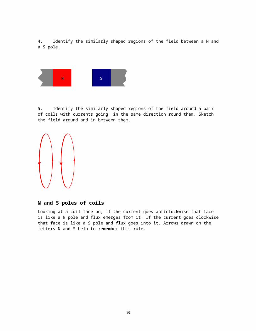
4. Identify the similarly shaped regions of the field between a N and a S pole.
SN
15
5. Identify the similarly shaped regions of the field around a pair of coils with currents going in the same direction round them. Sketch the field around and in between them.
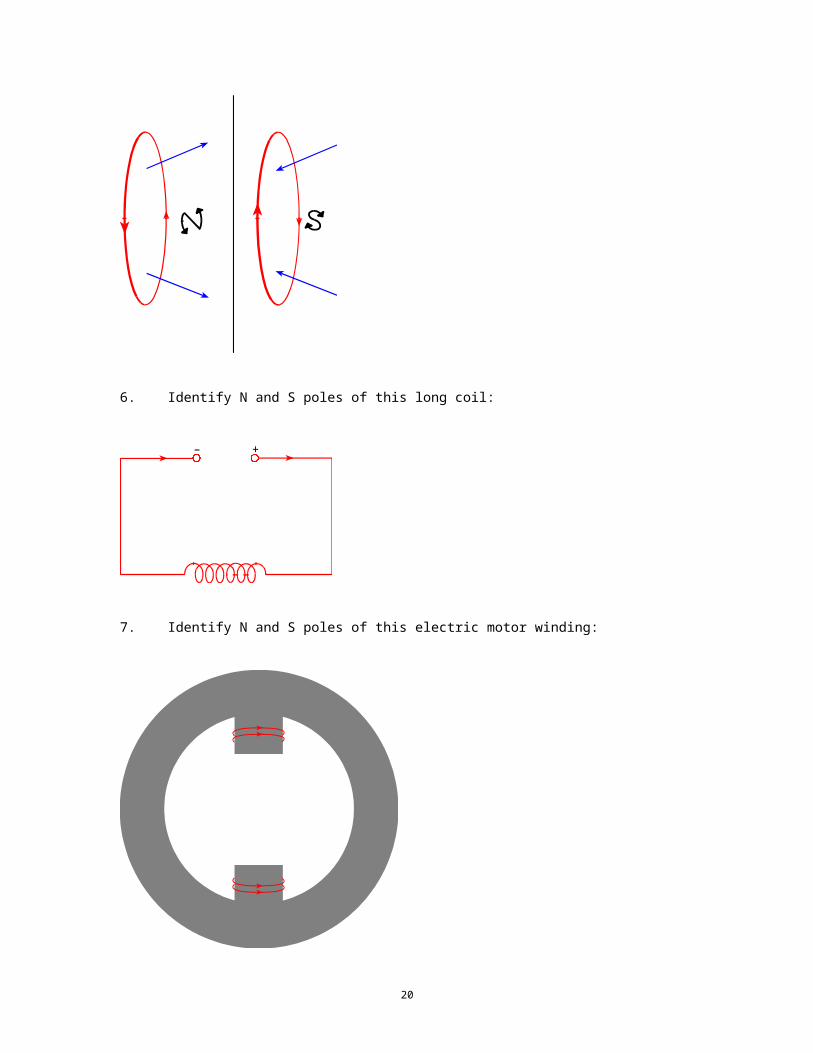
N and S poles of coils Looking at a coil face on, if the current goes anticlockwise that face is like a N pole and flux emerges from it. If the current goes clockwise that face is like a S pole and flux goes into it. Arrows drawn on the letters N and S help to remember this rule.
6. Identify N and S poles of this long coil:
– +
16
7. Identify N and S poles of this electric motor winding:
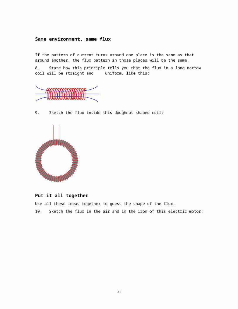
Same environment, same flux
If the pattern of current turns around one place is the same as that around another, the flux pattern in those places will be the same.
8. State how this principle tells you that the flux in a long narrow coil will be straight and uniform, like this:
9. Sketch the flux inside this doughnut shaped coil:
17
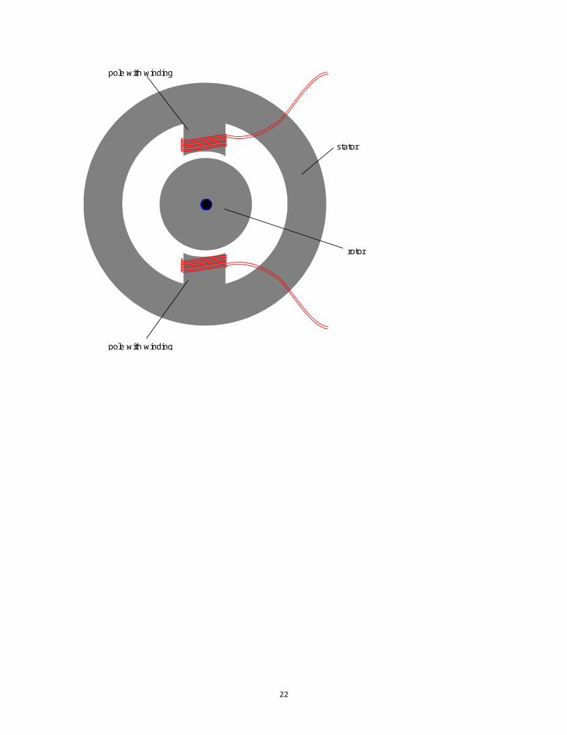
Put it all together Use all these ideas together to guess the shape of the flux.
10. Sketch the flux in the air and in the iron of this electric motor:
rotor
pole with winding
pole with winding
stator
18
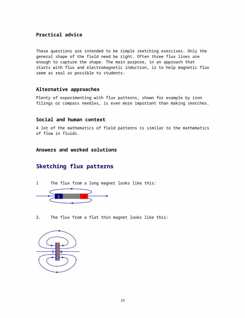
Practical advice
These questions are intended to be simple sketching exercises. Only the general shape of the field need be right. Often three flux lines are enough to capture the shape. The main purpose, in an approach that starts with flux and electromagnetic induction, is to help magnetic flux seem as real as possible to students.
Alternative approachesPlenty of experimenting with flux patterns, shown for example by iron filings or compass needles, is even more important than making sketches.
Social and human contextA lot of the mathematics of field patterns is similar to the mathematics of flow in fluids.
Answers and worked solutions
Sketching flux patterns
1 The flux from a long magnet looks like this:
NS
2. The flux from a flat thin magnet looks like this:
NS
19
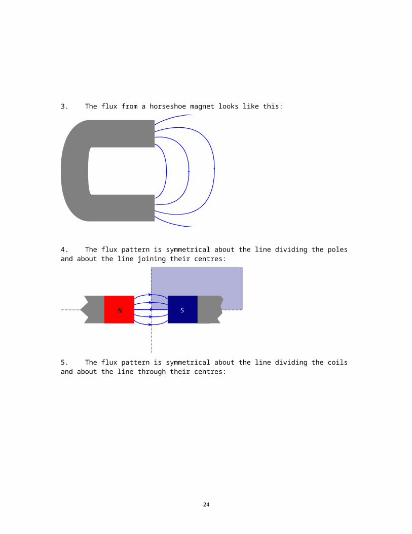
3. The flux from a horseshoe magnet looks like this:
4. The flux pattern is symmetrical about the line dividing the poles and about the line joining their centres:
SN
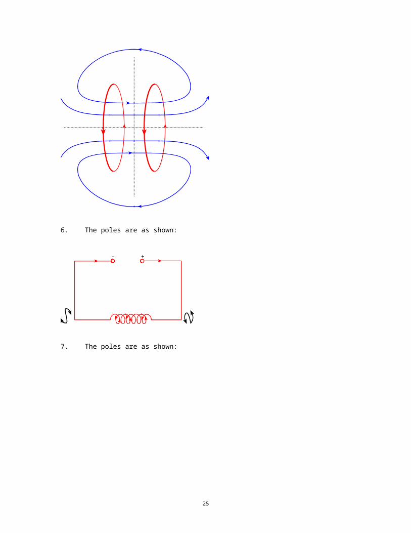
5. The flux pattern is symmetrical about the line dividing the coils and about the line through their centres:
20
6. The poles are as shown:
– +
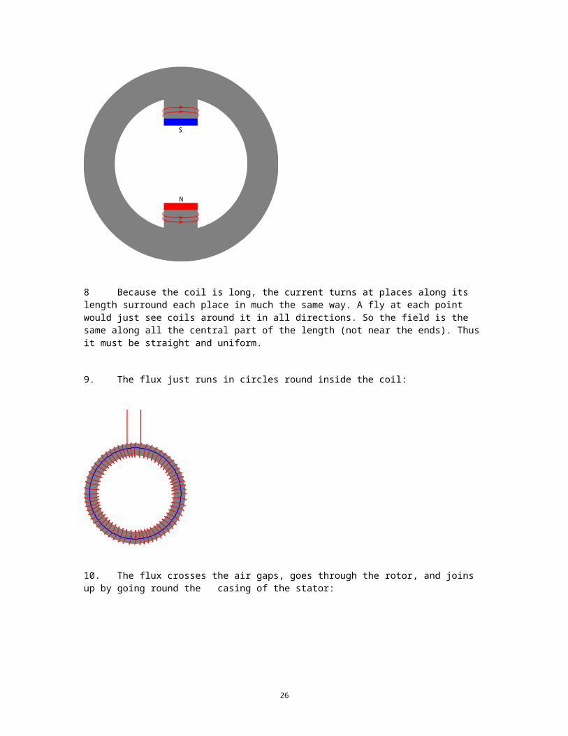
7. The poles are as shown:
S
N
8 Because the coil is long, the current turns at places along its length surround each place in much the same way. A fly at each point would just see coils around it in all directions. So the field is the same along all the central part of the length (not near the ends). Thus it must be straight and uniform.
9. The flux just runs in circles round inside the coil:
21
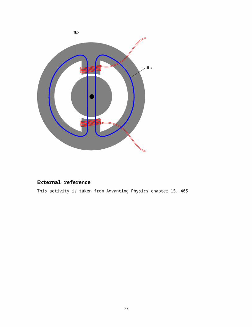
10. The flux crosses the air gaps, goes through the rotor, and joins up by going round the casing of the stator:
flux
flux
External referenceThis activity is taken from Advancing Physics chapter 15, 40S
22
TAP 414- 4: Investigating electromagnetic induction
Inducing emfs
Oersted had demonstrated that an electric current produced a magnetic field. Faraday suspected that a magnetic field would produce an electric current. Others worked on this problem as well, most notably Joseph Henry in the USA. The major breakthrough was to see that it was changing magnetic fields that induce an electric field, not static ones.
You will need: two 240-turn coils
two C-cores
mild steel bar, 30 cm long
about eight 4 mm leads
microvoltmeter
spst switch
power supply, 5 V dc
signal generator
oscilloscope
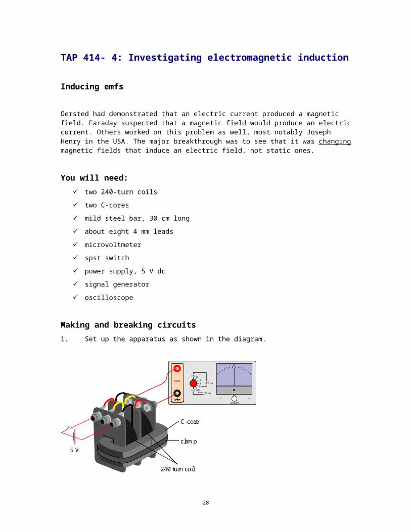
Making and breaking circuits 1. Set up the apparatus as shown in the diagram.
clamp
C-core
5 V
240 turn coil
2. Close the switch. What happens?
3. Open the switch again. Is that what you expected?
23
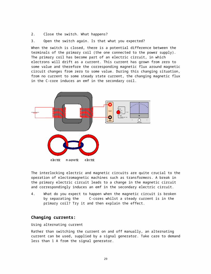
When the switch is closed, there is a potential difference between the terminals of the primary coil (the one connected to the power supply). The primary coil has become part of an electric circuit, in which electrons will drift as a current. This current has grown from zero to some value and therefore the corresponding magnetic flux around magnetic circuit changes from zero to some value. During this changing situation, from no current to some steady state current, the changing magnetic flux in the C-core induces an emf in the secondary coil.
electric magnetic electric
The interlocking electric and magnetic circuits are quite crucial to the operation of electromagnetic machines such as transformers. A break in the primary electric circuit leads to a change in the magnetic circuit and correspondingly induces an emf in the secondary electric circuit.
4. What do you expect to happen when the magnetic circuit is broken by separating the C-cores whilst a steady current is in the primary coil? Try it and then explain the effect.
Changing currents:Using alternating current
Rather than switching the current on and off manually, an alternating current can be used, supplied by a signal generator. Take care to demand less than 1 A from the signal generator.
24
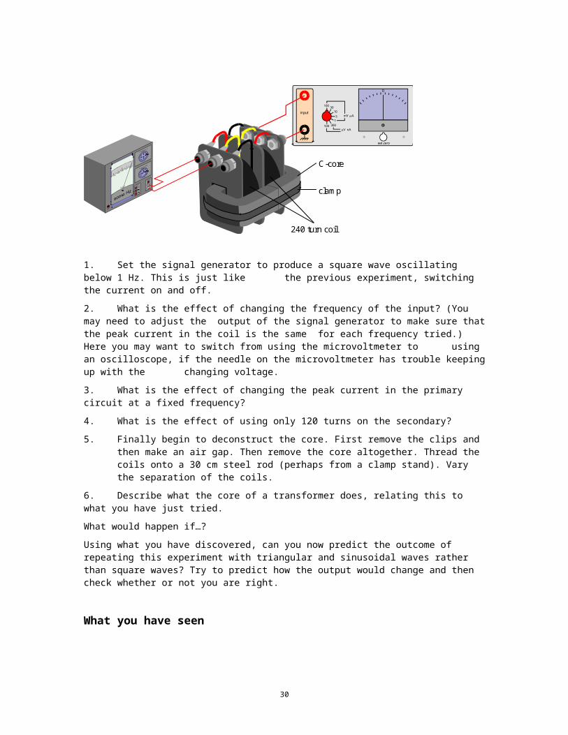
clamp
C-core
240 turn coil
1. Set the signal generator to produce a square wave oscillating below 1 Hz. This is just like the previous experiment, switching the current on and off.
2. What is the effect of changing the frequency of the input? (You may need to adjust the output of the signal generator to make sure that the peak current in the coil is the same for each frequency tried.) Here you may want to switch from using the microvoltmeter to using an oscilloscope, if the needle on the microvoltmeter has trouble keeping up with the changing voltage.
3. What is the effect of changing the peak current in the primary circuit at a fixed frequency?
4. What is the effect of using only 120 turns on the secondary?
5. Finally begin to deconstruct the core. First remove the clips and then make an air gap. Then remove the core altogether. Thread the coils onto a 30 cm steel rod (perhaps from a clamp stand). Vary the separation of the coils.
6. Describe what the core of a transformer does, relating this to what you have just tried.
What would happen if…?
Using what you have discovered, can you now predict the outcome of repeating this experiment with triangular and sinusoidal waves rather than square waves? Try to predict how the output would change and then check whether or not you are right.
What you have seen
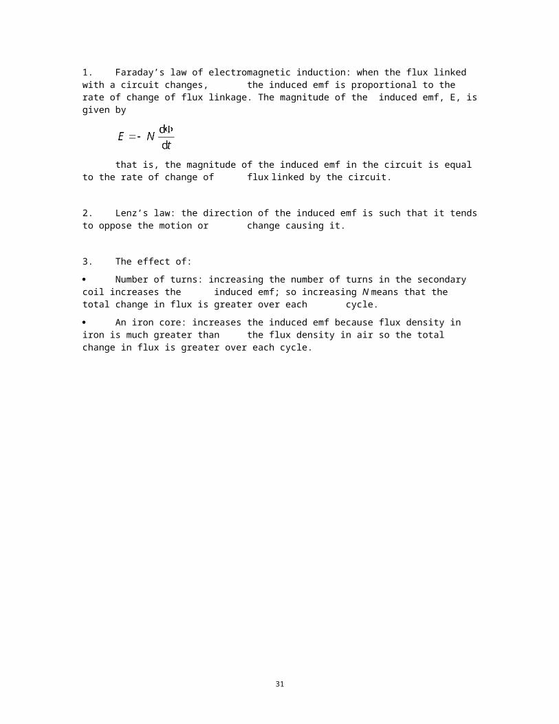
1. Faraday’s law of electromagnetic induction: when the flux linked with a circuit changes, the induced emf is proportional to the rate of change of flux linkage. The magnitude of the induced emf, E, is given by
that is, the magnitude of the induced emf in the circuit is equal to the rate of change of flux linked by the circuit.
2. Lenz’s law: the direction of the induced emf is such that it tends to oppose the motion or change causing it.
25
3. The effect of:
Number of turns: increasing the number of turns in the secondary coil increases the induced emf; so increasing N means that the total change in flux is greater over each cycle.
An iron core: increases the induced emf because flux density in iron is much greater than the flux density in air so the total change in flux is greater over each cycle.
26
Practical adviceThis is a quite crucial demonstration or experiment to help students become familiar with Faraday’s law and Lenz’s law and the action of a transformer. It could be tackled in a number of different ways. It can work with the class all gathered round as a demonstration discussion. It is unlikely to be the case that there are enough meters to allow class experimentation so the only other choice is to arrange for each group of students to tackle the experiment in turn. If there do happen to be two suitable voltmeters then one can be connected to the primary side of the circuit for comparison. This is a very elegant demonstration.
In the first part, students should see that it is a change in the magnetic flux that induces the emf. Making or breaking either the primary electric or the magnetic circuit will achieve this and induce an emf in the secondary.
Alternative approachesIt may be that oscilloscopes are available in larger numbers than microvoltmeters. If that is the case the experiment can be done with a primary solenoid with about 10 turns of wire wrapped round it as a secondary. One of the oscilloscope inputs is connected across a 15 W resistor and essentially displays the signal in the solenoid, which comes from the low-impedance output of a signal generator. This beam is used to trigger the time-base. The other input is connected to a ten-turn coil wrapped around the centre of the solenoid. Using the oscilloscope may well display the phase differences between primary and secondary more clearly than they can be seen using the meters, and make a better link with drawing graphs of varying current, flux and induced emf.
Social and human contextChanging magnetic fields are required to induce emfs; that this was not discovered earlier may seem remarkable to students. Faraday worked on the problem intermittently during the 1820s, finally publishing his result in 1831. Henry had probably discovered the effect a couple of years earlier but not published his discovery. Just what was the problem? Well, two issues could emerge. One is that things are rarely as obvious as they seem from the retrospective view of school science. The other is technological. One very real problem was getting insulated wire. Faraday built much of his own apparatus and insulated wire by wrapping calico around it by hand. The experiments were not quite so easy technically as we show them in the lab today.
External referenceThis activity is taken from Advancing Physics chapter 15, 70E
27
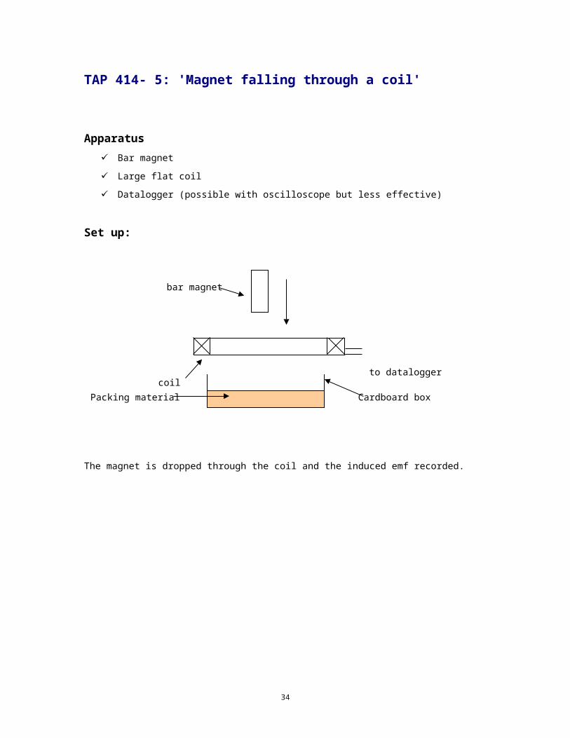
TAP 414- 5: 'Magnet falling through a coil'
Apparatus Bar magnet
Large flat coil
Datalogger (possible with oscilloscope but less effective)
Set up:
The magnet is dropped through the coil and the induced emf recorded.
to dataloggercoil
bar magnet
Cardboard boxPacking material
28
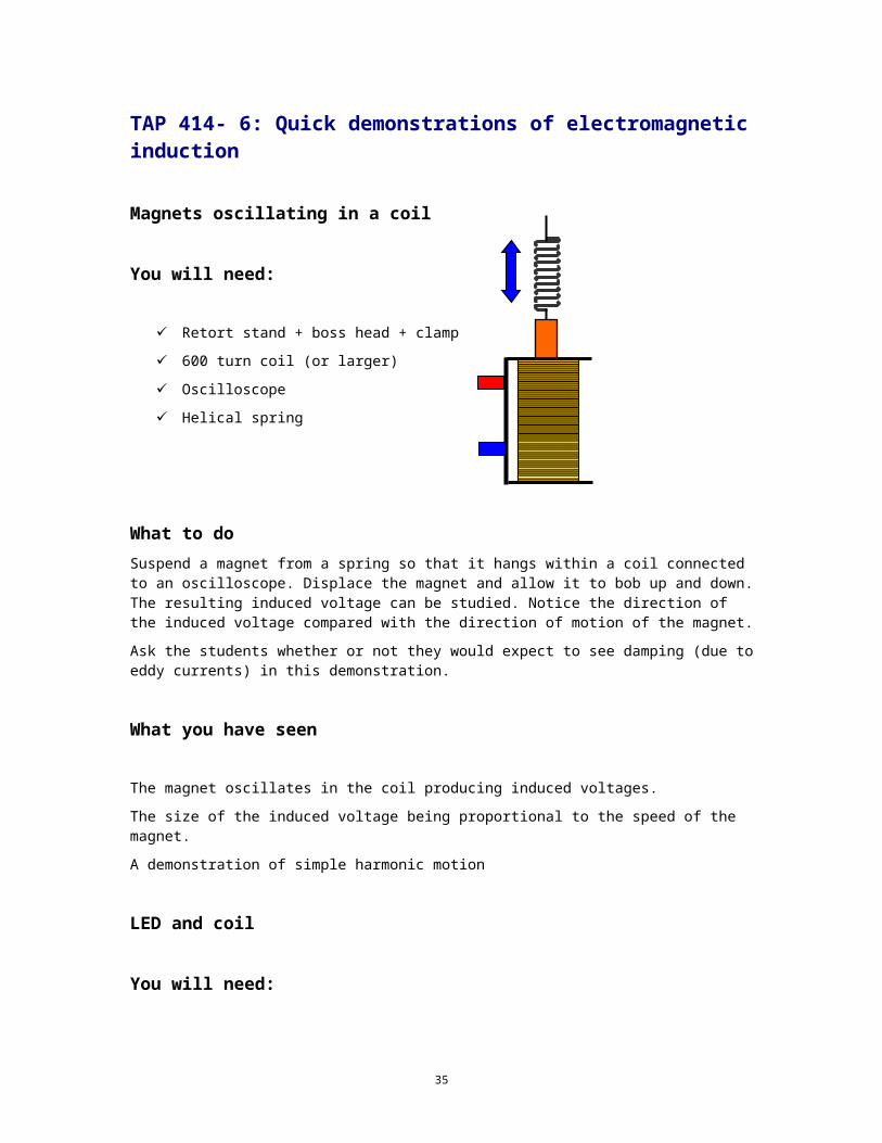
TAP 414- 6: Quick demonstrations of electromagnetic induction
Magnets oscillating in a coil
You will need:
Retort stand + boss head + clamp
600 turn coil (or larger)
Oscilloscope
Helical spring
What to do Suspend a magnet from a spring so that it hangs within a coil connected to an oscilloscope. Displace the magnet and allow it to bob up and down. The resulting induced voltage can be studied. Notice the direction of the induced voltage compared with the direction of motion of the magnet.
Ask the students whether or not they would expect to see damping (due to eddy currents) in this demonstration.
What you have seen
The magnet oscillates in the coil producing induced voltages.
The size of the induced voltage being proportional to the speed of the magnet.
A demonstration of simple harmonic motion
LED and coil
You will need:
two low current LEDs
large coil of insulated copper wire e.g. 1100 turns
a strong magnet
29
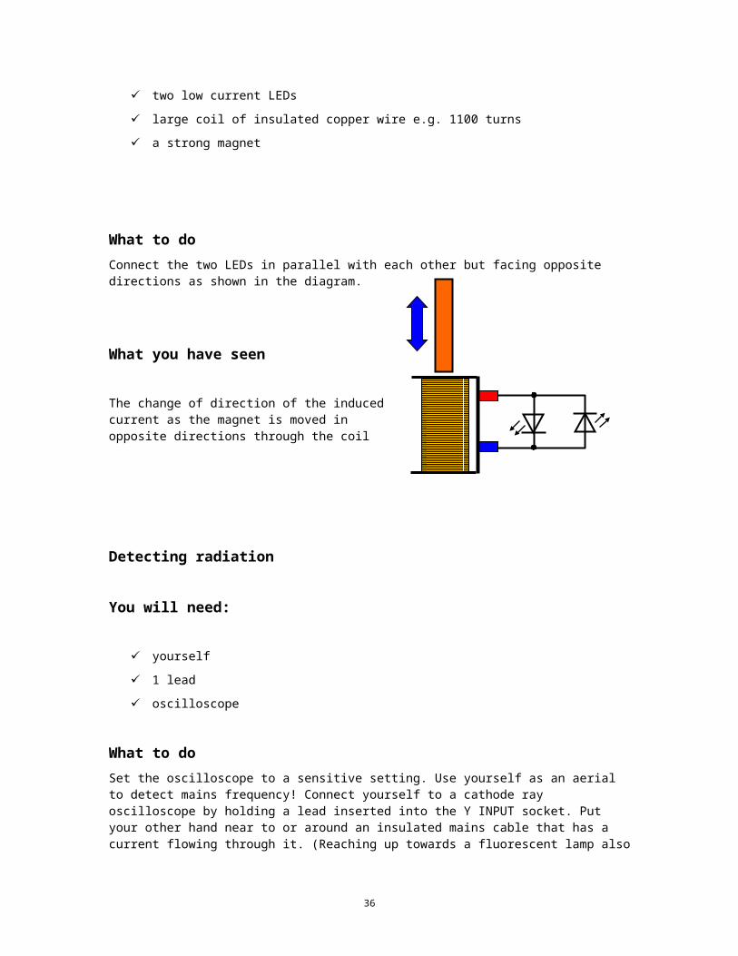
What to do Connect the two LEDs in parallel with each other but facing opposite directions as shown in the diagram.
What you have seen
The change of direction of the induced current as the magnet is moved in opposite directions through the coil
Detecting radiation
You will need:
yourself
1 lead
oscilloscope
What to do Set the oscilloscope to a sensitive setting. Use yourself as an aerial to detect mains frequency! Connect yourself to a cathode ray oscilloscope by holding a lead inserted into the Y INPUT socket. Put your other hand near to or around an insulated mains cable that has a current flowing through it. (Reaching up towards a fluorescent lamp also works). You will see an ac trace of frequency 50 Hz on the oscilloscope screen.
Tape recorder simulation
You will need:
3600 turn coil
at least ten Magnadur magnets
amplifier
speaker or oscilloscope
30
What to do
Induced voltages can be shown in this simple simulation of the action of the playback head in a tape recorder. Move a 3600 turn coil over a row of ceramic Magnadur magnets placed flat down on the bench with their poles alternately N - S face up with the coil connected to an amplifier and speaker or to an oscilloscope
What you will see
As the coil moves a changing voltage will be induced in it and this can be detected by the speaker or oscilloscope.
31
Practical adviceThese are intended to be quick demonstrations and so should be set up in advance
External ReferenceThis activity is taken from Resourceful Physics
32
Tap 414- 7: Rates of change
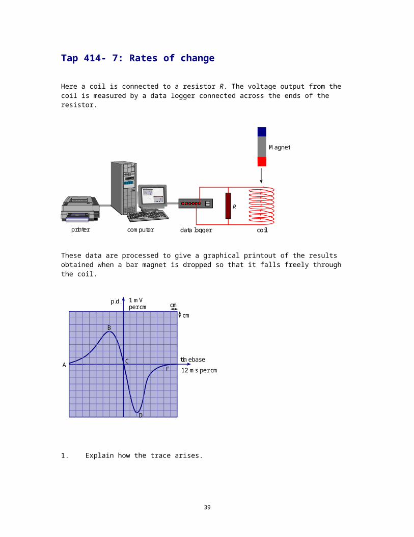
Here a coil is connected to a resistor R. The voltage output from the coil is measured by a data logger connected across the ends of the resistor.
Graph
Grap h
R
coil
Magnet
computer data loggerprinter
These data are processed to give a graphical printout of the results obtained when a bar magnet is dropped so that it falls freely through the coil.
B
CE
timebase
12 ms per cm
D
p.d. 1 mVper cm cm
cm
A
1. Explain how the trace arises.
33
2. Explain why the curve slopes upwards from A to B.
3. Explain why the voltage shown at B has a smaller magnitude than the voltage shown at D.
4. Explain why the graph has a positive and a negative section.
5. The areas under the two segments of the curve are the same. Explain why this is so.
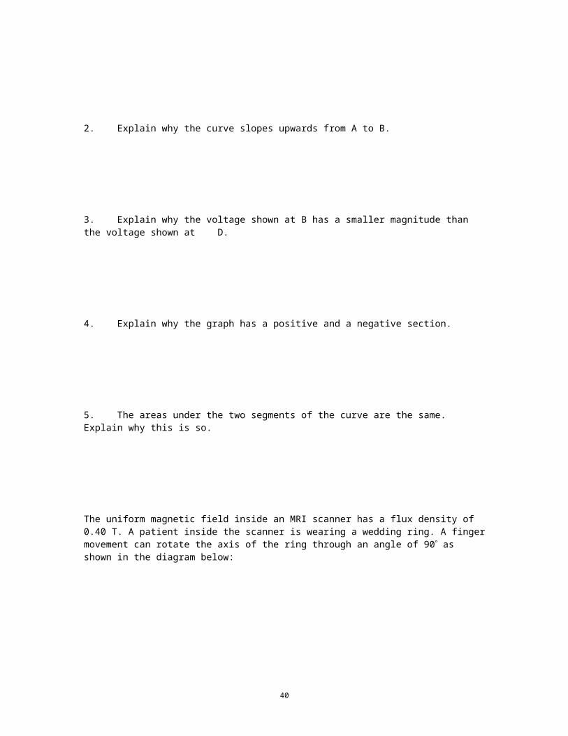
The uniform magnetic field inside an MRI scanner has a flux density of 0.40 T. A patient inside the scanner is wearing a wedding ring. A finger movement can rotate the axis of the ring through an angle of 90 as shown in the diagram below:
6. Calculate the average voltage induced in the ring if the ring diameter is 20 mm and the finger movement is completed in a time of 0.30 s.
34
7. Describe how the ring must move if there is to be no induced voltage.
The next questions are about a student’s investigation of the magnetic flux in an iron rod.
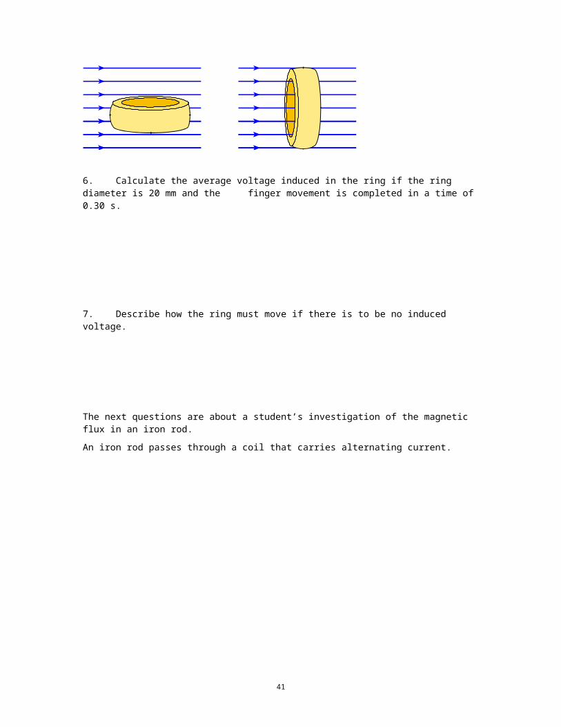
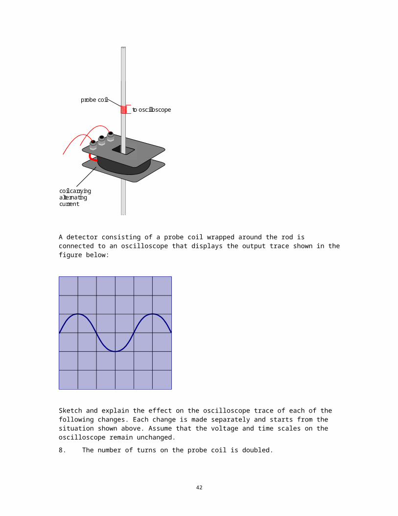
An iron rod passes through a coil that carries alternating current.
coil carryingalternatingcurrent
probe coil
to oscilloscope
A detector consisting of a probe coil wrapped around the rod is connected to an oscilloscope that displays the output trace shown in the figure below:
35
Sketch and explain the effect on the oscilloscope trace of each of the following changes. Each change is made separately and starts from the situation shown above. Assume that the voltage and time scales on the oscilloscope remain unchanged.
8. The number of turns on the probe coil is doubled.
9. The probe coil is positioned at the top of the rod.
36
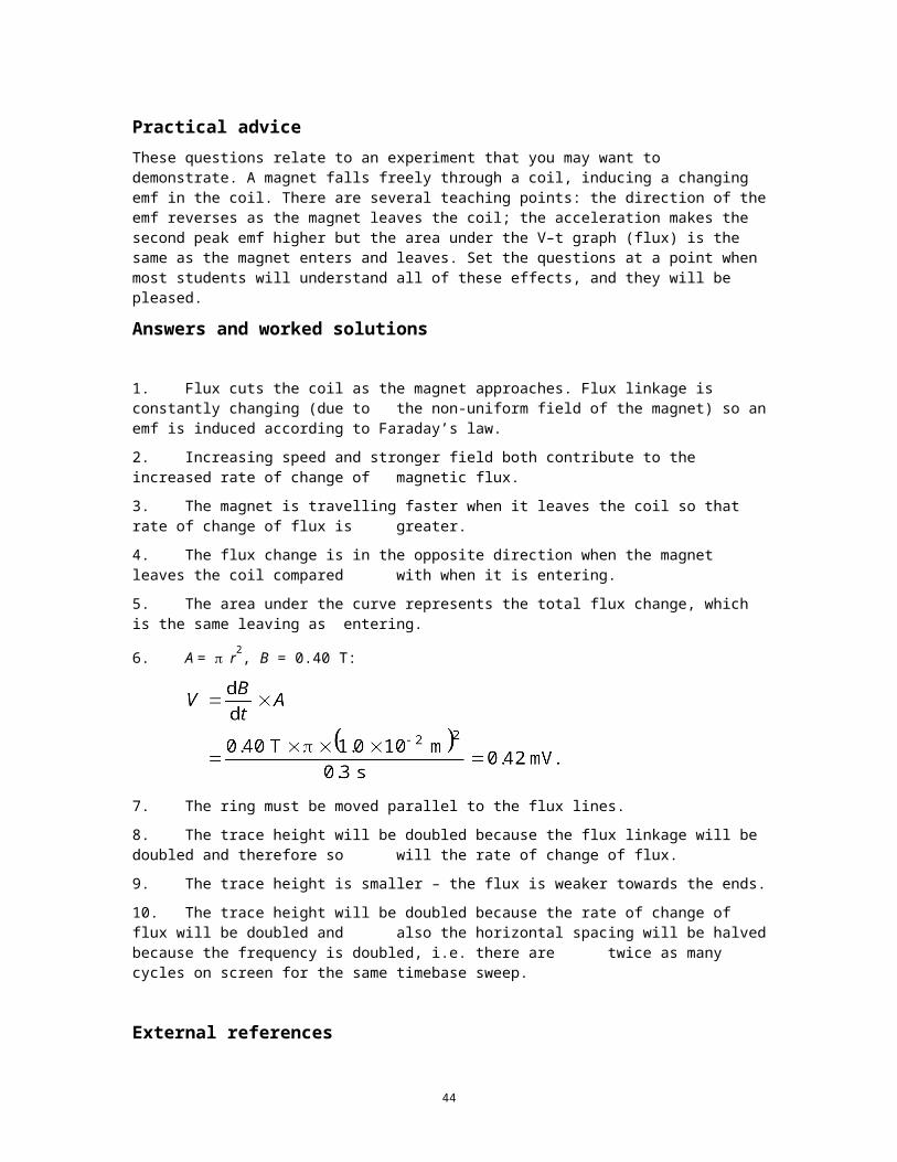
Practical adviceThese questions relate to an experiment that you may want to demonstrate. A magnet falls freely through a coil, inducing a changing emf in the coil. There are several teaching points: the direction of the emf reverses as the magnet leaves the coil; the acceleration makes the second peak emf higher but the area under the V–t graph (flux) is the same as the magnet enters and leaves. Set the questions at a point when most students will understand all of these effects, and they will be pleased.
Answers and worked solutions
1. Flux cuts the coil as the magnet approaches. Flux linkage is constantly changing (due to the non-uniform field of the magnet) so an emf is induced according to Faraday’s law.
2. Increasing speed and stronger field both contribute to the increased rate of change of magnetic flux.
3. The magnet is travelling faster when it leaves the coil so that rate of change of flux is greater.
4. The flux change is in the opposite direction when the magnet leaves the coil compared with when it is entering.
5. The area under the curve represents the total flux change, which is the same leaving as entering.
6. A = r2, B = 0.40 T:
7. The ring must be moved parallel to the flux lines.
8. The trace height will be doubled because the flux linkage will be doubled and therefore so will the rate of change of flux.
9. The trace height is smaller – the flux is weaker towards the ends.
10. The trace height will be doubled because the rate of change of flux will be doubled and also the horizontal spacing will be halved because the frequency is doubled, i.e. there are twice as many cycles on screen for the same timebase sweep.
External referencesThis activity is taken from Advancing Physics chapter 15, 80S
37
TAP 414-8: Emf in an airliner
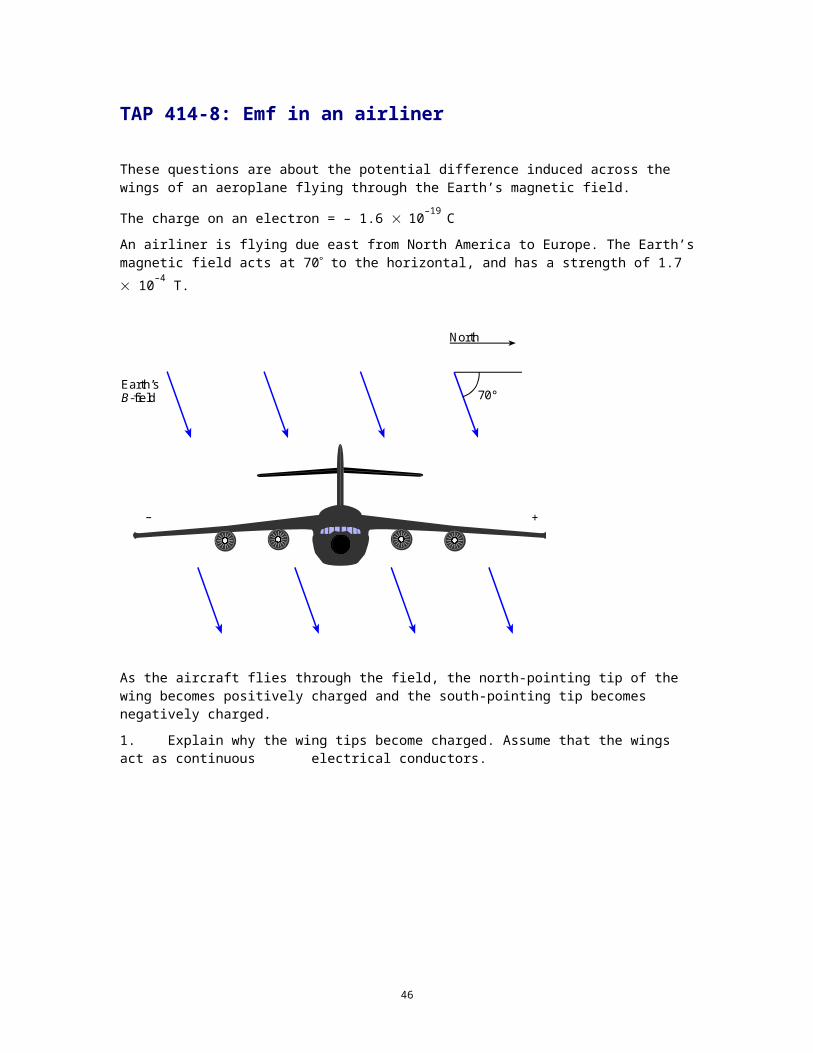
These questions are about the potential difference induced across the wings of an aeroplane flying through the Earth’s magnetic field.
The charge on an electron = – 1.6 10–19 C
An airliner is flying due east from North America to Europe. The Earth’s magnetic field acts at 70 to the horizontal, and has a strength of 1.7 10–4 T.
70°
North
Earth’sB-field
– +
As the aircraft flies through the field, the north-pointing tip of the wing becomes positively charged and the south-pointing tip becomes negatively charged.
1. Explain why the wing tips become charged. Assume that the wings act as continuous electrical conductors.
2. On the diagram above, show the direction of the component of the Earth’s magnetic field that is responsible for this horizontal movement of charge along the wings.
3. Calculate the magnitude of this component.
38
4. The aircraft’s speed is 270 m s–1. Calculate the horizontal component of the force exerted by the Earth’s magnetic field on an electron in the wing.
5. The wing span of the aircraft is 60 m. Calculate the potential difference induced between the tips of the wings.
The shape of the Earth’s magnetic field is as if there were a bar magnet at the centre of the Earth, aligned approximately along its rotational axis.
6. Explain why there is no significant voltage induced between the wing tips when the aircraft flies from west to east over the equator.
39
Practical adviceThese questions practise thinking about the emf in a conductor cutting magnetic flux.
Answers and worked solutions
1. The wings cut the flux lines of the Earth’s magnetic field, inducing an emf between the wing tips. An alternative answer is that the charges in the wings are moving through the Earth’s magnetic field and experience a force which redistributes the charge in the wings.
2. Vertically downward arrow to show the vertical component.
3. Vertical component = (1.7 10–4 T) cos 20 = 1.6 10–4 T.
4.
5.
6. At the equator the aircraft is flying parallel to the flux and cuts no (or very little) flux.
External referenceThis activity is taken from Advancing Physics chapter 15, 260S
40
Tap 414-9: Introducing eddy currents
Here you will look at changing magnetic fluxes inducing currents in circuit elements of magnetic and electric circuits. These currents generally dissipate energy, leading to inefficiency.
You will need:
3 mm thickness aluminium plate
scissors
thread
adhesive tape
retort stand, boss and clamp
large horseshoe magnet
large coil of insulated copper wire
copper tube
ceramic button magnet (Neodymium is best)
An overview You will be making some general observations about eddy currents. For each experiment, you should seek an explanation of what you see in terms of these induced currents opposing change.
Eddy current braking Set up this pendulum.
41
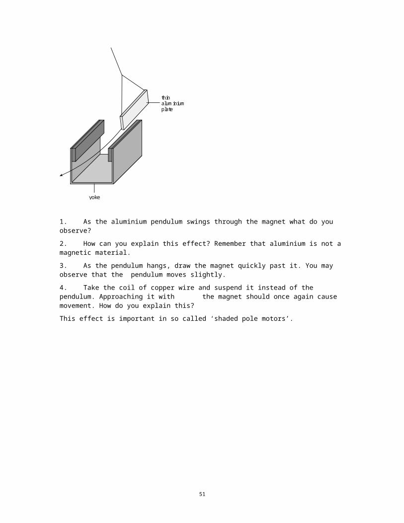
yoke
thinaluminiumplate
1. As the aluminium pendulum swings through the magnet what do you observe?
2. How can you explain this effect? Remember that aluminium is not a magnetic material.
3. As the pendulum hangs, draw the magnet quickly past it. You may observe that the pendulum moves slightly.
4. Take the coil of copper wire and suspend it instead of the pendulum. Approaching it with the magnet should once again cause movement. How do you explain this?
This effect is important in so called ‘shaded pole motors’.
42
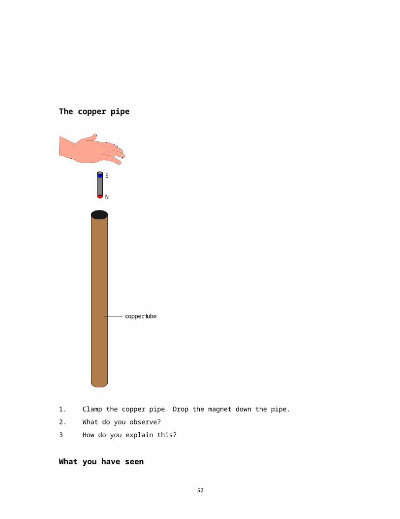
The copper pipe
copper tube
S
N
1. Clamp the copper pipe. Drop the magnet down the pipe.
2. What do you observe?
3 How do you explain this?
What you have seen
1. When a conductor moves in a magnetic flux it experiences a force which opposes the movement.
2. This force is due to the induction of eddy currents in the conductor.
3. The direction of the force demonstrates Lenz’s law.
43
Practical adviceAn extension of the pendulum experiment is to look at what happens if the aluminium has slits cut in it. Such a demonstration can lead to discussion of transformer lamination. It is best if the experiment is set up with magnets that cause the pendulum to stop after a few swings rather than straight away.
The copper pipe is an excellent experiment: simple, startling and memorable. It brings a smile to the face of most students. Having a piece of unmagnetised steel pipe of the same size is good for comparisons. If you have a very long piece of tube and somewhere to use it, the time taken to fall can be impressively huge. Further exploration of the origins of the retarding force can be done by hanging the pipe from a newton-meter whilst dropping the magnet down the tube.
If ‘magnetic viewing film’ is used you will see the magnet ‘move’ in the tube.
As a continuation, you could also compare it to a glass tube.
Alternative approachesYou may have a mounted aluminium disc; if you do not, it is well worth having one made. Such a disc can be used instead of the pendulum and makes the discussion of induction braking easier since the disc looks as if it is a wheel. This disc could also be used in induction motor experiments so it would represent a good investment. The jumping ring could be used here, but you may like to keep it until later to make an impact for induction motors.
Social and human contextRetarders (induction brakes) are fitted to most large vehicles. Students may have followed lorries that seem able to go at a suspiciously constant speed downhill. Regenerative braking in trains is important. Here’s an application perhaps worth mentioning alongside the copper pipe (although very tangential). If you place a large magnet outside you can hear the magnet fall and then suddenly stop. A medical application of fine suspensions, called liquid magnets, is to introduce them into the blood and use a magnet to stop them exactly where you wish a clot to form.
External referenceThis activity is taken from Advancing Physics chapter 15, 20E
44
TAP 414-10: Further eddy current demonstrations
Eddy CurrentsThis experiment is a very simple way of showing eddy current damping
You will need:
pile of small copper coins
copper cylinder
thread
retort stand
eclipse major magnet
What to do Suspend a copper cylinder from a thread so that it hangs between the poles of a large permanent magnet (flux density about 0.5 T). Twist the thread so that it oscillates about a vertical axis when released. The motion of the cylinder shows considerable damping because of the eddy currents set up within it. Now repeat the experiment using a pile of small copper or brass coins taped together.
You have seen The copper coins come to rest more slowly; the damping is much less because the gaps between the coins only allow much reduced eddy currents to flow in the stack
Electromagnetic brake
You will need:
large horseshoe magnet or a pair of Magnadur magnets on steel yoke
aluminium disc on horizontal axle
cotton
slotted masses and hanger
What to do Spin a non-magnetic metal disc between a pair of Magnadur magnets mounted vertically about a cm apart with opposite poles facing each other. The disc can be made to spin in a vertical plane by tying a piece of cotton to the axle of the disc and passing it over a pulley to a weight that is free to fall.
45
You have seen
Spinning a non-magnetic metal disc shows eddy current damping. As the weight falls it accelerates continually without the magnets but reaches a terminal velocity when they are in place.
Aluminium plate under a swinging magnet
You will need:
large horseshoe magnet
aluminium plate
retort stand
thread
What to do Suspend a bar magnet by a thread so that it hangs horizontally above an aluminium plate and start the magnet swinging
You have seen The magnet will soon come to rest because of the induced currents in the plate. This is a simple example of eddy current damping
Jumping ring and solid carbon dioxide
You will need:
demountable transformer
aluminium ring
mains coil and power
retort stand
solid carbon dioxide (optional)
46
The Jumping Ring
ac mains
SafetyThe coil used here must have been prepared for use on the mains. The insulation must be to mains standard and the 4mm connectors replaced with a proper mains connector.
What to do (a) The core of a demountable transformer is opened, a mains coil connected to the ac
mains and used as the primary and an aluminium ring as a secondary. The crosspiece is placed vertically on the arm round which the ring is slipped. Switch on the power.
The ring can be cooled by placing it in liquid nitrogen or solid carbon dioxide if the nitrogen is not available.
(b) Put the mains coil round the bottom of a retort stand using an aluminium ring to act as the secondary. As before you can cool the ring in solid carbon dioxide.
(c) An interesting extension to this experiment is to use a taller core round which to place the ring.
What you have seen (a) Switching on the current shoots the ring into the air
The repulsion between the magnetic fields produced by two electric currents is shown by this experiment with the aluminium ring.
Eddy currents induced in the ring form a magnetic field which is the same direction as that in the coil and so the ring is repelled
As a problem for the thinking students ask them what happens with a dc supply.
The ring can be cooled by placing it in liquid nitrogen or solid carbon dioxide if the nitrogen is not available.
(b) This increases the height risen by lowering the resistance of the ring and so increasing the size of the induced current in it. You might get some heating problems in the retort stand due to eddy currents set up within it so maybe it is better to use a section of a laminated core as the vertical part.
(c) The force on the ring acts for longer and so the ring rises higher when the current is switched on (A greater impulse Ft = mv).
47

External ReferenceThis activity is taken from Resourceful Physics
48
TAP 414-11: Eddy currents and Lenz’s law
These questions are all about induced currents. In some circumstances, these are called ‘eddy currents’.
Here is a diagram of the well-known ‘jumping ring’ experiment. If you have not yet seen it done ‘live’, ask your physics teacher to show it to you.
Al ring
solenoid
1. When the circuit is closed, the aluminium ring jumps and falls back down again. Explain why this happens.
2. What happens when the circuit is broken? Explain your answer.
3. The demonstration is a lot more effective if the coil has an iron core that extends some way above the end of the coil. Why is this?
4. It is possible to make the ring hover dramatically above the coil if an alternating current is passed through the coil. How can this happen?
49
5. Discuss the probable effect on the demonstration of using rings of different materials and dimensions.
Here is an aluminium vane that swings between the poles of a powerful magnet. When pulled back and released, it comes to rest very quickly. When slots are cut into the vane, it swings for a long time in the same magnetic field.
6. Explain the difference between the two results.
50
A solenoid is connected to a source of alternating current. Two pieces of iron, A and B, of identical dimensions are treated to look the same. When iron core A is inserted into the solenoid and the current switched on, the iron heats up rapidly and quickly reaches a temperature of 50C. When iron core B is inserted into the solenoid and the same current passed, there is no detectable heating effect.
a.c.
Iron core
7. Suggest and explain how the two pieces of iron differ.
51
Practical adviceThese are good practice questions. The initial ones concern what happens in the ‘jumping ring’ experiment, and would form a useful follow-up to that demonstration. Another question looks at eddy currents used for braking. A final question requires students to remember and understand why laminations are so helpful in magnetic cores.
Question 5 may be most suitable for a class discussion.
Answers and worked solutions
1. The current is switched on and produces a magnetic flux in the solenoid. Flux lines near the end of the solenoid cut the aluminium ring as the field grows. Change in flux linkage induces an emf in the ring and current flows. The direction of the induced current is such as to oppose the change inducing it (Lenz’s law) and the force on the ring due to current in the field acts to drive the ring out of the field, i.e. upwards. When the current, and therefore the flux, reaches a steady value, the induced current falls to zero and the ring falls.
2. The current is switched off and the flux collapses; induced current and the force are in the opposite direction.
3. Presence of iron increases the permeance and more flux is generated for the same current. Assuming that the flux changes at the same rate as without the iron, a greater emf will be produced. (Note: there is a potential problem here with self inductance – if it is very large, the current will collapse slowly.)
4. Alternating current generates an alternating force. Although the current direction changes, the force is always such as to push the ring out of the field – an effect which is counteracted by the weight of the ring. The ring hovers when these forces are (more or less) balanced.
5. Points for discussion include the effect of dimensions on resistance and therefore the size of the induced current; also different materials will have different resistivities. Changing dimensions will also affect the weight of the ring and therefore the balance between gravitational and electromagnetic forces.
6. The solid vane swings in the field, and the conductor cutting the flux lines induces eddy currents in the plane of the vane. Currents flow in such a direction as to minimise change – forces act so as to slow the motion of the vane, i.e. always act in the opposite direction to the motion. In the case of the slotted vane the presence of slots limits eddy currents and therefore the magnetic braking forces.
7. The bar which heats up is completely solid – the heating effect is due to induced currents in the core produced by the flux changing at 50 Hz. The bar remaining cool has been laminated, i.e. made up of thin strips of iron insulated from each other by a non-conducting coating.
External referenceThis activity is taken from Advancing Physics chapter 15, 120S
52