Tao Chen, Ye Yu, Dong Yu, Qiong He, Wei Hu, Tao Li ...
9
Research article Qingqing Cheng*, Juncheng Wang, Ling Ma, Zhixiong Shen, Jing Zhang, Xiaoying Zheng, Tao Chen, Ye Yu, Dong Yu, Qiong He, Wei Hu, Tao Li*, Songlin Zhuang and Lei Zhou* Achromatic terahertz Airy beam generation with dielectric metasurfaces https://doi.org/10.1515/nanoph-2020-0536 Received September 22, 2020; accepted November 29, 2020; published online December 14, 2020 Abstract: Airy beams exhibit intriguing properties such as nonspreading, self-bending, and self-healing and have attracted considerable recent interest because of their many potential applications in photonics, such as to beam focusing, light-sheet microscopy, and biomedical imaging. However, previous approaches to generate Airy beams using photonic structures have suffered from severe chro- matic problems arising from strong frequency dispersion of the scatterers. Here, we design and fabricate a metasurface composed of silicon posts for the frequency range 0.4–0.8 THz in transmission mode, and we experimentally demonstrate achromatic Airy beams exhibiting autofocusing properties. We further show numerically that a generated achromatic Airy-beam-based metalens ex- hibits self-healing properties that are immune to scattering by particles and that it also possesses a larger depth of focus than a traditional metalens. Our results pave the way to the realization of flat photonic devices for applications to noninvasive biomedical imaging and light-sheet micro- scopy, and we provide a numerical demonstration of a device protocol. Keywords: achromatism; Airy beam; metasurface; Pan- charatnam–Berry phase; transmission phase. 1 Introduction As a nontrivial solution of the paraxial equation of light [1], an Airy beam exhibits many remarkable features, such as self-bending (even in the absence of any external potential field), nonspreading, and self-healing after diffractions by obstacles [2–7]. Owing to these attractive properties, Airy beams have many potential applications in photonics, such as for particle manipulation [8], as light bullets [9, 10], for super-resolution imaging [11, 12], as autofocusing Airy (AFA) beams [13–15], and for light-sheet microscopy [16]. In 2007, Siviloglou and Christodoulides [17] proposed a truncated form of Airy beam and then realized it experimentally. Such a simplified version of an Airy beam, possessing finite en- ergy, preserves all the key features of an ideal Airy beam and has therefore attracted much attention recently. The conventional generation of Airy beams utilizes spatial light modulators (SLMs), which are bulky and lack fine spatial resolution [18–20]. The Airy beams generated in this way do not exhibit good qualities, and the bulky generation systems are unsuitable for practical applica- tions. Recently, plasmonic Airy beams [19, 21, 22] have been successfully generated on metallic surfaces on which are placed nanoscatterers that have been carefully designed to convert impinging light to surface plasmon waves with the desired amplitudes and phases. Although these devices are compact and exhibit improved spatial resolution, the *Corresponding authors: Qingqing Cheng, School of Optical- Electrical and Computer Engineering, University of Shanghai for Science and Technology, Shanghai 200093, China; Tao Li, National Laboratory of Solid State Microstructures, College of Engineering and Applied Sciences, Nanjing University, Nanjing 210093, China; and Lei Zhou, State Key Laboratory of Surface Physics, Key Laboratory of Micro and Nano Photonic Structures (Ministry of Education), Department of Physics, Fudan University, Shanghai 200438, China, E-mail: [email protected] (Q. Cheng), [email protected] (T. Li), [email protected] (L. Zhou). https://orcid.org/0000-0001-7386- 6081 (Q. Cheng) Juncheng Wang, Ling Ma, Jing Zhang, Tao Chen, Ye Yu, Dong Yu and Songlin Zhuang, School of Optical-Electrical and Computer Engineering, University of Shanghai for Science and Technology, Shanghai 200093, China, E-mail: [email protected] (J. Wang), [email protected] (L. Ma), [email protected] (J. Zhang), [email protected] (T. Chen), [email protected] (Y. Yu), [email protected] (D. Yu), [email protected] (S. Zhuang) Zhixiong Shen and Wei Hu, Key Laboratory of Intelligent Optical Sensing and Manipulation and College of Engineering and Applied Sciences, Nanjing University, Nanjing 210093, China, E-mail: [email protected] (Z. Shen), [email protected] (W. Hu) Xiaoying Zheng and Qiong He, State Key Laboratory of Surface Physics, Key Laboratory of Micro and Nano Photonic Structures (Ministry of Education), Department of Physics, Fudan University, Shanghai 200438, China, E-mail: [email protected] (X. Zheng), [email protected] (Q. He). https://orcid.org/0000- 0002-4966-0873 (Q. He) Nanophotonics 2021; 10(3): 1123–1131 Open Access. © 2020 Qingqing Cheng et al., published by De Gruyter. This work is licensed under the Creative Commons Attribution 4.0 International License.
Transcript of Tao Chen, Ye Yu, Dong Yu, Qiong He, Wei Hu, Tao Li ...

Research article
Qingqing Cheng*, Juncheng Wang, Ling Ma, Zhixiong Shen, Jing Zhang, Xiaoying Zheng,Tao Chen, Ye Yu, Dong Yu, Qiong He, Wei Hu, Tao Li*, Songlin Zhuang and Lei Zhou*
Achromatic terahertz Airy beam generation withdielectric metasurfaces
https://doi.org/10.1515/nanoph-2020-0536Received September 22, 2020; accepted November 29, 2020;published online December 14, 2020
Abstract: Airy beams exhibit intriguing properties such asnonspreading, self-bending, and self-healing and haveattracted considerable recent interest because of theirmany potential applications in photonics, such as to beamfocusing, light-sheet microscopy, and biomedical imaging.However, previous approaches to generate Airy beamsusing photonic structures have suffered from severe chro-matic problems arising from strong frequency dispersion ofthe scatterers. Here, we design and fabricate a metasurfacecomposed of silicon posts for the frequency range0.4–0.8 THz in transmission mode, and we experimentallydemonstrate achromatic Airy beams exhibiting
autofocusing properties. We further show numerically thata generated achromatic Airy-beam-based metalens ex-hibits self-healing properties that are immune to scatteringby particles and that it also possesses a larger depth offocus than a traditional metalens. Our results pave the wayto the realization of flat photonic devices for applications tononinvasive biomedical imaging and light-sheet micro-scopy, and we provide a numerical demonstration of adevice protocol.
Keywords: achromatism; Airy beam; metasurface; Pan-charatnam–Berry phase; transmission phase.
1 Introduction
As a nontrivial solution of the paraxial equation of light [1],an Airy beam exhibits many remarkable features, such asself-bending (even in the absence of any external potentialfield), nonspreading, and self-healing after diffractions byobstacles [2–7]. Owing to these attractive properties, Airybeams have many potential applications in photonics, suchas for particle manipulation [8], as light bullets [9, 10], forsuper-resolution imaging [11, 12], as autofocusingAiry (AFA)beams [13–15], and for light-sheet microscopy [16]. In 2007,Siviloglou and Christodoulides [17] proposed a truncatedform of Airy beam and then realized it experimentally. Sucha simplified version of an Airy beam, possessing finite en-ergy, preserves all the key features of an ideal Airy beamandhas therefore attracted much attention recently.
The conventional generation of Airy beams utilizesspatial light modulators (SLMs), which are bulky and lackfine spatial resolution [18–20]. TheAiry beams generated inthis way do not exhibit good qualities, and the bulkygeneration systems are unsuitable for practical applica-tions. Recently, plasmonicAiry beams [19, 21, 22] have beensuccessfully generated on metallic surfaces on which areplaced nanoscatterers that have been carefully designed toconvert impinging light to surface plasmon waves with thedesired amplitudes andphases. Although these devices arecompact and exhibit improved spatial resolution, the
*Corresponding authors: Qingqing Cheng, School of Optical-Electrical and Computer Engineering, University of Shanghai forScience and Technology, Shanghai 200093, China; Tao Li, NationalLaboratory of Solid State Microstructures, College of Engineering andApplied Sciences, Nanjing University, Nanjing 210093, China; and LeiZhou, State Key Laboratory of Surface Physics, Key Laboratory ofMicro and Nano Photonic Structures (Ministry of Education),Department of Physics, Fudan University, Shanghai 200438, China,E-mail: [email protected] (Q. Cheng), [email protected] (T. Li),[email protected] (L. Zhou). https://orcid.org/0000-0001-7386-6081 (Q. Cheng)Juncheng Wang, Ling Ma, Jing Zhang, Tao Chen, Ye Yu, Dong Yuand Songlin Zhuang, School of Optical-Electrical and ComputerEngineering, University of Shanghai for Science and Technology,Shanghai 200093, China, E-mail: [email protected] (J. Wang),[email protected] (L. Ma), [email protected] (J. Zhang),[email protected] (T. Chen), [email protected] (Y. Yu),[email protected] (D. Yu), [email protected] (S. Zhuang)Zhixiong Shen and Wei Hu, Key Laboratory of Intelligent OpticalSensing and Manipulation and College of Engineering and AppliedSciences, Nanjing University, Nanjing 210093, China,E-mail: [email protected] (Z. Shen), [email protected] (W. Hu)Xiaoying Zheng and Qiong He, State Key Laboratory of SurfacePhysics, Key Laboratory of Micro and Nano Photonic Structures(Ministry of Education), Department of Physics, Fudan University,Shanghai 200438, China, E-mail: [email protected](X. Zheng), [email protected] (Q. He). https://orcid.org/0000-0002-4966-0873 (Q. He)
Nanophotonics 2021; 10(3): 1123–1131
Open Access. © 2020 Qingqing Cheng et al., published by De Gruyter. This work is licensed under the Creative Commons Attribution 4.0International License.

generated Airy beams can flow only on certain planes, andthe working efficiencies are quite low owing to the intrinsiclosses and nonideal performances of the metallic nano-scatterers that are used. For practical applications,it is highly desirable to have ultracompact and broadbanddevices that can efficiently generateAirybeams in free space.
Metasurfaces, ultrathin metamaterials consisting ofsubwavelength microstructures (e.g., meta-atoms) withtailored optical properties, offer a fascinating platform onwhich to realize planar photonic devices with desiredfunctionalities [23–37]. In the past few years, Airy beamshave been successfully generated by carefully designedmetadevices constructed from meta-atoms of differenttypes (metallic or dielectric resonators) that can scatterelectromagnetic waves with desired amplitudes and pha-ses [20,38–40]. These ultrathin devices can generate Airybeams in free space with relatively high efficiencies.However, since the phase responses of the adopted reso-natingmeta-atoms typically exhibit Lorentz-like frequencydispersion, such metadevices can usually work only at aspecific single frequency at which the system preciselyexhibits the phase/amplitude distributions required by theanalytical formula. Despite several attempts (using, forexample, geometric-phase metasurfaces [38, 39, 41, 42] ordouble-stacked metasurfaces [40]), the constructed meta-devices still suffer from chromatic issues [3,43–48], whichhinders their practical application.
In this paper, we experimentally realize achromaticAiry beams in the terahertz (THz) regime with a carefullydesigned dielectric metasurface. Our metadevice consistsof a set of silicon posts with different sizes and orientationangles determined by the requirement to generate thedesired phase profile for achromatic Airy beams within abroad frequency band of 0.4–0.8 THz.Wedemonstrate thatthe generated achromatic Airy beams exhibit self-healingproperties. In addition, an Airy-beam-based metalens isconstructed by combining two such achromatic Airy beamsand possesses a large depth of focus and robustnessagainst scatterers. Our results stimulate us to propose adevice protocol for Airy-beam-based metalens microscopybased on the proposed metasurface.
2 Results and discussions
2.1 Design principle for generation of THzachromatic Airy beams
Rather than using a fixed spatial wavefront to generate achromatic Airy beam, here we exploit a wavelength-
dependent spatial phase based on a silicon metasurfaceto generate an achromatic Airy beam with the same tra-jectory. A schematic of the achromatic Airy beamgeneratoris shown in Figure 1(a). The incident THz wave impingesvertically on the metasurface device and the transmittedTHz wave follows the trajectory along the white dash linef (z). To realize the achromatic Airy beam, herewe study thetruncated Airy beam to acquire the wavelength-dependentspatial phase of the achromatic Airy beam. The Airy beamis generated by an initial field distribution in the meta-surface plane at z = 0, given by ψ(x, z � 0) � Ai(x) . Here,we employ the semiclassical approximation to analyze theAiry function. The standard asymptotic forms show thatψ(x, z � 0) is exponentially small for x > 0, and hence negli-gible, and is oscillatory for x < 0, the precise expression being
ψ(x, z �0)≈(−π2x)−1/4sin[23(−x)3/2+ π
4]� A+eikϕ+ +A−eikϕ− ),
where ϕ± �∓23(−x)3/2+π/4 and A± �±(i/2)(−π2x)−1/4 are the
initial phases and amplitude functions. The initial phases ϕ+and ϕ− give rise to rays that propagate along the +x andopposite −x directions. Specifically, the ray species ϕ+emerges sideways, converging toa caustic along the trajectory
f(z) �(az2)/4,where the variablea is equal to 1/(k2x30), and kand x0 are the wavenumber and an arbitrary transverse scale.The details of the parabolic trajectory are derived in Note S1 inthe Supplementary material. The geometric constructionderiving the phase profile is illustrated in Figure 1(b). Theparabolic trajectory is indicatedby theblackdashcurve f (z) asshown, and we obtain the corresponding spatial phasefunction φ(x) at the metasurface plane with z = 0 that willgenerate the curve as a caustic. The caustic is constructed astheenvelope toa familyof raysϕ+ such that eachpointxat theplane z=0canbe functionally related toapoint on the caustic
via a tangent of slopeθ,where tanθ � f ′(z) � df(z)/dz. Sincethe tangent can be parameterized in terms of x using
f ′(z) � [f(z) −x]/z, we can determine the desired phasedistributions by integrating the phase derivative condition:
dφ(x)dx
� ksinθ � kf ′(z)���������1 + [f ′(z)]2
√ . (1)
When the analysis in the preceding discussion issimplified in the paraxial approximation, we obtain thefollowing wavelength-dependent phase profile:
φ(x, f ) � −43a1/2π(−x)3/2 ⋅ f
c+ φshift(f ) (2)
where the valueofφshift(f ) represents an integration constantat the frequence of f. To realize an achromatic Airy beamwithin f ∈ [ fmin � 0.4 THz, fmax � 0.8 THz] in Figure 1(c),
1124 Q. Cheng et al.: Achromatic terahertz Airy beam generation

we need to design ametasurface exhibiting the phase profileφ(x, f ), as shown in Eq. 2, for every frequency within theband [fmin, fmax].
We now illustrate how to design such a metasurfaceexhibiting the desired phase profile. With φshift(f ) termdropped for the moment, we decompose the remaining partof phase profile φ(x, f) into two parts, namely a basic phaseprofile φ1(x, f ) representing the phase profile required bythe device at fmin and φ2(x, f ) the phase difference at otherfrequencies. Straightforward calculations yield that:
φ1(x, f ) � −4πa1/2
3cx3/2 ⋅ fmin , (3)
and
φ2(x, f ) � −4πa1/2
3cx3/2 ⋅ (f − fmin) . (4)
Now our task is to design a series of meta-atoms, whichnot only yield the required phases required by Eq. (3) at thefrequency fmin, but also exhibit the different frequency dis-persions as dictated by Eq. (4). However, φ2(x, f ) exhibitsnegative slopesagainst frequencyat everypointx,whichcannot be realized by any resonating structures exhibitingnormal frequency dispersions (i.e., transmission phasesare increasing functions of frequency). Fortunately, there isan additional term φshift(f ) in Eq. (2), which can befreely chosen to solve this issue. Specifically, setφshift(f ) � α ⋅ (f − fmin), we find that:
φ(x, f ) � φ1 + φ2 + φshift
� −4πa1/2
3cx3/2 ⋅ fmin + [− 4πa1/2
3cx3/2
+ α](f − fmin) . (5)
Choosing an appropriate α value, we can make the
term [− 4πa1/23c x3/2 + α] taking positive values at every posi-
tion x, so that such frequency-dependent phase profilescan be realizable using resonating meta-atoms.
We proceed to search a series of meta-atoms exhib-iting the desired phases (Eq. (3)) at frequency fmin andfrequency-variation slopes as required by Eq. (5). Thebuilding structures of the silicon metasurface are pre-sented in Figure 2(a) and (b), consisting of solid and in-verse rectangular structures on a silicon substrate. Tofulfill the complex requirements on the phase responses,we design the metastructures based on a combination oftwo mechanisms, namely, the resonance mechanismyielding a frequency-dependent transmission phase andthe Pancharatnam-Berry (PB) one yielding a frequency-independent phase. Since the PB mechanism is adopted,we assume the incident THz wave to exhibit RCP, andemploy finite-difference time-domain (FDTD) simulationsto determine the width w and length l of our meta-structures (with fixed lattice period p and etching depth t)based on two criterions: 1) transmission phases exhibit
Figure 1: Schematic and phase profile of an achromatic Airy beam.(a) Schematic of the experimental generation of terahertz (THz) achromatic Airy beams by a silicon metasurface. The transmitted left circularpolarization (LCP) THz intensities in the x–z plane fit the parabolic trajectory f (z) for the right circular polarization (RCP) incident light. (b) Todetermine the phase distribution φ(x, f ) of the metasurface under design, we draw an auxiliary line (black solid line) tangent to the parabolicasymptotical trajectory f (z) of the desired Airy beam (black dash line) at an arbitrary point, which intersects with x axis exhibiting an angle θ.With θ(x) function obtained by repeating such a process, we then obtain φ(x, f ) based on Eq. (1). (c) Phase profile of an achromatic Airy beamwithin the frequency range f ∈ [fmin, fmax], where fmin � 0.4 THz, fmax � 0.8 THz, φshift � 820∘ at 0.8 THz, and the arbitrary transverse scalex0 = 650 µm in our design.
Q. Cheng et al.: Achromatic terahertz Airy beam generation 1125
linear dependences on frequencywith desired slopes; and2) they possess relative high conversion efficiencies toLCP within the frequency band of interest. The section ofmethod provides more simulation details. Finally, wecarefully select 32 different structural parameters con-taining solid and inverse rectangular structures in Ta-ble S1 and present the individual phase responses andconversion efficiencies in Figure S1.To directly present thecoversion efficiencies, we provide an efficiency map (asshown in Figure S2) of the selected meta-atoms withrespect to different frequencies. Here as an example,Figure 2(c) presents the simulated phase differences of thesolid structure (sequence number 15, 580°) and the in-verse structure (sequence number 27, 725°) with a same
etching depth t = 350 μm, showing the linear phaseresponse as a function of f (or 1/λ). Note that the inversestructures in Table S1 have a wider phase response thanthe solid structures in Table S1 and can compensate for alarger phase difference, so that the positions of the inversestructures are close to x = 0 and those of the solid struc-tures are close to the left edge of the sample, as shown inFigure 1(a).
Before closing this section, we emphasize that onlythe LCP component of the transmitted wave can acquirethe PB phases under RCP incidence [49, 50], so that onlythis wave component can generate the desired achro-matic Airy beam. Moreover, the metadevice thus con-structed does not work for linear-polarization incidenceunder which the meta-atoms do not generate any PBphase.
2.2 Numerical calculation of THz achromaticAiry beams
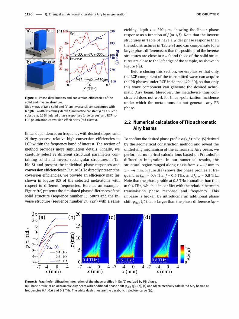
To confirm thedesiredphase profileφ (x, f ) in Eq. (5) derivedby the geometrical construction method and reveal theunderlying mechanism of the achromatic Airy beam, weperformed numerical calculations based on Fraunhoferdiffraction integration. In our numerical results, thestructural region ranged along x axis from x = −7 mm tox = +4 mm. Figure 3(a) shows the phase profiles at fre-quencies fmin = 0.4 THz, f = 0.6 THz, and fmax = 0.8 THz.Note that the phase profile at 0.8 THz is smaller than thatat 0.4 THz, which is in conflict with the relation betweentransmission phase response and frequency. Thisimpasse is broken by introducing an additional phaseshift φshift(f ) that is larger than the phase difference Δφ �
Figure 2: Phase distributions and conversion efficiencies of thesolid and inverse structure.Side views of (a) a solid and (b) an inverse silicon structures withlength l, width w, etching depth t, and lattice constant p on a siliconsubstrate. (c) Simulated phase responses (blue curves) and RCP-to-LCP polarization conversion efficiencies (red curves).
Figure 3: Fraunhofer diffraction integration of the phase profiles in Eq.(2) realized by PB phase.(a) Phase profile of an achromatic Airy beam with additional phase shift φshift(f ). (b), (c) and (d) Numerically calculated Airy beams atfrequencies 0.4, 0.6 and 0.8 THz. The white dash lines are the parabolic trajectory curve f (z).
1126 Q. Cheng et al.: Achromatic terahertz Airy beam generation

φ0.4THz − φ0.8THz � 1350∘ at the position x = −7 mm. Tocompensate for the large phase difference, the buildingstructures are no longer subwavelength. In this case, weresort only to the geometric phases of three differentangles of rotation with respect to the laboratory coordi-nate system to match the phase profiles of Airy beamswith different frequencies at 0.4, 0.6, and 0.8 THz.Table S2 in the Supplementary material shows thestructural parameters and the rotated angle distributions.Subsequently, we performed a numerical calculation
based on the initial field F {eikφ(x)}, in which all meta-surfaces in the array with period 70 μm were consideredas subsources radiating cylindrical surface waves withdesigned initial phase profiles. Figure 3(b–d) shows thenumerically calculated Airy beams and Figure S3(a–c) inthe Supplementary material show the FDTD simulatedbeams at frequencies 0.4, 0.6, and 0.8 THz. We find thatthe trajectories of the Airy beams are in good agreementwith the parabolic curve f (z), although they are bothimperfect owing to the limited number of metasurfaceelements and the nonideal phase profiles.
2.3 Experimental setup and fabricatedsamples
To validate the above theoretical analysis, we designed asiliconmetasurface device for generating a broadband THzachromatic Airy beam. However, the theoretical design ofachromatic Airy beams requires a phase compensation of1350°, which cannot be compensated owing to the largeaspect ratio in experimental fabrication. Therefore, wereduced the sample size, which ranges along the x-axisfrom −3.2 to 4 mm. In our design, we chose the additionalphase shift φshift(f ) to be 820° at 0.8 THz. To encode thephase profiles of the achromatic Airy beam within the fre-quency band, we placed the 32 selected structures at xcoordinates with approximately equal phase differences,as shown in Figure S4, in the Supplementary material. Thestarting points of each vertical line is the initial phaseφ0 at0.4 THz, and the height of each vertical line is the phasecoverage (or phase difference). The unresolved problem isto realize the phase profile at 0.4 THz. Here, the phaseprofile is taken as the basic phase φ1(x, f), determining theparabolic trajectory of the achromatic Airy beamwithin thefrequency range. The basic phaseφ1(x, f) is related solely tofmin and is independent of the working frequency f. The PBphase, which is independent of the transmission phase, isused to acquire the phase profile at 0.4 THz. To obtain thecorrect basic phase φ1(x, f), the spatial rotation angle θ of
each structural unit is taken as θ � (φ1 − φ0)/2 (for furtherdetails, see Table S3 in the Supplementary material)
To verify the reliability of our designed metasurfacedevices,we fabricated samples to generate achromatic Airybeams and explore the corresponding characteristics usingTHz near-field scanning microscopy (NFSM), as shown inFigure 4(a). The polarizer controls the polarization of thelight output by the fiber laser, which is focused by the lensand reflected by themirror, and finally illuminates the lighton the probe. In the real system shown in Figure S5 in theSupplementary material, the collimated THz waves radi-ating from a 100 fs (λ=780 nm) laser-pulse-pumpedphotoconductive antenna emitter are modulated with anappropriately polarized state. A commercial THz near-fieldprobe is positioned 2 mm away from the sample to detectthe Ex of the transmitted LCP light, with the RCP lightilluminating the metasurface device. The sample is fabri-cated on a silicon wafer by conventional lithographytogether with deep reactive ion etching. Further details ofsample fabrication are given inmethods. Figure 4(b) showsan optical microscope image of the whole of the fabricated
Figure 4: Experimental setup of the terahertz (THz) near-fieldscanning microscopy (NFSM) and sample images.(a) Schematic of THz NFSM. (b) Optical image of the whole sample.(c) Partial enlargement on the right side (red desh box) of the inversestructures. (d) Partial enlargement on the left side (red box) of thesolid structures.
Q. Cheng et al.: Achromatic terahertz Airy beam generation 1127

sample. Figure 4(c) and (d) shows partially enlargedscanning electron microscope (SEM) images of the inverseand solid structures, respectively. Note that the inversestructures with a larger phase compensation are locatedtoward the right of the metasurface device, while the solidstructures with a smaller phase compensation are locatedtoward the left side.
2.4 Experimental detection of THzachromatic Airy beams
Figure 5(a)–(c) shows the normalized abs(Ex) distributionsof the transmitted LCP light obtained from the THzNFSM atthe three frequencies. Note that there are no data for thefirst 2 mm in the experimental results because of a safetydistance imposed during the experiment to prevent colli-sions. In these figures, the normalized abs(Ex) distributionsshow a goodmatch with the parabolic trajectory (the whitedash line) at 0.4 THz. To verify the experimental results,Figure 5(d)–(f) presents the normalized intensity distribu-tions Ex simulated by FDTD at frequencies 0.4, 0.6, and0.8 THz, respectively. Furthermore, in Figure S6 in theSupplementary material, we present the results ofFraunhofer diffraction integration at more frequencies, theresults of simulation, and experimental data, all of whichverify the achromatism of the Airy beams. For a moreintuitive comparison between the simulation results andexperimental data, we obtain the lateral offsets x of themaximum normalized intensity (with error bars corre-sponding to 95% of the maximum normalized intensity) at
different propagation distances z and compare them withthe numerical deflection. Figure 5(g)–(i) shows the resultsof this comparison at the three frequencies, and it can beseen that there is good agreement. In the simulation, wecalculated theworking efficiency of the device, as shown inFigure S7 in the Supplementary material. The working ef-ficiency ranges from 20 to 60% and is higher at frequenciesnear 0.6 THz. Furthermore, we present the simulation re-sults for the self-healing properties of the achromatic Airybeam in the case of scattering by silicon particles inFigure S8 in the Supplementary material.
2.5 THz achromatic Airy-beam-basedmetalens
Airy-beam-based metalenses have many advantages fordetection, such as large depth of focus (DOF) and self-healing properties, and so herewe design ametalens basedon autofocusing achromatic Airy beams. To realize this, theachromatic Airy-beam-based metalens, a metasurface de-vice composed of two symmetrical structures is designed togenerate two counter-propagating achromatic Airy beams.Figure S9 in the Supplementarymaterial shows optical andSEM images of the metasurface device. To highlight therobustness of theAiry-beam-basedmetalens, an aluminumfoil cover is placed over a 1 mm region (ranging along thex-axis from x = −0.5 mm to x = +0.5 mm) around the centerof the experimental sample. Figure 6(d)–(f) shows thenormalized abs (Ex) distributions of the metalens at
Figure 5: Achromatic Airy beam experiments.(a)–(c) Experimental results on near-field detections at the three frequencies, showing that the intensity distributions of the left circularpolarization (LCP) field transmitted through the metasurface devices match well with the white dash line indicating the parabolic trajectory.(d)–(f) Simulation results at the three frequencies. (g)–(i) Comparison of experiment, simulation, and theoretical deflections, where the errorbars correspond to 95% of the maximum normalized intensity.
1128 Q. Cheng et al.: Achromatic terahertz Airy beam generation

frequencies 0.4, 0.6 and 0.8 THz, respectively. Experi-mental results are presented on the left and FDTD resultson the right. Experimental results at other frequencies areshown in Figure S10 in the Supplementary material. Inparticular, it should be noted that there is less energy inthe region covered by aluminum foil, which is quitedifferent fromwhat occurswith a traditionalmetalens. Theintensity distributions in the vertical direction at the centerof the two cases can be found in Figure S11 in the Sup-plementary material. A comparison shows that the Airy-beam-based metalens has the advantage of a larger DOFand detection with a high signal-to-noise ratio. Interest-ingly, the starting points of the autofocusing effect fit wellwith the intersection of the parabolic trajectory. When twocounter-propagating achromatic Airy beams begin tointersect, constructive interference occurs, and the tra-jectory curves coincide with the lower edge of thenormalized intensity distributions of the focal spots.Furthermore, because the full width at half maximum(FWHM) of the focal spots is themain indicator to evaluatethe performance of Airy-beam-based metalenses, wecompared the experimental and theoretical distributionsat a focal length f = 10 mm andmeasured the FWHM at thethree frequencies, as shown in Figure 6(a)–(c). The FWHMis 0.84 mm at 0.4 THz (λ = 0.75 mm), 0.52 mm at 0.6 THz(λ = 0.5 mm), and 0.38 mm at 0.8 THz (λ = 0.375 mm). The
experimental results agree well with those of the simula-tions, and the FWHMs are approximately equal to thewavelength of incidence of the THz wave. The self-healingproperty is typically verified by placing an obstacle on thetravel path of the parabolic trajectory. The trajectory re-covers quickly if two silicon obstacles of diameter 400 μmare located at (x, z) = (−0.8 mm, 6 mm) and (0.8 mm,6 mm), indicating a rather robust self-healing property ofthe generated Airy-beam-based metalens. The self-bending, diffraction-free, and self-healing achromaticproperties are illustrated in Figure S12 in the Supplemen-tary material.
3 Conclusion
We have experimentally demonstrated achromatic Airybeams in the THz regime using carefully designed siliconmetasurface devices. Furthermore, we have shownnumerically that a metalens based on an achromatic Airybeamhas the advantages of a larger DOF and a self-healingproperty comparedwith a traditional achromaticmetalens.The achromatic Airy beam developed in this paper hasimportant potential applications to light-sheetmicroscopy,self-healing metalens bio-imaging, and high signal-to-noise ratio detection.
Figure 6: Achromatic Airy beam-based metalens.(a)–(c) Comparison of simulated and experimental results for the intensity distributions at the focal length. The full width at half maximum(FWHMs) of the intensity distribution are 0.84 mm at 0.4 THz, 0.52 mm at 0.6 THz, and 0.38 mm at 0.8 THz. (d)–(f) Demonstration of thegeneration of two counter-propagating achromatic Airy beams in experiments and simulations. The focal length f = 10 mm.
Q. Cheng et al.: Achromatic terahertz Airy beam generation 1129
4 Methods
4.1 Simulation details
FDTD was used to find and simulate the structural units and thetransmission Ex field of the metasurface devices. In the simulation ofthe unit, the mesh grid size was set to 10 nm. In the simulation of thewhole metasurface device, the grid size was set to 1 μm
4.2 Sample fabrication
All the siliconmetasurface deviceswere fabricatedusing conventionallithography together with deep reactive ion etching. The refractiveindex n of silicon is 3.45 and its resistance R is higher than 104 Ω cm.First, a 2-μm-thick silica layer was grown on a 500-μm-thick double-side-polished high-resistivity silicon wafer. Next, by conventionalphotolithography, the left photoresist and the silica became a doublelayer of protection above the silicon posts. Conventional deep reactiveion etching was then employed to make silicon posts of thicknesst = 350 μm. Finally, the remaining photoresist and the remaining silicawere cleaned off separately.
4.3 Experimental characterization
THz near-field scanning microscopy was employed in the experimentaltests owing to its high scanning speed and high resolution. Here, onlythe x-polarized electric field Ex component was measured with RCPillumination. The electric field was detected at 0.2 mm intervalsfrom −3.2 to 4 mm in both the x and z directions. Note that we reserved2mmtoavoid collisionsbetween theprobeand themetasurfacedevices.
Author contributions: Q.C., J.W. and L.M. contributedequally to this work. J.C., L.M., Z.S., J.Z., and X.Z. carriedout simulations, fabricated the samples and conductedpart of the measurements; J.W., T.C., Y.Y., and D.Y. did thetheoretical calculations and designed the samples; J.W.and Z.S. built the experimental setup and conducted part ofmeasurements; Q.H. andW.H. provided technical supportsfor simulations and data analyses. Q.C., S.Z. and L.Z.organized the project, designed experiments and analyzedthe results. All the authors contributed to the preparationof the manuscript, and have accepted responsibility for theentire content of this submitted manuscript and approvedsubmission.Research funding: This workwas funded byNational NaturalScienceFoundationofChina (No. 11874266,No. 11604208,No.11734007, No. 91850101, No. 11674068, No. 11874118),National Key Research and Development Program of China(No. 2017YFA0303504andNo. 2017YFA0700201), ChenguangProgram (17CG49), Natural Science Foundation of Shanghai(No.20JC1414601 and No.18ZR1403400).Conflict of interest statement: The authors declare noconflicts of interest regarding this article.
References
[1] M. V. Berry and N. L. Balazs, “Nonspreading wave packets.Nonspreading wave packets,” Am. J. Phys., vol. 47, p. 264, 1979.
[2] M. Henstridge, C. Pfeiffer, D. Wang, et al., “Accelerating lightwith metasurfaces,” Optica, vol. 5, p. 678, 2018.
[3] G. A. Siviloglou, J. Broky, A. Dogariu, and D. N. Christodoulides,“Observation of accelerating airy beams,” Phys. Rev. Lett.,vol. 99, p. 213901, 2007.
[4] Y. Lumer, Y. Liang, R. Schley, et al., “Incoherent self-acceleratingbeams,” Optica, vol. 2, p. 886, 2015.
[5] A. Salandrino and D. N. Christodoulides, “Airy plasmon: anondiffracting surface wave,” Opt. Lett., vol. 35, p. 2082, 2010.
[6] J. Broky, G. A. Siviloglou, A. Dogariu, and D. N. Christodoulides,“Self-healing properties of optical airy beams,” Opt. Express,vol. 16, p. 12880, 2008.
[7] N. K. Efremidis, Z. Chen, M. Segev, and D. N. Christodoulides,“Airy beams and accelerating waves: An overview of recentadvances,” Optica, vol. 6, p. 686, 2019.
[8] J. Baumgartl, M. Mazilu, and K. Dholakia, “Optically mediatedparticle clearing using airy wavepackets,” Nat. Photonics, vol. 2,p. 675, 2008.
[9] A. Chong, W. H. Renninger, and D. N. Christodoulides, “Airy–bessel wave packets as versatile linear light bullets,” Nat.Photonics, vol. 4, p. 103, 2010.
[10] D. Abdollahpour, S. Suntsov, D. G. Papazoglou, andS. Tzortzakis, “Spatiotemporal airy light bullets in the linear andnonlinear regimes,” Phys. Rev. Lett., vol. 105, p. 253901, 2010.
[11] S. Jia, J. C. Vaughan, and X. Zhuang, “Isotropic three-dimensional super-resolution imaging with a self-bending pointspread function,” Nat. Photonics, vol. 8, p. 302, 2014.
[12] S. Jia, “Super-resolution imaging with airy beams,” in Laser Sci,vol. 180, p. 2520, 2015.
[13] Q. Fan, D. Wang, P. Huo, Z. Zhang, Y. Liang, and T. Xu,“Autofocusing airy beams generated by all-dielectric metasurfacefor visible light,” Opt. Express, vol. 25, p. 9285, 2017.
[14] P. Zhang, J. Prakash, Z. Zhang, et al., “Trapping and guidingmicroparticles with morphing autofocusing airy beams,” Opt.Lett., vol. 36, p. 2883, 2011.
[15] M. Manousidaki, D. G. Papazoglou,M. Farsari, and S. Tzortzakis,“Abruptly autofocusing beams enable advanced multiscalephoto-polymerization,” Optica, vol. 3, p. 525, 2016.
[16] T. Vettenburg, H. I. Dalgarno, J. Nylk, et al., “Light-sheetmicroscopy using an airy beam,” Nat. Methods, vol. 11, p. 541,2014.
[17] G. A. Siviloglou and D. N. Christodoulides, “Accelerating finiteenergy airy beams,” Opt. Lett., vol. 32, p. 979, 2007.
[18] T. Latychevskaia, D. Schachtler, and H.-W. Fink, “Creating airybeams employing a transmissive spatial light modulator,” Appl.Opt., vol. 55, p. 6095, 2016.
[19] P. Zhang, S. Wang, Y. Liu, et al., “Plasmonic airy beams withdynamically controlled trajectories,” Opt. Lett., vol. 36, p. 3191,2011.
[20] B.-Y. Wei, P. Chen, S.-J. Ge, W. Duan, W. Hu, and Y.-Q. Lu,“Generation of self-healing and transverse accelerating opticalvortices,” Appl. Phys. Lett., vol. 109, p. 121105, 2016.
[21] A. Minovich, A. E. Klein, N. Janunts, T. Pertsch, D. Neshev, andY. S. Kivshar, “Generation and near-field imaging of airy surfaceplasmons,” Phys. Rev. Lett., vol. 107, p. 116802, 2011.
1130 Q. Cheng et al.: Achromatic terahertz Airy beam generation
[22] L. Li, T. Li, S. Wang, C. Zhang, and S. Zhu, “Plasmonic airy beamgenerated by in-plane diffraction,” Phys. Rev. Lett., vol. 107,p. 126804, 2011.
[23] F. Aieta, P. Geneve, N. Yu, M. A. Kats, Z. Gaburro, and F. Capasso,“Out-of-plane reflection and refraction of light by anisotropicoptical antennametasurfaces with phase discontinuities,”NanoLett., vol. 12, p. 1702, 2012.
[24] A. Pors and S. I. Bozhevolnyi, “Plasmonic metasurfaces forefficient phase control in reflection,” Opt. Express, vol. 21,p. 27438, 2013.
[25] Z. Li, E. Palacios, S. Butun, and K. Aydin, “Visible-frequencymetasurfaces for broadband anomalous reflection andhigh-efficiency spectrum splitting,” Nano Lett., vol. 15, p. 1615,2015.
[26] C. Pfeiffer and A. Grbic, “Controlling vector bessel beams withmetasurfaces,” Phys. Rev. Appl., vol. 2, p. 044012, 2014.
[27] A. Arbabi, Y. Horie, M. Bagheri, and A. Faraon, “Dielectricmetasurfaces for complete control of phase and polarizationwith subwavelength spatial resolution and high transmission,”Nat. Nanotechnol., vol. 10, p. 937, 2015.
[28] Z. Wang, S. Dong, W. Luo, et al., “High-efficiency generation ofbessel beams with transmissive metasurfaces,” Appl. Phys.Lett., vol. 112, p. 191901, 2018.
[29] A. Shaltout, J. Liu, A. Kildishev, and V. Shalaev, “Photonic spinhall effect in gap–plasmon metasurfaces for on-chip chiropticalspectroscopy,” Optica, vol. 2, p. 860, 2015.
[30] S. Sun, Q. He, J. Hao, and L. Zhou, “Electromagneticmetasurfaces: physics and applications,” Adv. Opt. Photonics,vol. 11, p. 380, 2019.
[31] X. Luo, “Subwavelength optical engineering with metasurfacewaves,” Adv. Opt. Mater., vol. 6, p. 1701201, 2018.
[32] V. C. Su, C. H. Chu, G. Sun, and D. P. Tsai, “Advances in opticalmetasurfaces: fabrication and applications,” Opt. Express,vol. 26, p. 13148, 2018.
[33] S. M. Kamali, E. Arbabi, A. Arbabi, and A. Faraon, “A review ofdielectric optical metasurfaces for wavefront control,”Nanophotonics, vol. 7, p. 1041, 2018.
[34] W. T. Chen, A. Y. Zhu, and F. Capasso, “Flat optics withdispersion-engineered metasurfaces,” Nat. Rev. Mater.,pp. 1–17, 2020. https://doi.org/10.1038/s41578-020-0203-3.
[35] M. Jia, Z. Wang, H. Li, et al., “Efficient manipulations of circularlypolarized terahertz waves with transmissive metasurfaces,”Light Sci. Appl., vol. 8, pp. 1–9, 2019.
[36] Q. Yang, X. Chen, Q. Xu, et al., “Broadband terahertz rotator withan all-dielectric metasurface,” Photonics Res., vol. 6, p. 1056,2018.
[37] Q. Wang, Q. Xu, X. Zhang, et al., “All-dielectric meta-hologramswith holographic images transforming longitudinally,” ACSPhotonics, vol. 5, p. 599, 2018.
[38] Z. Li, H. Cheng, Z. Liu, S. Chen, and J. Tian, “Plasmonic airy beamgeneration by both phase and amplitude modulation withmetasurfaces,” Adv. Opt. Mater., vol. 4, p. 1230, 2016.
[39] H. Wang, J. Du, H. Wang, Y. Lu, and P. Wang, “Generation of spin-dependent accelerating beam with geometric metasurface,”Adv. Opt. Mater., vol. 7, 2019, https://doi.org/10.1002/adom.201900552.
[40] H. Li, W. Hao, X. Yin, S. Chen, and L. Chen, “Broadbandgeneration of airy beams with hyperbolic metamaterials,” Adv.Opt. Mater., p. 1900493, 2019, https://doi.org/10.1002/adom.201900493.
[41] E. Y. Song, G. Y. Lee, H. Park, et al., “Compact generation of airybeams with c-aperture metasurface,” Adv. Opt. Mater., vol. 5,p. 1601028, 2017.
[42] W.-L. Guo, K. Chen, G.-M. Wang, et al., “Airy beam generation:approaching ideal efficiency and ultra wideband with reflectiveand transmissive metasurfaces,” Adv. Opt. Mater., vol. 8,p. 2000860, 2020.
[43] E. Arbabi, A. Arbabi, S. M. Kamali, Y. Horie, and A. Faraon,“Controlling the sign of chromatic dispersion in diffractive opticswith dielectric metasurfaces,” Optica, vol. 3, p. 628, 2016.
[44] S. Wang, P. C. Wu, V.-C. Su, et al., “Broadband achromaticopticalmetasurface devices,”Nat. Commun., vol. 8, p. 187, 2017.
[45] M. Khorasaninejad, F. Aieta, P. Kanhaiya, et al., “Achromaticmetasurface lens at telecommunication wavelengths,” NanoLett., vol. 15, p. 5358, 2015.
[46] S. Wang, P. C. Wu, V.-C. Su, et al., “A broadband achromaticmetalens in the visible,”Nat. Nanotechnol., vol. 13, p. 227, 2018.
[47] Q. Cheng, M. Ma, D. Yu, et al., “Broadband achromatic metalensin terahertz regime,” Sci. Bull., vol. 64, p. 1525, 2019.
[48] W. T. Chen, A. Y. Zhu, V. Sanjeev, et al., “Abroadband achromaticmetalens for focusing and imaging in the visible,” Nat.Nanotechnol., vol. 13, p. 220, 2018.
[49] W. Luo, S. Sun, H.-X. Xu, Q. He, and L. Zhou, “Transmissiveultrathin pancharatnam-berry metasurfaces with nearly 100,”Phys. Rev. Applied, vol. 7, p. 044033, 2017.
[50] W. Luo, S. Xiao, Q. He, S. Sun, and L. Zhou, “Photonic spin halleffect with nearly 100% efficiency,” Adv. Opt. Mater., vol. 3,no. 8, pp. 1102–1108, 2015.
Supplementary Material: The online version of this article offers sup-plementary material (https://doi.org/10.1515/nanoph-2020-0536).
Q. Cheng et al.: Achromatic terahertz Airy beam generation 1131