TAN/TAG-A20HW TAN/TAG-A28HW TAN/TAG-A32HW …toyotomi.indigo.it/documenti/...TAN-TAG-A32HW.pdf ·...
43
CONTENTS SPECIFICATION .................................................................... 1 FUNCTIONS .......................................................................... 7 SERVICE FUNCTION EXPLANATION .................................. 9 OPERATION DETAILS ......................................................... 10 TROUBLESHOOTING GUIDE ............................................. 19 PERFORMANCE CURVE DIAGRAM .................................. 27 THERMISTOR RESISTANCE CHART ................................. ELECTRIC CIRCUIT DIAGRAM .......................................... EXPLODED VIEW (INDOOR UNIT) .................................... EXPLODED VIEW (OUTDOOR UNIT) ................................ PARTS LIST (INDOOR UNIT) .............................................. PARTS LIST (OUTDOOR UNIT) .......................................... SERVICE MANUAL ROOM AIR CONDITIONER TAN/TAG-A20HW TAN/TAG-A28HW TAN/TAG-A32HW
-
Upload
truonghanh -
Category
Documents
-
view
222 -
download
2
Transcript of TAN/TAG-A20HW TAN/TAG-A28HW TAN/TAG-A32HW …toyotomi.indigo.it/documenti/...TAN-TAG-A32HW.pdf ·...
CONTENTS
SPECIFICATION .................................................................... 1
FUNCTIONS .......................................................................... 7
SERVICE FUNCTION EXPLANATION .................................. 9
OPERATION DETAILS ......................................................... 10
TROUBLESHOOTING GUIDE ............................................. 19
PERFORMANCE CURVE DIAGRAM .................................. 27
THERMISTOR RESISTANCE CHART.................................
ELECTRIC CIRCUIT DIAGRAM ..........................................
EXPLODED VIEW (INDOOR UNIT) ....................................
EXPLODED VIEW (OUTDOOR UNIT) ................................
PARTS LIST (INDOOR UNIT) ..............................................
PARTS LIST (OUTDOOR UNIT) ..........................................
SERVICE MANUAL
ROOM AIR CONDITIONER
TAN/TAG-A20HWTAN/TAG-A28HWTAN/TAG-A32HW

SPECIFICATION
– 1 –
TAN/TAG-A20EW
Unit
BTU/hCooling Capacity
INDOOR OUTDOOR
–
BTU/hHeating Capacity –
L/h
phase
Moisture Removal –
Power source
Single
V 230
Hz 50
OUTLET
Airflow Method
SIDE VIEW TOP VIEW
INTAKE
m/minAir circulation (at High)Cooling ;
Heating ;
W
Electrical Data
Input
Running Current
Starting Current
Inner diameter
Length
Cooling ;Heating ;
–
–
ACooling ;Heating ;
–
–A
inchPiping Connection Port (Flare piping)
L L
inch G G
inchPipe Size (Flare piping)
inch
mmDrain hose
Length
Height
Width
Depth
Number of core-wirePower Cord
–
m –
m –
core-wire/ 1 mm –
mm
Dimensions mm
mm
kgNet Weight
3
2
; Half Union 1/4''
; Half Union 3/8''
L (liquid side) ; 1/4''
G (gas side) ; 3/8''
; 2-way valve 1/4''
; 3-way valve 3/8''
L (liquid side) ; 1/4''
G (gas side) ; 3/8''
TAN-A20HW TAG-A20HW
7,700
8,800
1.4
18
6.57.0
750710
3.53.4
14
0.7
1.5
265
795
175
7.2
490
640
210
24
SPECIFICATION
– 2 –
Unit
Air Circulation
INDOOR OUTDOOR
Cross-flow Fan Propeller Fan
18 15
Induction (4-pole) Induction (6-pole)
W
Heat Exchanger18.1FPI 19.5 FPI
Capillary Tube
Plate fin configuration,forced draft
Refrigerant Control Device
g (oz)Refrigerant (R410A)
–
700(24.7)–
OHR–
Thermostat
Protection Device
Air Filter
Parts Provided
Electronic Control
Type
Motor Type
Rated Output
–
Mold-proof –
Specifications are subject to change without notice.
1 Mounting plate2 Remote controller3 Battery (2 pcs.)4 Remote controller holder5 Screw cap (2 pcs.)6 Drain elbow
Timer –Real time dual ON/OFF7-hour OFF
TAN-A20HW TAG-A20HW

SPECIFICATION
– 3 –
TAN/TAG-A28EW
Unit
BTU/hCooling Capacity
INDOOR OUTDOOR
–
BTU/hHeating Capacity –10,500
L/h
phase
Moisture Removal –
Power source
Single
V 230
Hz 50
OUTLET
Airflow Method
TOP VIEW
INTAKE
m/minAir circulation (at High)Cooling ;Heating ;
W
Electrical Data
Input
Running Current
Starting Current
Inner diameter
Length
Cooling ;–
–8.0
820840
3.63.7
7.0
Heating ;
ACooling ;
–
–
Heating ;
A
inchPiping Connection Port (Flare piping)
L L
inch G G
inchPipe Size (Flare piping)
inch
mmDrain hose
Length
Height
Width
Depth
Number of core-wirePower Cord
–
m –
m –
core-wire/ 1 mm –
mm
Dimensions mm
mm
kgNet Weight
3
2
; Half Union 1/4''
; Half Union 3/8''
L (liquid side) ; 1/4''
G (gas side) ; 3/8''
; 2-way valve 1/4''
; 3-way valve 3/8''
L (liquid side) ; 1/4''
G (gas side) ; 3/8''
9,000
1.6
22
14
0.7
1.5
265
795
175
7.2
545
710
255
29
SIDE VIEW
TAN-A28HW TAG-A28HW

SPECIFICATION
– 4 –
Unit
Air Circulation
INDOOR OUTDOOR
Cross-flow Fan Propeller Fan
18 20
Induction (4-pole) Induction (6-pole)
W
Heat Exchanger18.1FPI 19.5FPI
Capillary Tube
Plate fin configuration,forced draft
Refrigerant Control Device
g (oz)Refrigerant (R410A)
–
830(29.3)–
OLR(INNER)–
Thermostat
Protection Device
Air Filter
Parts Provided
Electronic Control
Type
Motor Type
Rated Output
–
Mold-proof –
Specifications are subject to change without notice.
1 Mounting plate2 Remote controller3 Battery (2 pcs.)4 Remote controller holder5 Screw cap (2 pcs.)6 Drain elbow
Timer –Real time dual ON/OFF7-hour OFF
TAN-A28HW TAG-A28HW
SPECIFICATION
– 5 –
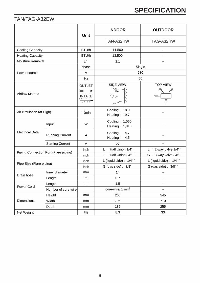
TAN/TAG-A32EW
Unit
BTU/hCooling Capacity
INDOOR OUTDOOR
–
BTU/hHeating Capacity –13,500
L/h
phase
Moisture Removal –
Power source
Single
V 230
Hz 50
OUTLET
Airflow Method
TOP VIEW
INTAKE
m/minAir circulation (at High)Cooling ;Heating ;
W
Electrical Data
Input
Running Current
Starting Current
Inner diameter
Length
Cooling ;–
–
Heating ;
ACooling ;
–
–
Heating ;
A
inchPiping Connection Port (Flare piping)
L L
inch G G
inchPipe Size (Flare piping)
inch
mmDrain hose
Length
Height
Width
Depth
Number of core-wirePower Cord
–
m –
m –
core-wire/ 1 mm –
mm
Dimensions mm
mm
kgNet Weight
3
2
; Half Union 1/4''
; Half Union 3/8''
L (liquid side) ; 1/4''
G (gas side) ; 3/8''
; 2-way valve 1/4''
; 3-way valve 3/8''
L (liquid side) ; 1/4''
G (gas side) ; 3/8''
11,500
2.1
27
8.09.7
1,0501,010
4.74.5
14
0.7
1.5
265
795
182
8.3
545
710
255
33
SIDE VIEW
TAN-A32HW TAG-A32HW

SPECIFICATION
– 6 –
Unit
Air Circulation
INDOOR OUTDOOR
Cross-flow Fan Propeller Fan
22 20
Induction (4-pole) Induction (6-pole)
W
Heat Exchanger19.5FPI 19.5 FPI
Capillary Tube
Plate fin configuration,forced draft
Refrigerant Control Device
g (oz)Refrigerant (R410A)
–
1,100(38.8)–
OLR(INNER)–
Thermostat
Protection Device
Air Filter
Parts Provided
Electronic Control
Type
Motor Type
Rated Output
–
Mold-proof –
Specifications are subject to change without notice.
1 Mounting plate2 Remote controller3 Battery (2 pcs.)4 Remote controller holder5 Screw cap (2 pcs.)6 Drain elbow
Timer –Real time dual ON/OFF7-hour OFF
TAN-A32HW TAG-A32HW
– 7 –
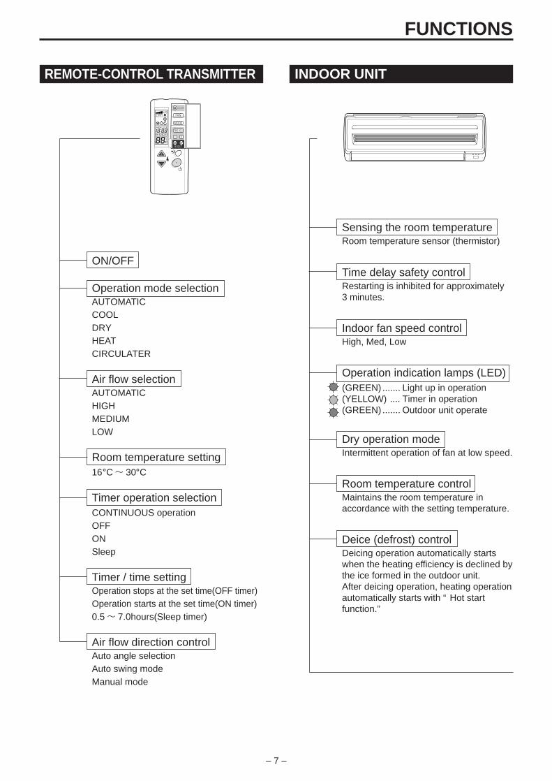
REMOTE-CONTROL TRANSMITTER
ON/OFF
Operation mode selectionAUTOMATICCOOLDRYHEATCIRCULATER
Air flow selectionAUTOMATICHIGHMEDIUMLOW
Room temperature setting16°C~ 30°C
Timer operation selectionCONTINUOUS operationOFFONSleep
Timer / time settingOperation stops at the set time(OFF timer)Operation starts at the set time(ON timer)0.5~ 7.0hours(Sleep timer)
Air flow direction controlAuto angle selectionAuto swing modeManual mode
INDOOR UNIT
Sensing the room temperatureRoom temperature sensor (thermistor)
Time delay safety controlRestarting is inhibited for approximately3 minutes.
Indoor fan speed controlHigh, Med, Low
Operation indication lamps (LED)(GREEN) ....... Light up in operation(YELLOW) .... Timer in operation(GREEN) ....... Outdoor unit operate
Dry operation modeIntermittent operation of fan at low speed.
Room temperature controlMaintains the room temperature inaccordance with the setting temperature.
Deice (defrost) controlDeicing operation automatically startswhen the heating efficiency is declined bythe ice formed in the outdoor unit.After deicing operation, heating operationautomatically starts with “Hot startfunction.”
FUNCTIONS
SET
ON
APMCLOCK
OFF
℃
L HMAUTO
MODE
FAN
TIME ADJ
ON OFF
LOUVER
– 8 –
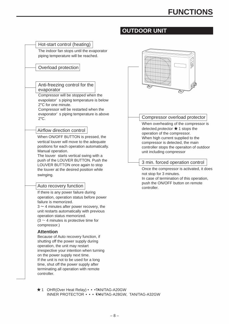
Hot-start control (heating)The indoor fan stops until the evaporatorpiping temperature will be reached.
Overload protection
Anti-freezing control for theevaporatorCompressor will be stopped when theevapolator’s piping temperature is below2°C for one minute.Compressor will be restarted when theevaporator’s piping temperature is above2°C.
Airflow direction controlWhen ON/OFF BUTTON is pressed, thevertical louver will move to the adequatepositions for each operation automatically.Manual operation.The louver starts vertical swing with apush of the LOUVER BUTTON. Push theLOUVER BUTTON once again to stopthe louver at the desired position whileswinging.
Auto recovery functionIf there is any power failure duringoperation, operation status before powerfailure is memorized.3~ 4 minutes after power recovery, theunit restarts automatically with previousoperation status memorized.(3~ 4 minutes is protective time forcompressor.)
AttentionBecause of Auto recovery function, ifshutting off the power supply duringoperation, the unit may restartirrespective your intention when turningon the power supply next time.If the unit is not to be used for a longtime, shut off the power supply afterterminating all operation with remotecontroller.
OUTDOOR UNIT
Compressor overload protectorWhen overheating of the compressor isdetected,protector ★ 1 stops theoperation of the compressor.When high current supplied to thecompressor is detected, the maincontroller stops the operaiton of outdoorunit including compressor
3 min. forced operation controlOnce the compressor is activated, it doesnot stop for 3 minutes.In case of termination of this operation,push the ON/OFF button on remotecontroller.
FUNCTIONS
★ 1 OHR(Over Heat Relay) • • • •INNER PROTECTOR • • • • •
TAN/TAG-A20GWTAN/TAG-A28GW, TAN/TAG-A32GW
– 9 –
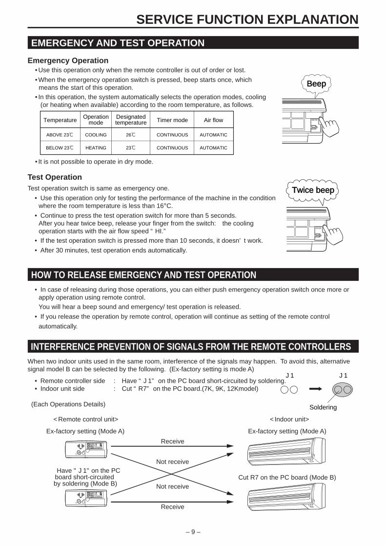
Emergency Operation •Use this operation only when the remote controller is out of order or lost.
•When the emergency operation switch is pressed, beep starts once, whichmeans the start of this operation.
•In this operation, the system automatically selects the operation modes, cooling (or heating when available) according to the room temperature, as follows.
•It is not possible to operate in dry mode.
Test OperationTest operation switch is same as emergency one.
• Use this operation only for testing the performance of the machine in the conditionwhere the room temperature is less than 16°C.
• Continue to press the test operation switch for more than 5 seconds.After you hear twice beep, release your finger from the switch: the coolingoperation starts with the air flow speed “HI.”
• If the test operation switch is pressed more than 10 seconds, it doesn’t work.
• After 30 minutes, test operation ends automatically.
When two indoor units used in the same room, interference of the signals may happen. To avoid this, alternativesignal model B can be selected by the following. (Ex-factory setting is mode A)
• Remote controller side : Have “J1” on the PC board short-circuited by soldering. • Indoor unit side : Cut “R7” on the PC board.(7K, 9K, 12Kmodel)
(Each Operations Details)
EMERGENCY AND TEST OPERATION
SERVICE FUNCTION EXPLANATION
Beep
Twice beep
<Remote control unit> <Indoor unit>
Receive
Ex-factory setting (Mode A) Ex-factory setting (Mode A)
Cut R7 on the PC board (Mode B)Have "J1"on the PC
board short-circuited by soldering (Mode B)
Receive
Not receive
Not receive
ON
APMCLOCK
OFF℃
LH
MAUTO℃
ON
APMCLOCK
OFF℃
LH
MAUTO℃
J1
Soldering
J1
Temperature
ABOVE 23℃
BELOW 23℃
COOLING
HEATING
26℃
23℃
CONTINUOUS
CONTINUOUS
AUTOMATIC
AUTOMATIC
Operation�mode
Designated�temperature Timer mode Air flow
HOW TO RELEASE EMERGENCY AND TEST OPERATION
INTERFERENCE PREVENTION OF SIGNALS FROM THE REMOTE CONTROLLERS
• In case of releasing during those operations, you can either push emergency operation switch once more orapply operation using remote control.
You will hear a beep sound and emergency/ test operation is released.
• If you release the operation by remote control, operation will continue as setting of the remote control
automatically.
– 10 –
OPERATION DETAILS
TIMER OPERATIONON Timer operation
•Press the ON/OFF switch.•Set the “ON Time” : Press the “TIME ADJ” button twice. Adjust the time with the “ , ” button. Press the “TIME ADJ” button twice.The setting of “ON Time” is completed and the present time appears on the LCD.•Set the “ON Timer” : Press the Timer fixing button “ON”.
OFF Timer operation•Press the ON/OFF switch.•Set the “OFF Time” : Press the “TIME ADJ” button 3 times. Adjust the time with the “ , ” button. Press the “TIME ADJ” button once.The setting of “OFF Time” is completed and the present time appears on the LCD.•Set the “OFF Timer” : Press the Timer fixing button “OFF”.
Sleep Timer operation•Press the “SLEEP” button during the operation.•Set the operating period by pressing the “SLEEP” button until the period appears on the LCD.
Timer Cancellation•ON/OFF Timer : Press the Timer fixing button “ON”(On Timer) and/or “OFF”(Off Timer) once again.
•Sleep Timer : Press the “SLEEP” button until the operating period on the LCD disappears.
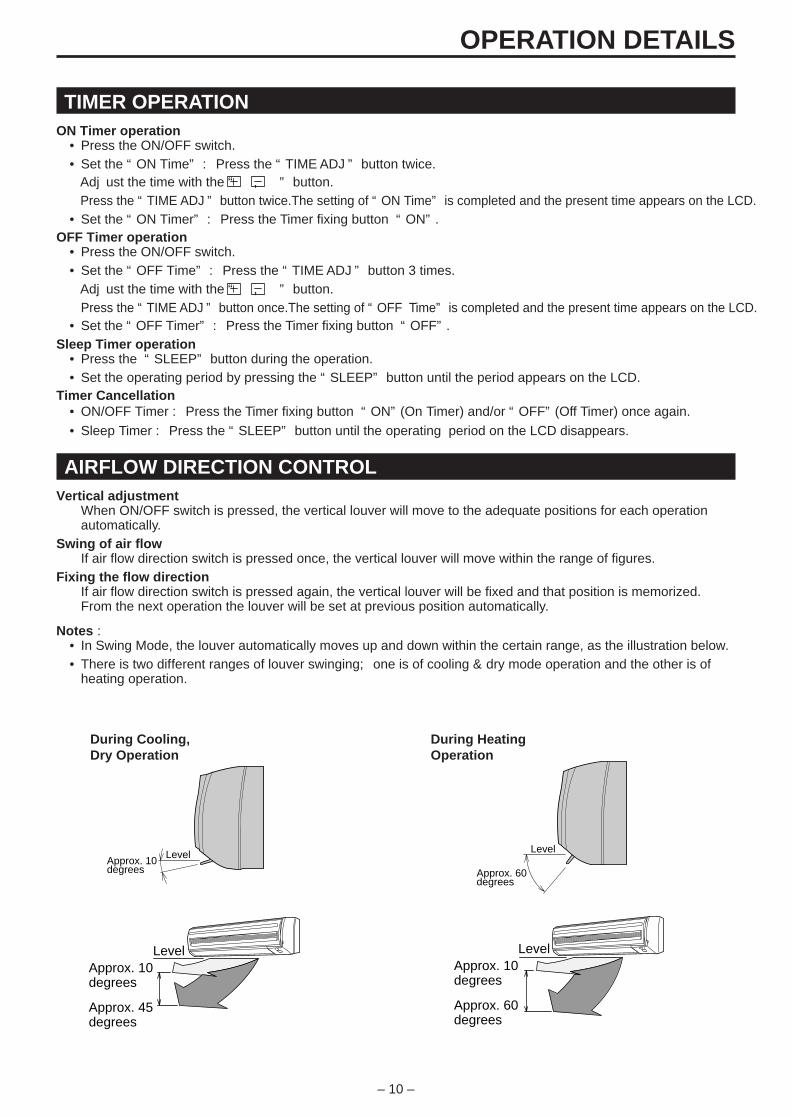
AIRFLOW DIRECTION CONTROLVertical adjustment
When ON/OFF switch is pressed, the vertical louver will move to the adequate positions for each operationautomatically.
Swing of air flowIf air flow direction switch is pressed once, the vertical louver will move within the range of figures.
Fixing the flow directionIf air flow direction switch is pressed again, the vertical louver will be fixed and that position is memorized.From the next operation the louver will be set at previous position automatically.
Notes :•In Swing Mode, the louver automatically moves up and down within the certain range, as the illustration below.•There is two different ranges of louver swinging; one is of cooling & dry mode operation and the other is of
heating operation.
LevelApprox. 10degrees
Level
Approx. 60degrees
LevelApprox. 10degrees
Approx. 45degrees
LevelApprox. 10degrees
Approx. 60degrees
During Cooling,Dry Operation
During HeatingOperation
– 11 –
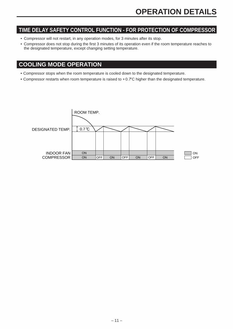
COOLING MODE OPERATION•Compressor stops when the room temperature is cooled down to the designated temperature.
•Compressor restarts when room temperature is raised to +0.7°C higher than the designated temperature.
OPERATION DETAILS
ROOM TEMP.
DESIGNATED TEMP.
INDOOR FAN ONON OFF ON ON ON
ONOFFCOMPRESSOR
0.7
OFF OFF
TIME DELAY SAFETY CONTROL FUNCTION - FOR PROTECTION OF COMPRESSOR•Compressor will not restart, in any operation modes, for 3 minutes after its stop.•Compressor does not stop during the first 3 minutes of its operation even if the room temperature reaches to
the designated temperature, except changing setting temperature.
– 12 –
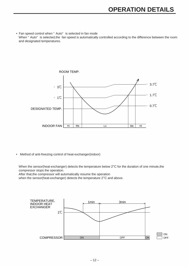
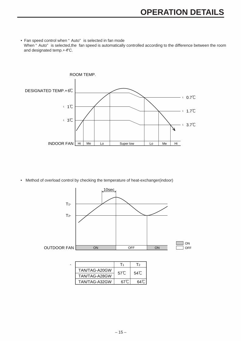
•Fan speed control when “Auto” is selected in fan mode When “Auto” is selected,the fan speed is automatically controlled according to the difference between the room and designated temperatures.
ROOM TEMP.
DESIGNATED TEMP.
Hi MeLo HiINDOOR FAN
+3℃
+1℃
+3.7℃
+1.7℃
+0.7℃
Me
• Method of anti-freezing control of heat-exchanger(indoor)
When the sensor(heat-exchanger) detects the temperature below 2°C for the duration of one minute,the compressor stops the operation. After that,the compressor will automatically resume the operation when the sensor(heat-exchanger) detects the temperature 2°C and above.
TEMPERATURE,�INDOOR HEAT�EXCHANGER
ON ONONOFFCOMPRESSOR
2℃
OFF
3min1min
OPERATION DETAILS
– 13 –
DESIGNATED TEMP.
(super low)
10min. 6min.
(super low) (super low) (super low) (super low)INDOOR FANCOMPRESSOR
0.7
2.0
ONOFFONON OFFOFF
OFF
ONONON
ON
OFF
OFF OFF
10min. 6min. 3min.
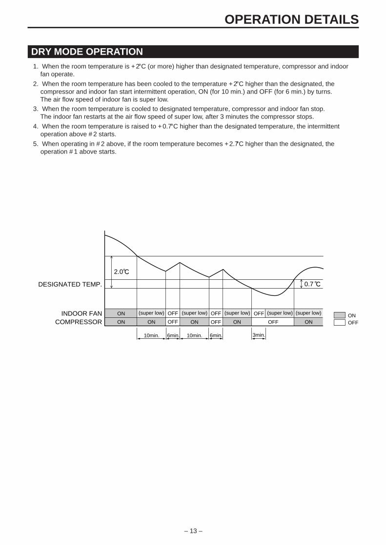
DRY MODE OPERATION1. When the room temperature is +2°C (or more) higher than designated temperature, compressor and indoor
fan operate.
2. When the room temperature has been cooled to the temperature +2°C higher than the designated, the compressor and indoor fan start intermittent operation, ON (for 10 min.) and OFF (for 6 min.) by turns. The air flow speed of indoor fan is super low.
3. When the room temperature is cooled to designated temperature, compressor and indoor fan stop. The indoor fan restarts at the air flow speed of super low, after 3 minutes the compressor stops.
4. When the room temperature is raised to +0.7°C higher than the designated temperature, the intermittent operation above #2 starts.
5. When operating in #2 above, if the room temperature becomes +2.7°C higher than the designated, the operation #1 above starts.
OPERATION DETAILS
– 14 –
0.7℃
6℃ Designated Temperature
Room Temperature
Max.4 min.★
INDOOR FAN Stop Superlow Low Designated by remote controller
★ : In maximum 4 minutes,the operation proceed to the next steps when the heat exchanger is not warmed up to the reference temperature shown above.
Max.4 min.★
ON
ON ONOFF OFF OFFON
OFF
COMPRESSOR
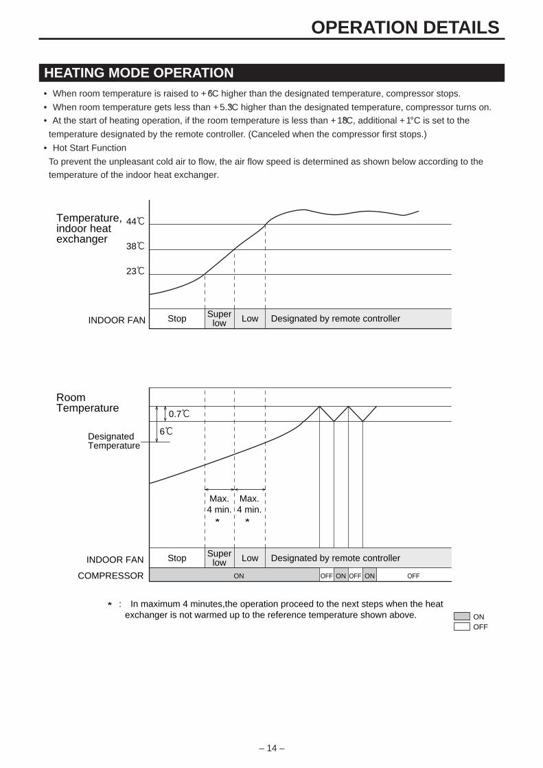
HEATING MODE OPERATION • When room temperature is raised to +6°C higher than the designated temperature, compressor stops.
• When room temperature gets less than +5.3°C higher than the designated temperature, compressor turns on.
• At the start of heating operation, if the room temperature is less than +18°C, additional +1°C is set to the
temperature designated by the remote controller. (Canceled when the compressor first stops.)
• Hot Start Function
To prevent the unpleasant cold air to flow, the air flow speed is determined as shown below according to the
temperature of the indoor heat exchanger.
Temperature,indoor heat exchanger
38℃
23℃
44℃
INDOOR FAN Stop Superlow Low Designated by remote controller
OPERATION DETAILS
– 15 –
• Method of overload control by checking the temperature of heat-exchanger(indoor)
ON ONONOFFOUTDOOR FAN
TAN/TAG-A20GWTAN/TAG-A28GW
T1※
57℃
T2
54℃
T2※
OFF
T1※
10sec
TAN/TAG-A32GW 67℃ 64℃
OPERATION DETAILS
•Fan speed control when “Auto” is selected in fan mode When “Auto” is selected,the fan speed is automatically controlled according to the difference between the room and designated temp.+4°C.
ROOM TEMP.
DESIGNATED TEMP.+6℃
Hi MeLo Super low Lo HiINDOOR FAN
-1℃
-3℃
-0.7℃
-1.7℃
-3.7℃
Me
– 16 –
OPERATION DETAILS
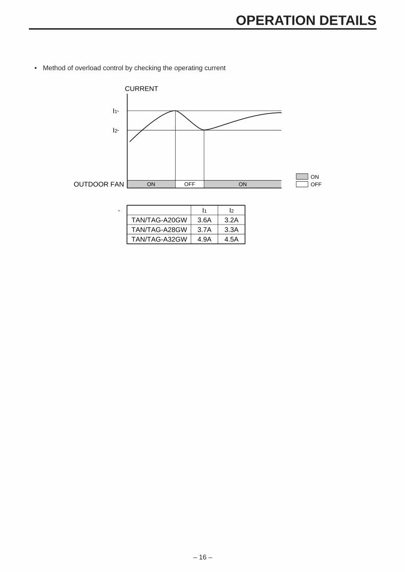
• Method of overload control by checking the operating current
ON ONONOFFOUTDOOR FAN
CURRENT
I13.6A3.7A4.9A
I23.2A3.3A4.5A
I2※
OFF
I1※
※ TAN/TAG-A20GWTAN/TAG-A28GWTAN/TAG-A32GW
– 17 –
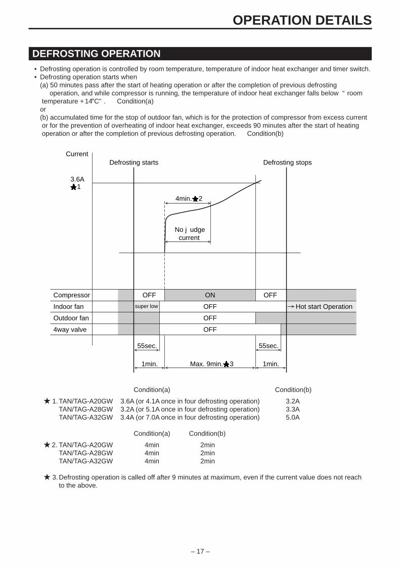
Condition(a) Condition(b)
TAN/TAG-A20GW 3.6A (or 4.1A once in four defrosting operation) 3.2ATAN/TAG-A28GW 3.2A (or 5.1A once in four defrosting operation) 3.3ATAN/TAG-A32GW 3.4A (or 7.0A once in four defrosting operation) 5.0A
Condition(a) Condition(b)
TAN/TAG-A20GW 4min 2minTAN/TAG-A28GW 4min 2minTAN/TAG-A32GW 4min 2min
Defrosting operation is called off after 9 minutes at maximum, even if the current value does not reachto the above.
DEFROSTING OPERATION•Defrosting operation is controlled by room temperature, temperature of indoor heat exchanger and timer switch.•Defrosting operation starts when
(a) 50 minutes pass after the start of heating operation or after the completion of previous defrosting operation, and while compressor is running, the temperature of indoor heat exchanger falls below “room
temperature +14°C”. Condition(a)or(b) accumulated time for the stop of outdoor fan, which is for the protection of compressor from excess current or for the prevention of overheating of indoor heat exchanger, exceeds 90 minutes after the start of heating operation or after the completion of previous defrosting operation. Condition(b)
Compressor
Defrosting starts
No judge current
Current
3.6A1
4min. 2
55sec.
1min. Max. 9min. 3
Defrosting stops
Indoor fan
OFF OFFON
OFF Hot start Operation
OFF
OFF
super low
Outdoor fan
4way valve
55sec.
1min.
★ 1.
★ 2.
★ 3.
OPERATION DETAILS
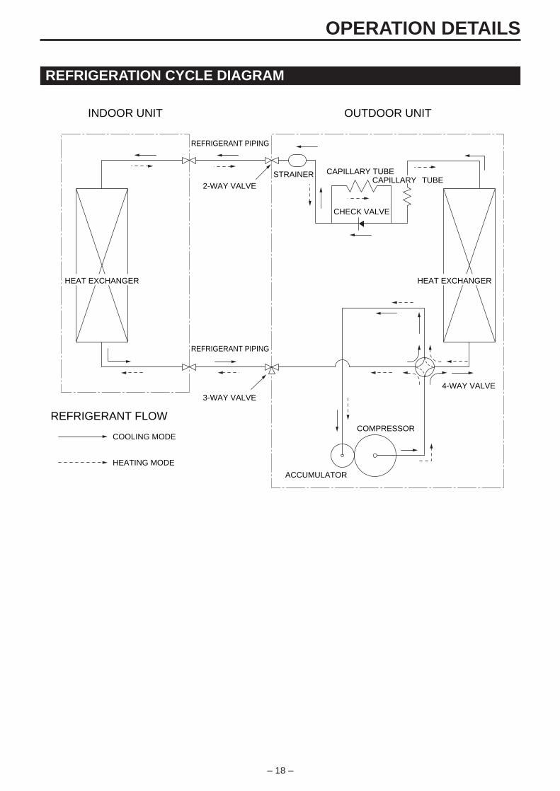
– 18 –
REFRIGERATION CYCLE DIAGRAM
INDOOR UNIT
REFRIGERANT PIPING
REFRIGERANT PIPING
2-WAY VALVE
3-WAY VALVE
COOLING MODE
HEATING MODE
4-WAY VALVE
STRAINER CAPILLARY TUBECAPILLARY
ACCUMULATOR
COMPRESSORREFRIGERANT FLOW
OUTDOOR UNIT
HEAT EXCHANGER
CHECK VALVE
HEAT EXCHANGER
TUBE
OPERATION DETAILS
– 19 –
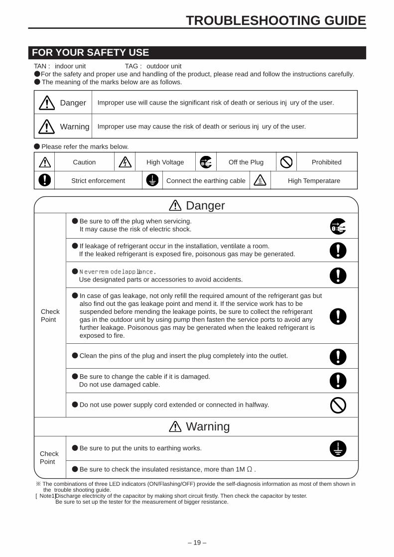
TROUBLESHOOTING GUIDE
FOR YOUR SAFETY USETAN : indoor unit TAG : outdoor unit●For the safety and proper use and handling of the product, please read and follow the instructions carefully.● The meaning of the marks below are as follows.
●Never remodel appliance. Use designated parts or accessories to avoid accidents.
● In case of gas leakage, not only refill the required amount of the refrigerant gas butalso find out the gas leakage point and mend it. If the service work has to besuspended before mending the leakage points, be sure to collect the refrigerantgas in the outdoor unit by using pump then fasten the service ports to avoid anyfurther leakage. Poisonous gas may be generated when the leaked refrigerant isexposed to fire.
●Clean the pins of the plug and insert the plug completely into the outlet.
●Be sure to change the cable if it is damaged. Do not use damaged cable.
●Do not use power supply cord extended or connected in halfway.
●Be sure to put the units to earthing works.
●Be sure to check the insulated resistance, more than 1MΩ .
Warning
※ The combinations of three LED indicators (ON/Flashing/OFF) provide the self-diagnosis information as most of them shown in the trouble shooting guide.[Note1]
CheckPoint
CheckPoint
●Be sure to off the plug when servicing.It may cause the risk of electric shock.
● If leakage of refrigerant occur in the installation, ventilate a room. If the leaked refrigerant is exposed fire, poisonous gas may be generated.
Danger
Improper use will cause the significant risk of death or serious injury of the user.Danger
Warning Improper use may cause the risk of death or serious injury of the user.
Caution ProhibitedHigh Voltage
Strict enforcement Connect the earthing cable
Off the Plug
●Please refer the marks below.
High Temperatare
Discharge electricity of the capacitor by making short circuit firstly. Then check the capacitor by tester.Be sure to set up the tester for the measurement of bigger resistance.
– 20 –
TROUBLESHOOTING GUIDE
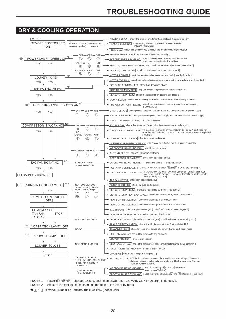
POWER TIMER OPERATION (green) (yellow) (green)
NO
OFF OFF OFF
ON OFF
FLASHING
NO ROTATION orSLOW ROTATION
[NOTE.1]
NOT COOL ENOUGH
NOT COOL ENOUGH
NOT DRAIN ENOUGH
COOL AIR DOSEN'T COME OUT
(OPERATING INHEATING MODE)
TAN FAN REPEATED"OPERATION" AND "STOP"
NOISE
outdoor unit stops beforereaching set up temp.
check the plug inserted into the outlet and the power supply
if the battery is dead or failure in remote controller change to new one
check the fuse by eyes or cheak the electric continuity by tester
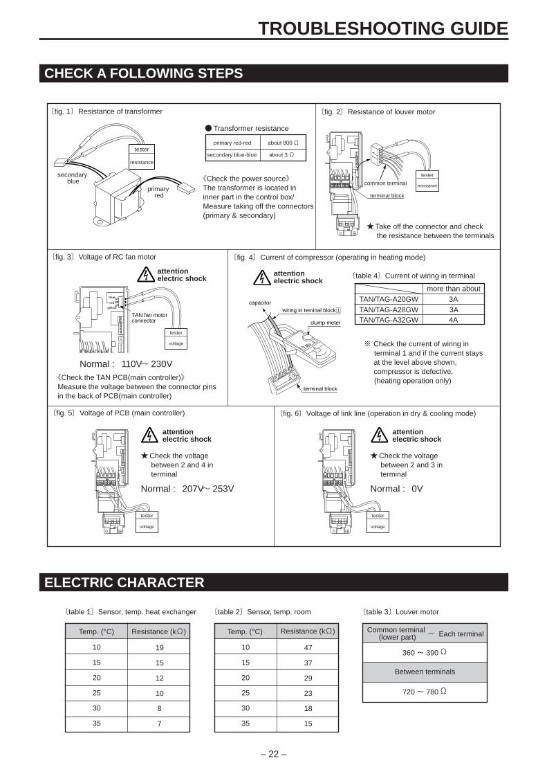
check the resistance by tester [see fig.1]
other than described above [how to operate emergency operation test operation]
OFF OFF OFF
FLASHING OFF OFF
FLASHING ON ONcheck the resistance by tester [see table 1]
check the resistance by tester [see table 2]
check the resistance between two terminals [see fig.2,table 3]
check the voltage between blue's connection and yellow one. [see fig.3]
adjust proper temperature in remote controller
check the resistance by tester [see table 2]
check the restarting operation of compressor, after passing 3 minute
check the resistance of sensor (temp. heat exchanger)[see table 1]
check proper voltage of power supply and use an exclusive power supply
check proper voltage of power supply and use an exclusive power supply
check by eyes
check the pressure of gas [check「performance curve diagram」]
if the scale of the tester swings instantly to "zeroΩ" and does not move back to "infinity", capacitor for compressor should be replaced [NOTE.2]
other than described above
leak of gas, or cut off of overheat prevention relay
check the wiring order
change PCB(main controller)
other than described above
check by eyes and clean it
check the resistance by tester [see table 2]
check the resistance by tester [see table 1]
check the blockage of air outlet of TAN
check the blockage of air inlet & air outlet of TAG
check the pressure of gas [check「performance curve diagram」]
other than described above
check the pressure of gas [check「performance curve diagram」]
check the blockage of air inlet & air outlet of TAG
check by eyes after power off. turn by hands and check noise
check by eyes around the pipes with any obstacles
level louver position
check the pressure of gas [check「performance curve diagram」]
check the level of TAN
check the drain pipe is stopped up
if DC5V is achieved between black and brown lead wiring of fan motor,while no voltage of pulse between white and black wiring, then TAN fanmotor should be replaced
check the voltage between 2 and 3 in terminal [see fig. 6]
check the wiring of 3 and 4 in terminal(not turning TAG fan)
other than described above
check the wiring order(NO ROTAION)
if the scale of the tester swings instantly to "zeroΩ" and doesnot move back to "infinity", capacitor for TAG fan motor shouldbe replaced [NOTE.2]
other than described above
check the voltage between 2 and 4 in terminals [see fig.5]
ON
OR
OFF OFF
FLASHING FLASHING OFF
OFF
[NOTE.1] If alarm " " appears 15 sec. after main power on, PCB(MAIN CONTROLLER) is defective.[NOTE.2] Measure the resistance by changing the pole of the tester by turns.
OFF FLASHING
1 ~ 4 Terminal Number on Terminal Block of TAN. (indoor unit)★
YES
STOP
REMOTE CONTROLLER「ON」
YES
"POWER LAMP" GREEN ON
LOUVER「OPEN」
TAN FAN ROTATING
"OPERATION LAMP" GREEN ON
TAG FAN ROTATING
COMPRESSOR IS WORKING
OPERATING IN DRY MODE
OPERATING IN COOLING MODE
REMOTE CONTROLLER「OFF」
COMPRESSORTAN FAN STOPTAG FAN
"OPERATION LAMP" OFF
"POWER LAMP" OFF
LOUVER「CLOSE」
NO
NO
NO
NO
NO
NO
YESYES
YESYES
YESYES
YESYES
YES
YES
YES
FILTER IS CHOKED
SENSOR, TEMP. ROOM
SENSOR, TEMP. HEAT EXCHANGER
PLACE OF INSTALLATION
PLACE OF INSTALLATION
EXCESS GAS
COMPRESSOR BREAKDOWN
SHORTAGE OF GAS
PLACE OF INSTALLATION
TANGENTIAL FAN
PIPE
LOUVER POSITION
SHORTAGE OF GAS
INSUFFICIENT INSTALLATION
DRAINAGE
TAN FAN MOTOR
SETTING TEMPERATURE
SENSOR, TEMP. ROOM
COMPRESSOR
PREVENTION FOR FREEZING
WRONG WIRING CONNECTION
PCB (MAIN CONTROLLER)
CAPACITOR, TAG FAN MOTOR
DROP VOLTAGE
BY DROP VOLTAGE
DEFECTIVE WIRING CONTACTS
EXCESS GAS
CAPACITOR, COMPRESSOR
POWER SUPPLY
REMOTE CONTROL
FUSE (2.0A)
TRANSFORMER
PCB (RECEIVER & DISPLAY)
SENSOR, TEMP. HEAT EXCHANGER
SENSOR, TEMP. ROOM
MOTOR, LOUVER
MOTOR, TAN FAN
PCB (MAIN CONTROLLER)
COMPRESSOR LOCKING
OVERHEAT PREVENTION RELAY
WRONG WIRING CONNECTION
CUTTING OFF CT
COMPRESSOR BREAKDOWN
TAG FAN MOTOR
WRONG WIRING CONNECTION
SHORT CIRCUIT OF WIRINGS
DRY & COOLING OPERATION
– 21 –
TROUBLESHOOTING GUIDE
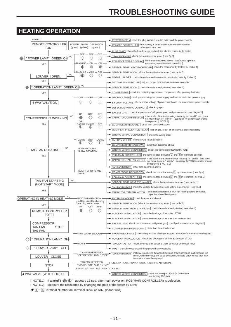
POWER TIMER OPERATION (green) (yellow) (green)
OFF OFF OFF
ON OFF
ON
OR
OFF OFF
FLASHING FLASHING OFF
FLASHING FLASHING
NO ROTATION orSLOW ROTATION
SLIGHTLY TURN ANDSTOP
NOT WARM ENOUGH
NOT WARM ENOUGH
NOISE
REPEATED "HEATING" AND "COOLING"
TAG FAN REPEATED"OPERATION" AND "STOP"
TAG FAN REPEATED"OPERATION" AND "STOP"
outdoor unit stops beforereaching set up temp.
POWER SUPPLY check the plug inserted into the outlet and the power supply
REMOTE CONTROLLER
FUSE (2.0A)
TRANSFORMER
PCB (RECEIVER & DISPLAY)
if the battery is dead or failure in remote controller change to new one
check the fuse by eyes or cheak the electric continuity by tester
check the resistance by tester [see fig.1]
other than described above [See「how to operate emergency operation test operation」]
OFF OFF OFF
FLASHING OFF OFF
FLASHING ON ON
SENSOR, TEMP. HEAT EXCHANGER
SENSOR, TEMP. ROOM
MOTOR, LOUVER
SETTING TEMPERATURE
SENSOR, TEMP. ROOM
COMPRESSOR
DROP VOLTAGE
BY DROP VOLTAGE
DEFECTIVE WIRING CONTACTS
EXCESS GAS
CAPACITOR, COMPRESSOR
COMPRESSOR LOCKING
OVERHEAT PREVENTION RELAY
WRONG WIRING CONNECTION
CUTTING OFF CT
COMPRESSOR BREAKDOWN
WRONG WIRING CONNECTION
PCB (MAIN CONTROLLER)
CAPACITOR, TAG FAN MOTOR
TAN FAN MOTOR
COMPRESSOR BREAKDOWN
PCB (MAIN CONTROLLER)
SENSOR, TEMP. HEAT EXCHANGER
TAN FAN MOTOR
CAPACITOR, TAN FAN MOTOR
check the resistance by tester [see table 1]
check the resistance by tester [see table 2]
check the resistance between two terminals [see fig.2,table 3]
adjust proper temperature in remote controller
check the resistance by tester [see table 2]
check by eyes
check proper voltage of power supply and use an exclusive power supply
check proper voltage of power supply and use an exclusive power supply
check the restarting operation of compressor, after passing 3 minutes
if the scale of the tester swings instantly to "zeroΩ" and does not move back to "infinity" , capacitor for compressor should be replaced [NOTE.2]
other than described above
other than descrived above
check the pressure of refrigerant gas [see「performance curve diagram」]
if the scale of the tester swings instantly to "zeroΩ" and doesnot move back to "infinity", capacitor for TAG fan motor should be replaced [NOTE.2]
other than described above
leak of gas, or cut off of overheat prevention relay
check the wiring order(NO ROTATION)
check the wiring order
change PCB (main controller)
check by eyes and clean it
check the voltage between blue and yellow in connector [see fig.3]
check the resistance by tester [see table 1]
after starts operation, if TAN fan rotate properly by hands,capacitor should be replaced
check the resistance by tester [see table 2]
check the resistance by tester [see table 1]
check the blockage of air outlet of TAN
check the blockage of air inlet & air outlet of TAG
check the pressure of refrigerant gas [check「performance curve diagram」]
other than described above
check the pressure of refrigerant gas [check「performance curve diagram」]
check the blockage of air inlet & air outlet of TAG
check by eyes after power off. turn by hands and check noise
check by eyes around the pipes with any obstacles
if DC5V is achieved between black and brown portion of lead wiring of fanmotor, while no voltage of pulse between white and black wiring, then TAN fan motor should be replaced
UNDER "POWER SAVE" MODE (NOTHING ABNORMAL)
check the voltage between 2 and 4 in terminals [see fig.5]
check the voltage between 2 and 4 in terminal [see fig.5]
check the current at wiring 1 by clamp meter [see fig.4]
OFF
OFF
REMOTE CONTROLLER「ON」
"POWER LAMP" GREEN ON
LOUVER「OPEN」
"OPERATION LAMP" GREEN ON
4-WAY VALVE ON
TAG FAN ROTATING
COMPRESSOR IS WORKING
OPERATING IN HEATING MODE
REMOTE CONTROLLER「OFF」
TAN FAN STARTING(HOT START MODE)
COMPRESSORTAN FAN STOP TAG FAN
"OPERATION LAMP" OFF
"POWER LAMP" OFF
LOUVER「CLOSE」
STOP
4-WAY VALVE (WITH COIL) OFF
NO
YES
NO
YES
NO
YES
NO
YES
NO
YES
NO
YES
NO
YES
[NOTE.1] If alarm " " appears 15 sec. after main power on, PCB(MAIN CONTROLLER) is defective.[NOTE.2] Measure the resistance by changing the pole of the tester by turns.
1 ~ 4 Terminal Number on Terminal Block of TAN. (indoor unit)★
[NOTE.1]
check the wiring of 3 and 4 in terminal(not turning TAG fan)
FILTER IS CHOKED
SENSOR, TEMP. ROOM
SENSOR, TEMP. HEAT EXHANGER
PLACE OF INSTALLATION
PLACE OF INSTALLATION
EXCESS GAS
COMPRESSOR BREAKDOWN
SHORTAGE OF GAS
PLACE OF INSTALLATION
TANGENTIAL FAN
PIPE
TAN FAN MOTOR
WRONG WIRING CONNECTION
HEATING OPERATION
– 22 –
TROUBLESHOOTING GUIDE
tester
voltage
47
37
29
23
18
15
19
15
12
10
8
7
CHECK A FOLLOWING STEPS
tester
resistance
primary red
secondary blue
★ Take off the connector and check the resistance between the terminals
〔fig. 3〕 Voltage of RC fan motor 〔fig. 4〕 Current of compressor (operating in heating mode)
〔fig. 1〕 Resistance of transformer 〔fig. 2〕 Resistance of louver motor
primary red-red
secondary blue-blue
● Transformer resistance
about 800Ω
about 3Ω
〔fig. 5〕 Voltage of PCB (main controller)
《Check the power source》The transformer is located ininner part in the control box/Measure taking off the connectors(primary & secondary)
〔fig. 6〕 Voltage of link line (operation in dry & cooling mode)
※ Check the current of wiring in terminal 1 and if the current stays
at the level above shown, compressor is defective.
(heating operation only)《Check the TAN PCB(main controller)》Measure the voltage between the connector pinsin the back of PCB(main controller)
capacitor
clump meter
terminal block
wiring in teminal block 1
Normal : 110V~ 230V
Normal : 207V~ 253V
attentionelectric shock
attentionelectric shock
ELECTRIC CHARACTER
attentionelectric shock
〔table 1〕Sensor, temp. heat exchanger 〔table 2〕Sensor, temp. room 〔table 3〕Louver motor
~ Each terminal
360 ~ 390Ω
Between terminals
720 ~ 780Ω
Common terminal (lower part)
Resistance (kΩ)
10
15
20
25
30
35
Temp. (°C) Resistance (kΩ)
10
15
20
25
30
35
Temp. (°C)
yellow
blue
red
tester
voltage
TAN fan motor connector
common terminal
tester
resistance
terminal block
tester
voltage
★Check the voltage between 2 and 4 in terminal
Normal : 0V
attentionelectric shock
★Check the voltage between 2 and 3 in terminal
〔table 4〕Current of wiring in terminal
more than about3A3A4A
TAN/TAG-A20GWTAN/TAG-A28GWTAN/TAG-A32GW
– 23 –
TROUBLESHOOTING GUIDE
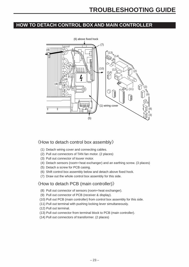
《How to detach control box assembly》
(1) Detach wiring cover and connecting cables.(2) Pull out connectors of TAN fan motor. (2 places)(3) Pull out connector of louver motor.(4) Detach sensors (room+heat exchanger) and an earthing screw. (3 places)(5) Detach a screw for PCB casing.(6) Shift control box assembly below and detach above fixed hock.(7) Draw out the whole control box assembly for this side.
《How to detach PCB (main controller)》 (8) Pull out connector of sensors (room+heat exchanger). (9) Pull out connector of PCB (receiver & display).(10) Pull out PCB (main controller) from control box assembly for this side.(11) Pull out terminal with pushing locking lever simultaneously.(12) Pull out terminal.(13) Pull out connector from terminal block to PCB (main controller).(14) Pull out connectors of transformer. (2 places)
HOW TO DETACH CONTROL BOX AND MAIN CONTROLLER
(6) above fixed hock
(1) wiring cover
(4)
(5)
(4)
(4)
(7)
(14)(10)
(2)(12)
(8)
(3)
(2)
(9)
(14)(13)
(11)
– 24 –
TROUBLESHOOTING GUIDE
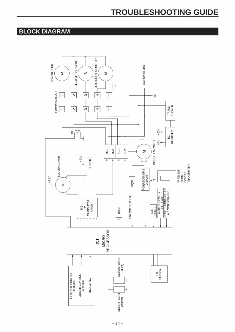
BLOCK DIAGRAM
IC1
IC2
7ch
TRA
NS
ISTO
RA
RR
AY
+12
V
+12
V
CT1
TER
MIN
AL
BLO
CK
CO
MP
RE
SS
OR
4 V
ALV
E S
OLE
NO
ID
OU
T D
OO
R F
AN
MO
TOR
IND
OO
R F
AN
MO
TOR
BU
ZZE
R
RL1
RL2
PC
1D
Q32
DQ
33
PC
2
+5V
DC
RE
CTI
FIE
RTR
AN
SFO
RM
ER
+12
V
LOU
VE
R C
ON
TRO
LC
HA
NG
E
IC31
RE
SE
T
AU
TO R
EC
OV
ER
YO
FF C
HA
GE
PC
B(R
EC
EIV
ER
&D
ISP
LAY
)
RE
MO
TE C
ON
TRO
LLE
RA
/B M
OD
E C
HA
NG
E
IC3
EE
PR
OM
MA
NU
AL
SW
EX
TER
NA
L C
ON
TRO
LC
HA
NG
E
SE
SO
R(T
EM
P.)
(RO
OM
)S
ES
OR
(TE
MP
.) (E
VA
)
WIR
ELE
SS
RE
MO
TEC
ON
TRO
LTR
AN
SM
ITTE
R
LOU
VE
R M
OTO
R
FAN
MO
TOR
PU
LSE
AC
PO
WE
R L
INE
MM
11
22
33
44
S M
M
MIC
RO
PR
OC
ES
SO
R
– 25 –
TROUBLESHOOTING GUIDE
R
SC R W
COMPRESSOR
B
CAPACITOR 30μF 400VAC
BLG/Y
↓INDOOR UNIT
1234TERMINAL BLOCK
MOTOR(FAN)
W W
4-WAY VALVE
BL
EARTH TERMINAL
WBR B
CAPACITOR 1.5μF 440VAC
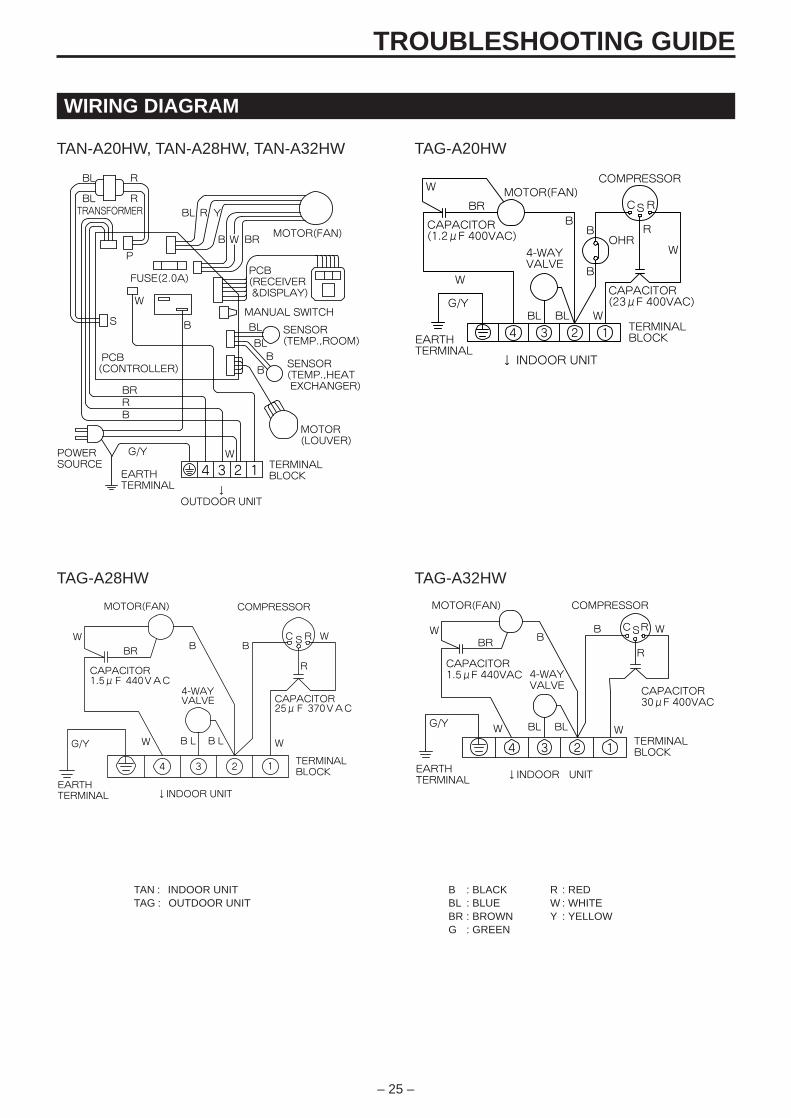
WIRING DIAGRAM
TAG-A28HW
TAG-A20HW
TAG-A32HW
↓ INDOOR UNIT
W
BL
RSC
R OHR
W G/Y
CAPACITOR (1.2μF 400VAC)
COMPRESSOR
4-WAY VALVE
B
W
CAPACITOR (23μF 400VAC)
BR
BL
BW
MOTOR(FAN)
B
EARTH TERMINAL
TERMINAL BLOCK14 23
BBLBRG
:BLACK:BLUE:BROWN:GREEN
TAN-A20HW, TAN-A28HW, TAN-A32HW
P
MOTOR (LOUVER)
SENSOR (TEMP.,HEAT EXCHANGER)
BB
SENSOR (TEMP.,ROOM)BL
MANUAL SWITCH
PCB (RECEIVER &DISPLAY)
MOTOR(FAN)B
YRBLTRANSFORMERR
R
BL
BL
W
↓ OUTDOOR UNIT
TERMINAL BLOCK
PCB (CONTROLLER)
S
FUSE(2.0A)
EARTH TERMINAL
POWER SOURCE
G/Y
B
BR
B
BRR
BL
4 3W
2 1
W
RWY
:RED:WHITE:YELLOW
TAN : INDOOR UNITTAG : OUTDOOR UNIT
CAPACITOR25μF 370VAC
CAPACITOR1.5μF 440VAC
B BBR
W
COMPRESSOR
EARTHTERMINAL
BL
WRC S
4-WAYVALVE
W
R
W
MOTOR(FAN)
TERMINALBLOCK4 3 2 1
↓INDOOR UNIT
G/Y BL
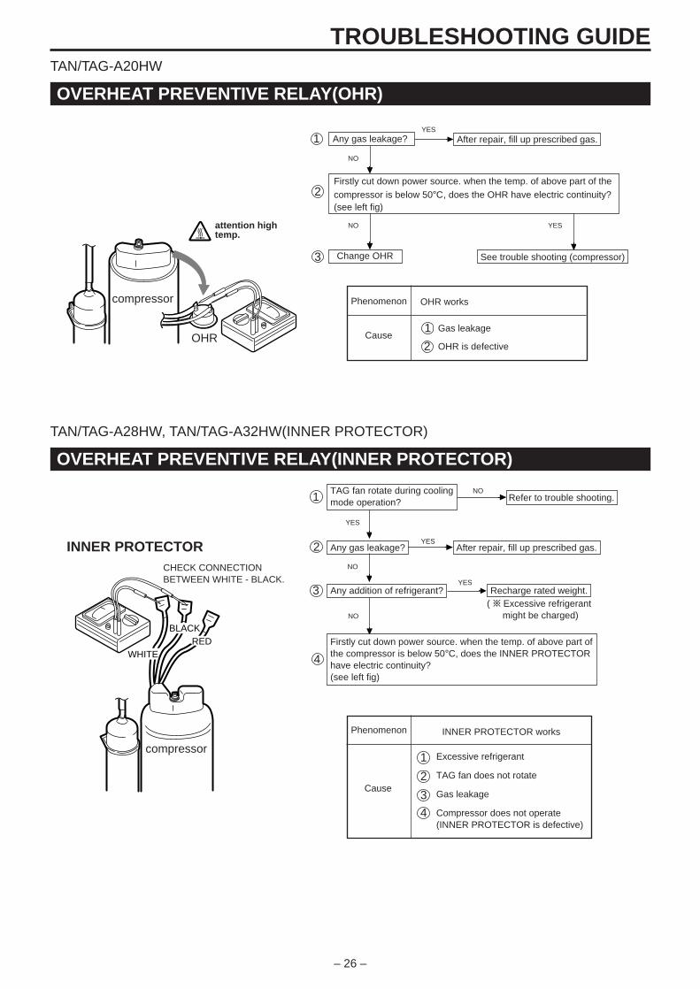
– 26 –
TROUBLESHOOTING GUIDE
Recharge rated weight.
OVERHEAT PREVENTIVE RELAY(INNER PROTECTOR)
Phenomenon OHR works
Gas leakage
OHR is defectiveCause
1
2
Refer to trouble shooting.
Any gas leakage?YES
After repair, fill up prescribed gas.2
OVERHEAT PREVENTIVE RELAY(OHR)
compressor
OHR
NO
Any gas leakage?YES
Firstly cut down power source. when the temp. of above part of thecompressor is below 50°C, does the OHR have electric continuity?(see left fig)
NO
See trouble shooting (compressor)
YES
After repair, fill up prescribed gas.
attention hightemp.
Change OHR
1
2
3
TAN/TAG-A20HW
NO
YES
NO
BLACKRED
WHITE
CHECK CONNECTIONBETWEEN WHITE - BLACK.
TAN/TAG-A28HW, TAN/TAG-A32HW(INNER PROTECTOR)
INNER PROTECTOR
TAG fan rotate during coolingmode operation?1
YESAny addition of refrigerant?3
Phenomenon INNER PROTECTOR works
Excessive refrigerant
TAG fan does not rotate
Gas leakage
Compressor does not operate(INNER PROTECTOR is defective)
Cause
NO
Firstly cut down power source. when the temp. of above part ofthe compressor is below 50°C, does the INNER PROTECTORhave electric continuity?(see left fig)
4
4
3
2
1compressor
(※Excessive refrigerant might be charged)
– 27 –
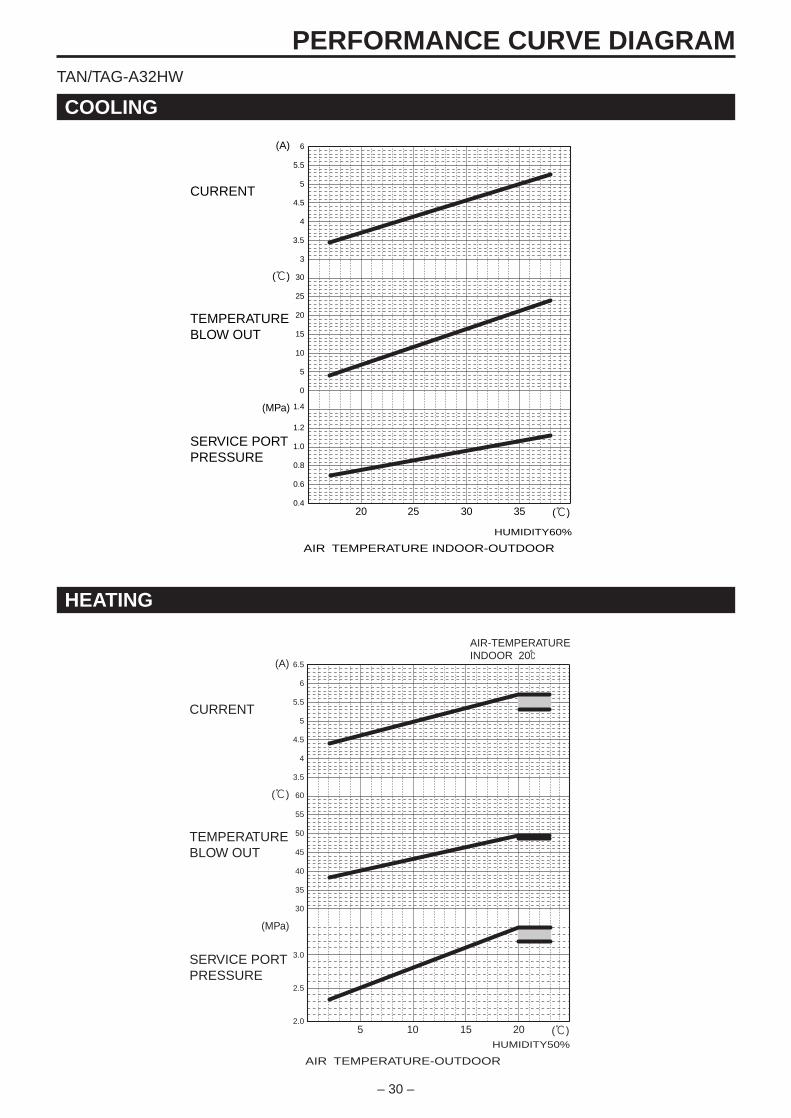
PERFORMANCE CURVE DIAGRAM
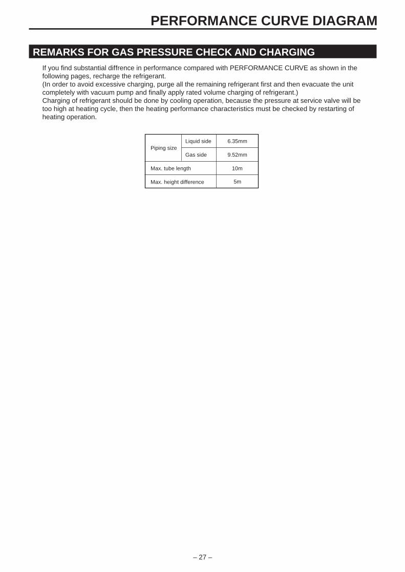
REMARKS FOR GAS PRESSURE CHECK AND CHARGINGIf you find substantial diffrence in performance compared with PERFORMANCE CURVE as shown in thefollowing pages, recharge the refrigerant.(In order to avoid excessive charging, purge all the remaining refrigerant first and then evacuate the unitcompletely with vacuum pump and finally apply rated volume charging of refrigerant.)Charging of refrigerant should be done by cooling operation, because the pressure at service valve will betoo high at heating cycle, then the heating performance characteristics must be checked by restarting ofheating operation.
Piping size
Max. tube length
6.35mmLiquid side
Gas side
Max. height difference
9.52mm
10m
5m
– 28 –
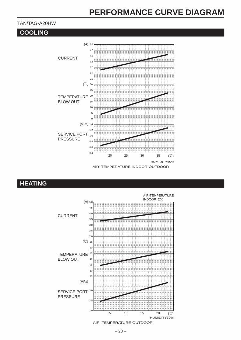
PERFORMANCE CURVE DIAGRAMTAN/TAG-A20HW
HEATING
COOLING
20 25 30 35
0
5
10
15
20
25
30
2.0
2.5
3.0
3.5
4.0
4.5
5.5
CURRENT
TEMPERATURE �BLOW OUT�
AIR TEMPERATURE INDOOR-OUTDOOR
HUMIDITY60%
(℃)0.4
0.6
0.8
1.0
1.2
1.4
�SERVICE PORT�PRESSURE
(A)
(℃)
(MPa)
5 10 15 20
AIR TEMPERATURE-OUTDOOR
HUMIDITY50%
(℃)
AIR-TEMPERATURE�INDOOR 20℃
2.0
2.5
3.0
25
30�
35
40
45
50
55
3.0
4.0
5.0
3.5
4.5
(℃)
2.0
2.5
(MPa)
CURRENT
TEMPERATURE �BLOW OUT
SERVICE PORT�PRESSURE
(A)
– 29 –
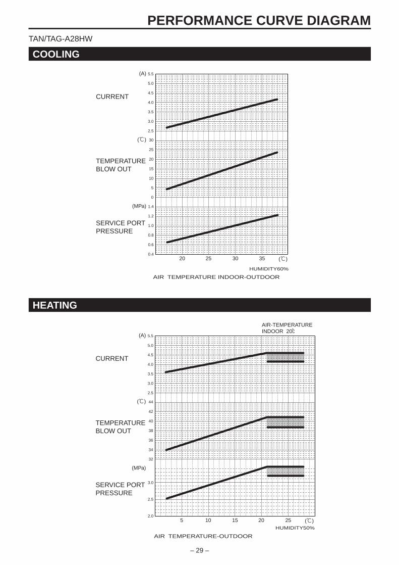
PERFORMANCE CURVE DIAGRAMTAN/TAG-A28HW
HEATING
COOLING
20 25 30 35
0
5
10
15
20
25
30
CURRENT
TEMPERATURE �BLOW OUT�
AIR TEMPERATURE INDOOR-OUTDOOR
HUMIDITY60%
(℃)0.4
0.6
0.8
1.0
1.2
1.4
�SERVICE PORT�PRESSURE
(℃)
(MPa)
2.5
3.0
3.5
4.0
4.5
5.0
5.5(A)
5 10 15 20 25
AIR TEMPERATURE-OUTDOOR
HUMIDITY50%
(℃)
AIR-TEMPERATURE�INDOOR 20℃
2.0
2.5
3.0
32
34
36
38
40
42
44(℃)
(MPa)
CURRENT
TEMPERATURE �BLOW OUT
SERVICE PORT�PRESSURE
(A)
3.0
4.0
5.0
3.5
4.5
5.5
2.5
– 30 –
PERFORMANCE CURVE DIAGRAM
HEATING
COOLING
20 25 30 35
0
5
10
15
20
25
30
3
3.5
4
4.5
5
5.5
6
CURRENT
TEMPERATURE �BLOW OUT�
AIR TEMPERATURE INDOOR-OUTDOOR
HUMIDITY60%
(℃)0.4
0.6
0.8
1.0
1.2
1.4
SERVICE PORT�PRESSURE
(MPa)
�
(A)
(℃)
5 10 15 202.0
2.5
3.0
30
35 �
40
45
50
55
60
4.5
5.5
6.5
5
6
AIR TEMPERATURE-OUTDOOR
HUMIDITY50%
(℃)
AIR-TEMPERATURE�INDOOR 20℃
(℃)
3.5
4
(MPa)
CURRENT
TEMPERATURE �BLOW OUT
SERVICE PORT�PRESSURE
(A)
TAN/TAG-A32HW
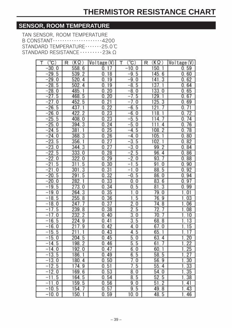
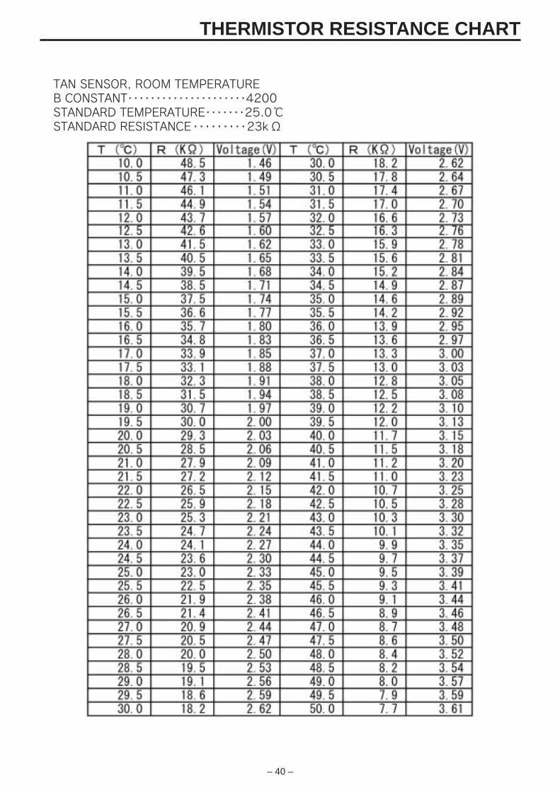
– 39 –
SENSOR, ROOM TEMPERATURE
THERMISTOR RESISTANCE CHART
TAN SENSOR, ROOM TEMPERATUREB CONSTANT・・・・・・・・・・・・・・・・・・・・・4200STANDARD TEMPERATURE・・・・・・・25.0℃STANDARD RESISTANCE・・・・・・・・・23kΩ
– 40 –
THERMISTOR RESISTANCE CHART
TAN SENSOR, ROOM TEMPERATUREB CONSTANT・・・・・・・・・・・・・・・・・・・・・4200STANDARD TEMPERATURE・・・・・・・25.0℃STANDARD RESISTANCE・・・・・・・・・23kΩ
– 41 –
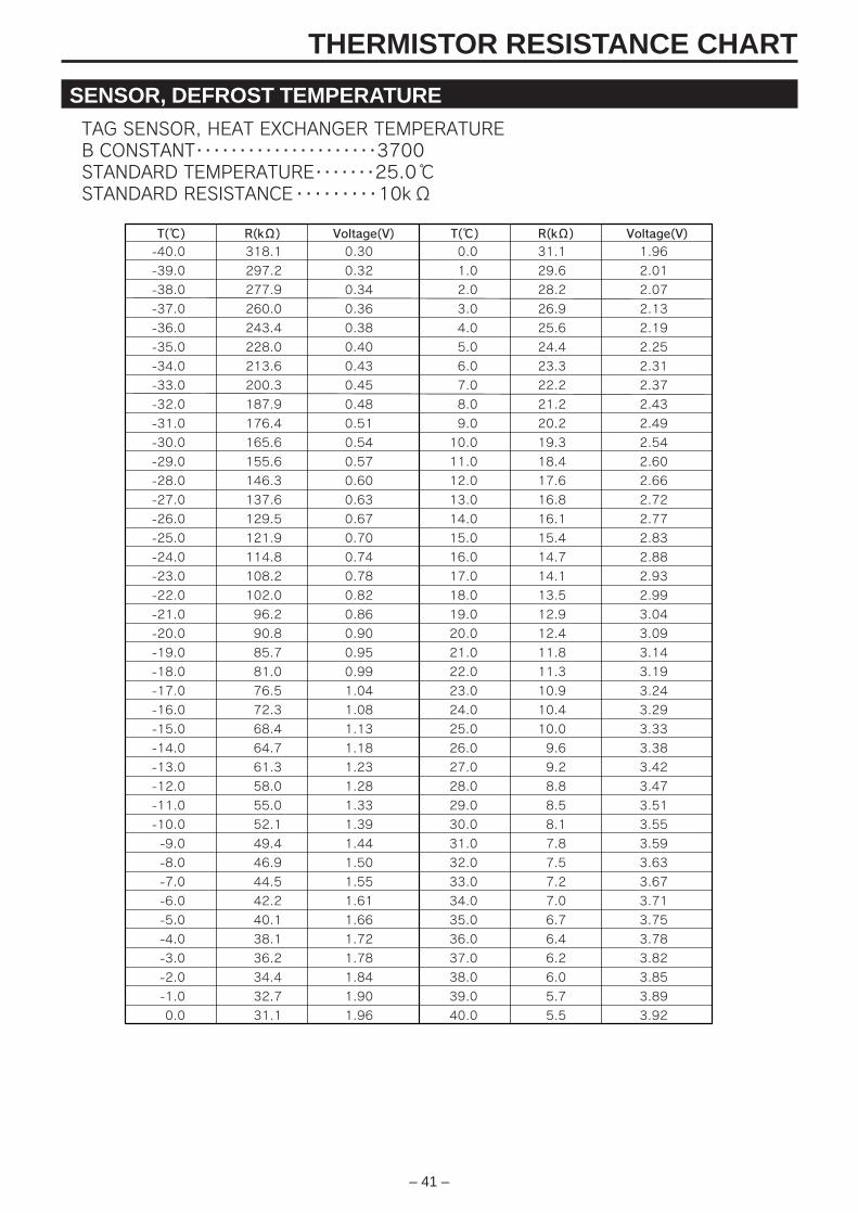
SENSOR, DEFROST TEMPERATURE
THERMISTOR RESISTANCE CHART
TAG SENSOR, HEAT EXCHANGER TEMPERATUREB CONSTANT・・・・・・・・・・・・・・・・・・・・・3700STANDARD TEMPERATURE・・・・・・・25.0℃STANDARD RESISTANCE・・・・・・・・・10kΩ
Voltage(V)-40.0 318.1 0.30 0.0 31.1 1.96
-39.0 297.2 0.32 1.0 29.6 2.01
-38.0 277.9 0.34 2.0 28.2 2.07
-37.0 260.0 0.36 3.0 26.9 2.13
-36.0 243.4 0.38 4.0 25.6 2.19
-35.0 228.0 0.40 5.0 24.4 2.25
-34.0 213.6 0.43 6.0 23.3 2.31
-33.0 200.3 0.45 7.0 22.2 2.37
-32.0 187.9 0.48 8.0 21.2 2.43
-31.0 176.4 0.51 9.0 20.2 2.49
-30.0 165.6 0.54 10.0 19.3 2.54
-29.0 155.6 0.57 11.0 18.4 2.60
-28.0 146.3 0.60 12.0 17.6 2.66
-27.0 137.6 0.63 13.0 16.8 2.72
-26.0 129.5 0.67 14.0 16.1 2.77
-25.0 121.9 0.70 15.0 15.4 2.83
-24.0 114.8 0.74 16.0 14.7 2.88
-23.0 108.2 0.78 17.0 14.1 2.93
-22.0 102.0 0.82 18.0 13.5 2.99
-21.0 96.2 0.86 19.0 12.9 3.04
-20.0 90.8 0.90 20.0 12.4 3.09
-19.0 85.7 0.95 21.0 11.8 3.14
-18.0 81.0 0.99 22.0 11.3 3.19
-17.0 76.5 1.04 23.0 10.9 3.24
-16.0 72.3 1.08 24.0 10.4 3.29
-15.0 68.4 1.13 25.0 10.0 3.33
-14.0 64.7 1.18 26.0 9.6 3.38
-13.0 61.3 1.23 27.0 9.2 3.42
-12.0 58.0 1.28 28.0 8.8 3.47
-11.0 55.0 1.33 29.0 8.5 3.51
-10.0 52.1 1.39 30.0 8.1 3.55
-9.0 49.4 1.44 31.0 7.8 3.59
-8.0 46.9 1.50 32.0 7.5 3.63
-7.0 44.5 1.55 33.0 7.2 3.67
-6.0 42.2 1.61 34.0 7.0 3.71
-5.0 40.1 1.66 35.0 6.7 3.75
-4.0 38.1 1.72 36.0 6.4 3.78
-3.0 36.2 1.78 37.0 6.2 3.82
-2.0 34.4 1.84 38.0 6.0 3.85
-1.0 32.7 1.90 39.0 5.7 3.89
0.0 31.1 1.96 40.0 5.5 3.92
R(kΩ)T(℃)Voltage(V)R(kΩ)T(℃)
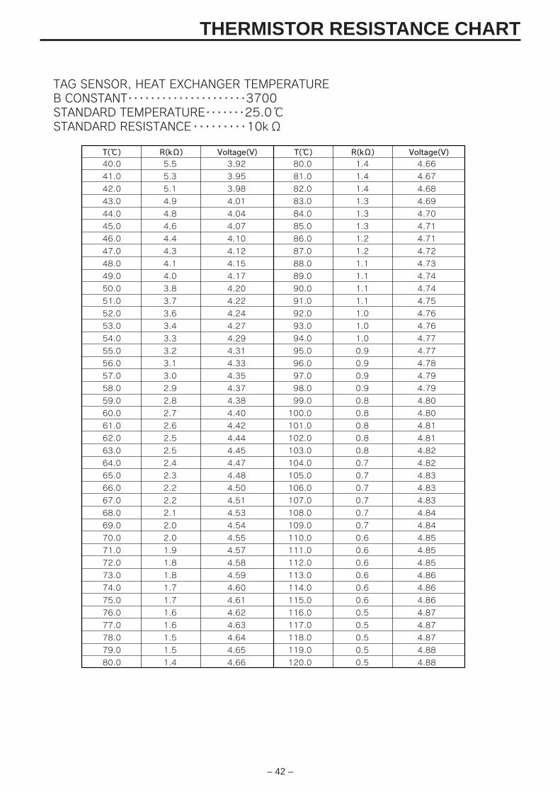
– 42 –
THERMISTOR RESISTANCE CHART
TAG SENSOR, HEAT EXCHANGER TEMPERATUREB CONSTANT・・・・・・・・・・・・・・・・・・・・・3700STANDARD TEMPERATURE・・・・・・・25.0℃STANDARD RESISTANCE・・・・・・・・・10kΩ
40.0 5.5 3.92 80.0 1.4 4.66
41.0 5.3 3.95 81.0 1.4 4.67
42.0 5.1 3.98 82.0 1.4 4.68
43.0 4.9 4.01 83.0 1.3 4.69
44.0 4.8 4.04 84.0 1.3 4.70
45.0 4.6 4.07 85.0 1.3 4.71
46.0 4.4 4.10 86.0 1.2 4.71
47.0 4.3 4.12 87.0 1.2 4.72
48.0 4.1 4.15 88.0 1.1 4.73
49.0 4.0 4.17 89.0 1.1 4.74
50.0 3.8 4.20 90.0 1.1 4.74
51.0 3.7 4.22 91.0 1.1 4.75
52.0 3.6 4.24 92.0 1.0 4.76
53.0 3.4 4.27 93.0 1.0 4.76
54.0 3.3 4.29 94.0 1.0 4.77
55.0 3.2 4.31 95.0 0.9 4.77
56.0 3.1 4.33 96.0 0.9 4.78
57.0 3.0 4.35 97.0 0.9 4.79
58.0 2.9 4.37 98.0 0.9 4.79
59.0 2.8 4.38 99.0 0.8 4.80
60.0 2.7 4.40 100.0 0.8 4.80
61.0 2.6 4.42 101.0 0.8 4.81
62.0 2.5 4.44 102.0 0.8 4.81
63.0 2.5 4.45 103.0 0.8 4.82
64.0 2.4 4.47 104.0 0.7 4.82
65.0 2.3 4.48 105.0 0.7 4.83
66.0 2.2 4.50 106.0 0.7 4.83
67.0 2.2 4.51 107.0 0.7 4.83
68.0 2.1 4.53 108.0 0.7 4.84
69.0 2.0 4.54 109.0 0.7 4.84
70.0 2.0 4.55 110.0 0.6 4.85
71.0 1.9 4.57 111.0 0.6 4.85
72.0 1.8 4.58 112.0 0.6 4.85
73.0 1.8 4.59 113.0 0.6 4.86
74.0 1.7 4.60 114.0 0.6 4.86
75.0 1.7 4.61 115.0 0.6 4.86
76.0 1.6 4.62 116.0 0.5 4.87
77.0 1.6 4.63 117.0 0.5 4.87
78.0 1.5 4.64 118.0 0.5 4.87
79.0 1.5 4.65 119.0 0.5 4.88
80.0 1.4 4.66 120.0 0.5 4.88
Voltage(V)R(kΩ)T(℃)Voltage(V)R(kΩ)T(℃)
– 47 –
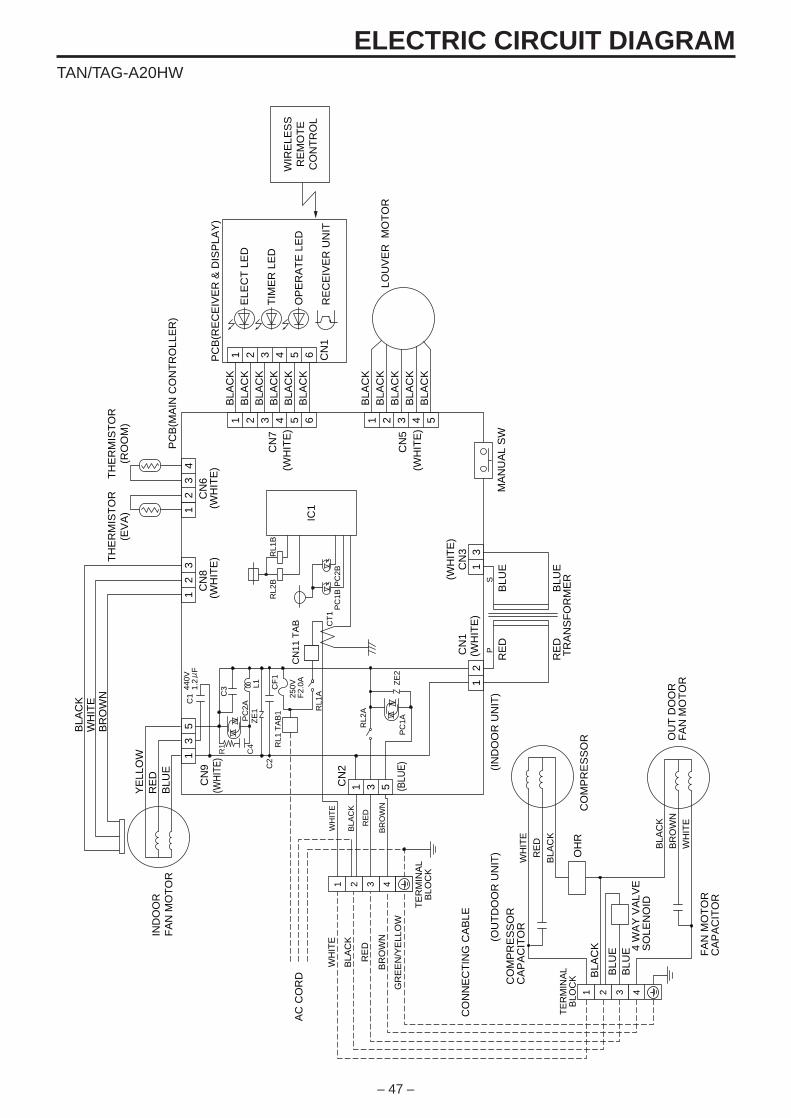
ELECTRIC CIRCUIT DIAGRAMTAN/TAG-A20HW
WIR
ELE
SS
�R
EM
OT
E�
CO
NT
RO
L
IND
OO
R�
FA
N M
OT
OR
YE
LLO
W�
RE
D�
BLU
E
BLA
CK
�W
HIT
E�
BR
OW
N
BLA
CK
�B
LAC
K�
BLA
CK
�B
LAC
K�
BLA
CK
�B
LAC
K
BLA
CK
�B
LAC
K�
BLA
CK
�B
LAC
K�
BLA
CK
PC
B(M
AIN
CO
NT
RO
LLE
R)
ELE
CT
LE
D
TIM
ER
LE
D
OP
ER
AT
E L
ED
RE
CE
IVE
R U
NIT
(IN
DO
OR
UN
IT)
(OU
TD
OO
R U
NIT
)
LOU
VE
R M
OT
OR
PC
B(R
EC
EIV
ER
& D
ISP
LAY
)
IC1
TH
ER
MIS
TO
R�
(EV
A)
TH
ER
MIS
TO
R�
(RO
OM
)
CT
1
RL2
B
PC
1BP
C2B
PS
RL1
B
CN
11 T
AB
1 2 3 4
TE
RM
INA
L�B
LOC
K
TE
RM
INA
L�B
LOC
K
WH
ITE
BLA
CK
RE
D
GR
EE
N/Y
ELL
OW
BR
OW
N
WH
ITE
BLA
CK
RE
D
BR
OW
N
PC
1A
RL1
A
RL1
TA
B1
RL2
A
1C
N8
CN
6
CN
7
CN
5
CN
1
CN
3C
N1
TR
AN
SF
OR
ME
R
MA
NU
AL
SW
CO
MP
RE
SS
OR O
UT
DO
OR
�F
AN
MO
TO
R
OH
R
4 W
AY
VA
LVE
�S
OLE
NO
ID
CO
MP
RE
SS
OR
�C
AP
AC
ITO
R
FA
N M
OT
OR
�C
AP
AC
ITO
R
CN
2
AC
CO
RD
CO
NN
EC
TIN
G C
AB
LE
1
3
3
5
5
11
1
1 2 3 4 5 6
1 2 3 4 5 6
1 2 3
3
4 5
2
2
31
23
4 (WH
ITE
)
(WH
ITE
)
(WH
ITE
)
(WH
ITE
)
(WH
ITE
)(W
HIT
E)
(BLU
E)
RE
D
WH
ITE
�
RE
D�
BLA
CK
BLA
CK
�B
RO
WN
�W
HIT
E
BLU
EB
LUE
BLA
CK
BLU
E
RE
DB
LUE
PC
2A
C3
C1
L1
CN
9(W
HIT
E)
250V
�F
2.0A
ZE
1
ZE
2
CF
1C
2
C4
R1
440V
�1.
2 F
1 2 3 4
– 48 –
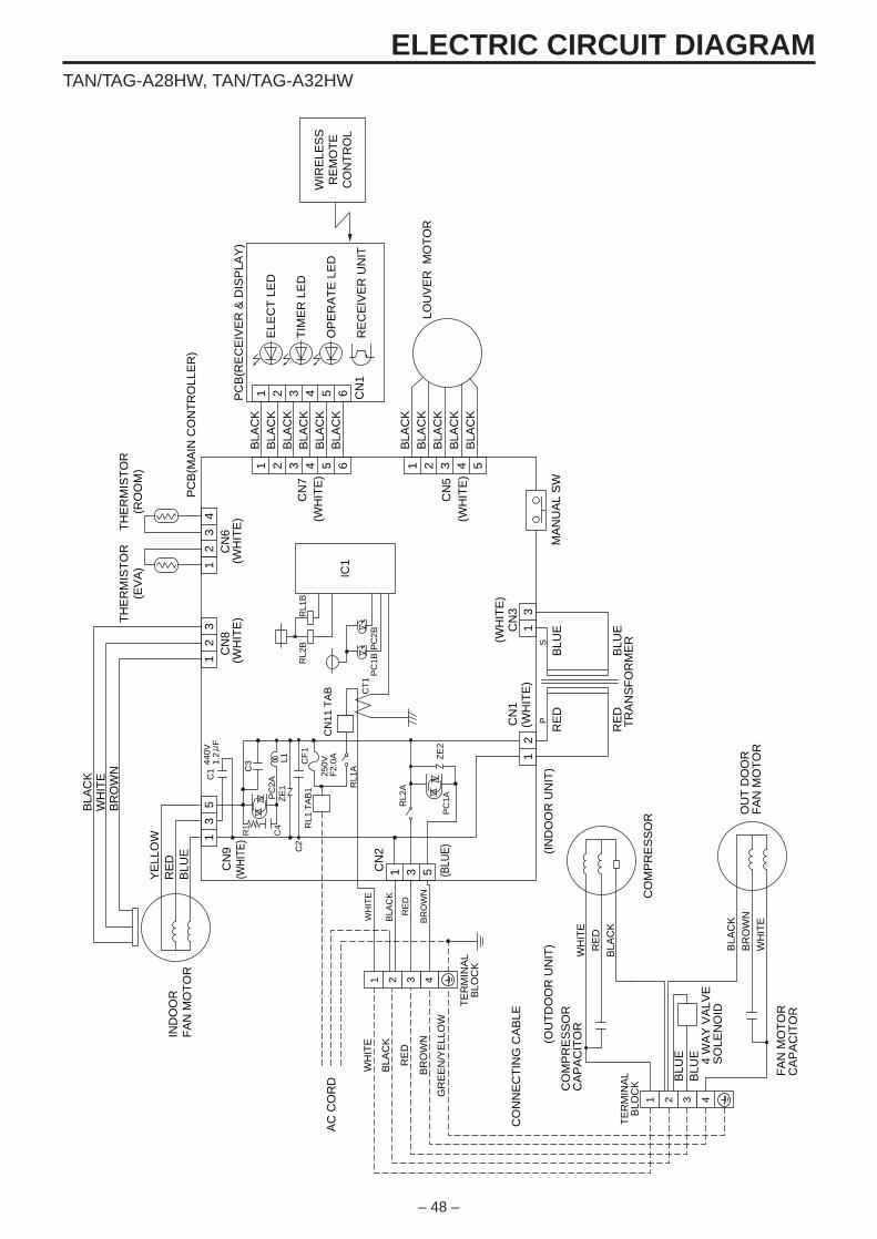
ELECTRIC CIRCUIT DIAGRAMTAN/TAG-A28HW, TAN/TAG-A32HW
WIR
ELE
SS
�R
EM
OT
E�
CO
NT
RO
L
IND
OO
R�
FA
N M
OT
OR
YE
LLO
W�
RE
D�
BLU
E
BLA
CK
�W
HIT
E�
BR
OW
N
BLA
CK
�B
LAC
K�
BLA
CK
�B
LAC
K�
BLA
CK
�B
LAC
K
BLA
CK
�B
LAC
K�
BLA
CK
�B
LAC
K�
BLA
CK
PC
B(M
AIN
CO
NT
RO
LLE
R)
ELE
CT
LE
D
TIM
ER
LE
D
OP
ER
AT
E L
ED
RE
CE
IVE
R U
NIT
(IN
DO
OR
UN
IT)
(OU
TD
OO
R U
NIT
)
LOU
VE
R M
OT
OR
PC
B(R
EC
EIV
ER
& D
ISP
LAY
)
IC1
TH
ER
MIS
TO
R�
(EV
A)
TH
ER
MIS
TO
R�
(RO
OM
)
CT
1
RL2
B
PC
1BP
C2B
PS
RL1
B
CN
11 T
AB
1 2 3 4
TE
RM
INA
L�B
LOC
K
TE
RM
INA
L�B
LOC
K
WH
ITE
BLA
CK
RE
D
GR
EE
N/Y
ELL
OW
BR
OW
N
WH
ITE
BLA
CK
RE
D
BR
OW
N
PC
1A
RL1
A
RL1
TA
B1
RL2
A
1C
N8
CN
6
CN
7
CN
5
CN
1
CN
3C
N1
TR
AN
SF
OR
ME
R
MA
NU
AL
SW
CO
MP
RE
SS
OR
OU
T D
OO
R�
FA
N M
OT
OR
4 W
AY
VA
LVE
�S
OLE
NO
ID
CO
MP
RE
SS
OR
�C
AP
AC
ITO
R
FA
N M
OT
OR
�C
AP
AC
ITO
R
CN
2
AC
CO
RD
CO
NN
EC
TIN
G C
AB
LE
1
3
3
5
5
11
1
1 2 3 4 5 6
1 2 3 4 5 6
1 2 3
3
4 5
2
2
31
23
4 (WH
ITE
)
(WH
ITE
)
(WH
ITE
)
(WH
ITE
)
(WH
ITE
)(W
HIT
E)
(BLU
E)
RE
D
WH
ITE
�
RE
D�
BLA
CK
BLA
CK
�B
RO
WN
�W
HIT
E
BLU
EB
LUE
BLU
E
RE
DB
LUE
PC
2A
C3
C1
L1
CN
9(W
HIT
E)
250V
�F
2.0A
ZE
1
ZE
2
CF
1C
2
C4
R1
440V
�1.
2 F
1 2 3 4
– 49 –
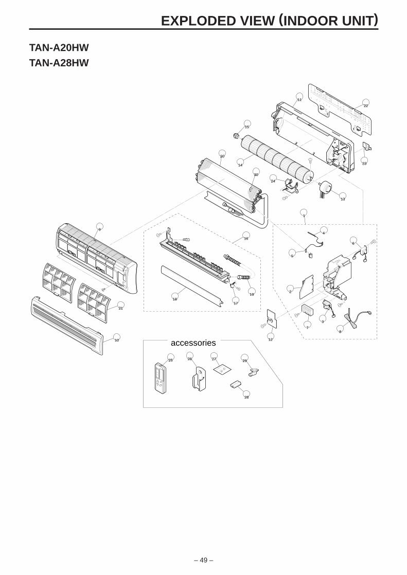
EXPLODED VIEW (INDOOR UNIT)
TAN-A20HWTAN-A28HW
28
26 29
5
19
1718
24
15
13
11
8
6
2
3
1
12
16
accessories
4
21
10
9
20
23
22
30
25 27
14
7
– 50 –
EXPLODED VIEW (INDOOR UNIT)
TAN-A32HW
5
4
15
11
13
14
22
20
19
17
18
24
30
7 8
6
2
3
1
12
16
2725 26
28
accessories
21
10
9
29
23
– 51 –
TAG-A20HW
EXPLODED VIEW (OUTDOOR UNIT)
2
5
1
6
7
11
13
9
21
19
18
20
15
16
12
14
3
4
8
17
22
2310
– 52 –
EXPLODED VIEW (OUTDOOR UNIT)
TAG-A28HW
16
1
5
6
15
11
8
10
19
3
14
13
18
9
7
12
20
4
2
4
21
22
17
– 53 –
TAG-A32HW
16
1
5
6
15
11
8
10
19
3
14
13
18
9
7
12
20
4
2
4
21
22
17
ISSUED JUL.2004
RA-20-[1]
Printed in Japan