TankInspect - CORDIScordis.europa.eu/docs/publications/1263/126376111-6_en.pdf · develop novel...
12
TankInspect/PR/TWI/CE/300806/1 Contract COOP-CT-2003-508486 COOP-CT-2003-508486 TankInspect Condition monitoring of large oil and chemical storage tanks using ultrasonic guided wave tomography without the need to empty and clean the tanks Horizontal Research Activities Involving SMEs Co-operative Research Publishable Activity Report Period covered: from 1 March 2004 to Aug 2006 Date of preparation: November 2006 Start date of project: 1 March 2004 Duration: 30 months Project co-ordinator: Dr Chris Edwards Project co-ordinator organisation: TWI Ltd Revision 1
Transcript of TankInspect - CORDIScordis.europa.eu/docs/publications/1263/126376111-6_en.pdf · develop novel...

TankInspect/PR/TWI/CE/300806/1 Contract COOP-CT-2003-508486
COOP-CT-2003-508486
TankInspect
Condition monitoring of large oil and chemical storage tanks using ultrasonic guided wave tomography without the need to empty and clean the tanks
Horizontal Research Activities Involving SMEs
Co-operative Research
Publishable Activity Report Period covered: from 1 March 2004 to Aug 2006 Date of preparation: November 2006 Start date of project: 1 March 2004 Duration: 30 months Project co-ordinator: Dr Chris Edwards Project co-ordinator organisation: TWI Ltd Revision 1

TankInspect/PR/TWI/CE/300806/1 Contract COOP-CT-2003-508486
PUBLISHABLE FINAL ACTIVITY REPORT
Full title: Condition monitoring of large oil and chemical storage tanks using ultrasonic guided wave tomography without the need to empty and clean the tank
Acronym: TankInspect
Date of Preparation: August 2006
Type of Instrument: Co-operative Research project
Co-ordinator: RTD 1 TWI UK
List of participants: SME 1 Spree Engineering Ltd UK SME 2 Tecnitest Spain SME 3 Isotest Engineering Ltd Italy SME 4 Coaxial Power Systems Ltd UK OTH 1 Royal Vopak Holland OTH 2 Kaneb Terminals Ltd UK OTH 3 Total France
RTD 2 Kaunas University of Technology Lithuania
RTD 3 Kingston Computer Consultancy Ltd UK
Reporting Period Start and end date
June 2005 – August 2006
Document Version 01
Project Co-ordinator:
Dr Chris Edwards TWI Ltd Email: [email protected] Fax +44 (0) 1639 86 46 79

TankInspect/PR/TWI/CE/300806/1 Contract COOP-CT-2003-508486
TABLE OF CONTENTS 1. Summary .......................................................................................................................................... 1 2. Project Objectives and Major Achievements................................................................................ 2
2.1. General Project Objectives 2 2.2. Project Workpackages 2 2.3. Project Achievements 2 2.3.1. Test tanks 2 2.3.2. Numerical Modelling. 3 2.3.3. Tomographic Reconstruction. 5 2.3.4. Prototype Hard and Software 8
3. Dissemination and Use .................................................................................................................... 8

TankInspect/PR/TWI/CE/300806/1 1 Contract COOP-CT-2003-508486
1. SUMMARY
The results of the TankInspect project have proved the principle of using ultrasonic guided waves to inspect the floor plates of large storage tanks. The waves are generated and detected by transducers coupled to the edge of the annular plate. Many measurements are carried out in different directions across the tank. The data is processed using tomographic reconstruction techniques to give a colour-coded map of the tank floor. Areas of high attenuation indicate potential areas of corrosion. The work carried out under the TankInspect project demonstrated that inspection of tank floor plates from the annular plate without emptying a tank is feasible. The major problem encountered was achieving consistent ultrasonic coupling to the edge of the storage tank rim.

TankInspect/PR/TWI/CE/300806/1 2 Contract COOP-CT-2003-508486
2. PROJECT OBJECTIVES AND MAJOR ACHIEVEMENTS
2.1. GENERAL PROJECT OBJECTIVES
Large above ground storage tanks filled with hazardous liquids such as oil, oil-derived products, chemicals and food processing liquids are in widespread use in Europe and throughout the rest of the world. The TankInspect project aimed to develop a condition monitoring system for large storage tanks based on ultrasonic guided wave tomography. To overcome the drawbacks of current inspection practices, the consortium proposed to develop novel Long Range Ultrasonic Testing (LRUT) techniques for monitoring corrosion in tank floor plates, without the need to empty and clean the tank. The advantage of the proposed method was the ability to detect corrosion on tank floors without the need to empty and clean the tank and without the need for operator entry inside the tank. 2.2. PROJECT WORKPACKAGES
The project was divided into several workpackages: • A survey was undertaken of the problem to identify what hard and software capabilities
would be needed. • Representative defect samples were acquired and small scale model tanks for laboratory
development work were manufactured. • Numerical modelling studies were carried out of guided wave propagation in lap-welded
plates to identify the best wave modes to use. • Novel guided wave transducers were studied to generate these wave modes from the
outside of a tank • Signal processing routines were developed to improve the signal to noise ratios • Tomographic reconstruction routines were developed to produce maps of tank floor
attenuation. • A prototype multi-channel guided wave ultrasonic pulser-receiver and control and data
collection software was developed and field measurements were carried out on storage tanks.
2.3. PROJECT ACHIEVEMENTS
2.3.1. Test tanks
Several test tanks were constructed, these were used for experimental verification of the numerical modelling. The tanks sat on a bed of wet sand and could be filled with water to simulate realistic conditions.

TankInspect/PR/TWI/CE/300806/1 3 Contract COOP-CT-2003-508486
Figure 1: Test Tank with pumping system to control fill level. 2.3.2. Numerical Modelling.
The tank floors are fabricated from steel plates (usually 6mm thick) with lap weld joints. The tanks often sit on a bed of tar sand, and contain various liquids such as diesel.
Figure 2 Model of Tank Floor. Numerical modelling was used to study wave propagation through lap welded plates including attenuation losses into the liquid (diesel) and the tar sand. The results showed that the fast (non-dispersive) S0 wave was best suited as it has low attenuation. The losses into the diesel and tar sand are comparatively low with the main
Diesel
Wet sand Overlap 80 mm
380 mm
500 mm 600 mm
100 mm 500 mm
Source
Rc1 Rc2
Rc3 Rc4
Weld

TankInspect/PR/TWI/CE/300806/1 4 Contract COOP-CT-2003-508486
attenuation being due to reflection and mode conversion in the lap welds. The typical loss in a single lap weld is 8 dB. Further modelling showed that the losses on passing through multiple lap welds were additive and this was confirmed by experiment.
Figure 3 Low order Lamb waves calculated for the 8mm thick tank The dispersion curves shown in figure 3 show that the S0 mode has almost constant velocity below 50 Hz. Two types of boundary conditions between the steel plate and the sand were modelled:
• Perfect bonding – plate rigidly coupled to the sand • Slip bonding- plate allowed to slide over the sand.
Figure 4 Attenuation calculated for perfect bonding (red) and slip bonding (blue) If the plate was rigidly coupled to the sand the attenuation losses would be extremely high (~10dB/m) but experimental measurements with the test tanks confirmed the slip bonding
0 20 40 60 80 f,kHz 0
5
10
α, dB/m
6
5
4
3
2
1
0
velo
city
mm
µ−1
0.50.40.30.20.10.0Frequency MHz
A0
S0 A1
TankInspect/PR/TWI/CE/300806/1 5 Contract COOP-CT-2003-508486
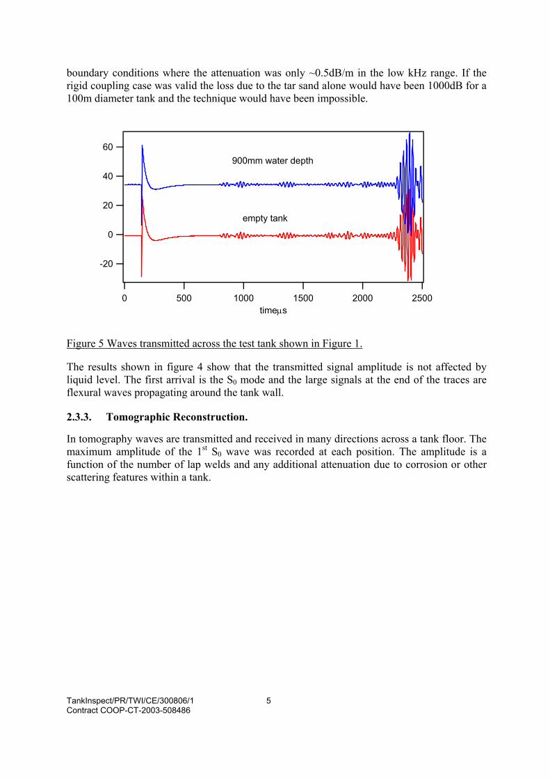
boundary conditions where the attenuation was only ~0.5dB/m in the low kHz range. If the rigid coupling case was valid the loss due to the tar sand alone would have been 1000dB for a 100m diameter tank and the technique would have been impossible.
Figure 5 Waves transmitted across the test tank shown in Figure 1. The results shown in figure 4 show that the transmitted signal amplitude is not affected by liquid level. The first arrival is the S0 mode and the large signals at the end of the traces are flexural waves propagating around the tank wall. 2.3.3. Tomographic Reconstruction.
In tomography waves are transmitted and received in many directions across a tank floor. The maximum amplitude of the 1st S0 wave was recorded at each position. The amplitude is a function of the number of lap welds and any additional attenuation due to corrosion or other scattering features within a tank.
60
40
20
0
-20
25002000150010005000timeµs
900mm water depth
empty tank

TankInspect/PR/TWI/CE/300806/1 6 Contract COOP-CT-2003-508486
Figure 6. The maximum amplitude of the S0 wave is recorded at each position.
A time window was automatically positioned over the 1st arrival and its amplitude recorded for use in the tomographic reconstruction, see figure 5.
` Figure 7. Backprojection of the single projection in the virtual tank floor plane
Figure 6 illustrates the backprojection used for the reconstruction from a single generation point. Many such measurements are taken in different locations around the tank and overlapped to produce the final reconstruction.
1 1.5 2 2.5 3 3.5
-0.1
-0.05
0
0.05
0.1
u(t)
Umax
t, ms
-4 -2 0 2 4 -4-2
0
24
0
0.5
1
1.5 P(x,y)
x
y
axyk1 k2
The virtual tank floor plane
ak1ak2

TankInspect/PR/TWI/CE/300806/1 7 Contract COOP-CT-2003-508486
Figure 8. Overlapping of the backprojected projections on the virtual tank floor plane
Figure 9.Reconstructed distribution of attenuation of S0 waves propagating in the tank floor. The red areas correspond to the areas with an essentially higher attenuation. The grey lines show the positions of welds.
x, m
y, m
Σ
Virtual tank floor plane
Backprojected projections

TankInspect/PR/TWI/CE/300806/1 8 Contract COOP-CT-2003-508486
2.3.4. Prototype Hard and Software
A 24 channel pulser receiver based on Teletest® electronic components was constructed, as the system is modular the number of channel could be increased by using more cards. Dedicated Man-Machine Interface software was written to control the prototype TankInspect instrument and record: • Tank parameters • Client details • Transducer locations and collected data A screenshot of the software is shown in figure 9.
Figure 10 TankInspect software showing transducer location and collected data. 3. DISSEMINATION AND USE
The completed TankInspect system has the following functions: • Prototype multi-channel long-range ultrasonic pulser receiver suitable for the inspection of
storage tanks. • The TankInspect man-machine interface for controlling the ultrasonic pulser receiver and
storing data tank details and transducer locations. • A set of post processing routines for tomographic reconstruction capable of producing an
attenuation map of a tank floor Interested parties should contact:

TankInspect/PR/TWI/CE/300806/1 9 Contract COOP-CT-2003-508486
Name: Chris Edwards Address: TWI Wales, Heol Cefn Gwrgan, Margam , Port Talbot e-mail: [email protected]