Tank & Cylinder Fittings - SeekPartfile.seekpart.com/keywordpdf/2011/3/28/2011328184744421.pdf ·...
12
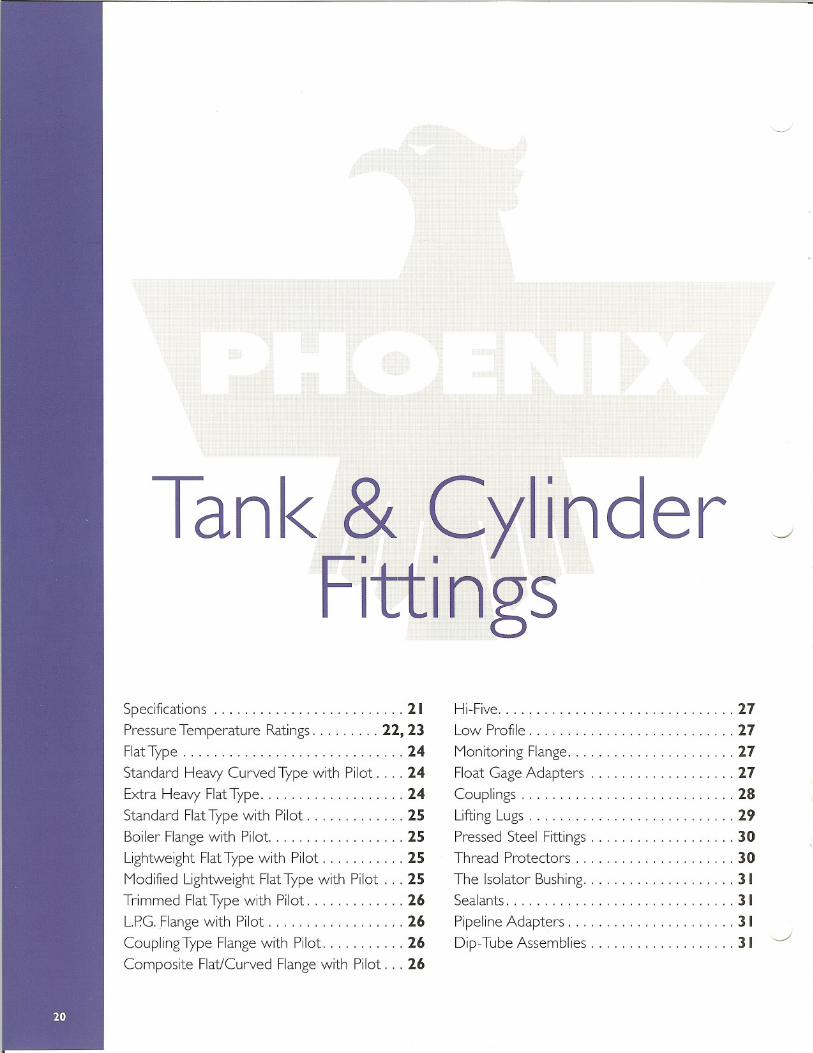
Tank& Cylinder Fittings Specifications ......................... 2. Pressure Temperature Ratings......... 22, 23 FlatType ............................. 24 Standard Heavy Curved Type with Pilot.... 24 Extra Heavy FlatType................... 24 Standard FlatTypewith Pilot............. 25 Boiler Flange with Pilot.................. 25 Lightweight FlatType with Pilot. .......... 25 ModifiedLightweightFlatTypewith Pilot ... 25 Trimmed FlatType with Pilot............. 26 L.P.G.Flange with Pilot.................. 26 Coupling Type Flange with Pilot........... 26 Composite Flat/Curved Flange with Pilot. . . 26 Hi-Five............................... 27 Low Profile........................... 27 MonitoringFlange...................... 27 Float Gage Adapters. .................. 27 Couplings ............................ 28 Lifting Lugs. .......................... 29 Pressed Steel Fittings ................... 30 Thread Protectors ..................... 30 The Isolator Bushing.................... 31 Sealants..................... . ........ 3. PipelineAdapters. ..................... 3. Dip-Tube Assemblies. .................. 31
Transcript of Tank & Cylinder Fittings - SeekPartfile.seekpart.com/keywordpdf/2011/3/28/2011328184744421.pdf ·...
Tank& CylinderFittings
Specifications . . . . . . . . . . . . . . . . . . . . . . . . . 2.Pressure Temperature Ratings. . . . . . . . . 22, 23
FlatType . . . . . . . . . . . . . . . . . . . . . . . . . . . . . 24
Standard Heavy Curved Type with Pilot. . . . 24Extra Heavy FlatType. . . . . . . . . . . . . . . . . . . 24Standard FlatTypewith Pilot. . . . . . . . . . . . . 25Boiler Flange with Pilot. . . . . . . . . . . . . . . . . . 25Lightweight FlatType with Pilot. . . . . . . . . . . 25
ModifiedLightweightFlatType with Pilot . . . 25Trimmed FlatType with Pilot. . . . . . . . . . . . . 26L.P.G.Flange with Pilot. . . . . . . . . . . . . . . . . . 26Coupling Type Flange with Pilot. . . . . . . . . . . 26
Composite Flat/Curved Flange with Pilot. . . 26
Hi-Five. . . . . . . . . . . . . . . . . . . . . . . . . . . . . . . 27
Low Profile. . . . . . . . . . . . . . . . . . . . . . . . . . . 27
MonitoringFlange.. . . . . . . . . . . . . . . . . . . . . 27Float Gage Adapters. . . . . . . . . . . . . . . . . . . 27Couplings . . . . . . . . . . . . . . . . . . . . . . . . . . . . 28Lifting Lugs. . . . . . . . . . . . . . . . . . . . . . . . . . . 29
Pressed Steel Fittings . . . . . . . . . . . . . . . . . . . 30Thread Protectors . . . . . . . . . . . . . . . . . . . . . 30
The Isolator Bushing.. . . . . . . . . . . . . . . . . . . 31Sealants. . . . . . . . . . . . . . . . . . . . . . . . . . . . . . 3 .
PipelineAdapters. . . . . . . . . . . . . . . . . . . . . . 3 .Dip-TubeAssemblies.. . . . . . . . . . . . . . . . ..31
Pipe size:Pipe size:Pipe size:
I/S"to (112"-2" to 4"5" to 8"
:!: 1/32"+ 3/64" _1/32"+ 1/16" _1/32"
Pipe size:Pipe size:Pipe size:
I/S"to 21/2"-3" to 31/2"4" to 8"
:!: 1/32"+ 3/64" _1/32"+ 1/16" _1/32"
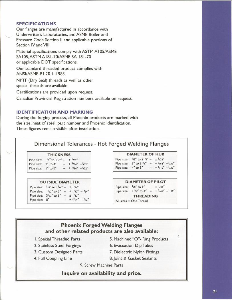
SPECIFICATIONS
Our flangesare manufactured in accordance withUnderwriter's Laboratories, and ASMEBoiler andPressure Code Section IIand applicable portions ofSection IV and VIII.
Material specifications comply with ASTM A I05/ ASMESA IOS,ASTM A 181-70/ASME SA 181-70
or applicable DOT specifications.
Our standard threaded product complies withANSI/ASMEB1.20.1-1983.
NPTF (Dry Seal) threads as well as otherspecial threads are available.
Certifications are provided upon request.
Canadian ProvincialRegistration numbers availableon request.
IDENTIFICATION AND MARKING
During the forging process, all Phoenix products are marked withthe size, heat of steel, part number and Phoenix identification.These figures remain visible after installation.
Dimensional Tolerances - Hot Forged Welding Flanges
THICKNESS DIAMETER OF HUB
OUTSIDE DIAMETER DIAMETER OF PILOT
P~*~P~*~P~*~P~*~
I/S"to 11/4"-11/2"to 3"31/2"to 6"8"
:!: 1/64"+ 1/32" _1/64":I: 1/32"+ 3/64" _1/32"
Pipe size: I/S"to I" - :I: 1/32"Pipe size: 11/4" to 4" - + 3/64" _1/32"
THREADING
All sizes :I: One Thread
Phoenix Forged Welding Flangesand other related products are also available:
I. SpecialThreaded Parts 5. Machined"0"- RingProducts
2. Stainless Steel Forgings 6. Evacuation DipTubes
3. Custom Designed Parts 7. Dielectric Nylon Fittings
4. FullCoupling Line 8.Joint & Gasket Sealants9. Screw Machine Parts
Inquire on availability and price.

AIISYS 5.4APR 21 1998
13:50:19BODALSOLUTIOIJSTI!P=lSUB =1TIME=1
sIIrr (AVG!
PowerGrapb.1.csI!rACBT=l
AVRES=Mat
DMX =.010844
SM!l =16278
SMX =37713
== ~OOOD 10000E:J 15000I!!III 20000~ 25000D 30000o 35000_ 40000
45000
@ I 998 THE PHOENIX FORGE GROUP
AllSIS 5.4APR 21 199813:33:19gODAL Sar.DTIOJISTEP=lSUB =1TIMH=lSIIIT (AVG)
PowerGraph1.csBrACRT=lAVREs=MatDMX=.010196SM!l =2050SMX =40404
== ~OOOGJ 10000L:I 15000_ 20000!i;;iI 25000D 30000g 35000_ 4000045000
coup_Dt: 1.5" half-coupling - 547 ps:lg
9
8
AIISYS S.4APR 21 199813:52.13NODALSOLUTIONSTEFlSUB=1TIME=1SIIIT (AVG!
PowerGraph1.cs!lACBT=lAVREs=-:MatDMX=.010006
SM!l=1023SMX =41121
== ~OOOo 10000E:::I 15000I!!III 20000Ii:J 25000D 30000D 35000_ 4000045000
10
AIlSYS 5.4APR 21 1998
13:32:20
IJODAL SOLUTIOIl
STBP=l
SUB=1TIME=1
SIIIT (AVG!
PowerGraphicsBrACBT=l
AVREs=MatDMX =.010047
SM!l=1158SMX =38947
= ~OOOD 10000~ 15000_ 20000~ 25000D 30000IGJ 35000_ 4000045000
14
ph457_01: PhoenixForgeUttU1g 1.5"-457: 547 p.ig
97058: ph153_01: Phoenix lorge f1.tting2"-153: 547 p!!Jig
AIISIS 5.4APR 21 1998
13:34:18
)lODAL SOLUTIO.
STlP=l
SUB=1TIMB=l
SIIIT (AVGI
PowerGraph1.csSrACBT=l
AVRES=Mat
DMX =.01025
SM!l = 1999
SMX =39810
== ~OOOD 10000EJ 15000_ 2000011II 25000r;;;;;] 300006:J 35000_ 4000045000
,1
t-
-
-
hole01. 2" WPS hole (2.375"ODI - 547 pdq
1
---
-1 II') I J I- I TT [rr-t-t-
ffr1Tf[1I , I 1 1f r r J Ir r T'
pbl08 01: Phoenix Forge Utting 2".108: 547 p.ig
... I\
I\\\.13\)(\.
2 J/ "-- -
I
11
. - .-ph397 01: Phoenix lorgefJ.tting 1.5"-397: 547 psig
ARSYS 5.4APR 21 199813:36,50JlODALSOLUTIOJlSTI!P=lSUB =1TIMB=1
SIlT (AVG)PowerGraph1.c.!JBFACET=lAVRHS=MatDMX=.010107SM1I=764.477""" =40036
= ~OOOD 100001:1 15000_ 20000
E:I 25000D 30000D 35000_ 4000045000
20
ph707_D1: Phoenix porgef.1tt1.ng' 1.5"-707: 547 p.!J1g
ARSYS 5.4APR 21 199813 :38: 20
NODALSOLUTIONSTeP=lSUB =1TIMB=1SIlT (AVG)PowerGraph.1c8SFAC!!T=1AVRB5=MatDMX=.010232SMII =407.927""" =39984
:= ~oooo 10000~ 15000_ 20000~ 25000D 30000q;;) 35000_ 40000
45000
23
ph957_01: PhocJUx Forge f.1tting1.5"-957: 547 p:l19
Phoenix Pressure Vessel Fittings -Pressure Temperature Ratings BasisThe finite element analysissummarized in the above figures were performed to confirm the strength-equivalence
between a standard Phoenix Forge Group ASMEB16.11,Class 3000 threaded coupling and threaded fittings,when welded toa pressure vessel in accordance with SectionVIII,Division I of the ASMEBoiler and Pressure Vessel Code.The design temperature and other service conditions for all welding fittings are limited by various construction codes.Within these limits,The Phoenix Forge Group certifies its welding fittings identified as such, as Manufacturer's Standard perASME SectionVIII,Division I, paragraph UG-II (a) (I).
When identifiedwith a 3000 or a 3M the maximum allowable pressure for a fitting is that computed for Schedule 160straight seamless pipe of equivalent material, as done in ASMEB36.11. The wall thickness used in such computation shall bethat tabulated inASMEB36.1OMfor the fitting nominal pipe size and schedule 160,reduced by applicable manufacturing tol-erances and other allowances (e.g.,threaded allowances). Any corrosion allowance and any variation in allowable stress dueto temperature shall be applied to the pipe and fitting alike.
Note that the pressure-temperature ratings obtained in this manner are for the fitting,because the fitting to pipe orvessel attachment welds are governed by design codes such as ASMESectionVIII,Divisional I, paragraph UW-16,which mayimpose more restrictive pressure-temperature limits.
NOTICEIt should be noted that this study is supportive only of The Phoenix Forge Group Pressure Vessel Fittingsproven
designs. No consent is given to use Phoenix Pressure Vessel Fittingsproof of test or mathematical calculation to supportother manufacturer's products which may be similar to Phoenix designs. Furthermore, it is cautioned that the use of thesetests or calculations to support other manufacturer's products may be invalidbecause of differences in materials, fabricationprocesses or dimensions.
@ 1998THE PHOENIX FORGE GROUP
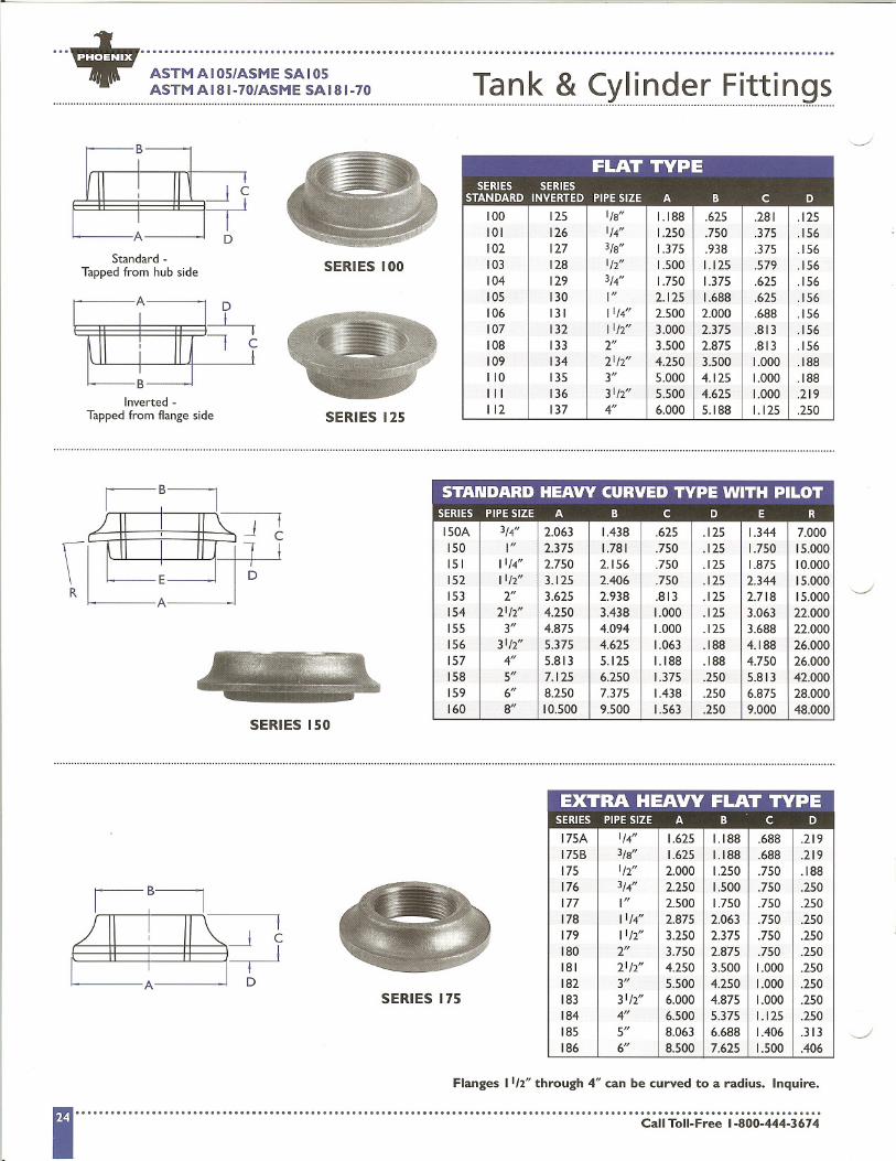
...+ ....................................................................................................................... .ASTMAI05/ASME SAI05 T k & C
.
I
"
d r F"
ltt"
1 ngsASTMAI81-70/ASMESAI81-70 Ian Y In e"....................................................................................................................
B
Standard-Tapped from hub side
BInverted -
Tapped from flange side
SERIES 100
SERIES 125
B
SERIES 150
f--1 c~
DSERIES 175
Flanges 11/2"through 4" can be curved to a radius. Inquire.
11II c:;;iii-~i.;;;;~.i:.00:4:;4:3.7"
FLAT TYPESERIES SERIES
STANDARD INVERTED PIPESIZE A B C D
100 125 I/a" 1.188 .625 .281 .125101 126 1/4" 1.250 .750 .375 .156102 127 3/a" 1.375 .938 .375 .156103 128 1/2" 1.500 1.125 .579 .156104 129 3/4" 1.750 1.375 .625 .156105 130 I" 2.125 1.688 .625 .156106 131 11/4" 2.500 2.000 .688 .156107 132 1112" 3.000 2.375 .813 .156108 133 2" 3.500 2.875 .813 .156109 134 2112" 4.250 3.500 1.000 .188110 135 3" 5.000 4.125 1.000 .188III 136 31/2" 5.500 4.625 1.000 .219112 137 4" 6.000 5.188 1.125 .250
STANDARD HEAVY CURVED TYPE WITH PILOTSERIES PIPESIZE A B C D E R
150A 3/4" 2.063 1.438 .625 .125 1.344 7.000150 I" 2.375 1.781 .750 .125 1.750 15.000151 11/4" 2.750 2.156 .750 .125 1.875 10.000152 11/2" 3.125 2.406 .750 .125 2.344 15.000153 2" 3.625 2.938 .813 .125 2.718 15.000154 2112" 4.250 3.438 1.000 .125 3.063 22.000155 3" 4.875 4.094 1.000 .125 3.688 22.000156 31/2" 5.375 4.625 1.063 .188 4.188 26.000157 4" 5.813 5.125 1.188 .188 4.750 26.000158 5" 7.125 6.250 1.375 .250 5.813 42.000159 6" 8.250 7.375 1.438 .250 6.875 28.000160 8" 10.500 9.500 1.563 .250 9.000 48.000
EXTRA HEAVY FLAT TYPE- - --SERIES PIPESIZE A B C D
175A 1/4" 1.625 1.188 .688 .219175B 3/a" 1.625 1.188 .688 .219175 1/2" 2.000 1.250 .750 .188176 3/4" 2.250 1.500 .750 .250177 I" 2.500 1.750 .750 .250178 11/4" 2.875 2.063 .750 .250179 1112" 3.250 2.375 .750 .250180 2" 3.750 2.875 .750 .250181 21/2" 4.250 3.500 1.000 .250182 3" 5.500 4.250 1.000 .250183 31/2" 6.000 4.875 1.000 .250184 4" 6.500 5.375 1.125 .250185 5" 8.063 6.688 1.406 .313186 6" 8.500 7.625 1.500 .406
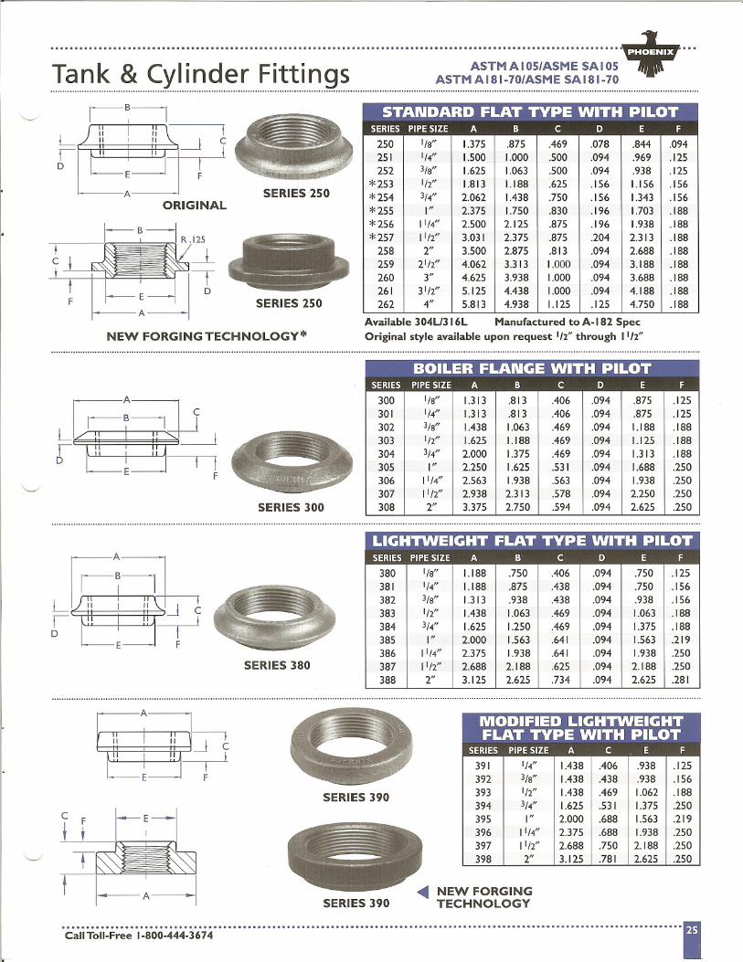
+.... .T k & C 1
8
d F8
tt 8 ASTMAI05/ASME SAI05
.an Y In er lings ASTMAI81-70/ASMESAI81-70
F~D t IE F
SERIES 300
SERIES 380
A
II I II , :-I--1 cr
F
SERIES 390
SERIES 390
.C:~iii~I;:F;;;;i:.iio:444:j;;74 11II
'-....../
LI 250 I/a" 1.375 .875 .469 .078 .844 .094
l: I I C.... ...... ..251 1/4" 1.500 1.000 .500 .094 .969 .125252 3/a" 1.625 1.063 .500 .094 .938 .125
*253 1/2" 1.813 1.188 .625 .156 1.156 .156A I SERIES 250
1*2543/4" 2.062 1.438 .750 .156 1.343 .156
ORIGINAL *255 I" 2.375 I.750 .830 .196 1.703 .188*256 11/4" 2.500 2.125 .875 .196 1.938 .188*257 11/2" 3.031 2.375 .875 .204 2.313 .188
258 2" 3.500 2.875 .813 .094 2.688 .188259 21/2" 4.062 3.313 1.000 .094 3.188 .188260 3" 4.625 3.938 1.000 .094 3.688 .188261 31/2" 5.125 4.438 1.000 .094 4.188 .188
SERIES 250 I 262 4" 5.813 4.938 1.125 .125 4.750 .188
Available 304U316L Manufactured to A-182 SpecNEW FORGING TECHNOLOGY* Original style available upon request 1/2"through 1'/2"
BOILER FLANGE WITH PILOT___.________________n.____n_n____.n____..._..._...n_.._.._....._._...__......_.....__.___..__.._...._.n__........._...._......_.____nn__
SERIES PIPESIZE A B C D E F
300 I/a" 1.313 .813 .406 .094 .875 .125301 1/4" 1.313 .813 .406 .094 .875 .125302 3/a" 1.438 1.063 .469 .094 1.188 .188303 1/2" 1.625 1.188 .469 .094 1.125 .188304 3/4" 2.000 1.375 .469 .094 1.313 .188305 I" 2.250 1.625 .531 .094 1.688 .250306 11/4" 2.563 1.938 .563 .094 1.938 .250307 11/2" 2.938 2.313 .578 .094 2.250 .250308 2" 3.375 2.750 .594 .094 2.625 .250
LIGHTWEIGHT FLAT TYPE WITH PILOT--
SERIES PIPESIZE A B C D E F
380 I/a" 1.188 .750 .406 .094 .750 .125381 1/4" 1.188 .875 .438 .094 .750 .156382 3/a" 1.313 .938 .438 .094 .938 .156383 1/2" 1.438 1.063 .469 .094 1.063 .188384 3/4" 1.625 1.250 .469 .094 1.375 .188385 I" 2.000 1.563 .641 .094 1.563 .219386 11/4" 2.375 1.938 .641 .094 1.938 .250387 1112" 2.688 2.188 .625 .094 2.188 .250388 2" 3.125 2.625 .734 .094 2.625 .281
391 1/4" 1.438 .406 .938 .125392 3/a" 1.438 .438 .938 .156393 1/2" 1.438 .469 1.062 .188394 3/4" 1.625 .531 1.375 .250395 I" 2.000 .688 1.563 .219396 11/4" 2.375 .688 1.938 .250397 11/2" 2.688 .750 2.188 .250398 2" 3.125 .781 2.625 .250
NEW FORGINGTECHNOLOGY
...+ ....................................................................................................................... .ASTM AI05/ASME SAI05 T k & C I
.d F
.tt
.ASTMAI81-70/ASMESAI81-70 Ian Y In er lings
IB~I" I '"
L
SERIES 450
SERIES 458~ NEW FORGING
TECHNOLOGY
A
SERIES 500 ~ NEW FORGING TECHNOLOGY
liPSERIES 700 D
A
\ ESERIES700-R
SERIES 700
A
R
E
A
E
c
SERIES 950
SERIES 958 R
Sizes over 3/4" -Inquire.
Available on inquiry in most styles and sizes.Special machined chamfer to suit your requirements.
1iII ;:;;,.,;~.:;;~;'j:.0Q:4;;j;]6':.i
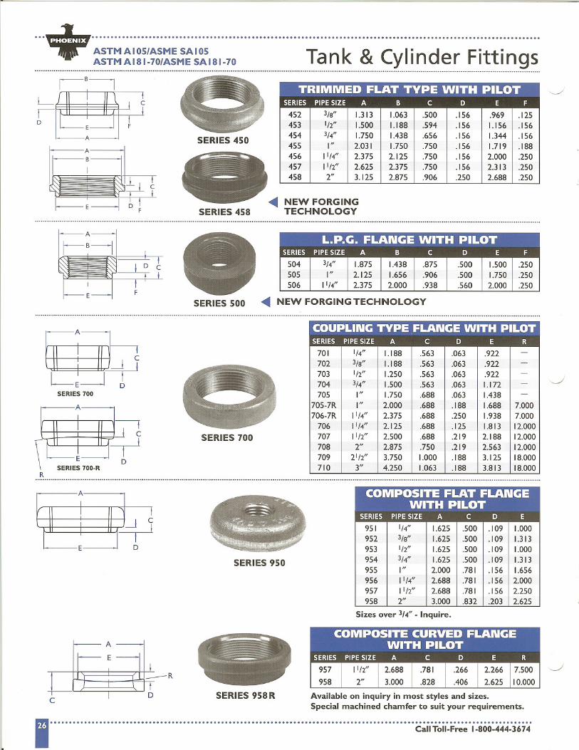
TRIMMED FLAT TYPE WITH PILOT_________________.0.SERIES PIPESIZE A B C D E F
452 3/B" 1.313 1.063 .500 .156 .969 .125453 1/2" 1.500 1.188 .594 .156 1.156 .156454 3/4" 1.750 1.438 .656 .156 1.344 .156455 I" 2.031 1.750 .750 .156 1.719 .188456 11/4" 2.375 2.125 .750 .156 2.000 .250457 11/2" 2.625 2.375 .750 .156 2.313 .250458 2" 3.125 2.875 .906 .250 2.688 .250
L.P.G. FLANGE WITH PILOT--- ------....- .. . . -SERIES PIPESIZE A B C D E F
504 3/4" 1.875 1.438 .875 .500 1.500 .250505 I" 2.125 1.656 .906 .500 1.750 .250506 11/4" 2.375 2.000 .938 .560 2.000 .250
COUPLING TYPE ,FLANGE WITH PILOT- -- - -- . - . -. ..... -. . .SERIES PIPESIZE A C D E R
701 1/4" 1.188 .563 .063 .922 -
702 3/8" 1.188 .563 .063 .922 -
703 1/2" 1.250 .563 .063 .922 -
704 3/4" 1.500 .563 .063 1.172 -
705 I" 1.750 .688 .063 1.438 -
705-7R I" 2.000 .688 .188 1.688 7.000706-7R 11/4" 2.375 .688 .250 1.938 7.000
706 11/4" 2.125 .688 .125 1.813 12.000707 11/2" 2.500 .688 .219 2.188 12.000708 2" 2.875 .750 .219 2.563 12.000709 21/2" 3.750 1.000 .188 3.125 18.000710 3" 4.250 1.063 .188 3.813 18.000
COMPOSITE FLAT FLANGEWITH PILOT
SERIES PIPESIZE A C D E
951 1/4" 1.625 .500 .109 1.000952 3/8" 1.625 .500 .109 1.313953 1/2" 1.625 .500 .109 1.000954 3/4" 1.625 .500 .109 1.313955 I" 2.000 .781 .156 1.656956 11/4" 2.688 .781 .156 2.000957 11/2" 2.688 .781 .156 2.250958 2" 3.000 .832 .203 2.625
~ + .... .T k & C 1
8
d F8
tt 8 ASTMAIOS/ASME SAIOS
.an Y In er lings ASTMAI81-70/ASMESAI81-70
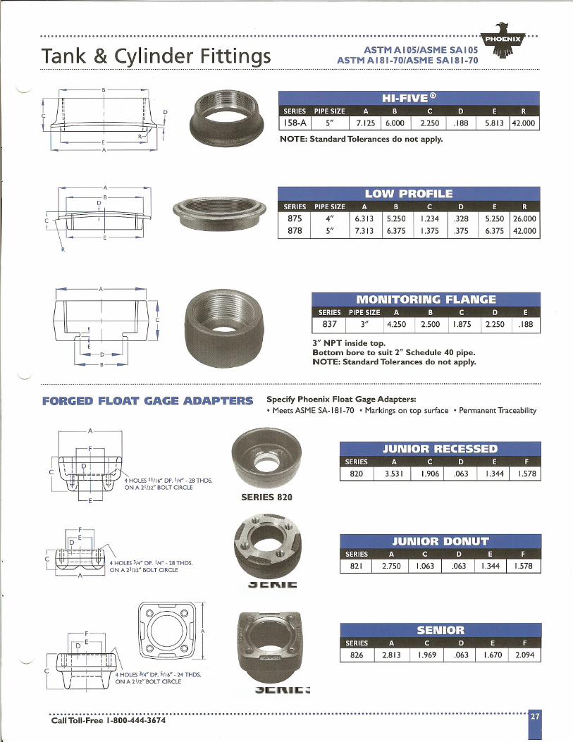
NOTE: Standard Tolerances do not apply.
R
3" NPT inside top.Bottom bore to suit 2" Schedule 40 pipe.NOTE: Standard Tolerances do not apply.
FORGED FLOAT GAGE ADAPTERS Specify Phoenix Float Gage Adapters:.Meets ASME SA-181-70 .Markings on top surface .Permanent Traceability
A
F
E
4 HOLES 11/16" DP. 1/4" - 28 THDS.ON A 21/32" BOLT CIRCLE
SERIES 820
SERIES 826
SERIES 821
---.....-- , 8
fC
lff- t
EA
RobertS
Stamp
RobertS
Note
MigrationConfirmed set by RobertS
RobertS
Stamp
+ ~.........................................................
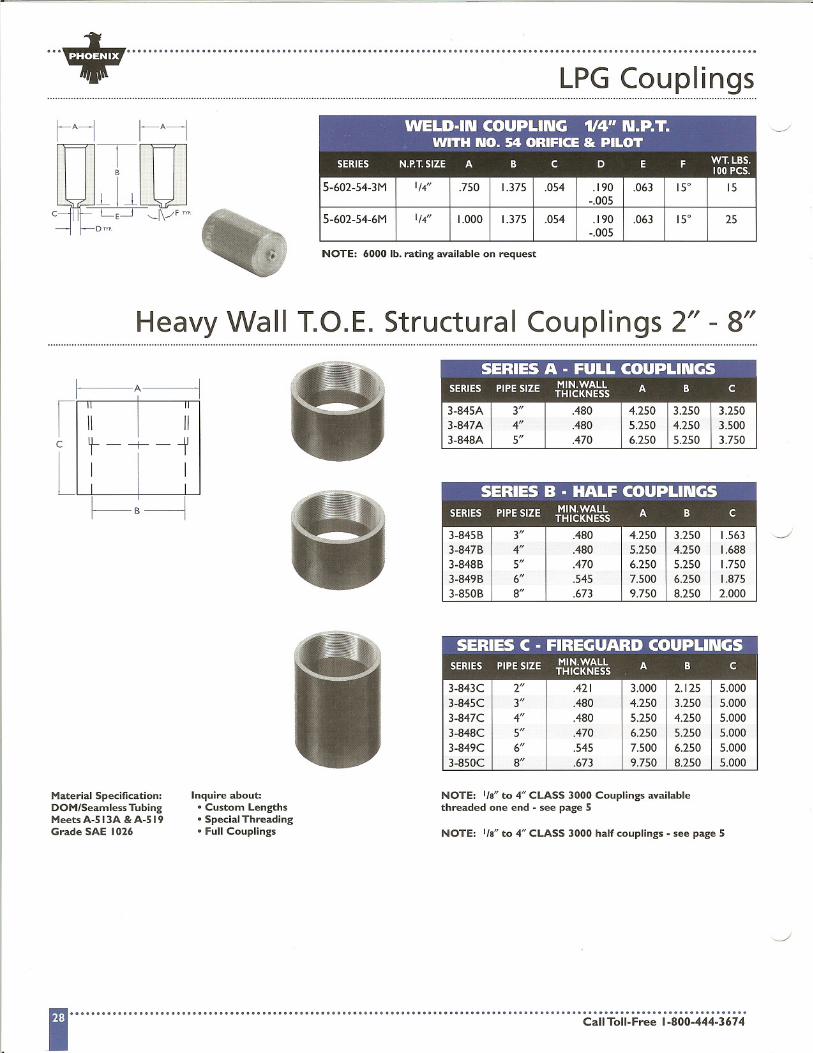
... . . LPG Couplings
NOTE: 6000 lb. rating available on request
Heavy Wall T.O.E. Structural Couplings 2" - 8"
Material Specification:DOM/Seamless TubingMeets A-SI3A &A-SI9Grade SAE 1026
Inquire about:.Custom Lengths.Special Threading.Full Couplings
SERIES A - FULL COUPLINGSMIN.WALL
SERIES PIPE SIZE THICKNESS ABC
3-845A3-847A3-848A
3"4"5"
3.2503.5003.750
.480
.480
.470
4.2505.2506.250
3.2504.2505.250
NOTE: I/s" to 4" CLASS 3000 Couplings availablethreaded one end -see page 5
NOTE: I/S" to 4" CLASS 3000 half couplings -see page 5
WELD-IN COUPLING 114" N.P.T.WITH NO. 54 ORIFICE & PILOT--,._...._..._... ...... .
SERIES N.P.T.SIZE A B C D E F WT. LBS.100PCS.
5-602-54-3M 1/4" .750 1.375 .054 .190 .063 15° 15-.005
5-602-54-6M 1/4" 1.000 1.375 .054 .190 .063 15° 25-.005
I
A
III I "
c --;--i
L I I I SERIES B -.HALF COUPLINGS-- - -- - - -
SERIES PIPESIZE MIN.WALL A B CTHICKNESS
3-845B 3" .480 4.250 3.250 1.5633-847B 4" .480 5.250 4.250 1.6883-848B 5" .470 6.250 5.250 1.7503-849B 6" .545 7.500 6.250 1.8753-850B 8" .673 9.750 8.250 2.000
SERIES C - FIREGUARD COUPLINGSSERIES PIPESIZE MIN.WALL A B C I
THICKNESS :
3-843C 2" .421 3.000 2.125 5.0003-845C 3" .480 4.250 3.250 5.0003-847C 4" .480 5.250 4.250 5.0003-848C 5" .470 6.250 5.250 5.0003-849C 6" .545 7.500 6.250 5.0003-850C 8" .673 9.750 8.250 5.000

,..
+ .... .L
"
ft"
L ASTMAIOS/ASME SAIOS
I In 9 u9 S LOAD RATING BASIS = 4 TIMES SAFETY FACTOR
Maximum load capacity per lug:4,850 Ibs.
UL RECOGNIZED
Maximum load capacity per lug:6,800 Ibs.
UL RECOGNIZED
Maximum load capacity per lug:20,000 Ibs.
UL RECOGNIZED
A
B
E
Maximum load capacity per lug:16,500 Ibs.
5\lLUL RECOGNIZED
B C
D-J L
Maximum load capacity per lug:11,450 Ibs.
A
UL RECOGNIZED
Maximum load capacity per lug:28,000 Ibs.
A
B
"c';'i T~i,:;';';';; ',..00:.;':':;",,;''' .. .. .. . .. ".. . .. .. . .. .. .. .. .. . .. ". . .. .. .. .. .. "".. .. .. .. .. .. .. .. .. .. .. . ".. .. .. .. .. .. .. .. ".. . .. ""I
I"='
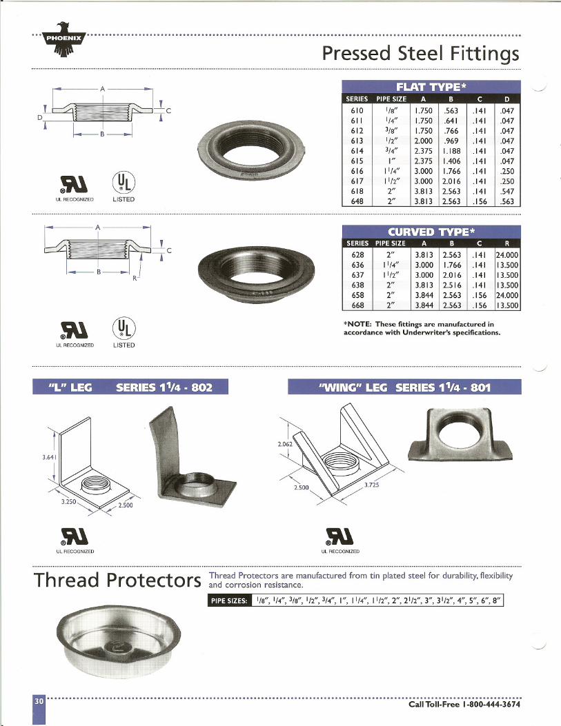
...+ ....................................................................................................................... .Pressed Steel Fittings
ULRECOGNIZED LISTED
@LISTEDUL RECOGNIZED
*NOTE: These fittings are manufactured inaccordance with Underwriter's specifications.
66L" LEG SERIES 11t4 . 802
UL RECOGNIZED
"WINCi" LECi SERIES 11t4 . 801
UL RECOGNIZED
Thread Protectors Thread Protectors are manufactured from tin plated steel for durability,flexibilityand corrosion resistance.
I/a", 1/4",3/a", 1/2",3/4", I", 11/4",11/2",2",21/2",3",31/2",4",5",6",8"
FLAT TYPE*_.._...................-.......___H____._____________
SERIES PIPESIZE A B C D
610 I/a" I.750 .563 .141 .047611 1/4" 1.750 .641 .141 .047612 3/a" 1.750 .766 .141 .047613 112" 2.000 .969 .141 .047614 3/4" 2.375 1.188 .141 .047615 I" 2.375 1.406 .141 .047616 11/4" 3.000 1.766 .141 .250617 1112" 3.000 2.016 .141 .250618 2" 3.813 2.563 .141 .547648 2" 3.813 2.563 .156 .563
CURVED TYPE*.............................-.----.--.-..-...-----..------------_.-------
SERIES PIPESIZE A B C R
628 2" 3.813 2.563 .141 24.000636 11/4" 3.000 1.766 .141 13.500637 1112" 3.000 2.016 .141 13.500638 2" 3.813 2.516 .141 13.500658 2" 3.844 2.563 .156 24.000668 2" 3.844 2.563 .156 13.500
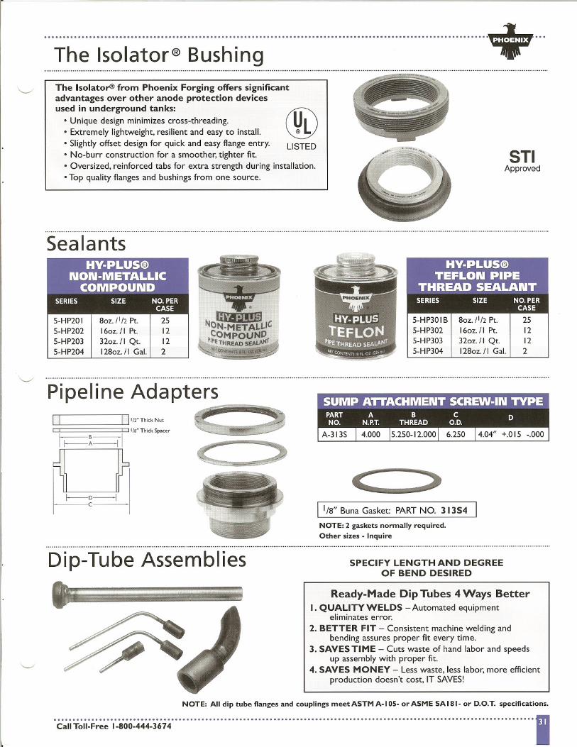
I + .... .The Isolator@ BushingThe Isolator@>from Phoenix Forging offers significantadvantages over other anode protection devicesused in underground tanks:
@.Unique design minimizes cross-threading. U.Extremely lightweight, resilient and easy to install. @L.Slightlyoffset design for quick and easy flange entry. LISTED.No-burr construction for a smoother, tighter fit.. Oversized, reinforced tabs for extra strength during installation..Top quality flanges and bushings from one source.
STIApproved
Sealants
5-HP20 I5-HP2025-HP2035-HP204
8oz. 11/2Pt. 2516oz./I Pt. 12
32oz./I Qt. 12128oz.II Gal. 2
Pipeline Adapters~-~II I
'il ~-,i
11/2" Thick Nut
Ilia" Thick Spacer
11/8" Buna Gasket: PART NO. 3 13S4
NOTE: 2 gaskets normally required.Other sizes - Inquire
Dip-Tube Assemblies SPECIFY LENGTH AND DEGREEOF BEND DESIRED
Ready-Made Dip Tubes 4 Ways BetterI. QUALITY WELDS - Automated equipment
eliminates error.2. BETTER FIT - Consistent machine welding and
bending assures proper fit every time.3. SAVES TIME - Cuts waste of hand labor and speeds
up assembly with proper fit.4. SAVES MONEY - Less waste, less labor, more efficient
production doesn't cost. IT SAVES!
NOTE: All dip tube flanges and couplings meet ASTM A-I 05- or ASME SA 181- or D.O:r. specifications.
oc';'iT~i~F;;';;0,:0.0444.36,.;0 00.. 0.. 0 0 0 00.. 00.. 0 0" 0 000.. 00 0 0.. 0.. 01
HY-PLUS@TEFLON PIPE
THREAD SEALANT-SERIES SIZE NO.PER
CASE.
5-HP30 IB 8oz./l/2 Pt. 255-HP302 16oz./1 Pt. 125-HP303 32oz./1 Qt. 125-HP304 I28oz. II Gal. 2


![Untitled Page [] MCHF-013-1...Oxygen Tank on Trolley Cylinder Size: 52"H x 9"Diameter weight: 1701bs Volume of Gas: 250 Cubic Feet Standard K size oxygen tank and regulator, cylinder](https://static.fdocuments.in/doc/165x107/611828fca7813e2aa7594943/untitled-page-mchf-013-1-oxygen-tank-on-trolley-cylinder-size-52h.jpg)