Tag Tables - University of Wisconsin–Madison
12
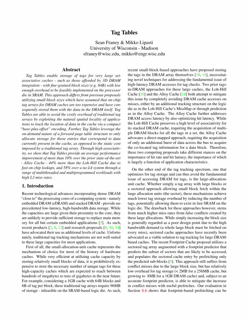
Tag Tables Sean Franey & Mikko Lipasti University of Wisconsin - Madison [email protected], [email protected] Abstract Tag Tables enable storage of tags for very large set- associative caches - such as those afforded by 3D DRAM integration - with fine-grained block sizes (e.g. 64B) with low enough overhead to be feasibly implemented on the processor die in SRAM. This approach differs from previous proposals utilizing small block sizes which have assumed that on-chip tag arrays for DRAM caches are too expensive and have con- sequently stored them with the data in the DRAM itself. Tag Tables are able to avoid the costly overhead of traditional tag arrays by exploiting the natural spatial locality of applica- tions to track the location of data in the cache via a compact “base-plus-offset” encoding. Further, Tag Tables leverage the on-demand nature of a forward page table structure to only allocate storage for those entries that correspond to data currently present in the cache, as opposed to the static cost imposed by a traditional tag array. Through high associativ- ity, we show that Tag Tables provide an average performance improvement of more than 10% over the prior state-of-the-art - Alloy Cache - 44% more than the Loh-Hill Cache due to fast on-chip lookups, and 58% over a no-L4 system through a range of multithreaded and multiprogrammed workloads with high L3 miss rates. 1. Introduction Recent technological advances incorporating dense DRAM “close to” the processing cores of a computing system - namely embedded DRAM (eDRAM) and stacked DRAM - provide un- precedented low-latency, high-bandwidth data storage. While the capacities are large given their proximity to the core, they are unlikely to provide sufficient storage to replace main mem- ory for all but certain embedded applications [5]. As such, recent products [2, 8, 12] and research proposals [9, 10, 14] have advocated their use as additional levels of cache. Unfortu- nately, traditional tag tracking mechanisms are not well-suited to these large capacities for most applications. First of all, the small-allocation-unit cache represents the mechanism of choice for most of the history of hardware caches. While very efficient at utilizing cache capacity by storing relatively small blocks of data, it is prohibitively ex- pensive to store the necessary number of unique tags for these high-capacity caches which are expected to reach between hundreds of megabytes to tens of gigabytes in the near future. For example, considering a 1GB cache with 64B blocks and 6B of tag per block, these traditional tag arrays require 96MB of storage - infeasible on the SRAM-based logic die. As such, recent small-block-based approaches have proposed storing the tags in the DRAM array themselves [10, 14], necessitat- ing novel techniques for addressing the fundamental issue of high-latency DRAM accesses for tag checks. Two prior tags- in-DRAM approaches for these large caches, the Loh-Hill Cache [10] and the Alloy Cache [14] both attempt to mitigate this issue by completely avoiding DRAM cache accesses on misses, either by an additional tracking structure on the logic die as in the Loh-Hill Cache’s MissMap or through prediction as in the Alloy Cache. The Alloy Cache further addresses DRAM access latency by also optimizing hit latency. While the Loh-Hill Cache preserves a high level of associativity for its stacked DRAM cache, requiring the acquisition of multi- ple DRAM blocks for all the tags in a set, the Alloy Cache advocates a direct-mapped approach, requiring the acquisition of only an additional burst of data across the bus to acquire the co-located tag information for a data block. Therefore, these two competing proposals take different stances on the importance of hit rate and hit latency, the importance of which is largely a function of application characteristics. On the other end of the tag tracking spectrum, one that optimizes for tag storage and can thus avoid the fundamental issue of accessing DRAM for tags, is the large-allocation- unit cache. Whether simply a tag array with large blocks or a sectored approach allowing small block fetch within the large allocation units (the sector), these mechanisms achieve much lower tag storage overhead by reducing the number of tags, potentially allowing them to exist in fast SRAM on the logic die. The drawback for these approaches however, stems from much higher miss rates from false conflicts created by these large allocations. While simply increasing the block size is generally regarded as a poor design point due to the high bandwidth demand (a whole large block must be fetched on every miss), sectored cache approaches have recently been advocated as a viable solution to tag tracking for large DRAM- based caches. The recent Footprint Cache proposal utilizes a sectored tag array augmented with a footprint predictor that predicts the subset of sectors that are likely to be accessed, and populates the sectored cache entry by prefetching only the predicted sub-blocks [9]. This approach still suffers from conflict misses due to the large block size, but has relatively low overhead for tag storage (< 2MB for a 256MB cache, but growing to 8MB for a 1GB DRAM cache) and, subject to an accurate footprint predictor, is able to mitigate the increase in conflict misses with useful prefetches. Our evaluation in Section 8.6 shows that footprint-based prefetching can be
Transcript of Tag Tables - University of Wisconsin–Madison
Tag Tables
Sean Franey & Mikko LipastiUniversity of Wisconsin - Madison
[email protected], [email protected]
AbstractTag Tables enable storage of tags for very large set-
associative caches - such as those afforded by 3D DRAMintegration - with fine-grained block sizes (e.g. 64B) with lowenough overhead to be feasibly implemented on the processordie in SRAM. This approach differs from previous proposalsutilizing small block sizes which have assumed that on-chiptag arrays for DRAM caches are too expensive and have con-sequently stored them with the data in the DRAM itself. TagTables are able to avoid the costly overhead of traditional tagarrays by exploiting the natural spatial locality of applica-tions to track the location of data in the cache via a compact
“base-plus-offset” encoding. Further, Tag Tables leverage theon-demand nature of a forward page table structure to onlyallocate storage for those entries that correspond to datacurrently present in the cache, as opposed to the static costimposed by a traditional tag array. Through high associativ-ity, we show that Tag Tables provide an average performanceimprovement of more than 10% over the prior state-of-the-art- Alloy Cache - 44% more than the Loh-Hill Cache due tofast on-chip lookups, and 58% over a no-L4 system through arange of multithreaded and multiprogrammed workloads withhigh L3 miss rates.
1. IntroductionRecent technological advances incorporating dense DRAM“close to” the processing cores of a computing system - namelyembedded DRAM (eDRAM) and stacked DRAM - provide un-precedented low-latency, high-bandwidth data storage. Whilethe capacities are large given their proximity to the core, theyare unlikely to provide sufficient storage to replace main mem-ory for all but certain embedded applications [5]. As such,recent products [2, 8, 12] and research proposals [9, 10, 14]have advocated their use as additional levels of cache. Unfortu-nately, traditional tag tracking mechanisms are not well-suitedto these large capacities for most applications.
First of all, the small-allocation-unit cache represents themechanism of choice for most of the history of hardwarecaches. While very efficient at utilizing cache capacity bystoring relatively small blocks of data, it is prohibitively ex-pensive to store the necessary number of unique tags for thesehigh-capacity caches which are expected to reach betweenhundreds of megabytes to tens of gigabytes in the near future.For example, considering a 1GB cache with 64B blocks and6B of tag per block, these traditional tag arrays require 96MBof storage - infeasible on the SRAM-based logic die. As such,
recent small-block-based approaches have proposed storingthe tags in the DRAM array themselves [10, 14], necessitat-ing novel techniques for addressing the fundamental issue ofhigh-latency DRAM accesses for tag checks. Two prior tags-in-DRAM approaches for these large caches, the Loh-HillCache [10] and the Alloy Cache [14] both attempt to mitigatethis issue by completely avoiding DRAM cache accesses onmisses, either by an additional tracking structure on the logicdie as in the Loh-Hill Cache’s MissMap or through predictionas in the Alloy Cache. The Alloy Cache further addressesDRAM access latency by also optimizing hit latency. Whilethe Loh-Hill Cache preserves a high level of associativity forits stacked DRAM cache, requiring the acquisition of multi-ple DRAM blocks for all the tags in a set, the Alloy Cacheadvocates a direct-mapped approach, requiring the acquisitionof only an additional burst of data across the bus to acquirethe co-located tag information for a data block. Therefore,these two competing proposals take different stances on theimportance of hit rate and hit latency, the importance of whichis largely a function of application characteristics.
On the other end of the tag tracking spectrum, one thatoptimizes for tag storage and can thus avoid the fundamentalissue of accessing DRAM for tags, is the large-allocation-unit cache. Whether simply a tag array with large blocks ora sectored approach allowing small block fetch within thelarge allocation units (the sector), these mechanisms achievemuch lower tag storage overhead by reducing the number oftags, potentially allowing them to exist in fast SRAM on thelogic die. The drawback for these approaches however, stemsfrom much higher miss rates from false conflicts created bythese large allocations. While simply increasing the block sizeis generally regarded as a poor design point due to the highbandwidth demand (a whole large block must be fetched onevery miss), sectored cache approaches have recently beenadvocated as a viable solution to tag tracking for large DRAM-based caches. The recent Footprint Cache proposal utilizes asectored tag array augmented with a footprint predictor thatpredicts the subset of sectors that are likely to be accessed,and populates the sectored cache entry by prefetching onlythe predicted sub-blocks [9]. This approach still suffers fromconflict misses due to the large block size, but has relativelylow overhead for tag storage (< 2MB for a 256MB cache, butgrowing to 8MB for a 1GB DRAM cache) and, subject to anaccurate footprint predictor, is able to mitigate the increasein conflict misses with useful prefetches. Our evaluation inSection 8.6 shows that footprint-based prefetching can be

easily adapted to our proposal for tag tables, and has thepotential to provide significant performance gains.
As a mechanism to provide many of the key features of theprior techniques, this paper presents Tag Tables. Tag Tablesprovide low latency tag check facilities on-par with the AlloyCache while maintaining the associativity - and thus hit rate- of the Loh-Hill cache. Further, Tag Tables provide a smallstorage overhead for tags in line with previously proposedsectored-like approaches such as the Footprint Cache, allowingthe tags to be stored on the fast SRAM-based logic die whilemaintaining traditional small block sizes (64B as evaluated).Tag Tables achieve these seemingly contradictory goals byleveraging the naturally-present spatial locality of applicationworking sets that is enhanced by the longer residency times ofdata in these high-capacity DRAM caches by utilizing a base-plus-offset encoding of “chunks” of contiguous data in thecache. Further, Tag Tables are implemented as a forward pagetable stored in the existing L3 cache resources of the chip,allowing tag storage overhead to be dynamically balancedwith on-chip caching resources. The remainder of the paperwill elaborate on the specific mechanisms that achieve thesefeatures.
2. MotivationAs a means to place these competing ideologies into perspec-tive, Figure 1 presents the ”Bandwidth-Delay product” (BDP)achieved versus the tag storage overhead of a broad rangeof DRAM cache tag storage configurations. The compoundBDP metric attempts to quantify the major benefits soughtwith caching: reduced off-chip bandwidth and improved ap-plication performance through high speed data access, wherea lower value is better. The shaded area at the bottom left ofthe figure captures designs that have lower BDP than a base-line system without a DRAM cache, and have a reasonable(defined here as 6MB) SRAM cost for tags.
Along with the Loh-Hill Cache ( ), the Alloy Cache( ), and Tag Table ( ) configurations, a family of curves ispresented in the figure for a large-allocation-unit mechanismthat attempts to reduce tag overhead by increasing block size.The graph clearly shows that the large allocation approach- which evaluates block sizes from 64B to 512B - fails toachieve good performance, either consuming too much off-chip bandwidth to fetch its large blocks and/or incurring toomany misses due to false conflicts. In contrast, the Loh-HillCache, the Alloy Cache, and Tag Tables all reside within thedesirable portion of the graph with the Tag Table configurationproviding the best BDP (Section 8.4 will discuss the mainfeatures that distinguish Tag Tables from both the Alloy Cacheand Loh-Hill Cache).
Further, while the Tag Table configuration exists to the rightof the Alloy Cache, indicating increased SRAM storage re-quirement, this is the complete tag storage overhead (i.e., notag information needs to consume DRAM cache capacity). Inaddition, the Tag Table achieves its performance without any
0
0.5
1
1.5
2
2.5
3
0 2 4 6 8 10 12 14 16
Ban
dw
idth
-De
lay
Pro
du
ct (
BD
P)
- N
orm
aliz
ed
SRAM Cost (MB)
124816
Associativity
Figure 1: Performance of various cache configurations for a 256 MB L4cache. Shaded area indicates desirable region of improvedbandwidth-delay with practical SRAM cost. Results shown for thePARSEC canneal benchmark normalized to a baseline with no L4.
prediction or SRAM-based hit/miss determination structuresas the other three state-of-the-art techniques rely on. In factprediction is an orthogonal technique that is equally applica-ble to Tag Tables thus they can be extended by any one of anumber of prediction schemes to achieve even better perfor-mance (Section 8.6 will investigate the opportunity footprintprediction might have for Tag Tables).
2.1. Additional Related Work
The structure of Tag Tables are partly inspired by prior work inmemory protection and address translation. Mondrian Mem-ory Protection (MMP) argues for fine-grained protection do-mains and proposes a practical implementation scheme thatexploits spatial locality similar to that exhibited by applicationcache accesses and exploited by our Tag Table. MMP exploitsthese observations through both a forward page table structureand base-plus-offset encoding of entries [19]. In a similar vein,Coalesced Large-Reach TLBs (CoLT) uses a base-plus-offsetencoding to track many contiguous virtual-to-physical pagemappings [13].
3. Page WalkThis section presents the fundamental data structure of TagTables, which is based on the tree structure used to implementa forward page table.
3.1. Page Tables
Motivated by Figure 1, we begin to develop a more compactstorage mechanism for large cache tags by arguing that anyextension of a traditional tag array will be unable to exploitruntime features of the system to achieve storage savings be-cause they impose a static storage requirement. Regardless ofthe state of the cache, the one-to-one mapping of cache blocksto tags in a traditional tag array means that it must provisionstorage equal to the product of the number of blocks in thecache and the storage required per tag. This feature is analo-gous to another mechanism for tracking memory metadata -the inverted page table (IPT). Similar to the tag array, the IPThas a one-to-one mapping of physical pages to entries and im-poses a static storage requirement proportional to the numberof physical pages. Unlike a traditional tag array however, a
2

root
Lvl1 Ptr
Lvl 1
Lvl2 Ptr
Lvl 3
Way
Lvl 2
Lvl3 Ptr
Root Index Lvl 1 Index Lvl 2 Index Lvl 3 Index Block Offset
Address
Figure 2: High level operation of a forward-page-table-based implementa-tion of cache tags.
page table has an alternate implementation to the IPT - theforward page table (FPT) - that only requires storage relativeto the number of mapped pages. In other words, no storageoverhead is incurred for a memory page that is unmapped inan FPT. Therefore, as a starting point for developing a morerobust solution to tag storage for large caches, we investigateopportunities for adapting the FPT mechanism which providesus with the flexibility to adapt to application behavior andfrees us from an inflexible requirement that cannot be adaptedon-demand to system needs.
At a high level, the replacement of a traditional tag arrayby a page table implementation is straightforward and followsthe operation outlined by Figure 2. Upon access, a tag checkoccurs as a virtual address translation does in a forward pagetable through indexing the various levels of the table with ap-propriate bits of the access’s address. The “walk” terminateswhen either all bits are exhausted and a leaf entry is found -storing the way associated with the tag, if the cache is associa-tive - or the branch terminates prematurely indicating a miss.In the end, all bits of the address above the block offset havebeen used to arrive to a unique location in the table for theaddress. This operation is analogous to the page table whereall of the bits of the address above the page offset are used totraverse to a unique leaf. A miss would then trigger insertionof the data in the cache and tracking of the tag in the tableby extending the branch to a leaf and storing the appropriateway in the leaf as identified by an eviction mechanism whichis unchanged from a traditional cache (e.g., selection of theleast recently used member of the set). In and of itself, thechoice of this data structure in Tag Tables is not a fundamentalimprovement as the combination of multiple levels and waystorage in the leaf is not inherently less expensive or fasterthan a traditional tag structure. It does however, provide astarting point that frees Tag Tables from inflexible storagerequirements and represents a structure that is able to adapt tosystem operating characteristics.
3.2. Locating Metadata
As with any tag tracking structure - especially one for high-capacity caches - the storage location of the metadata is aprimary concern. By metadata, we are referring to the datathat is required in order to logically create the Tag Table:the leaf entries storing way information and the pointers tosubsequent levels. In a traditional tag array, this metadata is thetags themselves. While the Loh-Hill Cache and Alloy Cachechoose to store their metadata (cache tags) in the stackedDRAM array itself, Tag Tables adopt the page table approachand store its metadata in memory, specifically the L3 cache.While it would be possible to dedicate a structure by “carving”out a portion of the L3 cache as is proposed for the “MissMap”access predictor in the Loh-Hill cache [10], locating Tag Tablemetadata dynamically in the L3 allows a system with TagTables to quickly perform table walks and balance metadatawith application data through the existing cache replacementpolicy.
This competition of metadata with application data is al-lowed without restriction up to a “high watermark.” This highwatermark is enforced on a per-set basis and is necessary tolimit the number of ways in the set that can be occupied at anygiven time with metadata. This restriction is placed to preventexcessive pollution by metadata that could otherwise severelyharm application performance. This is particularly a concernin the situation where the L3 cache is capable of storing themajor portions - if not all - of the application’s working set (asituation not that uncommon for typical L3 cache sizes andmany applications). Since metadata effectively reduces thecapacity of the L3 for application data, such pollution couldresult in the working set no longer fitting, severely impactingperformance. Section 8 will evaluate the effect of differenthigh watermark settings on Tag Table performance.
4. Reducing Levels Traversed
Although a traditional page walk can work correctly to performa tag check as described, this section describes two opportu-nities afforded Tag Tables to accelerate these walks. Theseopportunities arise from the different needs of a tag checkrelative to an address translation.
4.1. Walk Bit Selection
First of all, unlike a traditional page table, Tag Tables canreverse the order of the bits used to index various levels inorder to utilize the high entropy bits to index the upper levelentries. This is useful since Tag Tables, like traditional tagarrays, would like to use these high entropy, low-order bits todefine the set associated with the data to more evenly utilizecache capacity (as labeled in Figure 3 as “Row Selection Bits”).While utilizing high order bits for upper levels of a page tableis advantageous for translating virtual to physical addressesby allowing page size to be implied by a translation’s locationin the table, Tag Tables do not benefit from such support and
3
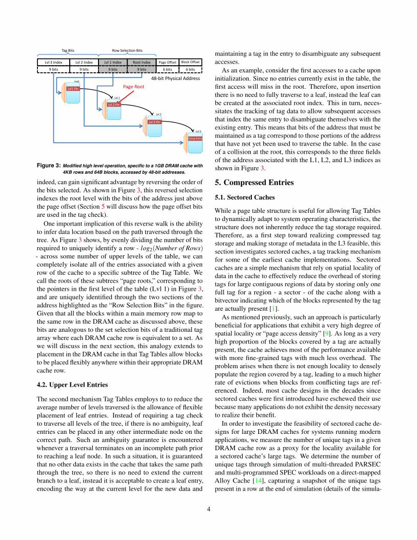
root
Lvl1 Ptr
Lvl 1
Lvl 2
Lvl 3 Index Lvl 2 Index Lvl 1 Index Root Index Page Offset
48-bit Physical Address
Tag Bits Row Selection Bits
Block Offset
9 bits 9 bits 9 bits 9 bits 6 bits 6 bits
Page Root
Comp Entry
Lvl 3 Ptr
Lvl 2 Ptr
Lvl 3
Figure 3: Modified high level operation, specific to a 1GB DRAM cache with4KB rows and 64B blocks, accessed by 48-bit addresses.
indeed, can gain significant advantage by reversing the order ofthe bits selected. As shown in Figure 3, this reversed selectionindexes the root level with the bits of the address just abovethe page offset (Section 5 will discuss how the page offset bitsare used in the tag check).
One important implication of this reverse walk is the abilityto infer data location based on the path traversed through thetree. As Figure 3 shows, by evenly dividing the number of bitsrequired to uniquely identify a row - log2(Number of Rows)- across some number of upper levels of the table, we cancompletely isolate all of the entries associated with a givenrow of the cache to a specific subtree of the Tag Table. Wecall the roots of these subtrees “page roots,” corresponding tothe pointers in the first level of the table (Lvl 1) in Figure 3,and are uniquely identified through the two sections of theaddress highlighted as the “Row Selection Bits” in the figure.Given that all the blocks within a main memory row map tothe same row in the DRAM cache as discussed above, thesebits are analogous to the set selection bits of a traditional tagarray where each DRAM cache row is equivalent to a set. Aswe will discuss in the next section, this analogy extends toplacement in the DRAM cache in that Tag Tables allow blocksto be placed flexibly anywhere within their appropriate DRAMcache row.
4.2. Upper Level Entries
The second mechanism Tag Tables employs to to reduce theaverage number of levels traversed is the allowance of flexibleplacement of leaf entries. Instead of requiring a tag checkto traverse all levels of the tree, if there is no ambiguity, leafentries can be placed in any other intermediate node on thecorrect path. Such an ambiguity guarantee is encounteredwhenever a traversal terminates on an incomplete path priorto reaching a leaf node. In such a situation, it is guaranteedthat no other data exists in the cache that takes the same paththrough the tree, so there is no need to extend the currentbranch to a leaf, instead it is acceptable to create a leaf entry,encoding the way at the current level for the new data and
maintaining a tag in the entry to disambiguate any subsequentaccesses.
As an example, consider the first accesses to a cache uponinitialization. Since no entries currently exist in the table, thefirst access will miss in the root. Therefore, upon insertionthere is no need to fully traverse to a leaf, instead the leaf canbe created at the associated root index. This in turn, neces-sitates the tracking of tag data to allow subsequent accessesthat index the same entry to disambiguate themselves with theexisting entry. This means that bits of the address that must bemaintained as a tag correspond to those portions of the addressthat have not yet been used to traverse the table. In the caseof a collision at the root, this corresponds to the three fieldsof the address associated with the L1, L2, and L3 indices asshown in Figure 3.
5. Compressed Entries
5.1. Sectored Caches
While a page table structure is useful for allowing Tag Tablesto dynamically adapt to system operating characteristics, thestructure does not inherently reduce the tag storage required.Therefore, as a first step toward realizing compressed tagstorage and making storage of metadata in the L3 feasible, thissection investigates sectored caches, a tag tracking mechanismfor some of the earliest cache implementations. Sectoredcaches are a simple mechanism that rely on spatial locality ofdata in the cache to effectively reduce the overhead of storingtags for large contiguous regions of data by storing only onefull tag for a region - a sector - of the cache along with abitvector indicating which of the blocks represented by the tagare actually present [1].
As mentioned previously, such an approach is particularlybeneficial for applications that exhibit a very high degree ofspatial locality or “page access density” [9]. As long as a veryhigh proportion of the blocks covered by a tag are actuallypresent, the cache achieves most of the performance availablewith more fine-grained tags with much less overhead. Theproblem arises when there is not enough locality to denselypopulate the region covered by a tag, leading to a much higherrate of evictions when blocks from conflicting tags are ref-erenced. Indeed, most cache designs in the decades sincesectored caches were first introduced have eschewed their usebecause many applications do not exhibit the density necessaryto realize their benefit.
In order to investigate the feasibility of sectored cache de-signs for large DRAM caches for systems running modernapplications, we measure the number of unique tags in a givenDRAM cache row as a proxy for the locality available fora sectored cache’s large tags. We determine the number ofunique tags through simulation of multi-threaded PARSECand multi-programmed SPEC workloads on a direct-mappedAlloy Cache [14], capturing a snapshot of the unique tagspresent in a row at the end of simulation (details of the simula-
4

0
0.1
0.2
0.3
0.4
0.5
0.6
0.7
0.8
0.9
1
0 2 4 6 8 10 12 14 16
Cu
mu
lati
ve
Pro
po
rtio
n o
f R
ow
s w
ith
Le
ss
or
Eq
ua
l U
niq
ue
Ta
gs
Number of Unique Tags
blackscholes
bodytrack
bwaves
canneal
dedup
facesim
ferret
fluidanimate
gcc
lbm
libquantum
mcf
milc
omnetpp
raytrace
soplex
Figure 4: Cumulative proportion of DRAM cache rows with less than orequal to a given number of unique tags.
tion parameters are given in Section 8). Presented in Figure 4,this evaluation indicates that modern applications exhibit awide range of locality characteristics. The figure relates thecumulative proportion of the cache’s rows that exhibit a givenx-value’s number of unique tags. For instance, mcf has nearly40% of its cache’s rows with more than 8 unique tags (60% ofthe rows have less than or equal to 8 tags). The page size inves-tigated is 4 KB and it can be seen that for many applications,most rows in the cache have very few unique tags as evidencedby the sharp slope in the graph for low values of unique tags,identifying them as potentially good candidates for a sectoredcache. A significant number of other applications however,such as mcf and omnetpp, unfortunately exhibit few rowswith high locality as evidenced by their graph’s relatively flatgrowth at low unique tag counts. Finally, despite indicationsthat perhaps many applications may benefit from a sectoredtag approach, i.e. those with steep slopes to the left end ofthe graph, it should be noted that for a 256MB cache, 64Bblocks and 256B per sector (i.e., 4 blocks per sector) the stor-age overhead of the tag array is still 5MB. This penalty growsnear-linearly with cache size (neglecting the minor changein tag size per sector due to larger caches) resulting in muchhigher cost as cache size increases. Together, this data jus-tifies the absence of sectored cache designs in current cacheimplementations due to its severe penalty of several importantapplication types and motivates us to identify a more robustmechanism for reducing the storage requirement of cache tags.
Motivated by the results of Figure 4 which indicate a rangeof spatial locality within a cache both over rows within thecache and from application to application, we seek to createa space-efficient entry type that can robustly adapt to thesedifferent scenarios. While the figure shows that the rigidlyimposed spatial locality required by a sectored cache does notmap well to many applications, it also indicates that there issignificant opportunity if a sectored-tag-like approach wereavailable for some applications and regions of the cache. Inorder to realize such a robust tracking mechanism, we proposethe use of a “base-plus-offset” encoding for tracking regionsof memory in the cache. Rather than imposing static region
(a)
Offset Length
Chunk 2
Offset Length
Chunk 3
Offset Length
Chunk 4
Tag Offset Length
Chunk 1
(b)
Figure 5: Basic & Expanded Entry Formats.
sizes and boundaries and tracking the blocks within throughthe sectored approach’s bitvector, we propose instead storingthe tag associated with the bottom block of a “chunk” of dataand indicating the number of contiguous blocks from that baseblock with a count value1. Such an encoding can be seenin Figure 5a, showing a field for a simple tag followed by afield that indicates the number of contiguous blocks existingbeyond that base.
Unlike a bitvector which requires a bit for every block,this length indication only requires log2(Max. no. blocks) bits.The tradeoff of course, is that this encoding cannot track arange with “holes” (i.e., non-present blocks within the chunk)in it. To address this issue, we propose a hybrid approachby introducing some number of chunk representations greaterthan one as shown in Figure 5b, allowing us to represent holesimplicitly in the gaps between chunks. In this format, inaddition to the tag and length previously discussed, we alsomust utilize an “offset” specification that relates the first blockof the chunk to the tag of the entry. For example, an “offset”of ’4’ indicates that the first block of the chunk exists fourblocks beyond the base block identified by the tag.
When combined with the forward page table structure pro-posed in Section 3.1, by replacing the simple way-identifyingentries proposed at the leaf of the page table with these com-pressed entries, we free ourselves from a one-to-one mappingof blocks present in the cache to leaf entries in the page tablestructure. This allows us to amortize our inherently larger en-tries over a greater range of blocks. Section 8 will quantify thisamortization by showing that the average number of blockstracked per entry is actually quite high for those applicationsin our benchmark set.
6. Operation
This section provides discussion of the operation of Tag Tables,utilizing all of the components so far described. The basic TagTable structure tracks tags in a large cache and operates - at ahigh level - as a forward page table with tag checks implicitwith a walk of the table. The exact location of data is stored incompressed form at leaf entries with base-plus-offset encodingand misses are either implied by failure to find a complete pathto a leaf or by a block not residing in any of the leaf entry’schunks.
1Specifically, for the remainder of the paper, when we refer to a “chunk,”we mean a set of blocks present in the cache that are contiguous with oneanother in main memory.
5

6.1. Insertion
As with any cache, insertion of data is a fundamental op-erational issue for Tag Tables. Due to the structure of thecompressed entries, Tag Table efficiency is significantly im-pacted by the location of data. If placed intelligently, largecontiguous chunks can be created, amortizing the cost of anentry as additional blocks can be tracked by merely increment-ing the “length.” If placed poorly, this opportunity is missedand the inherently larger entries relative to a traditional tag canresult in a structure that is much larger than even a traditionaltag array.
Procedurally, insertion involves first building a bitvectorrepresenting all of the blocks present in the current block’sDRAM cache row. Thanks to the page roots discussed inSection 4.1, building this bitvector is isolated to the leavesassociated with the current block’s page root where traversalto each leaf and setting of all bits in the vector associatedwith the blocks tracked in the leaf’s chunks is sufficient topopulate the bitvector. While this may seem like a costlyevent, the optimization presented in Section 4.2 that allowsleaf entries to exist in intermediate levels can reduce this costwhen it is known that there is only one entry associated withthe DRAM cache row. In such a case, building the bitvectoronly requires inspecting the chunks of this single entry asopposed to potentially multiple traversals. Indeed, as willbe shown in Section 8, relatively few entries are frequentlynecessary per DRAM cache row, limiting the traversals neededto create the bitvector.
Following population of the bitvector, the Tag Table at-tempts to find a location for insertion by emphasizing exten-sion of existing chunks if such a chunk exists (i.e., eitherthe base or top of the chunk is contiguous with the insertedblock) and the bitvector indicates the appropriate position isfree in the row. If an existing chunk cannot be identified toextend, the Tag Table falls back to either randomly choosingan existing empty location if one exists, or randomly selectinga victim from the existing blocks. While there are poten-tially many improvements that can be made to this mechanism(more sophisticated replacement algorithms, etc.), simulationhas shown this simple approach works reasonably well, thuswe leave investigation into more sophisticated approaches forfuture work.
Further, while insertion can be a high latency event, particu-larly in the situation where a page root has many leaf entries,it occurs off of the critical path (i.e., data from the request ispassed on the L3 in parallel with the DRAM cache insertion)and follows the already high latency miss event that triggeredthe fill, thus its impact on performance is negligible. In addi-tion, while not evaluated for this proposal, it can be envisioned- for increased storage cost - that each page root entry canmaintain its own persistent bitvector, simply updating it oninsertions and evictions, removing the need to dynamicallyre-build it from scratch on each insertion.
6.2. Associativity
Prior work on DRAM cache tags have taken varying ap-proaches on the topic of associativity. Loh and Hill for one,choose to allow associativity up to the number of blocks ina DRAM cache row, less those blocks required to store taginformation (three blocks as presented) [10]. This is a keydesign point for their proposal as they rely on the guaranteedpage-open state the tag check provides them to limit hit la-tency. Since the row is already open, there is no advantagein their design to limit the associativity, and indeed there isbenefit to maintaining associativity, even in such large caches,as Figure 1 highlights. The Alloy Cache on the other hand, ex-plicitly eliminates associativity to optimize hit latency. Sincethe relative cost of accessing the tags necessary for supportingassociativity is so high in the Loh-Hill cache, the Alloy cacheargues there is substantial benefit to be realized by limitingthe number of tag checks. Given our Tag Table’s locationon-chip in SRAM however, it suffers from a tag access penaltymuch more in-line with other on-chip caches which have deter-mined that the cost of associativity is justified (an observationsubstantiated by Figure 1).
Therefore, for the insertion of data in a Tag-Table-administered cache, associativity similar to the Loh-Hill cacheis maintained in that placement of data is valid anywherewithin a DRAM cache row. While there is no benefit of aguaranteed open row access, there is essentially no advantage,latency-wise, by restricting data to any particular locationwithin the row. Instead, high associativity is particularly im-portant in an inclusive cache system beyond the inherent hitrate benefits of associativity which will be discussed in moredetail in Section 8.4.
In order to support this associativity, Tag Table compressedentries are provisioned to be able to fully track the blocks in aDRAM cache row. This means, that for 4KB pages and 64Bblocks, that each offset and length field must be 6 bits wide.This leads to the updated entry format presented in Figure 6whose new fields will be described fully in the summary ofthis section (Section 6.3), but notably convey the 6-bit offsetand length fields and introduce the “Row Offset” field whichrelates the page offset of the base of the chunk to the actuallocation in the DRAM cache row for that block. For example,consider the situation where a block at page offset of 0x4(relative to the base tag of the entry) is placed at location0x8 in the actual DRAM row (i.e., 8 blocks from the baseof the cache row). In this case, the chunk associated withthe page offset will have the value ’0x4’ in the “Page Offset”field (assuming it is the base of the chunk) and the value’0x8’ in the “Row Offset” field. This way, when a subsequentwalk traverses to this entry with a page offset of 0x4, it willknow that its data is physically located at block 0x8 of theappropriate DRAM cache row. Note, that if the page offsetwas 0x5 for an access, assuming it was present in the cache(implying a “length” of the chunk >1), the row offset returned
6
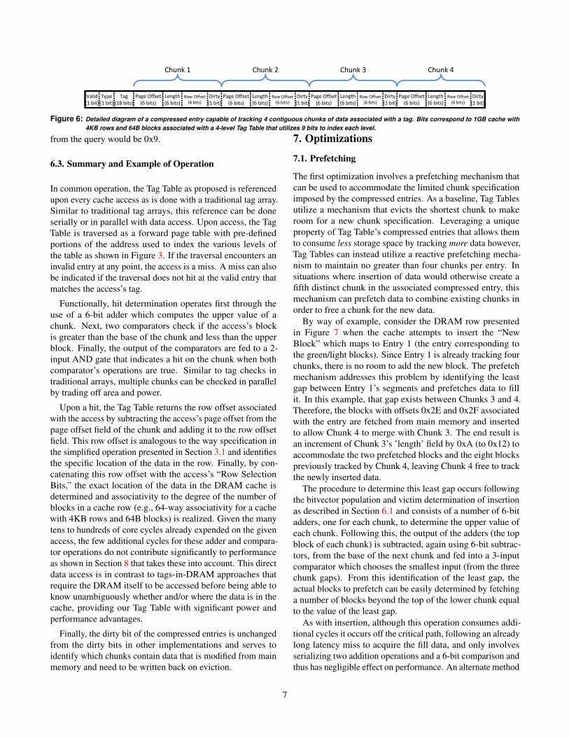
Valid
(1 bit)
Type
(1 bit)
Tag
(18 bits)
Page Offset
(6 bits)
Length
(6 bits)
Row Offset
(6 bits)
Dirty
(1 bit)
Chunk 1
Page Offset
(6 bits)
Length
(6 bits)
Row Offset
(6 bits)
Dirty
(1 bit)
Chunk 2
Page Offset
(6 bits)
Length
(6 bits)
Row Offset
(6 bits)
Dirty
(1 bit)
Chunk 3
Page Offset
(6 bits)
Length
(6 bits)
Row Offset
(6 bits)
Dirty
(1 bit)
Chunk 4
Figure 6: Detailed diagram of a compressed entry capable of tracking 4 contiguous chunks of data associated with a tag. Bits correspond to 1GB cache with4KB rows and 64B blocks associated with a 4-level Tag Table that utilizes 9 bits to index each level.
from the query would be 0x9.
6.3. Summary and Example of Operation
In common operation, the Tag Table as proposed is referencedupon every cache access as is done with a traditional tag array.Similar to traditional tag arrays, this reference can be doneserially or in parallel with data access. Upon access, the TagTable is traversed as a forward page table with pre-definedportions of the address used to index the various levels ofthe table as shown in Figure 3. If the traversal encounters aninvalid entry at any point, the access is a miss. A miss can alsobe indicated if the traversal does not hit at the valid entry thatmatches the access’s tag.
Functionally, hit determination operates first through theuse of a 6-bit adder which computes the upper value of achunk. Next, two comparators check if the access’s blockis greater than the base of the chunk and less than the upperblock. Finally, the output of the comparators are fed to a 2-input AND gate that indicates a hit on the chunk when bothcomparator’s operations are true. Similar to tag checks intraditional arrays, multiple chunks can be checked in parallelby trading off area and power.
Upon a hit, the Tag Table returns the row offset associatedwith the access by subtracting the access’s page offset from thepage offset field of the chunk and adding it to the row offsetfield. This row offset is analogous to the way specification inthe simplified operation presented in Section 3.1 and identifiesthe specific location of the data in the row. Finally, by con-catenating this row offset with the access’s “Row SelectionBits,” the exact location of the data in the DRAM cache isdetermined and associativity to the degree of the number ofblocks in a cache row (e.g., 64-way associativity for a cachewith 4KB rows and 64B blocks) is realized. Given the manytens to hundreds of core cycles already expended on the givenaccess, the few additional cycles for these adder and compara-tor operations do not contribute significantly to performanceas shown in Section 8 that takes these into account. This directdata access is in contrast to tags-in-DRAM approaches thatrequire the DRAM itself to be accessed before being able toknow unambiguously whether and/or where the data is in thecache, providing our Tag Table with significant power andperformance advantages.
Finally, the dirty bit of the compressed entries is unchangedfrom the dirty bits in other implementations and serves toidentify which chunks contain data that is modified from mainmemory and need to be written back on eviction.
7. Optimizations
7.1. Prefetching
The first optimization involves a prefetching mechanism thatcan be used to accommodate the limited chunk specificationimposed by the compressed entries. As a baseline, Tag Tablesutilize a mechanism that evicts the shortest chunk to makeroom for a new chunk specification. Leveraging a uniqueproperty of Tag Table’s compressed entries that allows themto consume less storage space by tracking more data however,Tag Tables can instead utilize a reactive prefetching mecha-nism to maintain no greater than four chunks per entry. Insituations where insertion of data would otherwise create afifth distinct chunk in the associated compressed entry, thismechanism can prefetch data to combine existing chunks inorder to free a chunk for the new data.
By way of example, consider the DRAM row presentedin Figure 7 when the cache attempts to insert the “NewBlock” which maps to Entry 1 (the entry corresponding tothe green/light blocks). Since Entry 1 is already tracking fourchunks, there is no room to add the new block. The prefetchmechanism addresses this problem by identifying the leastgap between Entry 1’s segments and prefetches data to fillit. In this example, that gap exists between Chunks 3 and 4.Therefore, the blocks with offsets 0x2E and 0x2F associatedwith the entry are fetched from main memory and insertedto allow Chunk 4 to merge with Chunk 3. The end result isan increment of Chunk 3’s ’length’ field by 0xA (to 0x12) toaccommodate the two prefetched blocks and the eight blockspreviously tracked by Chunk 4, leaving Chunk 4 free to trackthe newly inserted data.
The procedure to determine this least gap occurs followingthe bitvector population and victim determination of insertionas described in Section 6.1 and consists of a number of 6-bitadders, one for each chunk, to determine the upper value ofeach chunk. Following this, the output of the adders (the topblock of each chunk) is subtracted, again using 6-bit subtrac-tors, from the base of the next chunk and fed into a 3-inputcomparator which chooses the smallest input (from the threechunk gaps). From this identification of the least gap, theactual blocks to prefetch can be easily determined by fetchinga number of blocks beyond the top of the lower chunk equalto the value of the least gap.
As with insertion, although this operation consumes addi-tional cycles it occurs off the critical path, following an alreadylong latency miss to acquire the fill data, and only involvesserializing two addition operations and a 6-bit comparison andthus has negligible effect on performance. An alternate method
7

DRAM Row E1,C3 E1,C2 E1,C4 E1, C1 Entry 2, Chunk 1 E2,C2 E2,C3
1
Valid
1
Type Tag
0xA
Page Offset
0x5
Length
0xA
Row Offset
0
Dirty
Chunk 1
0x1D
Page Offset
0x4
Length
0x1D
Row Offset
1
Dirty
Chunk 2
0x26
Page Offset
0x8
Length
0x26
Row Offset
0
Dirty
Chunk 3
0x30
Page Offset
0x8
Length
0x30
Row Offset
0
Dirty
Chunk 4
1
Valid
1
Type Tag
0x0
Page Offset
0xA
Length
0x0
Row Offset
0
Dirty)
0x1D
Page Offset
0x4
Length
0x21
Row Offset
0
Dirty
0x38
Page Offset
0x8
Length
0x38
Row Offset
1
Dirty
N/A
Page Offset
0
Length
N/A
Row Offset
N/A
Dirty
0x0 0x3F 0x20
Entry 2
Entry 1
New Block
Figure 7: Example compressed entries associated with a DRAM cache row.
to maintain correctness however, which we will evaluate inSection 8.5, is to evict the shortest chunk instead.
7.2. Colocating Metadata
In addition to reducing the average number of L3 accesses formetadata by allowing compressed entries to exist in interme-diate levels as discussed in Section 4.2, Tag Table’s structureprovides an additional means for optimizing metadata retrieval.Assuming a system with a shared L3 that is physically com-posed of multiple, distributed slices, it is possible with ourTag Table’s tree structure to partition it in such a way that themetadata associated with a partition of the table be co-locatedwith the L3 slice that would trigger its access. If the bit in-terleavings associated with each slice of the L3 is static andknown at initialization, it is a simple matter to maintain thoseportions of the Tag Table on the paths associated with a givenslice at the L3 slice itself. This opportunity frees our Tag Tablestructure from the long latency accesses previously assumedfor DRAM cache metadata, specifically the 24 cycles assumedfor the MissMap [10]. Instead, considering a ring-based, 8-core CMP system, with one L3 slice per core, L3 accessesconsist of 1) communicating a request to and returning datafrom the proper slice, 2) accessing the tag information in thatslice, and 3) accessing the associated data (on a hit). Therefore,utilizing a uni-directional ring for inter-core communication,the communication portion of the latency comes to 16 corecycles round-trip on average assuming the network operates atcore frequency and only requires two cycles per hop (1 cyclefor switch traversal and 1 for link traversal). Following com-munication, accessing tags for a 1 MB bank of SRAM takes2 core clock cycles, while data access requires 6 core cyclesas determined by CACTI [18] for a 32 nm SRAM process,rounded up to the nearest whole cycle. In total, these latencieslead us to the 24 cycles assumed in prior proposals. However,each access of the Tag Table for metadata takes only the 8cycle serial tag and data access time.
7.3. Protecting Metadata
The final optimization involves protection of Tag Table meta-data. After initial evaluations, along with usefulness of protect-ing application data from metadata, it was determined that the
metadata can benefit from protection as well (i.e., preventingapplication data from causing excessive metadata evictions).This is a situation commonly encountered with “streaming”applications (i.e., those with little data re-use after cache in-sertion). Therefore, along with enforcing a “high watermark”setting, Tag Tables also selectively enforce a “low watermark”as well. Utilizing a “set dueling” mechanism to determinewhen to enforce this setting [15] the amount of metadata thatcan be evicted by application data can be limited. Evaluationof the effect of this dueling is presented in Section 8.5.
8. Evaluation
We evaluate the performance of our Tag Table structure bycomparing it against a baseline configuration of a recent serverchip (Intel Gainestown based on the Nehalem architecture)with configuration details provided in Table 1. We further eval-uate the performance of two prior state-of-the-art tags-in-dramapproaches - the Alloy Cache and the Loh-Hill Cache - to placeTag Tables in perspective. From these analyses, we are able toillustrate the main contributors to Tag Table’s improved per-formance over the prior proposals. Finally, we perform initialexploration into the opportunities available to Tag Tables whenincorporating a prediction mechanism to proactively prefetchblocks (in contrast to the reactive prefetching presented inSection 7.1).
8.1. Simulation Infrastructure
In order to simulate sufficiently large regions of applicationsto exercise such large DRAM caches, we utilize a trace-basedsimulator that implements an abstract core model along withdetailed models of the memory hierarchy above the L3 cache(i.e., the L3 cache, the L4 DRAM cache, and main memory).We generate our traces using the Pin-based Sniper simula-tor [6] utilizing a Gainestown configuration with private L1and L2 caches and a shared L3 that interfaces with main mem-ory. Traces consist of those accesses seen by the L3 cache,grouped into epochs for coarse-grain dependency tracking asdescribed by Chou, et. al. [7]. These traces are then con-sumed in a second phase by a simulator that incorporates theabstract core model utilizing the trace’s epoch notations forproper issue cadence, issuing requests directly to a detailed L3
8

Processors & SRAM CachesNumber of Cores 8Frequency 3.2 GHzWidth 4L1 Icache (Private) 32 KB, 4-way, 4 cyclesL1 Dcache (Private) 32 KB, 8-way, 4 cyclesL2 (Private) 256 KB, 8-way, 11 cyclesL3 (shared) 8 MB, 16-way, 24 cycles
Stacked DRAMSize 64MB, 256MB, 1GBBlock Size 64 BPage Size 4 KBTag Table Associativity 64-way
(4KB pages / 64 B blocks)Bus frequency 1.6GHz (DDR 3.2 GHz)Channels 4Banks 16 per RankBus width 128 bits per ChannelPage Policy Close PageMetadata Access Lat. 8 cyclesPRE/ACT Latency 36 cycles (18 ACT + 18 CAS)Data Transfer 4 cycles
Off-chip DRAMBus frequency 800 MHz (DDR 1.6 GHz)Channels 2Ranks 1 per ChannelBanks 8 per RankRow buffer size 4 KBBus width 64 bits per ChanneltCAS-tRCD-tRP-tRAS 9-9-9-36
Table 1: System Configuration.
cache. Misses and dirty writebacks from the L3 are then fedto either a DRAMSim2 [16] interface that performs detailedmain memory modeling - when simulating the baseline, no L4,system - or to a detailed L4 DRAM cache for DRAM cacheconfigurations. When implementing an Alloy Cache, a perfect0-cycle memory access predictor is assumed, allowing DRAMcache misses to be issued to main memory in parallel withthe DRAM cache tag access. Further, we do not penalize theAlloy Cache for its additional burst of traffic for tag data overthe DRAM cache data bus.
8.2. Workloads and Methodology
We evaluate our cache configurations on the applications ofboth the PARSEC benchmark suite utilizing the native inputsets [4] and the SPEC 2006 suite utilizing the reference inputset executing in rate mode that exhibit better than 2x perfor-mance improvement with a perfect L3 cache. While we donot present results for those applications that have less than 2ximprovement with a perfect L3 due to space constraints, ourevaluations of the whole PARSEC benchmark suite (exceptfacesim which encountered trace generation difficulties) found
0
10
20
30
40
50
60
0.60.81.01.21.41.61.82.02.22.4
L3 M
PK
I
Spe
ed
up
Benchmark
LohHill Alloy Tag TableBase Miss Rate TT Miss Rate
Figure 8: Results for 256MB DRAM Cache.
that they all achieve modest performance improvement withboth the Alloy Cache and Tag Table implementations.
We simulate the first 10 million L3 accesses in the regionsof interest (ROI) for all benchmarks. For SPEC, the ROI is theprimary 1 billion instruction simpoint [17] (i.e., the 1 billioninstruction slice that contributes the most to overall execution),while PARSEC utilizes the hooks in the integrated benchmarksof Sniper to identify the beginning of the parallel region ofexecution as the ROI.
Virtual to physical address mapping for the workloads isaccomplished through a random, first-touch translation mech-anism to simulate long-running system characteristics. Weensure warm cache state for our evaluations by restoring L3and DRAM cache state through a memory timestamp recordmechanism [3]. For PARSEC this structure is created duringtrace generation and dumped immediately prior to enteringthe ROI. For SPEC this structure is created by simulating the 1billion instruction simpoint immediately prior to the evaluatedsimpoint.
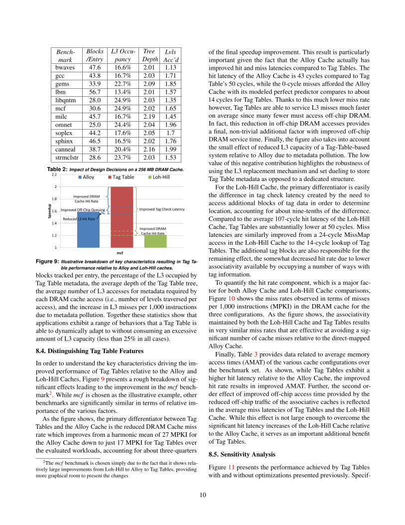
8.3. Overall Results
Figure 8 presents the speedups achieved by system configu-rations with either the Tag Table, Alloy Cache, or Loh-HillCache managing a 256MB L4 DRAM cache relative to a base-line system that interfaces the 8MB L3 directly with mainmemory (i.e., no DRAM cache). Overall, this graph shows anaverage speedup of 56% for Tag Tables relative to the 41.5%achieved by the Alloy Cache and 10.6% for the Loh-HillCache. Further, it shows the L3 miss rates on the secondaryy-axis that both a baseline system achieves with full accessto the L3 and a Tag Table system achieves with metadatapollution in the L3, showing that the impact is not so great.Notably though, the miss rate increases can be seen to fre-quently track the workloads where Tag Tables achieve lesserspeedup relative to the Alloy Cahe, leading to the conclusionthat metadata pollution can be a non-trivial factor for someworkloads, causing them to access the DRAM cache morethan they otherwise would. As we will show later in Figure 10with the DRAM cache miss rates however, these L3 miss ratesare compensated for by substantially improved DRAM cachemiss rates.
In addition to providing the average depth of the tree asmentioned previously, Table 2 provides further high-level de-tails, summarizing many key metrics for evaluating Tag Tables.From left to right, these metrics are the average number of
9
Bench-mark
Blocks/Entry
L3 Occu-pancy
TreeDepth
LvlsAcc’d
bwaves 47.6 16.6% 2.01 1.13gcc 43.8 16.7% 2.03 1.71gems 33.9 22.7% 2.09 1.85lbm 56.7 13.4% 2.01 1.57libqntm 28.0 24.9% 2.03 1.35mcf 30.6 24.9% 2.02 1.65milc 45.7 16.7% 2.19 1.45omnet 25.0 24.4% 2.04 1.96soplex 44.2 17.6% 2.05 1.7sphinx 46.5 16.5% 2.02 1.76canneal 38.7 20.4% 2.16 1.99strmclstr 28.6 23.7% 2.03 1.53
Table 2: Impact of Design Decisions on a 256 MB DRAM Cache.
1
1.2
1.4
1.6
1.8
2
2.2
Speedup
mcf
Alloy Tag Table Loh-Hill
Improved Tag Check Latency
Improved DRAM
Cache Hit Rate
Improved DRAM
Cache Hit Rate
Improved Off-Chip Queuing
Reduced L3 Hit Rate
Figure 9: Illustrative breakdown of key characteristics resulting in Tag Ta-ble performance relative to Alloy and Loh-Hill caches.
blocks tracked per entry, the percentage of the L3 occupied byTag Table metadata, the average depth of the Tag Table tree,the average number of L3 accesses for metadata required byeach DRAM cache access (i.e., number of levels traversed peraccess), and the increase in L3 misses per 1,000 instructionsdue to metadata pollution. Together these statistics show thatapplications exhibit a range of behaviors that a Tag Table isable to dynamically adapt to without consuming an excessiveamount of L3 capacity (less than 25% in all cases).
8.4. Distinguishing Tag Table Features
In order to understand the key characteristics driving the im-proved performance of Tag Tables relative to the Alloy andLoh-Hill Caches, Figure 9 presents a rough breakdown of sig-nificant effects leading to the improvement in the mcf bench-mark2. While mcf is chosen as the illustrative example, otherbenchmarks are significantly similar in terms of relative im-portance of the various factors.
As the figure shows, the primary differentiator between TagTables and the Alloy Cache is the reduced DRAM Cache missrate which improves from a harmonic mean of 27 MPKI forthe Alloy Cache down to just 17 MPKI for Tag Tables overthe evaluated workloads, accounting for about three-quarters
2The mcf benchmark is chosen simply due to the fact that it shows rela-tively large improvements from Loh-Hill to Alloy to Tag Tables, providingmore graphical room to present the changes
of the final speedup improvement. This result is particularlyimportant given the fact that the Alloy Cache actually hasimproved hit and miss latencies compared to Tag Tables. Thehit latency of the Alloy Cache is 43 cycles compared to TagTable’s 50 cycles, while the 0-cycle misses afforded the AlloyCache with its modeled perfect predictor compares to about14 cycles for Tag Tables. Thanks to this much lower miss ratehowever, Tag Tables are able to service L3 misses much fasteron average since many fewer must access off-chip DRAM.In fact, this reduction in off-chip DRAM accesses providesa final, non-trivial additional factor with improved off-chipDRAM service time. Finally, the figure also takes into accountthe small effect of reduced L3 capacity of a Tag-Table-basedsystem relative to Alloy due to metadata pollution. The lowvalue of this negative contribution highlights the robustness ofusing the L3 replacement mechanism and set dueling to storeTag Table metadata as opposed to a dedicated structure.
For the Loh-Hill Cache, the primary differentiator is easilythe difference in tag check latency created by the need toaccess additional blocks of tag data in order to determinelocation, accounting for about nine-tenths of the difference.Compared to the average 107-cycle hit latency of the Loh-HillCache, Tag Tables are substantially lower at 50 cycles. Misslatencies are similarly improved from a 24-cycle MissMapaccess in the Loh-Hill Cache to the 14-cycle lookup of TagTables. The additional tag blocks are also responsible for theremaining effect, the somewhat decreased hit rate due to lowerassociativity available by occupying a number of ways withtag information.
To quantify the hit rate component, which is a major fac-tor for both Alloy Cache and Loh-Hill Cache comparisons,Figure 10 shows the miss rates observed in terms of missesper 1,000 instructions (MPKI) in the DRAM cache for thethree configurations. As the figure shows, the associativitymaintained by both the Loh-Hill Cache and Tag Tables resultsin very similar miss rates that are effective at avoiding a sig-nificant number of cache misses relative to the direct-mappedAlloy Cache.
Finally, Table 3 provides data related to average memoryaccess times (AMAT) of the various cache configurations overthe benchmark set. As shown, while Tag Tables exhibit ahigher hit latency relative to the Alloy Cache, the improvedhit rate results in improved AMAT. Further, the second or-der effect of improved off-chip access time provided by thereduced off-chip traffic of the associative caches is reflectedin the average miss latencies of Tag Tables and the Loh-HillCache. While this effect is not large enough to overcome thesignificant hit latency increases of the Loh-Hill Cache relativeto the Alloy Cache, it serves as an important additional benefitof Tag Tables.
8.5. Sensitivity Analysis
Figure 11 presents the performance achieved by Tag Tableswith and without optimizations presented previously. Specif-
10

Bench-mark
Loh-Hill Alloy Tag TablesHit Rate Miss Lat AMAT Hit Rate Miss Lat AMAT Hit Rate Miss Lat AMAT
canneal 58.1% 161.2 129.7 47.0% 185.9 118.2 65.0% 168.8 94.8strmclstr 36.6% 155.9 138.1 33.5% 176.5 131.5 39.4% 160.2 117.5bwaves 41.6% 139.6 126.1 35.5% 158.6 117.2 42.3% 122.7 91.8gcc 74.9% 186.9 127.1 60.7% 225.4 114.1 80.7% 237.3 88.3gems 46.1% 310.2 216.6 40.1% 322.9 210.2 54.4% 310.8 170.8lbm 58.1% 307.8 191.2 49.5% 338.8 191.9 68.7% 225.9 106.3libqntm 23.4% 176.6 160.3 20.0% 199.9 168.3 26.9% 184.0 148.1mcf 52.5% 171.3 137.5 52.8% 196.4 114.9 62.9% 174.6 97.6milc 20.9% 211.7 189.8 21.5% 232.7 191.6 24.2% 208.6 170.5omnet 98.4% 149.4 107.7 75.8% 168.1 72.5 98.8% 151.9 55.0soplex 59.9% 205.8 146.6 54.6% 251.6 137.1 61.2% 214.7 115.5sphinx 53.3% 169.8 136.3 57.0% 206.1 112.6 59.7% 178.9 103.6Average 52.0% 195.5 150.6 45.7% 221.9 140.0 56.4% 197.3 114.1
Table 3: Average Memory Access Times (AMAT). Hit Latencies: Loh-Hill 107 cycles, Alloy 42 cycles, Tag Tables between 49 and 54 cycles (dependent on numberof L3 lookups required for metadata - “Lvls Acc’d” in Table 2)
0
20
40
60
80
100
DR
AM
Cac
he
MP
KI
Benchmark
LohHill Alloy Tag Table
Figure 10: Miss Rates of Various Tag Tracking Mechanisms.
ically, these optimizations are 1.) the use of prefetching tomaintain no more than the maximum number of supportedchunks (Section 7.1) and 2.) the use of set dueling to se-lectively protect Tag Table metadata from being evicted byapplication data (Section 3.2). As the figure shows, the ma-jority of the benefit of Tag Tables is achieved with a simplesystem where the appropriate number of chunks (less thanfour for our evaluation) is maintained by evicting the shortestexisting chunk and where metadata is evicted without restraintby application data in the L3 cache. When selectively enablingthe optimizations however, it can be seen that certain appli-cations can be significantly affected. Specifically, omnetppexhibits a significant performance improvement when set duel-ing is enabled. As was the motivation for including metadataprotection, omnetpp exhibits excessive DRAM cache evictionsdue to L3 metadata evictions when not protected. By enablingset dueling, once it is observed that hit rates have degradedsufficiently in the non-protected sets versus the protected sets(by the Tag Table frequently missing on metadata accesses), a“low watermark” setting is enforced globally that prevents ap-plication data from evicting metadata below a certain threshold(four ways in our evaluation).
8.6. Prediction Opportunities
As alluded to previously, Tag Tables may benefit from previ-ously proposed prediction techniques, including the FooprintCache proposal (FPC), which maintains an associative tableof recently evicted sectors that records the subblocks that were
00.40.81.21.62
2.4
Spe
ed
up
Benchmark
Dueling Prefetching Baseline
Figure 11: Sensitivity Analysis of Tag Table Optimizations.
demanded during its last residence in the cache [9]. This tableis accessed on a miss using the PC and sector offset and isused to determine the set of blocks that are fetched into thesector. Figure 12 shows the potential benefit of prediction witha Footprint-Cache-like mechanism on our evaluated workloadsby mimicking a perfect prediction mechanism where all refer-enced blocks are fetched, as observed from a prior executiontrace. The figure presents the same prediction mechanismapplied to Tag Tables, using chunks as the sector analogy. Inother words, when a miss is encountered in the Tag Table, anumber of contiguous blocks are fetched that will be accessedprior to the eviction of the chunk. With a few exceptions, TagTables without a predictor outperforms the Footprint Cache de-sign, since it avoids the conflict misses caused by the sectoredorganization of the Footprint Cache tag array. FPC predic-tion shows great potential in many cases, though our results -which are based on workloads consistent with those evaluatedwith the Alloy Cache [14] - do not directly correlate with theworkloads used in the prior work on FPC [9]. CombiningFPC prediction with Tag Tables provides additional gains, andintegrates easily with the Tag Table organization; we leaveexploration of a detailed prediction scheme to future work.
9. Related WorkIn addition to the Alloy Cache, Loh-Hill Cache, and FootprintCache; TIMBER is another proposal - while presented as aDRAM cache inserted between the logic die and phase-changemain memory - that could similarly be adapted to tracking
11

0.81.01.21.41.61.82.02.22.42.62.8
Spe
ed
up
Benchmark
TT Ideal TT Null FP Ideal FP Null
Figure 12: Opportunity of Prediction on Footprint Cache and Tag Tables.Tag Tables without footprint fetch (TT null) and ideal footprintprefetch (TT ideal), and Footprint Cache without prefetch (FPnull) and with ideal prefetch (FP ideal).
tags for die-stacked DRAM or eDRAM caches [11]. TIMBERaugments tags-in-DRAM with an SRAM cache of recently-accessed DRAM cache blocks. On a hit to this small cache,the exact location of data is provided, as with Tag Tables. Ona TIMBER cache miss however, the DRAM cache must beaccessed to determine definitively whether or not the blockis present. In this way, it can outperform the MissMap forblocks with temporal locality at the expense of increasingmiss latency. Hit latency to blocks that miss the SRAM cacheis unaffected. Unlike Tag Tables, TIMBER’s cache does notprovide the full tag information in SRAM - limiting knowledgeto recently-accessed blocks - however it could potentially beadapted to avoid Tag Table walks by querying it first on anaccess, possibly improving the performance of applicationsthat exhibit temporal locality at the DRAM cache.
10. Conclusion
This paper proposes Tag Tables, a robust and dynamicallyadaptable solution to the tag tracking problem for large capac-ity caches with traditional block sizes that allows a system toutilize a large capacity DRAM cache to achieve an averagespeedup of greater than 58% for a range of multithreaded andmultiprogrammed workloads. Unlike previous proposals forsmall-block DRAM caches, Tag Tables are realizable with astorage requirement suitable for implementation on the speed-optimized SRAM logic die. This small storage footprint isaccomplished through the combination of the on-demand na-ture of a forward page table and compressed base-plus-offsetentry encoding. Relative to prior state-of-the-art approaches,Tag Tables outperform the Alloy Cache by 10% and the Loh-Hill Cache by 44%. In addition, we have presented initialinvestigation into the feasibility of incorporating the orthogo-nal footprint prediction method utilized to great effect in theFootprint Cache.
11. Acknowledgments
This work was supported in part by the National ScienceFoundation under grants CCF-1116450 and CCF-1318298and a gift from Qualcomm Research.
References[1] G. Anderson and J.-L. Baer, “Design and evaluation of a subblock
cache coherence protocol for bus-based multiprocessors,” Universityof Washington, Tech. Rep. UW CSE 94-05-02, 1994.
[2] J. Andrews and N. Baker, “Xbox 360 system architecture,” Micro,IEEE, vol. 26, no. 2, pp. 25–37, March 2006.
[3] K. Barr, H. Pan, M. Zhang, and K. Asanovic, “Accelerating multipro-cessor simulation with a memory timestamp record,” in PerformanceAnalysis of Systems and Software, 2005. ISPASS 2005. IEEE Interna-tional Symposium on, 2005, pp. 66–77.
[4] C. Bienia, “Benchmarking modern multiprocessors,” Ph.D. dissertation,Princeton University, January 2011.
[5] B. Black, M. Annavaram, N. Brekelbaum, J. DeVale, L. Jiang, G. Loh,D. McCauley, P. Morrow, D. Nelson, D. Pantuso, P. Reed, J. Rupley,S. Shankar, J. Shen, and C. Webb, “Die stacking (3d) microarchitec-ture,” in Microarchitecture, 2006. MICRO-39. 39th Annual IEEE/ACMInternational Symposium on. IEEE, 2006, pp. 469–479.
[6] T. E. Carlson, W. Heirman, and L. Eeckhout, “Sniper: exploring thelevel of abstraction for scalable and accurate parallel multi-core sim-ulation,” in Proceedings of 2011 International Conference for HighPerformance Computing, Networking, Storage and Analysis. ACM,2011, p. 52.
[7] Y. Chou, B. Fahs, and S. Abraham, “Microarchitecture optimizationsfor exploiting memory-level parallelism,” in Computer Architecture,2004. Proceedings. 31st Annual International Symposium on, 2004, pp.76–87.
[8] P. Hammarlund, A. J. Martinez, A. A. Bajwa, D. L. Hill, E. Hallnor,H. Jiang, M. Dixon, M. Derr, M. Hunsaker, R. Kumar, R. B. Osborne,R. Rajwar, R. Singhal, R. D’Sa, R. Chappell, S. Kaushik, S. Chennu-paty, S. Jourdan, S. Gunther, T. Piazza, and T. Burton, “Haswell: Thefourth-generation intel core processor,” Micro, IEEE, vol. 34, no. 2, pp.6–20, Mar 2014.
[9] D. Jevdjic, S. Volos, and B. Falsafi, “Die-stacked dram caches forservers: hit ratio, latency, or bandwidth? have it all with footprintcache,” in Proceedings of ISCA-40, 2013, pp. 404–415.
[10] G. H. Loh and M. D. Hill, “Efficiently enabling conventional blocksizes for very large die-stacked dram caches,” in Proceedings of the44th Annual IEEE/ACM International Symposium on Microarchitec-ture, ser. MICRO-44 ’11. New York, NY, USA: ACM, 2011, pp.454–464.
[11] J. Meza, J. Chang, H. Yoon, O. Mutlu, and P. Ranganathan, “Enablingefficient and scalable hybrid memories using fine-granularity dramcache management,” Computer Architecture Letters, vol. 11, no. 2, pp.61–64, July 2012.
[12] M. Ohmacht, D. Hoenicke, R. Haring, and A. Gara, “The edram basedl3-cache of the bluegene/l supercomputer processor node,” in ComputerArchitecture and High Performance Computing, 2004. SBAC-PAD2004. 16th Symposium on, Oct 2004, pp. 18–22.
[13] B. Pham, V. Vaidyanathan, A. Jaleel, and A. Bhattacharjee, “Colt:Coalesced large-reach tlbs,” in Proceedings of the 2012 45thAnnual IEEE/ACM International Symposium on Microarchitecture, ser.MICRO-45. Washington, DC, USA: IEEE Computer Society, 2012,pp. 258–269. Available: http://dx.doi.org/10.1109/MICRO.2012.32
[14] M. Qureshi and G. Loh, “Fundamental latency trade-off in architectingdram caches: Outperforming impractical sram-tags with a simple andpractical design,” in Microarchitecture (MICRO), 2012 45th AnnualIEEE/ACM International Symposium on, 2012, pp. 235–246.
[15] M. K. Qureshi, A. Jaleel, Y. N. Patt, S. C. Steely, and J. Emer, “Adaptiveinsertion policies for high performance caching,” in Proceedings of the34th annual international symposium on Computer architecture, ser.ISCA ’07. New York, NY, USA: ACM, 2007, pp. 381–391.
[16] P. Rosenfeld, E. Cooper-Balis, and B. Jacob, “Dramsim2: A cycleaccurate memory system simulator,” Computer Architecture Letters,vol. 10, no. 1, pp. 16 –19, jan.-june 2011.
[17] T. Sherwood, E. Perelman, G. Hamerly, and B. Calder, “Automati-cally characterizing large scale program behavior,” in ACM SIGARCHComputer Architecture News, vol. 30, no. 5. ACM, 2002, pp. 45–57.
[18] S. Thoziyoor, N. Muralimanohar, J. Ahn, and N. Jouppi, “Cacti 5.3,”HP Laboratories, Palo Alto, CA, 2008.
[19] E. Witchel, J. Cates, and K. Asanovic, “Mondrian memory protection,”SIGARCH Comput. Archit. News, vol. 30, no. 5, pp. 304–316, Oct.2002.
12