Tacheometric survey
64
SHREE SA’D VIDYA MANDAL INSTITUTE OF TECHNOLOGY DEPARTMENT OF CIVIL ENGINEERING
-
Upload
arvindsai-nair -
Category
Engineering
-
view
921 -
download
10
Transcript of Tacheometric survey

SHREE SA’D VIDYA MANDAL
INSTITUTE OF TECHNOLOGY
DEPARTMENT OF CIVIL
ENGINEERING
Subject:-Advanced Surveying
Topic:-Tacheometric Surveying

Presented by:-
Name
Arvindsai Nair
Dhaval Chavda
Nirmal Patel
Rupesh Patel
Saptak Raval
Enrollment no.
130454106002
130454106001
140453106009
140453106010
140453106015

Contents
Topics Slides
1. Tacheometric survey(intro)……….....05
2. Fixed hair method…………………..…06
3. Stadia constant…………………....……30
4. Movable hair method…………….........34
5. Tangential method……………………..39
6. Anallatic lens……………………….…...50
7. Subtense bar…………………………....53
8. Field work in tacheometric survey…57

Tacheometric survey
Tachometry is a method of measuring both
horizontal distance and vertical elevation of
a point in the distance, without the use of
sophisticated technology, such as electronic
distance measurement (EDM) or satellite
transmissions.

Fixed hair method

Fixed hair method• This is a method of finding the distance and elevation of staff from the theodolite (Tachometer).
•Different formulas are used in finding distance for different cases.
•Some cases are discussed as follows:-

Case 1 : When line of sight is
horizontal and staff is held
vertically.

Where,
A,B =Point on staff cut but upper and lower hair
a,b=upper and lower cross hair
ab=i=Stadia interval
AB=S= staff intercept
D=distance from axis of tachometer to staff
D=distance between optical center and axis of tachometer.

Proof:
From Similar triangle ABf and a’b’f
we get,
( f0=f ; AB=S;
a’b’=i)
Now total distance(D)=fC+f+d
+f+d

Now as i ,f and d are constants we can write that the total horizontal distance
i.e. D= K.S + C
where ,
K= =Multiplying constant
C=f+d= Additive constant
Here, vertical distance is zero.

Case 2: When line of sight is
inclined but staff is held
vertically.

C
A
O’
DO
A`
B
C`
P
P’
h
V
Ө
α
(a) Angle of elevation {+}
α
S
Line of axis

Horizontal distance (D)=
Formula for horizontal
distancecos.L
cos)cos.( CsKD
coscos. 2 CsKD

Vertical distance (V)=
Formula for vertical distance
sin2
2Sin . CsKV
sin)cos .( CsKV
sin.L

Reduced level of Q = Reduced level of
H.I. + V -h
Formula for elevation of staff
station

D
Line of
Axis
A
B
C’
C
V
h
P’
P
O
θ
O’
(b) Angle of Depression {-}

Horizontal distance (D)= L.
Formula for horizontal
distance
coscos2 CKSD
cos)cos( CKSD

sin2
2Sin S K. CV
Vertical distance (V)= L.
Formula for vertical distance
sincossin S K. CV

Reduced level of P = Reduced level of
H.I. -V -h
Formula for elevation of staff
station

Case 3: When line of sight is
inclined but staff is held normal
to the line of sight.

(a) Angle of elevation {+}
C
A
O’
DO
A`
B
C`
P
P’
h
V
Ө
αα
S
Line of axis
h c
os
θ
h sin θ
L cos θ

Horizontal distance (D)
Formula for horizontal
distance sincos. hL
sincos).( hCsK
sincoscos. hCsK

Vertical distance (V)
Formula for vertical distance
sinL
sin).( CsK
sinsin. CsK

Reduced level of Q = Reduced level of
H.I. + V -h
Formula for elevation of staff
station
cos

(b) Angle of Depression {-}
Line of
Axis
A
B
C
V
h cosθ
P P1
O
θO’
DL cos θ
L
h
sinθ

Horizontal distance (D)
Formula for horizontal
distance sincos. hL
sincos).( hCsK
sincoscos. hCsK

Vertical distance (V)
Formula for vertical distance
sinLsin).( CsK
sinsin. CsK

Reduced level of Q = Reduced level of
H.I. -V -h
Formula for elevation of staff
station
cos

STADIA CONSTANTS

STADIA CONSTANTS
Stadia or tacheometric constants are:-
1. Multiplying constant
where,
f =focal length of the
lens
i =stadia intercept
The value of multiplying constant is
generally 100.
i
fA

2. Additive constant
B=(f+d)
where,
f=focal length of the lens
d= horizontal distance between instrument axis to optical centre of a lens
The value of additive constant. varies from 0.15 m to 0.60 m.

In tachometric surveying, instrument used is known as a tachometer.
With the help of a tachometer observations (stadia readings and vertical angles) are taken and horizontal and vertical distances are determined by using formulae.
Before doing calculations we should known the values of two constants for a tachometer to be used for survey work.
Generally their values are mentioned in the catalogue supplied by the manufacturer.
Also the constants may be determined by:
1. Laboratory measurement
2. Field measurement

MOVABLE HAIR
METHOD
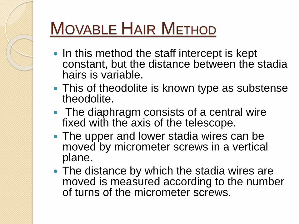
MOVABLE HAIR METHOD
In this method the staff intercept is kept constant, but the distance between the stadia hairs is variable.
This of theodolite is known type as substense theodolite.
The diaphragm consists of a central wire fixed with the axis of the telescope.
The upper and lower stadia wires can be moved by micrometer screws in a vertical plane.
The distance by which the stadia wires are moved is measured according to the number of turns of the micrometer screws.

Fig. A special type diaphragm of
a moving hair theodolite

The full turns are read on the graduated scale seen in the filed of view and the fractional part of a turn is of the read on the graduated drum micrometer screw placed one above and one below the eye piece.
The total distance through which stadia is the sum wires move, equal to of the micrometer readings.
If the distance between the instrument station and staff position is within 200 m, an ordinary leveling staff may be used and a full meter reading used for the purpose of observing a constant intercept.
For distances exceeding 200m it becomes

In such cases two vanes or targets fixed at a known distance apart on a staff, are observed.
A third target is fixed at the mid-point of the two targets.
For taking the observation, the middle target is first bisected by the central wire.
Then the micrometer screws are simultaneously turned to move the stadia wires until the upper and lower targets are bisected.
The readings are then noted.

Tangential Method

Tangential Method
No stadia hairs
Levelling staff with vanes or targets
at known distance
Horizontal and vertical distances are
measured by measuring the angles
of elevation or depression.
Some cases are discussed as
follows:-
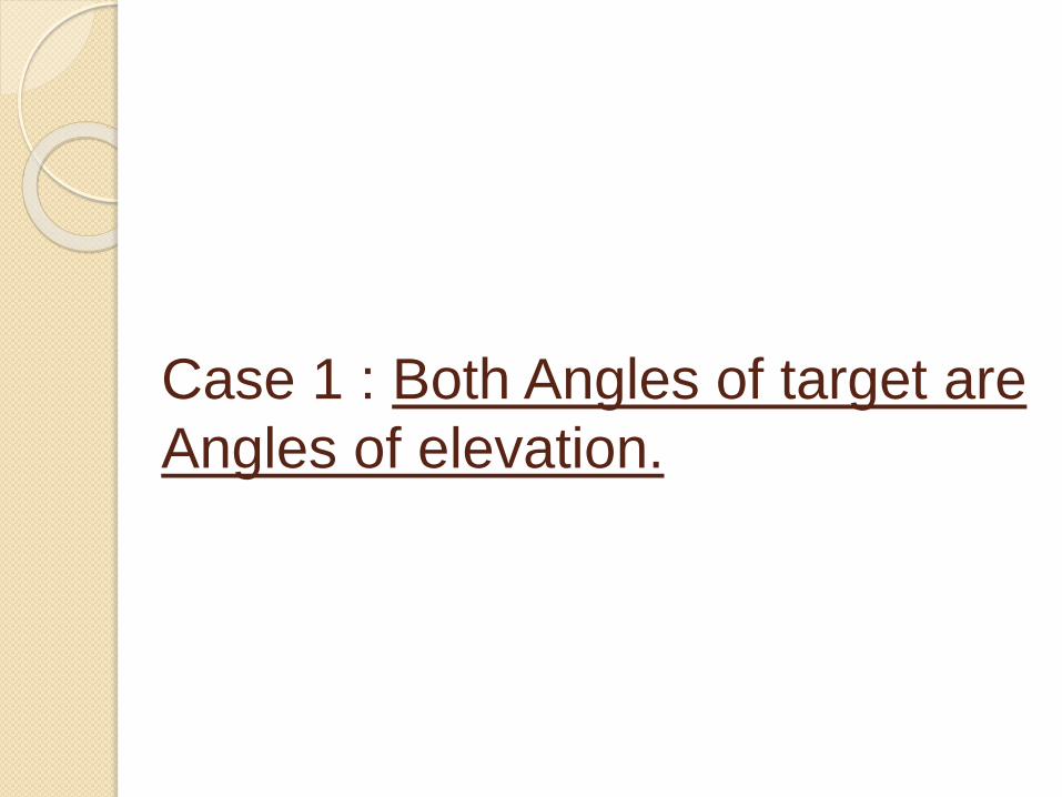
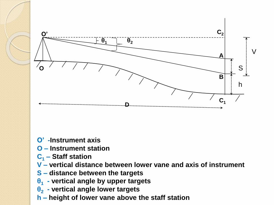
Case 1 : Both Angles of target are
Angles of elevation.
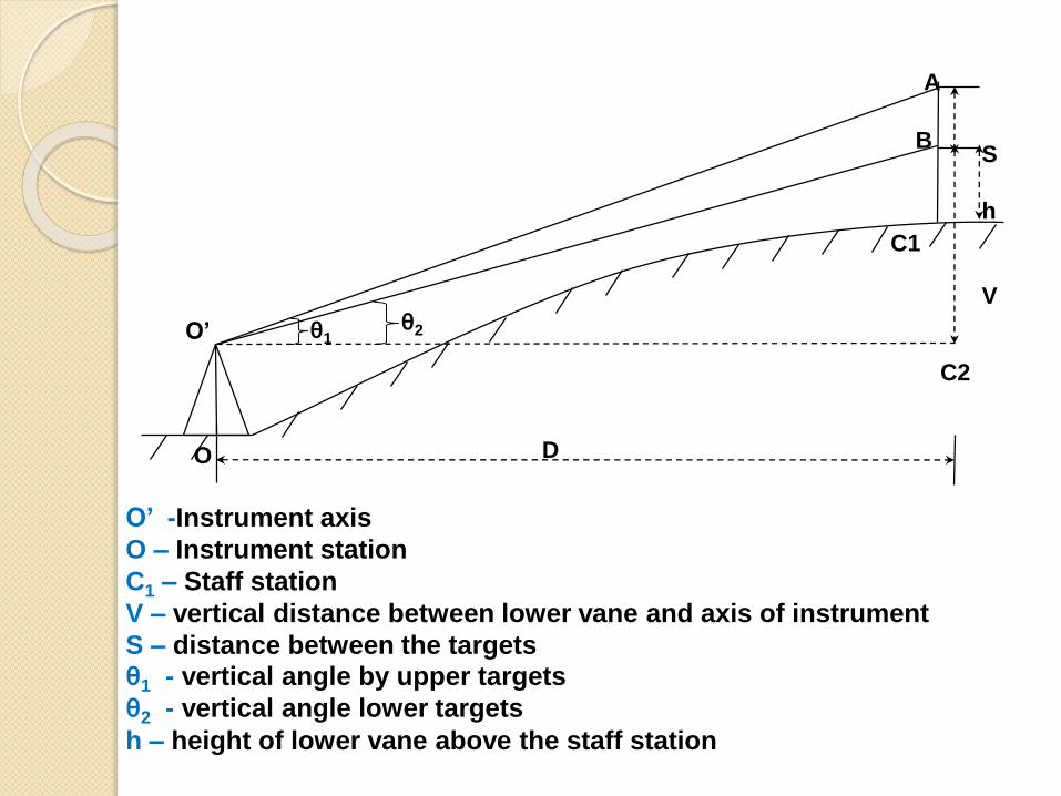
O’
O
S
h
V
B
A
D
C1
C2
θ2θ1
O’ -Instrument axis
O – Instrument station
C1 – Staff station
V – vertical distance between lower vane and axis of instrument
S – distance between the targets
θ1 - vertical angle by upper targets
θ2 - vertical angle lower targets
h – height of lower vane above the staff station

From figure we can say that,
Formula
21
2
21
21
2
1
tantan
tan
tantan
)tan(tan
tan
tan
SV
SD
DS
DV
DSV
RL of station C1 = RL of instrument axis + V - h

Case 2 : Both angles of target are
Angles of Depression
V
S
h
θ1 θ2
C2
A
B
C1
O’
O
D
O’ -Instrument axis
O – Instrument station
C1 – Staff station
V – vertical distance between lower vane and axis of instrument
S – distance between the targets
θ1 - vertical angle by upper targets
θ2 - vertical angle lower targets
h – height of lower vane above the staff station

From figure we can say that,
Formula
12
2
12
12
1
2
tantan
tan
tantan
)tan(tan
tan
tan
SV
SD
DS
DSV
DV
RL of station A = RL of instrument axis - V - h

Case 3 : One angle is angle of
elevation and the other is angle of
depression.

O’ -Instrument axis
O – Instrument station
C1 – Staff station
V – vertical distance between lower vane and axis of instrument
S – distance between the targets
θ1 - vertical angle by upper targets
θ2 - vertical angle lower targets
h – height of lower vane above the staff station
S
V
h
θ1
θ2
C2
C1
O’
O
D

From figure we can say that,
Formula
21
2
21
1
2
tantan
tan
tantan
tan
tan
SV
SD
DVS
DV
RL of station A = RL of instrument axis - V - h
Anallatic lens

Anallatic lens
• It is an additional lens generally provided in the
external focusing tachometer between object
glass & eyepiece
• Advantages of anallatic lens:-
1) For calculation of horizontal & vertical distances
constant (f+c)=0, if tacheometer is provided with
anallatic lens.
2) Calculation becomes simple.

Disadvantages of anallatic lens :-
1. The anallatic lens absorbs some of the
incident light which consequently results in reduction
of the brightness of the image.
2. It also adds to the initial cost of the instrument
because of one extra lens

SUBTENSE BAR

SUBTENSE BAR
The subtense bar is an instrument used for
measuring the horizontal distance between the
instrument station and a station where the
subtense bar is to be set up.
Substense method is an indirect method of
distance determination.
This method essentially consists of measuring the
angle subtended by two ends of a horizontal rod of
fixed length, called a subtense bar.
In this method a staff or target rod is not necessary,
and the theodolite required is also of the ordinary
transit type.

SUBTENSE BAR

The subtense bar is a metal bar of length varying from 3 to 4 m.
There are two discs of diameter about 20 cm at both ends of the bar.
The discs are painted black or red in front and white on the other side.
The alidade is made perpendicular to the axis of the bar.
A spirit level is included for levelling. The bar is mounted on a tripod stand which contains a ball and socket arrangement for levelling.

FIELD WORK IN
TACHEDMETRY1. Suitability:- A tacheometric survey is
conducted mainly for preparing a contour
map of a reservoir site, alignment of
highways or railways, canals etc. It is
also suitable for carrying out traverses
and filling in detail in rough and rugged
terrain where direct chaining is very
difficult. By means of a tacheometer the
relative distances and RLs of different
points can be computed from the
instrument station by taking observations
(vertical angles and staff readings).

2. Reconnaissance:- Before starting the
survey work the area to be surveyed is
thoroughly inspected examined) and
the instrument stations are selected
according to the nature of the area. If
the survey is conducted along a
narrow belt. the stations are selected
along the centre line of the belt fie.
alignments of highways,railways,
canals, etc)

Procedure:-
The tacheometric survey should be
conducted in the following steps:-
1. The tacheometer is set at station. It is
centred up the starting and levelled with
respect to the plat bubble and altitude
bubble.The height of the instrument
(HI) is measured by leveling staff or
stadia rod or tape. (i.e. height from
ground to centre of the trunnion axis).

2. Set-up horizontal and vertical vernier to
zero. Sight the staff held on the nearby
bench mark and observe the vertical
angle (for inclined sight, and the
readings of the three hairs on staff held
vertically bench mark. If there is no
bench mark nearby, fly levelling may
be done from any nearby BM. To
establish another one near the site area
to know the RL of the starting station.
3. The instrument is oriented with
reference to any pre-determined station
by taking its magnetic bearing and
consider it as first ray at 0.

4. To cover the area (details) from the station, rays at 15
or 30 intervals are extended from the station The
overlap of the rays from nearby stations should be 10
to 15.Also the extension of rays depends on the
topography of the area of the station. Staff positions
on these rays depend on the slope of the ground.
Sight all the representive points from the starting
station and first must be extended up to the whole
length of the ray traverse leg (1e, A to E) to know the
length of the line. Observe the vertical angle and the
staff readings at the three hairs at each staff position.
This way take observations all rays and complete
the station. Take fare sight the traverse a station and
observe the vertical angle and the staff readings the
three wires. Also measure the horizontal angle
between the two traverse legs . Close the work the
BM. before shining the instrument on second station
get the check.

5. Shifting the instrument and set up at the second station.
it is centered and leveled. Measure the height of
instrument. Take the first reading from the BM and then
orient the telescope the first ray.First ray must be extended
to its fun length from B to A Sight all the representative
points on the rays observe vertical angles and staff
readings, and complete the station. Take a for sight on the
third station and observe vertical angle and staff readings.
Also measure horizontal angle between the two traverse
legs. Same way close the the work on the BM. to get the
check. All readings are recorded in the tachometric book.
6. Proceed similarly at each of the successive stations and
all the traverse stations are connected and the necessary
observations for all the points are taken from each station
and recorded clearly in the book.

7. From the metric book, the distances of the points from
the instrument stations and their respective RLs are
calculated by using tachometric table.
8. Since each station is sighted twice, the two values for
the length and elevation are obtained. If they are within
the limits of accuracy, the average of the two values
may be taken and if not work should be repeated.
9. The traverse is plotted to any suitable scale. Rays are
drawn from each station. The points are marked on
these rays considering their horizontal distances from
the station and RLs of the respective written. Then lines
may points are the contour be drawn by the method of
interpolation or by approximate method. North-line is
plotted considering the magnetic bearing of the first
traverse line. This way field work is carried out and
contour map is prepared.