Table of Contents - University of...
35
Transcript of Table of Contents - University of...

CAMPUS INFRASTRUCTURE & SERVICES
CIS-Standard – Hydraulic Services Page 2 of 35 Revision No: 001 Issue Date: 16 August 2013
Table of Contents 1 Purpose ............................................................................................................................................ 4
2 Scope ............................................................................................................................................... 4
3 Glossary of Terms .......................................................................................................................... 4
4 Authorities & Responsibilities ....................................................................................................... 5
5 Technical Requirements ................................................................................................................ 55.1 Design and Documentation ...................................................................................................................... 5
5.1.1 Design Approach ................................................................................................................ 65.1.2 Design Inputs and Process ................................................................................................. 65.1.3 Engineering Process .......................................................................................................... 65.1.4 Equipment Selection and sizing ......................................................................................... 65.1.5 Future Allowances .............................................................................................................. 6
5.2 Domestic Cold Water Services ................................................................................................................. 75.2.1 General ............................................................................................................................... 75.2.2 Design and Installation Criteria .......................................................................................... 75.2.3 Water Segregation and Backflow Prevention ................................................................... 105.2.4 Water Metering ................................................................................................................. 125.2.5 Equipment and Materials .................................................................................................. 12
5.3 Domestic Hot Water Services ................................................................................................................. 145.3.1 General ............................................................................................................................. 145.3.2 Design and Installation Criteria ........................................................................................ 155.3.3 Equipment and Materials .................................................................................................. 16
5.4 Rainwater harvesting and Water Re-use ................................................................................................ 165.4.1 General ............................................................................................................................. 165.4.2 Design and Installation Criteria ........................................................................................ 165.4.3 Equipment and Materials .................................................................................................. 17
5.5 Sanitary Plumbing & Sewer Drainage .................................................................................................... 185.5.1 General ............................................................................................................................. 185.5.2 Design and Installation Criteria ........................................................................................ 185.5.3 Equipment and Materials .................................................................................................. 21
5.6 Stormwater and Subsoil Drainage .......................................................................................................... 215.6.1 General ............................................................................................................................. 215.6.2 Design and Installation Criteria ........................................................................................ 225.6.3 Equipment and Materials .................................................................................................. 23
5.7 Natural Gas Services .............................................................................................................................. 245.7.1 General ............................................................................................................................. 245.7.2 Design and Installation Criteria ........................................................................................ 255.7.3 Equipment and Materials .................................................................................................. 25
5.8 Sanitary Fixtures, Tapware and Associated Equipment ......................................................................... 265.8.1 General ............................................................................................................................. 265.8.2 Equipment and Materials .................................................................................................. 26
5.9 Pipework Labelling and Identification ..................................................................................................... 285.9.1 Below Ground Services .................................................................................................... 285.9.2 Above Ground Services .................................................................................................... 28
5.10 Pipework Installation ............................................................................................................................... 295.10.1 Below Ground Pipework ................................................................................................... 295.10.2 Above Ground Pipework ................................................................................................... 295.10.3 Pipe Supports and Fastening ........................................................................................... 295.10.4 Core Holes and Sleeves ................................................................................................... 305.10.5 Corrosion Protection and Finishes ................................................................................... 30
6 Commissioning ............................................................................................................................. 31

CAMPUS INFRASTRUCTURE & SERVICES
CIS-Standard – Hydraulic Services Page 3 of 35 Revision No: 001 Issue Date: 16 August 2013
7 Documentation & Records ........................................................................................................... 317.1 Design Documentation ........................................................................................................................... 317.2 Completion Documentation .................................................................................................................... 31
8 Operations ..................................................................................................................................... 328.1 Materials and Equipment Selection ........................................................................................................ 328.2 Service Access Requirements ................................................................................................................ 328.3 Redundant Equipment ............................................................................................................................ 338.4 Interruption to Hydraulic Services ........................................................................................................... 33
9 Authorisation of Variations .......................................................................................................... 33
10 Quality Control ........................................................................................................................... 3310.1 Design Standard Compliance ................................................................................................................. 3310.2 Design Standard Certification ................................................................................................................. 3410.3 Construction Compliance ....................................................................................................................... 3410.4 Acceptance ............................................................................................................................................. 34
11 References ................................................................................................................................. 34
12 Notes ........................................................................................................................................... 35
13 Document Amendment History ................................................................................................ 35
14 Attachments ............................................................................................................................... 35

CAMPUS INFRASTRUCTURE & SERVICES
CIS-Standard – Hydraulic Services Page 4 of 35 Revision No: 001 Issue Date: 16 August 2013
1 PURPOSE
The CIS Hydraulic Services Standard sets out the University of Sydney's minimum requirements for the design, construction and maintenance of plumbing, drainage, stormwater, water and gas services. It ensures new and refurbished systems are energy efficient, fit-for-purpose, made from durable good-quality materials, contain no or minimal environmentally harmful substances, and are cost efficient to operate and maintain. Applicable requirements documented in Workplace Health and Safety legislation, Disability Discrimination legislation, State Environmental Planning legislation, Commonwealth and State legislation, National Construction Codes (NCC), the Building Code of Australia (BCA) and Australian and New Zealand Standards (AS/NZS) are the minimum and mandatory compliance requirements. Where any ambiguity exists between this standard and the aforementioned mandatory requirements then:
a. the highest performance requirements must apply b. applicable requirements must follow this order of precedence:
I. Workplace Health and Safety legislation II. Disability Discrimination legislation
III. State Environmental Planning and Assessment legislation IV. All other Commonwealth and State legislation V. NCC and BCA VI. AS/NZS VII. This standard and other University standards
2 SCOPE
These standards describe the minimum requirements for the design, construction and maintenance of all hydraulic services throughout all buildings owned, operated and managed by the University of Sydney.
The standards apply to all planners, project managers, consultants, contractors, sub-contractors, tenants, managing agents and University staff involved in the design, construction and maintenance of existing, new and proposed University buildings and facilities. Additional more stringent requirements may apply on a project-specific basis dependent upon risk management and insurance requirements. 3 GLOSSARY OF TERMS
AUMS Advanced Utilities Monitoring System
BCA Building Code of Australia
BFPD Backflow Prevention Device
BMCS Building Management & Control System
CCTV Closed circuit television
CIS Campus Infrastructure Services

CAMPUS INFRASTRUCTURE & SERVICES
CIS-Standard – Hydraulic Services Page 5 of 35 Revision No: 001 Issue Date: 16 August 2013
DI De-Ionised
DICL Ductile Iron Cement Lined
DPI Department of Primary Industries
EPA NSW Environmental Protection Authority
EP&AR Environmental Planning & Assessment Regulation
HWU Hot Water Unit
NCC National Construction Code
PC Practical Completion
PC 1 Physical Containment Level 1
PC 2 Physical Containment Level 2
PC 3 Physical Containment Level 3
PC 4 Physical Containment Level 4
PUG Project User Group or Project Working Group
RAG Registered Air Gap
RO Reverse Osmosis
RPZD Reduced Pressure Zone Device
TMV Thermostatic Mixing Valve
USYD University of Sydney
WELS Water Efficiency Labeling and Standards
WSUD Water Sensitive Urban Design
4 AUTHORITIES & RESPONSIBILITIES
This standard is owned by CIS. It is approved and signed-off by the Director, CIS. The CIS Engineering and Sustainability Team are responsible for maintaining the standards and keeping it up-to-date. The Standard must be reviewed biennially. 5 TECHNICAL REQUIREMENTS
5.1 DESIGN AND DOCUMENTATION
CAMPUS INFRASTRUCTURE & SERVICES
CIS-Standard – Hydraulic Services Page 6 of 35 Revision No: 001 Issue Date: 16 August 2013
5.1.1 DESIGN APPROACH
The University expects consultants and contractors to provide designs that meet the project briefs. The following are priorities that consultants and contractors are aware of and consider in their designs:
• Provide environmental conditions that meet the project brief • Take a long term balanced view of capital costs, energy costs, maintenance costs and
longevity • As educational and research both progress at rapid rates, usage of buildings and areas within
buildings can change a number of times within the life of a building, systems must be designed to be adaptable for such changes
5.1.2 DESIGN INPUTS AND PROCESS
The University expects consultants and contractors to proactively inform, advise and contribute to the design process. In particular the following aspects:
• Building Physics - provide advice to the project team, including other design team members that would improve the inherent building performance, which may lead to reductions in both capital and energy costs.
• Planning and architecture – Provide advice on the appropriate location of plant rooms and reticulation strategy to assist in both the planning of the building and the facilitation of better maintenance in the future. Such advice must be provided in the early stage of the design and planning process so that this is taken into consideration of the architect’s design, such that it can be incorporated into his planning. Late advice will lead to poor location of plant and lack of maintenance access, thus a building of poor quality that will suffer from either poor or lack of maintenance and high operational costs to the University.
• The University of Sydney – Provide advice on the availability of options, assist in assessing the advantages and disadvantages, provide analysis of life cycle costs and life expectancies, offer recommendations and assist in making decisions.
5.1.3 ENGINEERING PROCESS
The University expects consultants and contractors to be fully qualified, experienced and capable of carrying out all engineering design, calculations, equipment selection and construction quality checks. 5.1.4 EQUIPMENT SELECTION AND SIZING
In selecting equipment, the University expects consultants and contractors to select products of proven and reliable quality, with reputable support and after sales service.
Products which are of closed systems and proprietary in nature, thus locking the University into exclusive dependence of one manufacturer must be avoided and only used if there are no other options.
In the sizing of equipment, the University expects consultants and contractors to follow good industry practice. 5.1.5 FUTURE ALLOWANCES
The provision of spare capacities for future must be considered for all projects. In making such considerations careful analysis of spare capacity against the application of diversity and the balance thereof must be considered.
CAMPUS INFRASTRUCTURE & SERVICES
CIS-Standard – Hydraulic Services Page 7 of 35 Revision No: 001 Issue Date: 16 August 2013
5.2 DOMESTIC COLD WATER SERVICES
5.2.1 GENERAL
The water supply network serving the University of Sydney is a complex arrangement of Sydney Water owned infrastructure and University owned infrastructure. During the design development phase of the project the consultant/contractor must determine the water supply demand requirements for the project and determine if the existing infrastructure is capable of meeting the project requirements.
The consultant/contractor must allow to investigate and obtain all available details of the existing infrastructure, including the location and survey of underground services, as required. Pressure/flow enquiries must be submitted to Sydney Water, as required for the project, and all fees and charges applicable for this information must be allowed for. Where the water supply asset is owned by the University of Sydney, network diagrams must be requested from CIS and testing of the water supply to obtain available pressure /flow details must be allowed for. Where new connections to the existing water supply infrastructure are required, the consultant/contractor must provide an application for connection to either Sydney Water or CIS, dependent upon which party owns the asset.
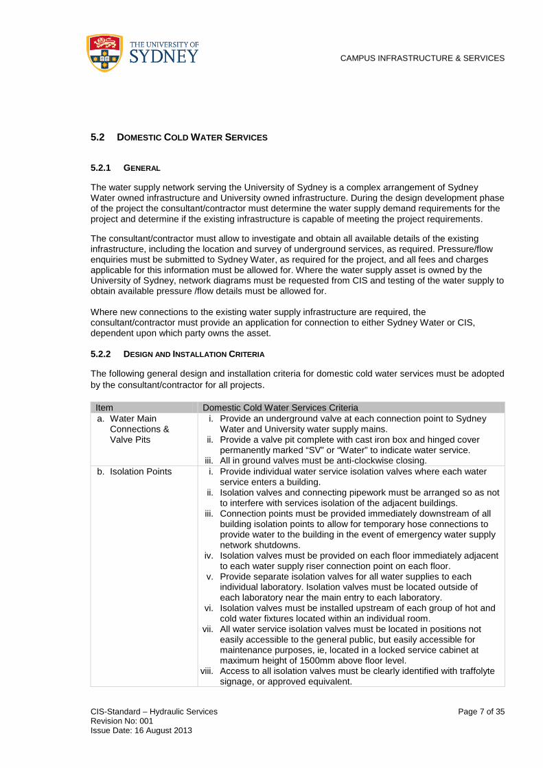
5.2.2 DESIGN AND INSTALLATION CRITERIA
The following general design and installation criteria for domestic cold water services must be adopted by the consultant/contractor for all projects.
Item Domestic Cold Water Services Criteria a. Water Main
Connections & Valve Pits
i. Provide an underground valve at each connection point to Sydney Water and University water supply mains.
ii. Provide a valve pit complete with cast iron box and hinged cover permanently marked “SV” or “Water” to indicate water service.
iii. All in ground valves must be anti-clockwise closing. b. Isolation Points i. Provide individual water service isolation valves where each water
service enters a building. ii. Isolation valves and connecting pipework must be arranged so as not
to interfere with services isolation of the adjacent buildings. iii. Connection points must be provided immediately downstream of all
building isolation points to allow for temporary hose connections to provide water to the building in the event of emergency water supply network shutdowns.
iv. Isolation valves must be provided on each floor immediately adjacent to each water supply riser connection point on each floor.
v. Provide separate isolation valves for all water supplies to each individual laboratory. Isolation valves must be located outside of each laboratory near the main entry to each laboratory.
vi. Isolation valves must be installed upstream of each group of hot and cold water fixtures located within an individual room.
vii. All water service isolation valves must be located in positions not easily accessible to the general public, but easily accessible for maintenance purposes, ie, located in a locked service cabinet at maximum height of 1500mm above floor level.
viii. Access to all isolation valves must be clearly identified with traffolyte signage, or approved equivalent.

CAMPUS INFRASTRUCTURE & SERVICES
CIS-Standard – Hydraulic Services Page 8 of 35 Revision No: 001 Issue Date: 16 August 2013
c. Water Filtration – Incoming Supply
i. Provide removable filtration to all main incoming supplies. ii. Filtration to be 20 microns.
d. Water Tanks i. Potable and non-potable water tanks must be 316 stainless steel modular panel type tanks.
ii. Panel tanks must be installed on raised supporting beams allowing access to visually inspect the underside of the base of the tank.
iii. A minimum clear distance of 500mm around each wall of the panel tank must be provided to allowance maintenance and inspection of the tank walls.
iv. Access ladders and lockable manhole covers to allow internal tank inspection and cleaning must be provided.
v. Tank water level indicators must be installed. vi. Tank filling valves must be Philmac servo type or approved equal. vii. Bladder or liner tanks will not be accepted.
e. Operating Pressure i. 250-600 kPa (for non fire fighting service) ii. Pressure reduction must be used to control maximum water
pressures f. Hot & Cold Water/
Pipeline Velocity i. Maximum 1.5 m/s
g. PH Correction i. Maintain pH between 6.5 and 7.5 where pH is required to be controlled.
h. DI and RO Water Filtration and Quality
i. PUGs must specify the quality and quantity of DI and RO water where required for laboratory usage.
ii. Proposed DI and RO water supply equipment must be submitted to CIS for approval complete with manufacturer’s maintenance requirements and budget costing over the life cycle of the equipment.
iii. DI and RO pipe systems must be provided with valving to allow individual floors to be shutdown without affecting the entire building.
iv. Pipework dead legs on DI and RO pipe systems will not be accepted. i. Backflow Prevention
Devices i. Each individual University building must be deemed a separate
property for the purposes of backflow prevention and must be installed with individual backflow prevention devices at the main water supply connection point to each building, in order to achieve building containment.
ii. RPZD valves must be installed to achieve site/building containment and zone containment. These high hazard backflow devices must be arranged to ensure that annual testing does not interrupt the water supply to the site/building/zone being served by the device.
iii. Zone and individual backflow prevention devices must be installed within each building to suit the relevant hazards contained.
iv. All backflow prevention devices must be located a maximum height of 1500mm above floor level.
j. TMVs i. Must be located in a lockable recessed stainless steel cabinet in readily accessible locations at a maximum height of 1500mm above floor level.
ii. Each TMV must be labelled with a traffolyte label stating valve number and room number(s) the device is supplying warm water to.
iii. Where installed to serve laboratories, must be located outside of each laboratory near the main entry to each laboratory.

CAMPUS INFRASTRUCTURE & SERVICES
CIS-Standard – Hydraulic Services Page 9 of 35 Revision No: 001 Issue Date: 16 August 2013
k. External Fire Hydrants
i. Connected to external water supply infrastructure only via a branch line.
ii. Must not be connected downstream of a building Brigade Booster Connection.
iii. Water supply to each external hydrant must be provided with sluice valve installed in a valve pit complete with cast iron box and hinged cover permanently marked “SV” or “Water” to indicate water service.
iv. Must be a twin hydrant arrangement. v. For more information refer to the Essential Fire Safety Measures
Standard. l. Boiling Water Units i. Filtered boiling water units must be provided in all designated tea
making areas. ii. Boiling water taps must be installed in the sink with the boiling water
unit installed in an accessible position in a cupboard directly below the sink.
m. Hose Taps i. Brass hose taps with a 20mm screwed outlet must be installed for cleaning purposes in open courtyards, external dining and entertaining areas.
ii. All plantrooms, chiller and cooling towers and accessible roof areas must be provided with brass hose taps with a 20mm screwed outlet to allow hose down and cleaning floors, roofs and gutters.
iii. Each bathroom must be provided with a chrome plated hose tap with a 15mm screwed outlet to allow placement of a cleaners bucket underneath (min 450mm above from FFL). A floor waste must be located directly below outlet of this tap where possible.
iv. Vacuum break devices must be installed to hose taps in zone protected areas and those installed in external areas.
v. Quarter turn taps are not permitted to be installed. vi. All hose taps must be provided with vandal proof spindles. vii. Backflow prevention must be installed on hose taps installed in
hazardous environments as necessary to comply with AS3500 and Sydney Water requirements.
n. Safety Showers / Eye Wash
i. All wet laboratories must be provided with emergency safety showers and eye wash facilities with a 25mm minimum potable cold water supply as per manufacturer’s instructions.
ii. Each safety shower/eye wash facility must be provided with an independent isolation valve.
iii. For more information refer to the Laboratory Standards.

CAMPUS INFRASTRUCTURE & SERVICES
CIS-Standard – Hydraulic Services Page 10 of 35 Revision No: 001 Issue Date: 16 August 2013
o. Urinals and Cisterns i. For all new and refurbished toilets, water supply pipework must be installed to facilitate the potential for future rainwater re-use and /or centralised grey water reticulation systems.
ii. This requires pipework serving urinal and cistern flushing systems to be installed independently of pipework serving hand basins, showers and other general drinking and potable water fixtures.
iii. In new buildings where rainwater re-use and/or grey water system is not proposed, this pipework must be installed throughout the facility and fed from the main hydraulic services plantroom containing metering, backflow prevention and/or pumping equipment for the potable water supply to the building.
iv. A pulse water meter must be installed on the urinal/cistern water supply pipework at the main connection point to the potable cold water supply.
v. In existing buildings, where this pipework is installed for future connection to a rainwater re-use and/or grey water system, the separated water supply pipework must be installed with a separate isolation valve provided on each floor immediately adjacent to each water supply riser connection point.
vi. Pipework installed to meet these requirements must be provided with approved lilac coloured continuous sleeving to indicate recycled water.
p. Flusherettes i. All urinals and toilets located in close proximity to high demand student and public areas must be supplied from a dedicated flusherette water supply system.
ii. Water supply pipework to the flusherette system must be fed from the main hydraulic services plantroom containing metering, backflow prevention and/or pumping equipment.
iii. A pulse water meter must be installed on the flusherette water supply pipework at the main connection point to the potable cold water supply.
iv. Water supplies to flusherette valves must only flow in a vertically downwards direction.
q. Building Management Control System (BMCS)/Advanced Utilities Monitoring System (AUMS)
The following water supply equipment must be connected and monitored by the BMCS/AUMS in real time:
i. All water supply pumps (potable/non-potable/rainwater re-use/hot water recirculating, etc) – run/fault alarms
ii. All tanks (potable/non-potable/rainwater re-use) – high and low level alarms
iii. Hot water plant – temperature/fault alarms iv. Water meters – consumption (maximum 15 minute increments) v. Rainwater re-use filtration plant
5.2.3 WATER SEGREGATION AND BACKFLOW PREVENTION
Existing buildings may contain a variety of water services, including potable, non-potable, de-ionised, reverse osmosis and rainwater re-use systems. The consultant/contractor is responsible for ensuring that the correct supply is provided to each fitting and fixture and to ensure that water supplies remain totally segregated.
Water segregation comprising separate potable and non-potable, cold and hot water supplies, must be provided within the following areas:
• Wet Laboratories - all types and ratings • Animal Houses

CAMPUS INFRASTRUCTURE & SERVICES
CIS-Standard – Hydraulic Services Page 11 of 35 Revision No: 001 Issue Date: 16 August 2013
All non-potable supplies including pipework and tapware must be clearly identified using standard pipe marking labels and tapware signage.
The following design and installation criteria for water segregation must be applied to all projects involving laboratories and animal houses:
Item Water Segregation Criteria a. Non-Potable Water
Supply i. Non-potable water supplies for all laboratory buildings must generally
be designed as centralised systems serving the entire building. ii. For new laboratory buildings, provision of a centralised non-potable
water supply via a registered break tank must be installed. iii. Non-potable mains pressure supplies will not be accepted. iv. In existing buildings containing laboratories, the consultant/contractor
must connect to the existing non-potable water supply serving the building.
b. Laboratory Water Supply (PC1, PC2, PC3 & PC4)
i. Separate supplies for potable cold water, potable hot water, non-potable cold water and non-potable hot water must be provided to each laboratory.
ii. Each supply must be provided with accessible isolation valves located outside of the laboratory facility to allow individual shutdown of each supply.
c. Laboratory Hot Water
i. Non-potable hot water supply to all laboratories must be independent from the potable hot water supply to the remainder of the building.
ii. The cold water supply inlet to any individual hot water unit serving a laboratory must be downstream of a backflow prevention device with a lockable valve to provide isolation and zone containment protection.
iii. Individual non-potable hot water units serving isolated laboratories must generally be quick recovery/instantaneous type. Where the size and/or the hot water demand of the laboratory does not permit the use of quick recovery/instantaneous HWUs, alternatives must be submitted for approval.
d. Laboratory Backflow Protection (PC2, PC3 & PC4)
i. Each individual laboratory rated as PC2 and above must be provided with 4 off individual RPZDs serving potable cold water, potable hot water, non-potable cold water & non-potable hot water.
ii. RPZDs must be installed in a stainless steel cabinet located outside of the PC rated area to enable servicing without entering the laboratory facility.
iii. The door to the cabinet containing the RPZDs must be fitted with a hinged and lockable glass or perspex viewing panel.
iv. The cabinet must be provided with a 50mm diameter drain at the base of the enclosure.
v. Pipework supplying each device must be labelled pipe markers indicating water service type,
vi. The cabinet must be provided with a traffolyte label indicating the lab name and room number(s) that the devices are protecting.
e. Laboratory Hand Basin
i. Supplied with potable cold water and potable warm water (hand washing).
f. Laboratory Benches
i. Supplied with non-potable cold and non-potable hot water supply (laboratory work and equipment).
g. Emergency Shower/Eye Wash Facilities
i. Supplied with potable cold water.

CAMPUS INFRASTRUCTURE & SERVICES
CIS-Standard – Hydraulic Services Page 12 of 35 Revision No: 001 Issue Date: 16 August 2013
h. Animal Houses i. Supplied with separate potable cold water supply through a cistern for animal drinking.
ii. Supplied with separate potable warm water supply. iii. Supplied with separate non-potable hot and non-potable cold water
supplies. 5.2.4 WATER METERING
Each building must be provided with its own Sydney Water meter and/or University owned sub-meter assembly. All meters must be rated for revenue billing in commercial applications in addition to being suitable for monitoring of complex distribution water supply networks. All meter and sub-meter assemblies installed must be “smart meter” type with multiple pulsed outputs for increased real time data to provide water management information. These meter assemblies must be compatible for connection to the BMCS/AUMS via a set of voltage free contacts. Meters must be suitable for measuring bulk flows of cold water, hot water and rainwater, dependent upon usage, and must be installed with an in-line strainer to protect the rotor. Sub-meter assemblies must be installed within the building to measure water supplies for the following systems/areas:
a. Cooling Towers/Evaporative Condensers b. Steam Boilers c. Centralised Potable Hot Water Systems d. Centralised Non-potable Water Systems e. Heating Hot Water Boilers f. Urinal & Cistern flushing systems (including flusherette systems) – where dedicated
pipework is installed. g. Rainwater Reuse Systems h. Backup Potable Supply to Rainwater Reuse System i. Irrigation Systems j. Spaces proposed for tenancy leasing agreements k. Any equipment that utilises more than 50kL of water a month
Where meter assemblies are connected directly to the Sydney Water network, the contractor must make application to and pay for all fees for Sydney Water to supply a new meter assembly. Water meters must be installed in fully accessible positions to allow for easy reading and servicing. Individual isolation valves must be provided for each water meter assembly. The consultant/contractor must coordinate the location, meter type and data output with other building services consultants/contractors to ensure the installed meters are fully compatible with the BMCS/AUMS and adequate communication network connection points have been provided.
5.2.5 EQUIPMENT AND MATERIALS
All materials supplied and installed must be approved by the local authority have the respective Australian Standard's mark and manufacturer's SAA licence number. All materials must be first quality and the best of their respective kinds. Second quality or inferior materials must be rejected. All costs associated with replacement of rejected materials must be the contractor's responsibility. The following materials must be specified and installed.

CAMPUS INFRASTRUCTURE & SERVICES
CIS-Standard – Hydraulic Services Page 13 of 35 Revision No: 001 Issue Date: 16 August 2013
Item Domestic Cold Water Services Equipment & Materials a. Pipework Above
Ground i. Copper Type B in accordance with AS 1432 (pipe) AS 3688 (fittings) ii. Stainless Steel 316 min 2mm in accordance with ASTM A269-02a /
BS EN 10312 iii. The use of non-metallic water supply pipe in above ground locations
will not be accepted without prior approval from CIS. b. Pipework Below
Ground i. The CIS Standard – Permit to Dig Form (CIS-ENG-F003) must be
submitted and approved by CIS prior to installing or repairing any pipework located below ground.
ii. Ductile Iron Cement Lined (DICL) in accordance with AS 2280 for pipes greater than or equal to 100mm diameter
iii. Copper Type B in accordance with AS 1432 (pipe) AS 3688 (fittings) for pipes less than 100mm diameter
iv. All metallic pipes installed underground must be installed in polyethylene greensleeve protection bag
v. Warning tape must be installed 150mm above all underground pipes vi. The use of non-metallic pipe in underground locations will not be
accepted without prior approval from CIS. c. Copper Tube
Joints i. 15% silver solder for chilled and hot water lines ii. 5% silver solder for other services iii. Minimum 6mm lapped joints iv.
v.
Where 20-50mm pipe has screwed joints, quality hemp with an approved jointing compound or Teflon tape suitable for water services must be used Brass/nylon compression fittings will not be accepted
d. Ductile Iron Cement Lined Pipe Joints
without prior approval from CIS.
i. Jointed with Tyton-Lok rubber ringed joints and ii. Anchored in accordance with local authority and manufacturer’s
instructions iii. Gibault joints must be cement lined /FBE coated long sleeve with
stainless steel rods, nuts and washers e. Stainless Steel
Pipe Joints i. Butt jointed, TIG welded and passivated after welding.
f. Unions i. Bronze heavy pattern three piece bull nose taper type ii. Where a tap connector type union is used it must be either type silver
soldered to the piece or a loose nut used in conjunction with a stop formed tube
g. Valves Above Ground
i. 25mm or less – brass or chrome plated stop cocks ii. 50mm or less – non-rising spindle pattern, with clockwise closing,
screwed type with a union fitted to the outlet side iii. 80mm or less – bronze flanged iv. 100mm or greater – flanged cast iron with bronze trim except where
installed for hot water reticulation in which case the valve construction must be flanged bronze
v. Must be located in easily accessible positions for ease of maintenance at a maximum height of 1500mm above the floor
vi. Lever operated ball or butterfly valves h. Valves Below
Ground i. Sluice Valves ii. Flanged body ends, bolted cover and fusion bonded epoxy coated iii. Resilient seated iv. Non-rising spindle pattern v. Class 16, working pressure 1600kpa vi. Fitted with key cap vii. Anti clockwise closing viii. Manufactured in accordance with AS 2638.1-2002
i. Tempering Valves i. RMC Heatguard type or approved equivalent

CAMPUS INFRASTRUCTURE & SERVICES
CIS-Standard – Hydraulic Services Page 14 of 35 Revision No: 001 Issue Date: 16 August 2013
j. Thermostatic Mixing Valves
i. TMV’s to be placed in a lockable stainless steel box, recessed and clear of obstructions.
ii. TMV’s must be located at a maximum height above floor of 1500mm and readily accessible for ease of maintenance or testing without the need to climb ladders or scaffolding.
iii. Provide a traffolyte label on the box cover indicating “Thermostatic Mixing Valve – this valve requires regular servicing by a qualified person”
iv. Enware Aquablend or approved equivalent k. Reduced Pressure
Zone Device (RPZD) Valves
i. Devices must be installed complete with unions of appropriate size on the inlet & outlet sides of device/s so that water supply can be isolated facilitating easy removal of device/s
ii. Devices must be supported so that inlet & outlet pipe work is not supporting devices
iii. Backflow devices requiring a drain line must be provided with a 50mm minimum connected drain line
iv. Up to and including 50mm diameter must be screwed type v. Greater than 50mm diameter must be flanged type vi. RPZD Valves to be Tyco Model RP-03 or approved equivalent
l. Double Check Valves
i. Fire services water supplies must be provided with a double check valve with a check bypass water meter prior to the booster valve assembly.
ii. Double check valves must be Tyco DCDA03 or approved equivalent m. Cold Water Pump
Sets i. High efficiency pumps with variable speed drives ii. A minimum dual pump system arrangement must be installed with a
duty and standby and auto changeover every 12 hours iii. Certified for potable water use to AS4020 iv. Supplied by a pump manufacturer as a complete packaged system
mounted on a base with manifold, valves and control panel v. Enable removal of one pump while the other is in operation vi. Monitored by BMCS vii. All cold water pumpsets must be Grundfos type, or approved
equivalent n. Flexible
Connections i. Braided stainless steel bellow type not less than 4 pipe diameters
long. ii. Installed on all pump suction and discharge connections. iii. Maximum deflection on each flexible connection must not exceed 5
degrees. o. Basin and Sink
Connections i. Mini cistern cocks and chrome plated cover plates for both hot and
cold connections must be located at the wall under each fixture ii. Exposed pipework must be chrome plated iii. Braided stainless steel flexible hoses must be used only when the
hose is concealed in joinery or the like.
5.3 DOMESTIC HOT WATER SERVICES
5.3.1 GENERAL
The consultant/contractor must ensure the most efficient hot water supply is designed and installed to suit the building operations and demand. Gas boosted solar hot water systems must be installed where sufficient northern roof solar access is available. Where solar access is not achievable, mains pressure gas fired hot water systems must be installed. Heat recovery from the mechanical plant must be considered wherever possible. Life cycle analysis and costing must be performed to determine the most viable hot water supply for each project.

CAMPUS INFRASTRUCTURE & SERVICES
CIS-Standard – Hydraulic Services Page 15 of 35 Revision No: 001 Issue Date: 16 August 2013
Heat pump systems and electric hot water units must only be used where the above listed options are not viable. These types of systems must be submitted to CIS for approval. Centralised recirculating hot water installations must be installed to ensure continuity of hot water supply temperatures at each outlet. Systems must be designed with multiple units to ensure efficiency and system redundancy is maintained. A minimum of 20% spare capacity above the maximum hot water demand must be provided for all centralised hot water installations.
Recirculating pumps must be thermostatically controlled to limit unnecessary operation. Duty and standby hot water pumps must be installed to allow system redundancy.
All hot water installations must comply with the energy efficiency measures listed in the National Construction Code and to suit the requirements of the University of Sydney Sustainability Framework document.
Heat and energy loss must be minimised by installing adequate insulation on all hot water supply pipework and by locating hot water units in the vicinity of areas with the greatest demand. All hot water units must be installed at floor level in accessible locations with sufficient space to enable maintenance and/or removal and replacement of each individual unit. Copper safe trays complete with drainage pipework must be installed under all hot water units. Overflow/relief valves to must discharge to tundishes connected directly to a drainage connection point, not to the copper safe tray.
5.3.2 DESIGN AND INSTALLATION CRITERIA
The following general design and installation criteria for domestic hot water services must be adopted by the consultant/contractor for all projects. Item Domestic Hot Water Services Criteria a. Potable Hot Water
Temperature i. 420
ii. 50C to disabled persons amenities
0
iii. 60C to general bathrooms & amenities
0
iv. 65C to kitchens
0
v. Bathrooms and amenities must have thermostatic mixing valves installed to ensure the water temperature supplied to all fixtures complies with all statutory and NSW Health requirements
C to wet laboratories
b. Hot water dead leg i. Maximum dead leg allowable is 10 metres. ii. Hot water trace heating tape must be installed on all non-circulating
dead legs which exceed 5 metres. c. Insulation i. All hot water pipes must be installed with extruded flexible closed cell
insulation in accordance with AS4426. ii. Insulation must generally be of the sealed tube or hard drawn pre-
lagged type. iii. Split and taped insulation or zippered/press type insulation is not
acceptable iv. Vapour barrier consisting of reinforced aluminium foil laminate must
cover the insulation material with a minimum overlap of 50mm at each longitudinal joint.
v. The insulation must be pulled around bends in one piece. Where this is not possible and at tees the insulation must be mitred and neatly taped with 50mm wide PVC tape of similar colour to the insulation.
vi. Wood blocks must be provided at each pipe bracket. vii. For hot water pipework installed in plantrooms or exposed to
weather, 0.5mm zinc annealed steel sheathing must be installed over the insulation in a single piece with a 40mm overlap. The lap must face down and must be secured by pop rivets at 100mm spacing’s.

CAMPUS INFRASTRUCTURE & SERVICES
CIS-Standard – Hydraulic Services Page 16 of 35 Revision No: 001 Issue Date: 16 August 2013
5.3.3 EQUIPMENT AND MATERIALS
All hot water plant and equipment installed must be suitable for commercial applications and must be provided with sufficient capacity and rating required to serve the system demand. Item Domestic Hot Water Services Equipment & Materials a. Hot Water Heaters i. Mains pressure hot water heaters and storage vessels must be
installed complete with all necessary stop, check, drain and pressure relief valves necessary to complete the installation
ii. All hot water units must be heavy duty suitable for commercial applications All
iii. All hot water units must Rheem type, or approved equivalent. b. Operating Pressure i. Maximum 350kPa c. Pressure Reducing
Valve i. Installed in the cold water supply pipework to each hot water heater ii. Set at 500kPa
d. Insulation i. Minimum 25mm thickness ii. Similar or equal to Thermotec or Aeroflex iii. Mineral wool or fibre glass insulation will not be accepted
e. i. 0.6mm copper sheet AS3500.4 Safe Trays f. Gas Flue Pipes i. Individual flue pipes must be installed to each hot water unit
ii. Each flue pipe must be terminated with a flue cowl g. Hot Water
Circulating Pumps i. Dual pump system must be installed with a duty and standby
arrangement and auto changeover every 12 hours ii. Certified for potable water use to AS4020 iii. Supplied by a pump manufacturer as a complete packaged system
mounted on a base with manifold, valves and control panel iv. Enable removal of one pump while the other is in operation v. Monitored by BMCS vi. All hot water circulating pumps must be Grundfos type, or approved
equivalent h. Pipework i. As per domestic cold water services
5.4 RAINWATER HARVESTING AND WATER RE-USE
5.4.1 GENERAL
For new buildings, a rainwater harvesting and water re-use system must be considered for installation to suit the requirements of the University of Sydney Sustainability Framework document
.
5.4.2 DESIGN AND INSTALLATION CRITERIA
Rainwater re-use systems must collect rainwater from building roofs only and store the water in a dedicated rainwater re-use tank separate to any Stormwater On-Site Detention (OSD) storage requirements. Stormwater collected from hard surfaces external to the building and water collected from sub-soil drainage must not be piped to the rainwater re-use tank. Fire system test water may be piped to the re-use tank. To reduce the possibility of contamination of the rainwater re-use tank, first flush systems must be installed on all rainwater re-use downpipes prior to entry to the tank. Access for maintenance must be provided to all first flush systems.
CAMPUS INFRASTRUCTURE & SERVICES
CIS-Standard – Hydraulic Services Page 17 of 35 Revision No: 001 Issue Date: 16 August 2013
Rainwater tanks must be suitably sized to suit the demand of the rainwater being re-used throughout the system, the size of the roof area use to capture rainwater and the Bureau of Meteorology rainfall statistics for the local area. Rainwater must be treated prior to re-use and piped to a dedicated rainwater re-use pipework system. The rainwater treatment plant must be an automated/timed system and must include filtration, chemical dosing, backwash and disinfection processes to ensure the quality of water supplied to the system complies with current NSW Health and all applicable guidelines, regulations and standards applicable for the treatment and re-use of water. Metering to measure the quantity of rainwater re-used must be installed. A potable cold water supply must be provided to the re-use system to accommodate periods of low rainfall. This supply must be backflow protected using RPZDs and sub-metered. The potable water supply must be piped and valved to allow the rainwater re-use tank and water treatment plant to be fully bypassed and served only by the domestic cold water supply. Prior to the rainwater re-use system being brought into service, the re-use tank must be thoroughly flushed out with clean water and fully sterilised. In addition to the University witnessing this process, the consultant/contractor must provide documentary evidence confirming the provision of this process. Internal access to rainwater storage tanks must be provided to allow for cleaning. Vehicle access must also be provided to allow the tank to be pumped out by a vacuum pump truck. The consultant/contractor must provide a risk assessment fully detailing the safety aspects to be applied when draining, accessing, pumping out and cleaning the rainwater tank. Rainwater re-use may be used for the following functions, subject to University approval:
a. Irrigation b. Urinal & Cistern Flushing c. Cooling Tower Water
5.4.3 EQUIPMENT AND MATERIALS
All equipment, materials and fixtures installed in rainwater harvesting and re-use applications must be approved for use in such systems. Item Rainwater Harvesting & Water Re-use Equipment & Materials a. Tank i. Rainwater re-use tanks must be 316 stainless steel modular panel
type tanks or reinforced concrete type tanks ii. Panel tanks must be installed on raised supporting beams allowing
access to visually inspect the underside of the base of the tank. iii. A minimum clear distance of 500mm around each wall of the panel
tank must be provided to allowance maintenance and inspection of the tank walls.
iv. Access ladders and lockable manhole covers to allow internal tank inspection and cleaning must be provided.
v. Tank water level indicators must be installed. vi. Tank filling valves must be Philmac servo type or approved equal. vii. Bladder or liner tanks will not be accepted

CAMPUS INFRASTRUCTURE & SERVICES
CIS-Standard – Hydraulic Services Page 18 of 35 Revision No: 001 Issue Date: 16 August 2013
b. Filtration Plant i. Supplied by a water filtration plant manufacturer as a complete automated system with backwash filtration, ultra violet sterilisation, chemical dosing, water quality analysis
ii. Proposed water filtration plant and equipment must be submitted to CIS for approval complete with manufacturer’s maintenance requirements and budget costing over the life cycle of the equipment.
iii. Monitored by the BMCS to provide appropriate alarms for equipment and water quality failure
c. Pipework i. As per domestic cold water services ii. Provided with an approved lilac coloured continuous plastic
sleeving 5.5 SANITARY PLUMBING & SEWER DRAINAGE
5.5.1 GENERAL
The sewer and trade waste drainage network serving the University of Sydney is a complex arrangement of Sydney Water owned infrastructure and University owned infrastructure. During the design development phase of the project the consultant/contractor must determine the sewer and trade waste demand requirements for the project and determine if the existing infrastructure is capable of meeting the project requirements. The consultant/contractor must allow to investigate and obtain all available details of the existing sewer and trade waste infrastructure applicable to the project, including the location and survey of underground services, dilution pits, silt arrestors, etc, as required. This includes obtaining details of the existing Sydney Water Trade Waste Agreement. Where new or modified connections to the existing sewer infrastructure are required for the project works, the consultant/contractor must provide an application for connection to either Sydney Water or CIS, dependent upon which party owns the asset. Where required, this must include an application to modify the existing Sydney Water Trade Waste Agreement to accommodate the revised discharge trade waste into the Sydney Water sewer. All sanitary and trade waste discharged to sewer must meet the requirements of Sydney Water.
5.5.2 DESIGN AND INSTALLATION CRITERIA
The following general design and installation criteria for sewer/trade waste/sanitary plumbing and drainage must be adopted by the consultant/contractor for all projects.
Item Sanitary Plumbing &Sewer Drainage Criteria

CAMPUS INFRASTRUCTURE & SERVICES
CIS-Standard – Hydraulic Services Page 19 of 35 Revision No: 001 Issue Date: 16 August 2013
a. Sewer/Trade Waste Manholes and Pits
i. Pits and inspection chambers must be constructed of precast or cast in situ concrete to suit Sydney Water requirements.
ii. Pits must be fitted with gas tight access covers compatible with gatic lifting keys, or approved equivalent.
iii. Pit covers must be of Class D rating wherever accessible to any vehicle movement and be permanently labelled “S” for sewer or “TW” for trade waste.
iv. Pit covers that accommodate infill paving are acceptable provided the edge of the frame and the cover are each a minimum of 5mm thick with the cast elements extending to the surface of the paving.
v. Covers that utilise edge plates attached to the cast lid to enclose infill paving as the interface between the cover and the frame are not acceptable.
vi. Access ladders must be provided where access to the pit or chamber is required for maintenance purposes
vii. Cover lifting keys must be provided. viii. Pits or manholes must be installed at each change in direction of all
sewer pipework. b. Sizing i. All toilet pans minimum 100mm
ii. The sanitary plumbing and drainage system must be sized in accordance AS3500, based on fixture loading units with a diversity factor.
c. Venting i. Modified venting system using relief, group and branch vents must be installed for combined soil and waste stacks.
ii. Air Admittance Valves (AAV’s) must not be installed on any sanitary drainage and trade waste drainage pipework.
d. Drainage Pipework i. All underground sewer and trade waste drainage must be of minimum nominal size of 100mm.
ii. All in ground drainage pipework must be provided with accessible clear-outs and/or pits/manholes to accommodate general maintenance.
iii. Connections between different materials must be mechanical bolted gland joints, using neoprene ring gaskets, or threaded connections.
iv. Flexible neoprene/rubber connections with worm drive clips must not be accepted.
v. For existing buildings, new pipe work material must match the existing pipe.
e. Stacks i. Pipework must be concealed in accessible plumbing ducts and ceiling spaces.
ii. Access panels to stacks must be adequately sized to enable maintenance to be performed within the shaft.
f. Floor Wastes i. Floor wastes must be installed in cleaners rooms, toilets, washrooms, showers, plantrooms and first aid rooms
ii. Floor waste grates must be 100mm minimum internal diameter with removable chrome plated brass grate.
iii. Floor waste gullies in toilet areas must not be charged from a hose cock.
g. Laboratory Floor Wastes
i. No open floor wastes are to be provided to rooms and areas classified as wet laboratories.

CAMPUS INFRASTRUCTURE & SERVICES
CIS-Standard – Hydraulic Services Page 20 of 35 Revision No: 001 Issue Date: 16 August 2013
h. Inspection Openings (I/Os) – i. At the connection to the Sydney Water sewer.
All I/Os must be minimum 100mm diameter and installed:
ii. At the connection to the University sewer infrastructure. iii. Externally adjacent to the building on each branch line entering the
building iv. At intervals not exceeding 30m v. On the downstream and upstream end where any existing drain
passes under a building vi. Where any new section of drain is connected to an existing drain
including a cut into the main line vii. At all junctions and all changes of direction viii. At the base of each stack ix. At each main connection point to the stack at each level of the
building x. Within each toilet at end of line
. i. i. Dedicated trade waste drainage must be provided for all commercial
and industrial activities as determined by Sydney Water, eg laboratories, food preparation areas, arts/ceramics studios, mechanical workshops, etc.
Trade Waste Drainage
ii. Existing infrastructure must be fully reviewed prior to increasing trade waste discharges to pre-treatment equipment
j. i. Minimum trade waste pre-treatment requirements are determined by Sydney Water. These include grease traps, dilution pits, basket arrestors, sediment pits and general purpose pits.
Trade Waste Pre-Treatment
ii. The consultant/contractor must determine with the project user group and stakeholders, the detail and quantity of the trade waste discharge in order to determine the size and type of trade waste pre-treatment required for the project.
iii. Additional pre-treatment may be required for specialised laboratories to enable laboratory certification to Office of Gene Technology Regulator (OGTR) requirements.
k.
Condensate Drainage
i. Separate condensate drainage pipework must be installed for each item of mechanical plant producing condensate.
ii. Installed with continuous fall to termination point. iii. Insulated and labelled to termination point. iv. Minimum 25mm diameter. v. Installed in an accessible position vi. vii. External landscape and hardstand areas must be terminated over a
gully
Termination points must be:
viii. Internal/roof areas must be terminated via a tundish of appropriate size, connected above the water seal of a waste trap and installed 50mm minimum above surcharge point e.g. basin/sink.
ix. For more information refer to the Mechanical Services Standard l. i. Hot water unit temperature and pressure relief valve termination
point must be via a tundish HWU Relief Valve Drainage
m. Building Management Control System (BMCS)
The following sanitary plumbing and drainage equipment must be connected and monitored by the BMCS in real time:
i. Sewerage Pumps – run/fault alarms ii. Sewerage Pit – high level alarm iii. Sewerage Treatment Plant

CAMPUS INFRASTRUCTURE & SERVICES
CIS-Standard – Hydraulic Services Page 21 of 35 Revision No: 001 Issue Date: 16 August 2013
5.5.3 EQUIPMENT AND MATERIALS
All equipment, materials and fixtures installed in sanitary plumbing and sewer drainage must where applicable, be approved for use by Sydney Water. Item Sanitary Plumbing & Sewer Drainage Equipment & Materials a. Gravity Sewer
Drainage Pipe Below Ground
i. The CIS Standard – Permit to Dig Form (CIS-ENG-F003) must be submitted and approved by CIS prior to installing or repairing any pipework located below ground.
ii. Best Environmental Practice (BEP) certified PVC in accordance with AS1260, AS2032 (pipe) & AS3789 (jointing)
iii. Vitrified Clay Pipes
b. Stacks installed external to a building
installed in accordance with AS 1741 and approved by Sydney Water
i. Copper Type B in accordance with AS 1432 (pipe) and AS 3688 (fittings)
c. Stacks serving toilet areas and internal to a building
i. Best Environmental Practice (BEP) certified PVC in accordance with AS1260, AS2032 (pipe) & AS3789 (jointing)
d. Stacks for
laboratories i. HDPE Pipe and Fittings in accordance with AS4401 (pipe) AS2033
(jointing) and manufacturer’s instruction ii. Jointed using butt welding, electric welding sleeves or socket
connections with plug in and expansion couplings iii. Geberit or approved equivalent
e. Pumped Drainage i. Pressure pipe suitable for proposed pressures f. Vent pipes installed
external to a building i. Copper Type D in accordance with AS1432 (pipe) and AS3688
(fittings) g. Clear outs/Flushing
Points i. PVC bolted trap screws with brass lid of appropriate size as per
manufacturer’s instructions h. Sewage Pumps i. Sewage pumps must be grinder type pumps installed in pits
ii. Dual pump system must be installed with a duty and standby arrangement and auto changeover every 12 hours
iii. Supplied by a pump manufacturer as a packaged system complete with control panel
iv. Enable removal of one pump while the other is in operation v. Guide rails and lifting devices must be installed in situ to allow the
easy removal of the pump from the pit and replacement vi. The pumps must be connected to the BMCS to provide monitoring of
the status of the pumps and to provide a high level alarm. vii. An alarm bell must operate on a fault and high level alarm. The alarm
bell must be located in a public area. viii. Sewage pumps and control panels must be Grundfos or approved
equivalent.
5.6 STORMWATER AND SUBSOIL DRAINAGE
5.6.1 GENERAL
The stormwater drainage network serving the University of Sydney is a complex arrangement of Sydney Water, Council, Roads & Maritime Services (RMS) and University owned infrastructure. During the design development phase of the project the consultant/contractor must determine the stormwater demand requirements for the project and determine if the existing infrastructure is capable of meeting the project requirements.

CAMPUS INFRASTRUCTURE & SERVICES
CIS-Standard – Hydraulic Services Page 22 of 35 Revision No: 001 Issue Date: 16 August 2013
The consultant/contractor must allow to investigate and obtain all available details of the existing stormwater infrastructure applicable to the project, including the location and survey of underground services, on site detention tanks, as required. Where new or modified connections to the existing stormwater infrastructure are required for the project works, the consultant/contractor must provide an application for connection to whichever party owns the asset. All stormwater and sub-soil discharges must comply with water quality and discharge rates, in accordance with Sydney Water, Council and NSW EPA requirements. WSUD principles must be considered for all new buildings and public domain redevelopments in accordance with the
University of Sydney Sustainability Framework document.
Overland flow paths and flood mitigation measures must be assessed and incorporated as part of all new developments.
Further requirements regarding roof drainage requirements can be obtained from the CIS Roofing and Guttering Standards. 5.6.2 DESIGN AND INSTALLATION CRITERIA
A combination of adequate drainage, tanking and waterproof membranes must be designed and installed to remove the possibility of stormwater and groundwater ingress to all buildings from roofs, gutters, balconies, planter boxes, overland flow paths and seepage. The following general design and installation criteria for stormwater and sub-soil drainage must be adopted by the consultant/contractor for all projects. Item Stormwater & Subsoil Drainage Criteria a. Stormwater, Roof &
Balcony Drainage i. Drainage pipework installed to Australian Rainfall & Runoff Guidelines
(AR&R) 1 in 100 year average recurrence storm event ii. Overflows suitable to relieve runoff from a 1 in 200 year average
recurrence storm event b. Stormwater
Manholes and Pits i. Pits and inspection chambers must be constructed of precast or cast
in situ concrete to suit Sydney Water requirements. ii. Pits must be fitted with gas tight access covers compatible with gatic
lifting keys, or approved equivalent. iii. Covers must be of Class D rating wherever accessible to any vehicle
movement and be permanently labelled “SW” for stormwater. ix. Pit covers that accommodate infill paving are acceptable provided
the edge of the frame and the cover are each a minimum of 5mm thick with the cast elements extending to the surface of the paving.
x. Covers that utilise edge plates attached to the cast lid to enclose infill paving as the interface between the cover and the frame are not acceptable.
iv. Access ladders must be provided where access to the pit or chamber is required for maintenance purposes
v. Cover lifting keys must be provided. vi. Pits or manholes must be installed at each change in direction of all
stormwater pipework.

CAMPUS INFRASTRUCTURE & SERVICES
CIS-Standard – Hydraulic Services Page 23 of 35 Revision No: 001 Issue Date: 16 August 2013
c. Drainage Pipework i. All underground stormwater drainage must be of minimum nominal size of 100mm.
ii. All roof plumbing must be oversized at least one and a half times the calculated size.
iii. All downpipes/elevated stormwater drainage must terminate over a sink stone or grated pit.
iv. All roof plumbing incorporating close coupling joints must be statically tested.
v. Inspection openings must be installed on or below any junction or bend greater than 850
vi. Internal downpipes are not recommended. If internal downpipes are to be designed, failsafe components must be submitted to the CIS for approval.
.
d. Syphonic Drainage Syphonic drainage will generally not be accepted. Where proposed: i. Syphonic drainage can only be considered on flat roofs with
adequate rainheads ii. Syphonic drainage systems must be designed, installed,
commissioned and certified by an approved specialist syphonic drainage contractor, similar or equivalent to Syfon Systems.
iii. Syphonic rainwater outlets must be made of robust materials, suitable for the installed location.
iv. Outlets must incorporate leaf guards to restrict the entry of debris into the system without restricting the flow.
v. Proposed syphonic drainage system must be submitted to CIS for approval complete with manufacturer’s warranty and maintenance requirements and budget costing over the life cycle of the equipment.
e. i. Subsoil Drainage
f.
Installed on geotextile fabric with 150mm surround of 25mm blue metal aggregate.
i. Inspection Openings (I/O’s)
I/O’s must be provided at every junction, bend, change of direction and at the base of all downpipes.
5.6.3 EQUIPMENT AND MATERIALS
All equipment and materials installed in stormwater and sub-soil drainage must where applicable, be approved for use by Sydney Water. Item Stormwater and Subsoil Drainage Equipment & Materials a. Stormwater
Drainage Pipework Below Ground
i. The CIS Standard – Permit to Dig Form (CIS-ENG-F003) must be submitted and approved by CIS prior to installing or repairing any pipework located below ground.
ii.
iii.
Precast Reinforced Concrete Pipes – Class 4 with rubber ring joints in accordance with AS1342
b. Internal Gravity Stormwater Downpipes
Fibre Reinforced Cement Pipe (FRC) – Class 4 with rubber ring joints to suit AS4139, and AS3725
i. Best Environmental Practice (BEP) certified PVC in accordance with AS1260, AS2032 (pipe) & AS3789 (jointing)
c. External Gravity Stormwater Downpipes
i. Copper Type D in accordance with AS1432 (pipe) and AS3688 (fittings)
d. Syphonic Drainage Pipework
i. HDPE Pipe and Fittings in accordance with AS4130 (pipe) AS2033 (jointing) and manufacturer’s instruction
ii. Jointed using butt welding, electric welding sleeves or socket connections with plug in and expansion couplings
iii. All pipe and fittings must be verified by the approved specialist syphonic drainage contractor

CAMPUS INFRASTRUCTURE & SERVICES
CIS-Standard – Hydraulic Services Page 24 of 35 Revision No: 001 Issue Date: 16 August 2013
e. Subsoil Drainage Pipework
i. Factory slotted HDPE similar or equal to Vinidex Draincoil ii. Joined with solvent cement joints
f. Pumped Drainage i. Pressure pipe suitable for proposed pressures g. Inground Stormwater
Structures i. Stormwater pits, kerb entry pits, sumps and grated drains must be
precast or cast in situ concrete. ii. Access ladders must be provided where access to the pit or chamber
is required for maintenance purposes iii. Frames, covers and gratings for pits, sumps and drains must be
provided to suit Class D duties. iv. Cover lifting keys must be provided.
h. Subsoil Pumps i. Subsoil pumps must be submersible type installed in pits ii. Dual pump system must be installed with a duty and standby
arrangement and auto changeover every 12 hours iii. Supplied by a pump manufacturer as a packaged system complete
with control panel iv. Enable removal of one pump while the other is in operation v. Guide rails and lifting devices must be installed in situ to allow the
easy removal of the pump from the pit and replacement vi. The pumps must be connected to the BMCS to provide monitoring of
the status of the pumps and to provide a high level alarm. vii. An alarm bell must operate on a fault and high level alarm. The alarm
bell must be located in a public area. viii. Subsoil pumps and control panels must be Grundfos or approved
equivalent. i. Grated Drains i. Made of robust materials suitable for the installed location
ii. Grating sizes and materials must be assessed to maximise drainage potential but eliminate WHS issues relating to slips, trips and falls.
iii. Grates must be fixed in position to reduce potential vandalism but must enable easy removal via a key or tool to allow maintenance and replacement.
5.7 NATURAL GAS SERVICES
5.7.1 GENERAL
The gas supply network serving the University of Sydney is a complex arrangement of Jemena owned infrastructure and University owned infrastructure. During the design development phase of the project the consultant/contractor must determine the gas supply demand requirements for the project and determine if the existing infrastructure is capable of meeting the project requirements
The consultant/contractor must allow to investigate and obtain all available details of the existing infrastructure, including the location and survey of underground services, as required. Gas supply enquiries must be submitted to the University, Jemena and the University gas retailer, as required for the project, and all fees and charges applicable for this information must be allowed for. Where new connections to the existing gas supply infrastructure are required, the consultant/contractor must confirm details of the proposed consumption for all gas appliances being installed under the project works in conjunction with assessing the metering pressure available. These details must be submitted to Jemena and the University to ensure the incoming gas service, meter/sub-meter and regulator assembly is capable of providing the required consumption. Where new gas regulators, gas meters or sub-meter assemblies are required to be installed under the project, the consultant/contractor must pay all costs associated with the supply and installation of the equipment as required for the project works.

CAMPUS INFRASTRUCTURE & SERVICES
CIS-Standard – Hydraulic Services Page 25 of 35 Revision No: 001 Issue Date: 16 August 2013
5.7.2 DESIGN AND INSTALLATION CRITERIA
The natural gas service must be designed and installed to suit the requirements of AGL and Jemena. The following general design and installation criteria for natural gas services must be adopted by the consultant/contractor for all projects. Item Natural Gas Services Criteria a. Gas Pressure i. High and medium pressure gas supply must not be installed
internally within a building without prior approval from CIS. ii. Under and over pressure shut off regulators must be installed to suit
Jemena requirements to reduce high pressure to low pressure gas supplies.
iii. Vent pipes from gas regulators must be installed and terminated in locations approved by Jemena.
b. Gas Supply Metering i. High and medium pressure gas metering assemblies must be installed externally to the building in accordance with Jemena requirements.
ii. Each building must have its own University low pressure gas sub-meter assembly complete with data logger.
iii. Connection to the BCMS/AUMS system for all gas metering is to be provided
c. Service Isolation i. Provide individual gas service isolation points that enable isolation of each gas supply to each building.
ii. Isolation points must not interfere with the provision of gas services to adjoining buildings
d. Laboratory Isolation i. Provide isolation valves for all gas supplies to each laboratory. ii. Isolation points are to be located at the entry to the laboratory and be
clearly labelled. e. Purging i. All gas pipework must be purged with nitrogen in accordance with
the Authorities requirements f. Gas Heaters &
Cookers i. All heaters and cookers must be flued to the outside of building.
g. Cooktops i.
ii.
Gas cookers are approved to be installed in commercial kitchen facilities only.
Gas cookers installed in student housing and kitchenettes must not be accepted.
5.7.3 EQUIPMENT AND MATERIALS
All equipment and materials installed in natural gas systems must where applicable, be approved for use by AGL and Jemena. Item Natural Gas Equipment & Materials a. Pipework Above
Ground i. Copper Type B in accordance with AS 1432 (pipe) AS 3688
(fittings) ii. The use of non-metallic gas supply pipe in above ground locations
will not be accepted. b. Pipework Below
Ground i. The CIS Standard – Permit to Dig Form (CIS-ENG-F003) must be
submitted and approved by CIS prior to installing or repairing any pipework located below ground.
ii. To suit pressure and service in accordance with AS 5601-2010 and Jemena Network Operating Rules

CAMPUS INFRASTRUCTURE & SERVICES
CIS-Standard – Hydraulic Services Page 26 of 35 Revision No: 001 Issue Date: 16 August 2013
c. Jointing i. High Pressure 15% silver solder ii. Medium-Low Pressure 5% silver solder iii. Minimum 6 mm lapped joints. iv.
v.
Where 20-50mm pipe has screwed joints Teflon tape suitable for gas services must be used Brass/nylon compression fittings will not be accepted
d. Exposed Pipework Valves and Fittings
. i. Must be chrome plated wherever they are exposed outside of plant
areas. e. Gas Valves i. Spherical ball type in accordance with AS4617
ii. Up to and including 50mm diameter must be screwed type iii. Above 50mm diameter must be flanged type
f. Flues i. Stainless steel flue pipes must be installed to all gas appliances with flues
ii. Flue cowls must be installed to all flues
5.8 SANITARY FIXTURES, TAPWARE AND ASSOCIATED EQUIPMENT
5.8.1 GENERAL
All sanitary fixtures and tapware installed must incorporate a high level of water efficiency. Water saving devices must include aerated tap fittings, water flow restriction devices, dual flush toilets, low flush urinals and high efficiency showerheads. Fixtures and tapware installed must be low maintenance with a design life expectancy of 15 years. All fixtures, tapware and appliances are to have the Watermark approved certification and be provided with full product support, including spare parts and technical assistance, within the Sydney area.
5.8.2 EQUIPMENT AND MATERIALS
All materials must be first quality and the best of their respective kinds. Second quality or inferior materials must be rejected. All costs associated with replacement of rejected materials must be the contractor's responsibility. The following materials must be specified and installed. Item Sanitary Fixtures, Tapware and Associated Equipment and Materials a. Toilet Suites
(Cistern, Pan & Seat)
i. Close-coupled or wall faced design with exposed cistern ii. 4.5/3 litre dual flush system with a minimum WELS 4 Star Rating iii. Cisterns must be fitted with a vandal resistant conversion kit allowing
the lid to be locked onto the cistern iv. Compliant for use with rainwater re-use systems. v. White in colour. vi. Seat must be vandal resistant vii. Similar or equal to Caroma Caravelle 2000
b. Accessible Toilet Suite (Cistern, Pan and Seat)
i. Dual flush and have a minimum WELS 4 Star Rating ii. Compliant for use with rainwater re-use systems iii. White in colour. iv. Compliant with AS 1428.1 v. Similar or equal to Caroma Care 400

CAMPUS INFRASTRUCTURE & SERVICES
CIS-Standard – Hydraulic Services Page 27 of 35 Revision No: 001 Issue Date: 16 August 2013
c. Squat Toilets i. A proportion of squat toilets must be considered for installation in all major student/public toilet facilities.
ii. Squat toilets must be commercial quality iii. In-ground pans must be installed complete with anti slip sides and
distinct contoured footrests. iv. Minimum WELS 4 Star Rating with 4.5 litre flush
d. Urinal Suite i. Minimum WELS 3 Star Rating ii. Smart demand urine sensing flushing system or push button flush
activation iii. Where sensor flushing controls and power supply units are located
within walls or inaccessible ducts, a screwed stainless steel panel must be provided adjacent to the urinal to enable access for maintenance and replacement
iv. Compliant for use with rainwater re-use systems v. White in colour vi. Ceramic in material vii. Waterless urinals will not be accepted viii. Similar or equal to Caroma Cube 0.8L Electronic Activation or
Caroma Cube Urinal e. Concealed Cisterns i. Where concealed cisterns are proposed to be installed within walls
or inaccessible ducts, a screwed stainless steel panel (min 400mm x 400mm) must be provided above the pan or urinal to enable direct access to the cistern for maintenance and replacement
ii. Cisterns must not be mounted in ceiling spaces f. Flusherette Valves i. 4.5/3 litre dual flush system with a minimum WELS 4 Star Rating
ii. Where flusherette valves are proposed to be installed within walls or inaccessible ducts, a screwed stainless steel panel (min 400mm x 400mm) must be provided above the pan or urinal to enable direct access to the valve for maintenance and replacement.
iii. Similar or equal to Pubco concealed dual flush valve g. Basins i. Single taphole
ii. Ceramic in material iii. Overflow as standard
h. Accessible Basins i. Refer to basins details above ii. Compliant with AS 1428.1
i. Cleaners Sink i. Ceramic in material ii. Nominal size of 575mm x 435mm iii. Fitted with heavy chrome plated brass hinged grating iv. Installed directly below wall mounted hot and cold taps v. Similar or equal to Caroma Cleaners Sink
j. Tapware
i. Minimum WELS 5 Star Rating ii. Water outlets must be of the aerated type iii. Valves are to be of jumper type iv. Bright chrome plated only v. In high use public/student use areas, cold water push button timed
operation tapware must be installed to all basins vi. In staff areas hot and cold water must be supplied via mixer tapware
to all basins, kitchens and tea making facilities vii. Electronic sensor taps will not be accepted viii. Closing ceramic disc cartridge type tapware will not be accepted ix. All tapware must be manufactured in Australia
k. Accessible Tapware i. Refer to tapware details above ii. Compliant with AS 1428.1

CAMPUS INFRASTRUCTURE & SERVICES
CIS-Standard – Hydraulic Services Page 28 of 35 Revision No: 001 Issue Date: 16 August 2013
l. Shower Facilities i. 6l/min with a minimum WELS 3 Star Rating ii. Shower facilities must be provided for each building greater than
10002
iii. The number of shower facilities provided must be on a sliding scale determined by the number of bicycle storage facilities required under statutory planning regulations and the University of Sydney Sustainability Framework document.
m GFA.
m. Laboratory Sinks i. Stainless steel 316 acid resistant. ii. The university Project Manager to liaise with client on plug and waste
needs n. Laboratory Tapware All laboratory basins and sinks are to be provided with:
i. Lever/elbow action tapware for hot and cold water supplies ii. Electronic sensor taps will not be accepted iii. All laboratory tapware must be Enware, or approved equivalent
o. Safety Showers/Eye Wash
i. Combined hand operated stainless steel safety shower/eyewash facilities must generally be installed.
ii. All combined safety shower/eyewash facilities must be complete with an adequately sized and positioned bowl to capture and drain the water when the eyewash is in use.
iii. Where laboratory layouts do not allow combined safety shower/eyewash to be installed, an adequately sized handwash basin must be installed under the eyewash to capture the water when in use.
iv. A recessed stop valve must be provided to each safety shower/eyewash facility to enable isolation of the individual unit without affecting the potable water supply to other fixtures.
v. All safety shower/eye wash systems must be Enware, or approved equivalent
p. Combined Boiling/ Filtered Ambient Water Units
i. Each kitchen/tea making facility must be provided with a combined boiling/filtered ambient water unit.
ii. The tap supplying the boiling/filtered water must be located over a sink.
iii. The under sink control cabinet must be located within one metre of the tap, it must be adequately ventilated and provided with sufficient clearance around all sides of the cabinet.
iv. All boiling/filtered ambient water units must be similar or equal to ZIP Hydrotap model 1532.
q. Dishwashing and Washing Machines
i. Minimum WELS 5 Star Rating ii. Have anti flood technology in order to prevent water damage of
premises
5.9 PIPEWORK LABELLING AND IDENTIFICATION
5.9.1 BELOW GROUND SERVICES
All underground services to have marking tape of correct distances above pipework complying with relevant Australian Standards for that service. Where the service is non-metallic, provide a tape incorporating locating wire. 5.9.2 ABOVE GROUND SERVICES
All pipework must be labelled with adhesive pipe markers indicating pipe contents or system type and directional arrows indicating flow. Markers must be installed at a minimum of every five metres. Labelling must not be restricted only to close proximity of access panel openings.

CAMPUS INFRASTRUCTURE & SERVICES
CIS-Standard – Hydraulic Services Page 29 of 35 Revision No: 001 Issue Date: 16 August 2013
5.10 PIPEWORK INSTALLATION
5.10.1 BELOW GROUND PIPEWORK
All pipework and services installed below ground must be fully surveyed and documented in accordance with the details required for Quality Level A, as per AS5488-2013 – Classification of Subsurface Utility Information (SUI).
The CIS Standard – Permit to Dig Form (CIS-ENG-F003) must be submitted and approved by CIS prior to installing or repairing any pipework located below ground. For further details and requirements of all pipe installations below ground, please refer to the CIS Trench Excavation and Backfilling Standard. 5.10.2 ABOVE GROUND PIPEWORK
All pipe work chased into masonry walls must not cross any movement joint and must be provided with sufficient insulation so that expansion and contraction can take place without damage to pipe work or to the surrounding element and its surface finish.
5.10.3 PIPE SUPPORTS AND FASTENING
• AS3500.1. Table 5.2 Spacing of Brackets and Clips Spacing of pipework supports must be installed to suit:
• AS3500.2 2003. Table 9.1 Maximum Spacing of Brackets, Clips and Hangers. • AS3500.4 Heated Water Services • every 2 metres for pipework greater than or equal to 100mm in diameter • located to separately support valves within pipework of 200mm or greater.
Inlet and outlet pipework serving pumps and other hydraulic equipment must not be used to support the equipment. All equipment must be adequately supported independently of the to the inlet and outlet pipework supports.
Materials for pipework supports must be as follows.
Item Support Type Channels Use purpose made galvanised mild steel channel equal to Unistrut or approved
equivalent, complete with purpose made fittings. Provide plastic end caps on exposed brackets.
Insulation Barrier Use purpose made wooden block barriers between steel clamps and copper / steel / uPVC pipes.
Fasteners Galvanised bolts, nuts and washers of adequate size,
Pipe Hangers rod diameters must be as follows.

CAMPUS INFRASTRUCTURE & SERVICES
CIS-Standard – Hydraulic Services Page 30 of 35 Revision No: 001 Issue Date: 16 August 2013
Pipe Diameter (mm)
Rod Diameter (mm)
15-25 8 32-50 10 65-100 15
150-200 20
225-450 25 Heater supports to be
Baytak type, or approved equivalent, of appropriate size.
Masonry fixings must be Dynabolt type, or approved equivalent, expanding type or chemical anchors, installed in accordance with manufacturer's instructions. Timber fixings must be stainless steel coach screws. Use of explosive type fixings
must not be permitted.
5.10.4 CORE HOLES AND SLEEVES
Details of all proposed core holes in floors, walls, beams and columns must be checked and approved by a structural engineer prior to coring the hole. All pipework passing through a core hole or masonry/concrete wall or floor must be provided with a 0.6 mm thickness sheet copper sleeve having a grooved and seamed joint. Sleeves must be cylindrical having a diameter to provide a 25mm gap all around the pipe passing through the sleeve. Alternatively, copper tubing may be used as the sleeve if a 25mm gap around the pipe can be achieved. Each pipe passing through the sleeve must be positioned centrally in the sleeve to ensue the annular space between the pipe sleeve is equal and round. Fire rating of all pipework penetration must be installed to comply with all statutory requirements. For further information regarding fire rating of pipe penetrations, refer to the CIS Essential Fire Safety Measures Standard. 5.10.5 CORROSION PROTECTION AND FINISHES
All surfaces exposed or susceptible to corrosion will be suitably painted, including external surfaces of all machinery, apparatus, equipment, fittings, tanks, vessels and services including supports, hangers and brackets. Ferrous metal exposed to the atmosphere or in humid conditions is to be hot dip galvanised having a minimum coating thickness 0.1mm. Hot dip galvanising must be carried out after all welding, cutting, drilling and swarf removal has been completed. The university will not accept cold galvanising process. Surfaces that must not be painted include:
a. All fibreglass and plastic surfaces. b. Chrome plated and stainless steel surfaces. c. Bearing surfaces, slides, adjusting screws and any surface that is required to be
unpainted for the correct operation or adjustment of the equipment. d. Flexible duct connections to plant, rubber or canvas hoses, flexible rubber mountings and
any other non-metallic flexible connections. e. Piping where installed in ceilings, trenches, underfloor, and similar concealed spaces
must not be painted throughout their entire length but must be labelled with identification

CAMPUS INFRASTRUCTURE & SERVICES
CIS-Standard – Hydraulic Services Page 31 of 35 Revision No: 001 Issue Date: 16 August 2013
bands. However, steel piping installed in damp conditions in any of the above must be hot dip galvanised.
f. Bare copper tanks. g. Motor and equipment nameplates. h. Hot water or, convection heaters, unit heaters, etc, are to be pre-finished with Colorbond,
powder coated or equivalent, otherwise painted to gloss finish of selected colour or colours to match the surroundings.
6 COMMISSIONING
Detailed testing and commissioning requirements must be specified for each project by the consultant/contractor. The commissioning sections of all relevant Australian Standards are appropriate reference documents to be used.
Detailed testing and commissioning records must be provided for each system and each component as appropriate. All such records must be witnessed and verified by the project consultant/head contractor. Project hand over inspection and testing plans (ITP’s) must be developed by the consultant/contractor to allow the system to be handed over to the University. For further information regarding commissioning requirements, refer to the CIS Commissioning Standard. 7 DOCUMENTATION & RECORDS
7.1 DESIGN DOCUMENTATION
Prior to commencing construction of new or refurbishment projects, the consultant/contractor must fully investigate and document the requirements for each hydraulic services system required to be installed, altered or modified as part of the project works. This documentation must be provided by the consultant/contractor in both electronic and hard copy formats and approved by the University. 7.2 COMPLETION DOCUMENTATION
At the completion of all projects, the following documentation must be provided for each hydraulic services system installed or altered as part of the project works:
a. O&M manual(s) b. As-built drawings (including schematics) c. Asset schedules (as per the Asset Registration Standards) d. Commissioning test results and certificates of compliance for the following:
i. All plumbing, drainage, gas fitting and LPG work. ii. Fire collars and penetrations iii. Stormwater drainage iv. Backflow prevention devices v. Thermostatic Mixing Vales vi. Pressure and Flow tests vii. Medical and speciality gases. viii. Vacuum systems ix. Compressed air systems
CAMPUS INFRASTRUCTURE & SERVICES
CIS-Standard – Hydraulic Services Page 32 of 35 Revision No: 001 Issue Date: 16 August 2013
e.
f.
Fully surveyed and documented underground services drawings depicting all as built water, drainage and gas pipework and services, to suit Quality Level A information, in accordance with AS5488-2013 Classification of Subsurface Utility Information (SUI). CCTV Recording -
g. Warranty schedules for all major items of equipment, including but not limited to tanks, storage vessels, pumps, HWU’s, solar panels, water filtration plant, sanitary fixtures, tapware, grease traps, gross pollutant traps, etc.
provide on completion of all drainage lines a CCTV video complete with mark up drawings relating to CCTV tape, i.e.: drawing to relate to sequence of taping (e.g. Run # 1, Pan 6 to Main Line, Run #2 Main Line to Junction, compass directions etc and as directed). Placed on a CD and labelled.
This documentation must be provided by the contractor in both electronic and hard copy formats and approved by the University prior to Practical Completion being granted.
8 OPERATIONS
8.1 MATERIALS AND EQUIPMENT SELECTION
Only new materials, equipment and components will be installed and these must be of good quality, fit for purpose and selected to minimise life-cycle costs and maximise efficiency. All products must be supported locally and internationally by factory trained service networks. All spare parts must be available ex-stock factory for a period of 10 years from purchase date. Equipment and materials that are obsolete, discontinued, about to be discontinued or superseded, must not be installed.
Uniformity of the type of materials must be consistent throughout all individual installations and must match, or be fully compatible, with the existing equipment.
Details of all major items of hydraulic services equipment proposed to be installed during new or refurbishment projects must be submitted to CIS for approval prior to installation. This will include, but is not limited to pumps, water storage tanks, hot water plant, syphonic drainage systems, rainwater re-use filtration systems and sanitary fixtures and tapware.
Identification of a proprietary item of equipment will not necessarily imply exclusive preference for the item identified, but indicates a deemed-to-comply item.
8.2 SERVICE ACCESS REQUIREMENTS
The following servicing and access requirements must be provided: a. Position all equipment and arrange access provisions at equipment, to optimise future
maintenance and repairs. b. Where required, service access doors and panels must be fire rated to suit the FRL of the
shaft or wall in which they are installed. c. The University will not accept major plant within ceiling spaces and plant in tight spaces d. All motors are to be provided with isolators within 3 meters distance from motor. Isolators
must be labelled with details of the source of electrical supply (DB/CB). e. A plus 20% additional dimension access allowance is to be provided for above the
manufacturers access requirements f. Major plant located above 3m height will have permanent stair/ladder access provisions
with permanent workable platform g. Trip hazards to be identified and painted in yellow h. Electrical hazards must be identified and labelled appropriately i. Confined spaces to be noted and appropriate signage applied j. Fixed switchable lights are to be provided in all areas where essential fire safety
measures are installed

CAMPUS INFRASTRUCTURE & SERVICES
CIS-Standard – Hydraulic Services Page 33 of 35 Revision No: 001 Issue Date: 16 August 2013
k. Access to plant and equipment must comply with all WHS regulations
8.3 REDUNDANT EQUIPMENT
All redundant hydraulic services systems and equipment and associated services (power, water, drainage, etc) must be removed as part of the project. Building surfaces and finishes must be made good wherever redundant services are removed.
8.4 INTERRUPTION TO HYDRAULIC SERVICES
Interruption to hydraulic services must be planned to minimise disruption to existing services and University operations.
Where hydraulic services shutdowns are proposed, contractors must arrange to provide temporary connections to ensure operational areas of the University are not unduly affected. In cases where temporary connections cannot be achieved, shutdowns must occur outside of University operating hours.
Hot tapping and pipe freezing of University hydraulic service infrastructure will not be accepted.
9 AUTHORISATION OF VARIATIONS
Project managers, consultants, contractors, commissioning agents and facilities maintenance personnel must ensure compliance with these requirements is achieved.
Variations to this standard must only be considered where: a. the University Standard’s requirement cannot physically or technically be achieved. b. the alternative solution delivers demonstrated and proven superior performance for the same
capital and life cycle cost or better. Consultants and contractors must identify and justify requirements of the standard that do not apply to the project or which need to be varied and these which must be approved by the issuer of this standard. Formal requests for all variations to this Standard must be submitted using the CIS Standards - Request for Dispensation Form (CIS-ENG-F001). The issuer of this standard or their delegated authority must review and consider requirements of stakeholders from clients, projects and facilities management before deciding whether to approve variations. Their formal sign-off is required for acceptance of any non-compliances and departures from this standard’s requirements.
10 QUALITY CONTROL
10.1 DESIGN STANDARD COMPLIANCE
Compliance with requirements of this standard must be checked throughout the design, construction and commissioning phases of projects by:
a. The CIS project consultant b. The issuer of this standard or their delegate

CAMPUS INFRASTRUCTURE & SERVICES
CIS-Standard – Hydraulic Services Page 34 of 35 Revision No: 001 Issue Date: 16 August 2013
Competent CIS representatives must check compliance with this standard during design reviews and formal site inspections. Any non-compliances with requirements of this standard must be documented in the Non-conformance Report Form, CIS-SYS-F001 and provided to the CIS Project Manager for issue to contractors and their consultants. Project Managers must maintain a register of non-conformances and manage close out of outstanding non-conformances. Contractors and their consultants issued with non conformances must take appropriate corrective or preventive actions. Proposed corrective or preventive actions and close out of non-conformances must first be formally approved by issuer of the standard or their delegate. 10.2 DESIGN STANDARD CERTIFICATION
Contractors and their consultants must certify compliance to the design standard by completing and submitting the CIS Project Design Certification Form, CIS-PROJ-F001 to the CIS Project Manager at each of the following project phases:
a. Design and Documentation b. Tender c. Construction
Notwithstanding CIS’ internal quality control processes, contractors and their consultants must implement their own robust quality assurance and control procedures to ensure compliance with requirements of this standard. 10.3 CONSTRUCTION COMPLIANCE
Consultants and contractors are expected to include check sheets for each system component detailing each item that needs to be checked, tested and verified during the installation process. Such check sheets must be completed and verified by the project consultant/contractors, including the identification of any defects and the closing out of such defects. 10.4 ACCEPTANCE
The University will only accept projects as complete when all of the above have been carried out, submitted and verified.
11 REFERENCES
Design, documentation and installation utilising these standards is to incorporate the requirements of the following Authorities, and all associated Legislation, Regulations, Codes, Rules, Guidelines and Australian Standard requirements:
• National Construction Code • National Plumbing Code • NSW Environmental Planning & Assessment Act & Regulation • NSW Plumbing and Drainage Act & Regulation • Work Health & Safety Act & Regulations • All University of Sydney Standards • University of Sydney Sustainability Framework Document • Office of Gene Technology Regulator (OGTR) Guidelines • Department of Primary Industries • Department of Fair Trading • Work Cover Authority

CAMPUS INFRASTRUCTURE & SERVICES
CIS-Standard – Hydraulic Services Page 35 of 35 Revision No: 001 Issue Date: 16 August 2013
• Environmental Protection Authority • Sydney Water • Jemena Limited • Department of Planning and Infrastructure • Local Council Authority • NSW Department of Health • Roads and Maritime Services • AS/NZS 3500 Plumbing and Drainage • AS5601 Gas Installations • AS3814 Industrial and Commercial Gas Fire Appliances • AS4032 Thermostatic Mixing Valves • AS5488 Classification of Subsurface Utility Information (SUI) • Australian Rainfall and Runoff (ARR) published by Engineers Australia • WSA 02-2002 Sewerage Code of Australia (Sydney Water Edition Version 3.0) • WSA 03-2011 Water Supply Code of Australia (Sydney Water Edition 2012) • WSA 10-2011 Sub-Metering Code of Practice V1.1 • WSA 12-2013 Meter Selection and Installation Code of Practice
The above details are not an exhaustive list of the relevant requirements. The consultant/contractor must incorporate all relevant standards and Authorities requirements into project specific design, documentation and installation.
12 NOTES
N/A
13 DOCUMENT AMENDMENT HISTORY
Revision Amendment Commencing
14 ATTACHMENTS
N/A