
Table of Contents - The Diamond Chain Company · Table of Contents Product Performance 4 Chain...
24
Transcript of Table of Contents - The Diamond Chain Company · Table of Contents Product Performance 4 Chain...


Table of Contents
Product Performance 4
Chain Components 5
Selecting the Right Chain 6
Ordering Roller Chain 7
Chain Assembly & Disassembly Tools 8
ASME/ANSI Series Chain 10
Heavy Series Chain 12
High Strength Series Chain 13
Double-Pitch Roller Chain 14
Maintenance Free Chain 15
Coupling Chain 16
Additional Products 17
Conversion Chart 18
Trouble Shooting 19
Roller Chain Wear 21
Measuring Chain Wear 22
NOTHING OUTLASTS A DIAMOND®

DIAMOND CHAIN ACCELERATED WEAR TESTINGAs the global expert in the design and manufacturing of roller chain, and presented with the challenge of taking the guesswork out of selecting the right roller chain, Diamond Chain has partnered with an independent test lab to assess the performance of Diamond Chain products versus those of the competition. The results speak for themselves.
4
These tests were performed by Diamond Chain using protocols and methodology that were reviewed, verified, and approved by an independent third party.

5
Spring Clip Connecting Link Spring clip connecting links come packaged with slip-fit cover linkplates. The cover link-plate is held in place by a spring clip, split at one end to permit easy installation and removal. This style of connecting link is standard for up to ANSI 60 chains. Press-fit cover linkplates are also available and are recommended for heavy duty applications.
Bushed Center LinkplateConnecting Link (BCL)This connecting link is standard for all press-fit multiple strand chains of ANSI 50 and larger. The bushings are press fit in the centerplate pitch holes and slip-fit on the pins. The BCL cover linkplate is press fit on the pins.
Roller LinkStandard for all sizes of roller chain, these links are furnished as complete assemblies. The bushings are press fit into each of the linkplates.
Four-Pitch Press-fitOffset Link AssemblyFor Multiple Strand Chain OnlyThe pins of this assembly are press fit into the offset links. A four-pitch length permits the use of BCL connecting links on either end, giving maximum capacity to the chain assembly.
CHAIN COMPONENTS
Riveted Connecting LinkRiveted connecting links are available for all roller chain sizes. This connecting link is press-fit on the pins. Pins should be riveted or peened on the ends once the cover linkplate is in place.
Cottered Connecting LinkThis connecting link is available in either a press-fit or slip-fit construction and is stan-dard on ANSI 80 and larger. Press-fit connect-ing links are recommended for heavy duty applications and press-fit cover linkplates are standard on multiple strand oil field chain.
Two-Pitch Offset LinkFor Single Strand Chain OnlyThis link is available for all sizes of single strand chain and consists of an offset link and roller link assembled together. This link’s pin is press fit in the offset linkplates and is riv-eted for a secure fit. The press-fit construction of this assembly greatly increases its structur-al rigidity, reliability, and durability. For these reasons, the two-pitch offset assembly is rec-ommended over a single-pitch offset link.
Single-Pitch Offset LinkThis link is packaged unassembled with one slip-fit pin. One end of the connecting pin is milled flat to prevent the pin from turning in the linkplate.
Spring clips should be installed with the closed (solid) end toward the direction of chain travel.Did You Know?

When selecting roller chain for a drive system, it is important to understand the difference between tensile strength and working load. Tensile strength is a measurement of the static load required to break a chain while working load is the amount of force exerted on a chain by a drive sys-tem. Roller chains with equal tensile strengths can have significantly different working loads as there is no consistent relationship between these two measurements. Tensile strength should not be used as a indication of a chain’s quality or as a substitute for allowable working load. Calculating Allowable Working Load Allowable working load can be calculated using one of the following equations. Note that the load or tension applied to a chain in service should never exceed 1/6th of the minimum ultimate tensile strength. For chains utilizing slip-fit connecting links, and/or offset links, the load should not exceed 1/9th of the MUTS. A chain that is loaded above 50% of the MUTS value will be permanently damaged after only one cycle.
Additional Terminology: • Average ultimate tensile strength is the load required for a sample of chains to break. • Minimum ultimate tensile strength, or MUTS, is the static load required for a single chain to break. • Ultimate tensile strength is the maximum load a single chain will withstand before breaking.
SELECTING THE RIGHT CHAIN FOR YOUR APPLICATION
6
Load/Chain Pull =Horsepower to be Transmitted x 33000
Speed of Chain (feet/minute)
Load/Chain Pull =Horsepower to be Transmitted x 39600
Pitch of chains (inches) x Number of Teeth on Sprocket x Speed of Sprocket (rev/min)
Load/Chain Pull =Horsepower to be Transmitted x 126050
Pitch of Diameter of Sprocket (inches) x Speed of Sprocket (rev/min)

When ordering roller chain, include information on chain size, length of chain or number of pitches, and construction style – riveted or cottered. For multiple strand chain, the construction must be specified – press-fit or slip-fit construction. When ordering attachment chain, attachment and attachment spacing must be specified.
NOTE: All chains are furnished with connecting links unassembled unless otherwise specified.The following are examples of configurations in which chains can be supplied.
ORDERING ROLLER CHAIN
The left-hand digit in the two-digit part number denotes the number of 1/8“ segments in the pitch. For example, ANSI 80 chain would be 8 segments of 1/8” for a total of 1”.
Did You Know?
If a specific length of chain is not required, order a stock length. Stan-dard lengths are 10 feet, 50 feet, and 100 feet. One extra connecting link is furnished with every 5 feet of ANSI 25 through 50 riveted chain.
For a specific length of chain, the length should be given in number of pitches. The connecting link should be included in this number.
When an odd number of pitches are required for an endless length, in-dicate whether a single-pitch offset or two-pitch offset link is needed.
When chain requires two connecting links to attach the ends to other pieces of equipment, the chain should be ordered as “x” number of pitches including connecting link each end.
If the chain does not require connecting links, it may be specified as “x” pitches long roller link each end. Odd number pitch lengths are preferable, even number pitch lengths will require an offset link.
Chain may be ordered as “x” pitches endless. Indicate whether they are to be riveted endless (permanent connection), or connected with a connecting link (detachable).
Chain length should always be the complete length, including any connecting or offset links required. If anything other than a connect-ing link is required, please specify.
7

8
CHAIN ASSEMBLY AND DISASSEMBLY TOOLS
Connecting Tools
Pin Extractor Tools
CT35
Connecting Tool - Small
For use with ANSI 35 through 60H roller chain.
CT80
Connecting Tool - Large
For use with ANSI 80 through 240 single strand chain and most conveyor and engineered chains with a width of 5/8” or wider between the inside links. For multi-strand chains, a second connecting tool will aid in the alignment of the chain.
CT80-Cable
Cable Connecting Tool - Large
For use with ANSI 80 through 240 single strand, multi-strand and double-pitch chain, and most conveyor and en-gineered chains with a width of 5/8” or wider between the inside links. This tool holds the ends of a chain together during the connection process.
PE113
Pin Extractor - Small
For use with ANSI 25 through 60H roller chain.
PE135
Pin Extractor - Large
For use with ANSI 80 through 100H roller chain.
PERE157
Pin Extractor - Extra Large
For use with ANSI 120 through 160 roller chain.
9
Connecting ToolsCT35 & CT80
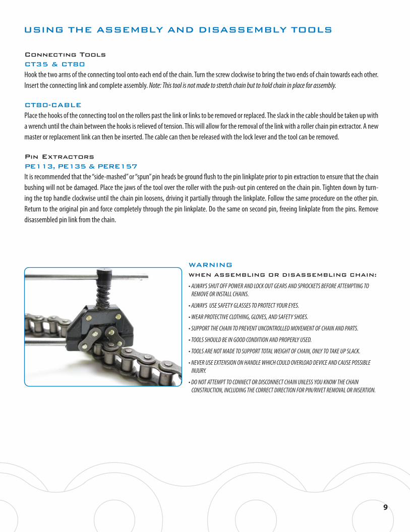
Hook the two arms of the connecting tool onto each end of the chain. Turn the screw clockwise to bring the two ends of chain towards each other. Insert the connecting link and complete assembly. Note: This tool is not made to stretch chain but to hold chain in place for assembly.
CT80-CABLE
Place the hooks of the connecting tool on the rollers past the link or links to be removed or replaced. The slack in the cable should be taken up with a wrench until the chain between the hooks is relieved of tension. This will allow for the removal of the link with a roller chain pin extractor. A new master or replacement link can then be inserted. The cable can then be released with the lock lever and the tool can be removed.
Pin ExtractorsPE113, PE135 & PERE157
It is recommended that the “side-mashed” or “spun” pin heads be ground flush to the pin linkplate prior to pin extraction to ensure that the chain bushing will not be damaged. Place the jaws of the tool over the roller with the push-out pin centered on the chain pin. Tighten down by turn-ing the top handle clockwise until the chain pin loosens, driving it partially through the linkplate. Follow the same procedure on the other pin. Return to the original pin and force completely through the pin linkplate. Do the same on second pin, freeing linkplate from the pins. Remove disassembled pin link from the chain.
USING THE ASSEMBLY AND DISASSEMBLY TOOLS
WARNING WHEN ASSEMBLING OR DISASSEMBLING CHAIN:
• ALWAYS SHUT OFF POWER AND LOCK OUT GEARS AND SPROCKETS BEFORE ATTEMPTING TO REMOVE OR INSTALL CHAINS.
• ALWAYS USE SAFETY GLASSES TO PROTECT YOUR EYES.
• WEAR PROTECTIVE CLOTHING, GLOVES, AND SAFETY SHOES.
• SUPPORT THE CHAIN TO PREVENT UNCONTROLLED MOVEMENT OF CHAIN AND PARTS.
• TOOLS SHOULD BE IN GOOD CONDITION AND PROPERLY USED.
• TOOLS ARE NOT MADE TO SUPPORT TOTAL WEIGHT OF CHAIN, ONLY TO TAKE UP SLACK.
• NEVER USE EXTENSION ON HANDLE WHICH COULD OVERLOAD DEVICE AND CAUSE POSSIBLE INJURY.
• DO NOT ATTEMPT TO CONNECT OR DISCONNECT CHAIN UNLESS YOU KNOW THE CHAIN CONSTRUCTION, INCLUDING THE CORRECT DIRECTION FOR PIN/RIVET REMOVAL OR INSERTION.

ASME/ANSI SERIES CHAINSingle and Multi-StrandThese chains are built to ASME /ANSI B29.1 standards for dimensions, interoperability, and sprocket fit and exceed the established standards for
tensile strength.
Note: ASME/ANSI 60 and larger chains are available as cottered or riveted type design. Chart continues on next page.Multi-strand chains are available with slip-fit (standard) or press-fit center plates.*Chains are rollerless – dimension shown is bushing diameter. ** Maximum values are shown.
Dimensions in Inches
Diamond series chains have been made in Indianapolis, Indiana since 1890.Did You Know?
10
ASME/ANSINumber
PitchInches
Roller Width
RollerDiameter
PinDiameter
eLink PlatThickness C R K
Pounds PerFoot
AverageTensile Strength
25
25-2
25-3
35
35-2
35-3
35-4
35-5
35-6
40
40-2
40-3
40-4
40-6
41
50
50-2
50-3
50-4
50-5
50-6
50-8
50-10
60
60-2
60-3
60-4
60-5
60-6
60-8
60-10
80
80-2
1/4
1/4
1/4
3/8
3/8
3/8
3/8
3/8
3/8
1/2
1/2
1/2
1/2
1/2
1/2
5/8
5/8
5/8
5/8
5/8
5/8
5/8
5/8
3/4
3/4
3/4
3/4
3/4
3/4
3/4
3/4
1
1
1/8
1/8
1/8
3/16
3/16
3/16
3/16
3/16
3/16
5/16
5/16
5/16
5/16
5/16
1/4
3/8
3/8
3/8
3/8
3/8
3/8
3/8
3/8
1/2
1/2
1/2
1/2
1/2
1/2
1/2
1/2
5/8
5/8
*.130
*.130
*.130
*.200
*.200
*.200
*.200
*.200
*.200
.312
.312
.312
.312
.312
.306
.400
.400
.400
.400
.400
.400
.400
.400
.469
.469
.469
.469
.469
.469
.469
.469
.625
.625
.090
.090
.090
.141
.141
.141
.141
.141
.141
.156
.156
.156
.156
.156
.141
.200
.200
.200
.200
.200
.200
.200
.200
.234
.234
.234
.234
.234
.234
.234
.234
.312
.312
.030
.030
.030
.050
.050
.050
.050
.050
.050
.060
.060
.060
.060
.060
.050
.080
.080
.080
.080
.080
.080
.080
.080
.094
.094
.094
.094
.094
.094
.094
.094
.125
.125
….
0.252
0.252
….
0.399
0.399
0.399
0.399
0.399
….
0.566
0.566
0.566
0.566
….
….
0.713
0.713
0.713
0.713
0.713
0.713
0.713
….
0.897
0.897
0.897
0.897
0.897
0.897
0.897
….
1.153
0.08
0.16
0.25
0.21
0.45
0.68
0.91
1.14
1.37
0.41
0.80
1.20
1.60
2.42
0.26
0.70
1.40
2.09
2.78
3.47
4.17
5.56
6.93
0.99
1.95
2.88
3.90
4.97
5.96
7.94
9.92
1.73
3.37
875
1750
2625
2100
4200
6300
8400
10500
12600
4000
8000
12000
16000
24000
2400
6600
13200
19800
26400
33000
39600
52800
66000
8500
17000
25500
34000
42500
51000
68000
85000
14500
29000
0.205
0.205
0.205
0.308
0.308
0.308
0.308
0.308
0.308
0.410
0.410
0.410
0.410
0.410
0.310
0.512
0.512
0.512
0.512
0.512
0.512
0.512
0.512
0.615
0.615
0.615
0.615
0.615
0.615
0.615
0.615
0.820
0.820
0.238
0.238
0.238
0.356
0.356
0.356
0.356
0.356
0.356
0.475
0.475
0.475
0.475
0.475
0.383
0.594
0.594
0.594
0.594
0.594
0.594
0.594
0.594
0.713
0.713
0.713
0.713
0.713
0.713
0.713
0.713
0.950
0.950
E** H**

ASME/ANSI SERIES CHAIN
Dimensions in Inches
RROLLERWIDTH
ROLLER DIAMETER PI TCH
C
R CK
H EDIAMOND D AMOND
** Maximum values are shown.
11
ASME/ANSINumber
PitchInches
Roller Width
RollerDiameter
PinDiameter
eLink PlatThickness K
Pounds PerFoot
AverageTensile Strength
E**
5/8
5/8
5/8
5/8
5/8
3/4
3/4
3/4
3/4
3/4
3/4
3/4
1
1
1
1
1
1
1
1
1
1
1
1
1
1 1/4
1 1/4
1 1/4
1 1/4
1 1/4
1 13/32
1 13/32
1 13/32
1 1/2
1 1/2
1 1/2
1 1/2
1 1/2
1 7/8
1 7/8
1 7/8
.625
.625
.625
.625
.625
.750
.750
.750
.750
.750
.750
.750
.875
.875
.875
.875
.875
.875
.875
.875
1.000
1.000
1.000
1.000
1.000
1.125
1.125
1.125
1.125
1.125
1.406
1.406
1.406
1.562
1.562
1.562
1.562
1.562
1.875
1.875
1.875
.312
.312
.312
.312
.312
.375
.375
.375
.375
.375
.375
.375
.437
.437
.437
.437
.437
.437
.437
.437
.500
.500
.500
.500
.500
.562
.562
.562
.562
.562
.687
.687
.687
.781
.781
.781
.781
.781
.937
.937
.937
.125
.125
.125
.125
.125
.156
.156
.156
.156
.156
.156
.156
.187
.187
.187
.187
.187
.187
.187
.187
.219
.219
.219
.219
.219
.250
.250
.250
.250
.250
.281
.281
.281
.312
.312
.312
.312
.312
.375
.375
.375
80-3
80-4
80-5
80-6
80-8
100
100-2
100-3
100-4
100-5
100-6
100-8
120
120-2
120-3
120-4
120-5
120-6
120-8
120-10
140
140-2
140-3
140-4
140-6
160
160-2
160-3
160-4
160-6
180
180-2
180-3
200
200-2
200-3
200-4
200-6
240
240-2
240-3
1
1
1
1
1
1 1/4
1 1/4
1 1/4
1 1/4
1 1/4
1 1/4
1 1/4
1 1/2
1 1/2
1 1/2
1 1/2
1 1/2
1 1/2
1 1/2
1 1/2
1 3/4
1 3/4
1 3/4
1 3/4
1 3/4
2
2
2
2
2
2 1/4
2 1/4
2 1/4
2 1/2
2 1/2
2 1/2
2 1/2
2 1/2
3
3
3
H**
3.74
4.90
6.06
7.22
9.53
1.73
3.14
4.56
5.97
7.38
8.78
11.60
2.14
3.93
5.72
7.52
9.31
11.10
14.68
18.26
2.31
4.24
6.16
8.09
11.94
2.73
5.04
7.35
9.66
14.27
3.15
5.75
8.34
3.44
6.26
9.08
11.90
17.52
4.32
7.77
11.23
3.62
4.79
5.94
7.10
9.40
1.61
3.02
4.43
5.84
7.25
8.66
11.48
2.00
3.79
5.58
7.38
9.17
10.96
14.54
18.12
2.14
4.07
6.00
7.93
11.78
2.54
4.85
7.16
9.47
14.09
2.88
5.48
8.07
3.12
5.94
8.76
11.58
17.21
3.83
7.27
10.73
1.153
1.153
1.153
1.153
1.153
….
1.408
1.408
1.408
1.408
1.408
1.408
….
1.408
1.408
1.408
1.408
1.408
1.408
1.408
….
1.924
1.924
1.924
1.924
….
2.305
2.305
2.305
2.305
….
2.592
2.592
….
2.817
2.817
2.817
2.817
….
3.458
3.458
5.02
6.73
8.40
10.07
13.41
2.51
4.91
7.40
9.80
12.20
14.60
19.40
3.69
7.35
11.10
14.70
18.43
22.11
29.47
36.83
5.00
9.65
14.30
18.95
28.25
6.53
12.83
19.03
25.60
37.78
9.06
17.67
26.20
10.65
21.50
32.30
42.90
64.50
17.03
33.44
49.77
43500
58000
72500
87000
116000
24000
48000
72000
96000
120000
144000
192000
34000
68000
102000
136000
170000
204000
272000
340000
46000
92000
138000
184000
276000
58000
116000
174000
232000
348000
76000
152000
228000
95000
190000
285000
380000
570000
157600
315200
472800
0.820
0.820
0.820
0.820
0.820
1.025
1.025
1.025
1.025
1.025
1.025
1.025
1.230
1.230
1.230
1.230
1.230
1.230
1.230
1.230
1.435
1.435
1.435
1.435
1.435
1.640
1.640
1.640
1.640
1.640
1.845
1.845
1.845
2.050
2.050
2.050
2.050
2.050
2.422
2.422
2.422
0.950
0.950
0.950
0.950
0.950
1.188
1.188
1.188
1.188
1.188
1.188
1.188
1.425
1.425
1.425
1.425
1.425
1.425
1.425
1.425
1.663
1.663
1.663
1.663
1.663
1.900
1.900
1.900
1.900
1.900
2.138
2.138
2.138
2.375
2.375
2.375
2.375
2.375
2.806
2.806
2.806
R

HEAVY SERIES CHAIN
Single and Multi-StrandDiamond heavy series chains are built to ASME/ANSI B29.1 standards and feature linkplates that are 1/32” thicker than standard series linkplates. Heavy series chains are intended for applications subjected to heavy shock loads, abrupt starts and stops, and forward and reverse travel.
Dimensions in Inches
Note: ASME/ANSI 60 and larger chains are available as cottered or riveted type design. Multi-strand chains are available with slip-fit (standard) or press-fit center plates.* Maximum values are shown.
12
ASME/ANSINumber
PitchInches
Roller Width
RollerDiameter
PinDiameter
eLink PlatThickness K
Pounds PerFoot
AverageTensile Strength
E* H*
60H
60H-2
60H-3
60H-4
80H
80H-2
80H-3
80H-4
100H
100H-2
100H-3
100H-4
120H
120H-2
120H-3
120H-4
120H-6
140H
140H-2
140H-3
140H-4
160H
160H-2
160H-3
160H-4
180H
180H-2
180H-3
200H
200H-2
200H-3
240H
3/4
3/4
3/4
3/4
1
1
1
1
1 1/4
1 1/4
1 1/4
1 1/4
1 1/2
1 1/2
1 1/2
1 1/2
1 1/2
1 3/4
1 3/4
1 3/4
1 3/4
2
2
2
2
2 1/4
2 1/4
2 1/4
2 1/2
2 1/2
2 1/2
3
1/2
1/2
1/2
1/2
5/8
5/8
5/8
5/8
3/4
3/4
3/4
3/4
1
1
1
1
1
1
1
1
1
1 1/4
1 1/4
1 1/4
1 1/4
1 13/32
1 13/32
1 13/32
1 1/2
1 1/2
1 1/2
1 7/8
.469
.469
.469
.469
.625
.625
.625
.625
.750
.750
.750
.750
.875
.875
.875
.875
.875
1.000
1.000
1.000
1.000
1.125
1.125
1.125
1.125
1.406
1.406
1.406
1.562
1.562
1.562
1.875
.234
.234
.234
.234
.312
.312
.312
.312
.375
.375
.375
.375
.437
.437
.437
.437
.437
.500
.500
.500
.500
.562
.562
.562
.562
.687
.687
.687
.781
.781
.781
.937
.125
.125
.125
.125
.156
.156
.156
.156
.187
.187
.187
.187
.219
.219
.219
.219
.219
.250
.250
.250
.250
.281
.281
.281
.281
.312
.312
.312
.375
.375
.375
.500
1.24
2.27
3.31
4.34
1.57
2.84
4.14
5.42
1.86
3.41
4.95
6.49
2.27
4.20
6.13
8.06
11.91
2.44
4.50
6.56
8.62
2.86
5.30
7.75
10.17
3.28
6.00
8.73
3.71
6.79
9.88
4.85
1.17
2.20
3.24
4.26
1.45
2.72
4.02
5.30
1.74
3.28
4.82
6.30
2.13
4.60
5.99
7.92
11.77
2.28
4.34
6.39
8.45
2.68
5.12
7.56
10.00
3.01
5.73
8.46
3.39
6.48
9.56
4.35
….
1.028
1.028
1.028
….
1.283
1.283
1.283
….
1.54
1.54
1.54
….
1.924
1.924
1.924
1.924
….
2.055
2.055
2.055
….
2.436
2.436
2.436
….
2.723
2.723
….
3.083
3.083
….
1.18
2.33
3.47
4.61
2.02
3.93
5.92
7.87
2.82
5.58
8.32
11.04
4.08
8.04
11.99
15.94
23.84
5.40
10.65
15.90
21.10
7.03
13.88
20.68
27.62
9.59
18.86
28.14
13.38
26.38
40.85
21.08
8500
17000
25500
34000
14500
29000
43500
58000
24000
48000
72000
96000
34000
68000
102000
136000
204000
46000
92000
138000
184000
58000
116000
174000
232000
76000
152000
228000
110000
220000
330000
157600
.615
.615
.615
.615
.820
.820
.820
.820
1.025
1.025
1.025
1.025
1.230
1.230
1.230
1.230
1.230
1.435
1.435
1.435
1.435
1.640
1.640
1.640
1.640
1.845
1.845
1.845
2.050
2.050
2.050
2.422
.713
.713
.713
.713
.950
.950
.950
.950
1.188
1.188
1.188
1.188
1.425
1.425
1.425
1.425
1.425
1.663
1.663
1.663
1.663
1.900
1.900
1.900
1.900
2.138
2.138
2.138
2.375
2.375
2.375
2.806

Dimensions in Inches
HIGH STRENGTH SERIES CHAINDiamond high strength chains are built to ASME/ANSI B29.1 standards and are intended for applications subjected to heavy loads or lifting.
In addition to the high strength series, Diamond Chain also manufactures hoist chain and rollerless lift chain for heavy loads or lifting applications.
High Strength and High Strength Oval Contour Drive Chains
Diamond high strength (HS) and high strength oval contour (HSOC) chains are built to ASME/ANSI B29.1 standards. These chains feature through-hardened, medium carbon alloy steel pins for higher working load capacity and additional resistance versus standard heavy series drive chains in heavy load and pulsating applications. High strength oval contour drive chains feature medium carbon alloy steel pins and full oval contour pin linkplates and roller linkplates for maximum plate rigidity in high load applications.
Offset links and slip-fit connecting links are not recommended for high strength or lift chain applications.
* Maximum values are shown.
High Strength
High Strength Oval Contour
RROLLERWIDTH
ROLLER DIAMETER PITCH
C
R CK
H ED AMONDD IAMOND
13
ASME/ANSI Number
PitchInches
Roller Width
RollerDiameter
PinDiameter
Link PlateThickness
Pounds PerFoot
AverageTensile Strengt h
60HS
60HSOC
80HS
80HSOC
100HS
100HSOC
120HS
140HS
160HS
180HS
200HS
200HS-2
200HS-3
240HS
3/4
3/4
1
1
1 1/4
1 1/4
1 1/2
1 3/4
2
2 1/4
2 1/2
2 1/2
2 1/2
3
1/2
1/2
5/8
5/8
3/4
3/4
1
1
1 1/4
1 13/32
1 1/2
1 1/2
1 1/2
1 7/8
.469
.469
.625
.625
.750
.750
.875
1.000
1.125
1.406
1.562
1.562
1.562
1.875
.234
.234
.312
.312
.375
.375
.437
.500
.562
.687
.781
.781
.781
.937
.125
.125
.156
.156
.187
.187
.219
.250
.281
.312
.375
.375
.375
.500
1.24
1.24
1.57
1.57
1.86
1.86
2.27
2.44
2.86
3.28
3.71
6.79
9.88
4.85
1.17
1.17
1.45
1.45
1.74
1.74
2.13
2.28
2.68
3.01
3.39
6.48
9.56
4.35
1.18
1.42
2.02
2.38
2.82
3.29
4.08
5.40
7.03
9.59
13.75
26.38
40.85
21.08
12000
12000
21000
21000
30000
30000
41000
56000
70000
95000
136000
270000
405000
157600
….
….
….
….
….
….
….
….
….
….
….
3.083
3.083
E* H* .615
.713
.820
.950
1.025
1.188
1.230
1.435
1.640
1.845
2.050
2.050
2.050
2.422
.713
.713
.950
.950
1.188
1.188
1.425
1.663
1.900
2.138
2.375
2.375
2.375
2.806….
ROLLERWIDTH
ROLLER DIAMETER PITCH
R C
H

DOUBLE-PITCH ROLLER CHAIN
Double-Pitch Power Transmission Roller ChainDiamond Chain double-pitch power transmission chains are built to ASME/ANSI B29.3 standards, have figure-eight style linkplates, and a pitch twice that of the standard series chains. Typical uses for these chains include light load drives commonly found in agricultural applications.
Double-Pitch Conveyor Roller ChainDiamond Chain double-pitch conveyor chains are built to ASME/ANSI B29.4 standards, have oval contour linkplates, and can be produced with either standard or oversized rollers. These chains are used in conveyor applications where loads are low and speeds are moderate and can be produced with a variety of attachments.
Dimensions in Inches
Standard Rollers
Oversized RollersDimensions in Inches
* Nominal values are shown.
* Nominal values are shown.
* Nominal values are shown.
Dimensions in Inches
Oversized Rollers
14
ASME/ANSI Number
PitchInches
Roller Width
RollerDiameter
PinDiameter
Link PlateThickness
Pounds PerFoot
AverageTensile Strengt h H*
2040
2050
2060
2080
1
1 1/4
1 1/2
2
5/16
3/8
1/2
5/8
0.312
0.400
0.469
0.625
0.156
0.200
0.234
0.312
0.060
0.080
0.094
0.125
0.76
0.92
1.11
1.44
0.68
0.84
1.05
1.32
0.28
0.52
0.72
1.13
3700
6100
8500
14500
0.475
0.594
0.712
0.950
ASME/ANSI Number
PitchInches
Roller Width
RollerDiameter
PinDiameter
Link PlateThickness
Pounds PerFoot
AverageTensile Strengt h H*
C2040
C2050
C2060H
C2080H
C2100H
C2120H
C2160H
1
1 1/4
1 1/2
2
2 1/2
3
4
1/3
3/8
1/2
5/8
3/4
1
1 1/14
0.312
0.400
0.469
0.625
0.750
0.875
1.125
0.156
0.200
0.234
0.312
0.375
0.437
0.562
0.060
0.080
0.125
0.156
0.187
0.219
0.281
0.76
0.92
1.25
1.57
1.86
2.27
2.86
0.68
0.84
1.18
1.45
1.74
2.13
2.68
0.34
0.58
1.05
1.4
2.48
3.60
6.18
3125
4880
7030
12500
24000
34000
58000
0.475
0.594
0.712
0.95
1.187
1.425
1.9
ASME/ANSI Number
PitchInches
Roller Width
RollerDiameter
PinDiameter
Link PlateThickness
Pounds PerFoot
AverageTensile Strengt h H*
C2042
C2052
C2062H
C2082H
C2102H
C2122H
C2162H
1
1 1/4
1 1/2
2
2 1/2
3
4
1/3
3/8
1/2
5/8
3/4
1
1 1/4
0.625
0.750
0.875
1.125
1.562
1.750
2.250
0.156
0.200
0.234
0.312
0.375
0.437
0.562
0.060
0.080
0.125
0.156
0.187
0.219
0.281
0.76
0.92
1.25
1.57
1.86
2.27
2.86
0.68
0.84
1.18
1.45
1.74
2.13
2.68
0.5
0.81
1.42
2.13
3.51
5.48
9.34
3125
4880
7030
14500
24000
34000
58000
0.475
0.594
0.712
0.95
1.187
1.425
1.9
H
R C

MAINTENANCE FREE CHAINDiamond maintenance free chains are intended for applications where regular lubrication is not possible or practical.
DURALUBE® ChainThe DURALUBE series features a one-piece powdered metal bushing and roller combination lubricated under vacuum to provide supplemental lubrication between regularly scheduled inspection and maintenance.
Dimensions in Inches
RING LEADER® O-ring Drive ChainThe RING LEADER o-ring series is designed for applications where regular lubrication is not possible. These chains are constructed with gaskets that seal in Diamond Chain proprietary lubricant and keep contaminants out.
*Maximum values are shown.
RING LEADER o-ring chain can routinely operate in ambient temperatures up to 150oF. For higher temperatures, special o-rings can be substituted, allowing operation in temperatures of 400oF or greater.
Did You Know?15
PitchInches
Roller Width
RollerDiameter
PinDiameter
Link PlateThickness
Pounds PerFoot
AverageTensile Strength
ASME/ANSI Number50 XLO
50H XLO
60 XLO
80 XLO
100 XLO
120 XLO
140 XLO
160 XLO
C2050 XLO
C2060H XLO
5/8
5/8
3/4
1
1 1/4
1 1/2
1 3/4
2
1 1/4
1 1/2
3/8
3/8
1/2
5/8
3/4
1
1
1 1/4
3/8
1/2
.400
.400
.469
.625
.750
.875
1.000
1.125
.400
.469
.200
.214
.234
.312
.375
.437
.500
.562
.200
.234
.080
.094
.094
.125
.156
.187
.219
.250
.080
.125
0.95
1.02
1.21
1.51
1.83
2.24
2.49
2.96
0.95
1.27
0.89
0.96
1.13
1.41
1.74
2.12
2.35
2.82
0.89
1.21
0.72
0.93
1.01
1.77
2.55
3.76
5.10
6.66
0.59
1.17
6500
9300
7700
13500
22000
30000
42000
52000
6500
7700
E* H*
.512
.512
.615
.820
1.025
1.230
1.435
1.640
.594
.594
.713
.950
1.188
1.425
1.663
1.800
.594
.712
….
….
Dimensions in Inches
Due to the nature of DURALUBE drive chain construction, note maximum speed limitations.
PitchInches
Roller Width
RollerDiameter
PinDiameter
Link PlateThickness K
Pounds PerFoot
AverageTensile Strength
MaximumChain Speed
ASME/ANSI Number40-DL40-2-DL50-DL50-2-DL60-DL60-2-DL80-DL2040-DL2050-DL2060-DL
1/21/25/85/83/43/41 1 1 1/41 1/2
5/165/163/83/81/21/25/85/163/81/2
.312
.312
.400
.400
.469
.469
.625
.312
.400
.469
.156
.156
.200
.200
.234
.234
.312
.156
.200
.234
.060
.060
.080
.080
.094
.094
.125
.060
.080
.094
0.72 0.671.29 1.240.89 0.831.60 1.551.11 1.042.01 1.941.44 1.320.76 0.680.92 0.841.11 1.05
…. 0.400.566 0.81
…. 0.65
0.713 1.27
…. 0.95
0.897 1.85
…. 1.60
…. 0.30
…. 0.47
…. 0.70
330066005200
104007400
1480013000
330052007400
1300 ft/min1300 ft/min1000 ft/min1000 ft/min
850 ft/min850 ft/min650 ft/min 600 ft/min600 ft/min600 ft/min
E* H*.410
.410
.512
.512
.615
.615
.820
.....
.....
.....
.475
.475
.594
.594
.713
.713
.950
.475
.594
.712
* Maximum values are shown.
Note:Ambient temperature should not exceed 120 o Fahrenheit.
ROLLERWIDTH
ROLLER DIAMETER PITCH
R C ROLLERWIDTH
ROLLER DIAMETER
R
PITCH
C
H EH
ROLLER WIDTH
ROLLER DIAMETER PITCH
R CROLLER WIDTH
ROLLER DIAMETER
R
P TCH
CK
ROLLER WIDTHR
ROLLER DIAMETER P TCH
C
HH H
EE

Dimensions in Inches
Dust Stopper™ Drive ChainThe Dust Stopper series combines the maintenance-free benefits of the DURALUBE series with the advanced protection from contaminants of Diamond’s RING LEADER o-ring series.
Note: Due to the nature of DURALUBE drive chain construction, note maximum speed limitations. Ambient temperature should not exceed 120 o Fahrenheit.
COUPLING CHAINDiamond coupling chains are designed to work in concert with drive couplings to provide near-seamless power transmission.
Dimensions in Inches
16
LENGTH IN PITCHES
ROLLER DIAMETER PITCH
ASME/ANSI Number
PitchInches
Roller Width
RollerDiameter
Pounds PerFoot
D4012
D4016
D5016
D5018
D6018
D6020
D6022
D8018
D8020
D10018
D10020
D12018
D12022
0.5
0.5
5/8
5/8
3/4
3/4
3/4
1
1
1 1/4
1 1/4
1 1/2
1 1/2
0.312
0.312
0.375
0.375
0.500
0.500
0.500
0.625
0.625
0.750
0.750
1.000
1.000
0.312
0.312
0.400
0.400
0.469
0.469
0.469
0.625
0.625
0.750
75.000
0.875
0.875
1.297
1.297
1.592
1.592
1.980
1.980
1.980
2.567
2.567
3.162
3.162
3.977
3.977
1.24
1.24
1.55
1.55
1.94
1.94
1.94
2.47
2.47
3.02
3.02
3.79
3.79
0.566
0.566
0.713
0.713
0.897
0.897
0.897
1.153
1.153
1.408
1.408
1.789
1.789
12
16
16
18
18
20
22
18
20
18
20
18
22
LengthPitches
0.41
0.55
1.12
1.26
2.16
2.40
2.64
5.00
5.56
9.24
10.30
16.20
19.80
K
PitchInches
Roller Width
RollerDiameter
Pi nDiameter
Link PlateThickness
Pounds PerFoot
AverageTensile Strength
Max. Speedft/min
ASME/ANSI Number
40 XDLO
50 XDLO
60 XDLO
80 XDLO
1/2
5/8
3/4
1
5/16
3/8
1/2
5/8
.312
.400
.469
.625
.156
.200
.234
.312
.060
.080
.094
.125
0.78
0.95
1.21
1.51
0.73
0.59
1.13
1.41
0.43
0.68
0.95
1.59
3300
5200
7400
13000
1300 ft/min
1000 ft/min
850 ft/min
650 ft/min
E* H*
0.410
0.512
0.615
0.820
0.475
0.594
0.713
0.950
ROLLER WIDTH
ROLLER DIAMETER PITCH
R C
H E

ADDITIONAL PRODUCTSIn addition to the items featured in this catalog, the Diamond Chain Company also manufactures these chains:
Agriculture Roller ChainA full assortment of agricultural attachments for use with Diamond standard ASME/ANSI roller chain.
Attachment Roller ChainSingle and double-pitch roller chains can be assembled with attachments or extended pins.
British Standard Roller ChainA full assortment of 05B simplex through 48B triplex British Standard chains manufactured to the International Standards Organization dimensions (ISO 606, BS 228, DIN 8187) for dimensions, interoperability, and sprocket fit.
Corrosion/Moisture Resistant Roller ChainA full line of corrosion/moisture resistant chains for use in environments where chains are exposed to humidity or corrosive agents. These chains are available in stainless steel, nickel plated, or with Diamond Chain’s proprietary anti-corrosive exterior (ACE®) which features a two stage zinc-nickel and non-hexavalent chromium coating. Standard attachments are also available.
Flexible ChainPOWER CURVE Chain
Manufactured using a pin that is both smaller in diameter and slightly longer than its standard series equivalent. The design allows for extra clearance between the pin and the bushing and lateral deviations in overall chain width.
TUF-FLEX Chain Designed to handle shaft or sprocket misalignment more than lateral turns, up to four inches of lateral displacement in every four feet of chain length, and up to eight degrees of axial twist. Ideal for heavy-duty construction machinery applications.
High Strength/Lift ChainHoist Chain
Dimensionally identical to standard series chains but also incorporate pins produced from medium carbon alloy steel, through-hardened to give chains higher working load capacity and additional resistance to fatigue.
Rollerless Lift Chain
Designed for tension linkages where frequent articulation requires the increased bearing area of roller chain. Rollerless lift chains are dimension-ally identical to standard series chains but are produced without rollers.
Infinity Series ChainIncludes ANSI 25 through 160 and ISO 05B through 048B, single and multi-strand roller chain in carbon and stainless steel. Non-Standard ChainDesigned prior to adoption of ASME/ANSI standards and available as special order products.
17

TROUBLESHOOTING GUIDE
19
C
Tu
ONDITION/SYMPTOM POSSIBLE CAUSE WHAT TO DOTight Joints Dirt or foreign material in chain joints. Clean and re-lubricate chain.
Inadequate lubrication. Replace chain. Re-establish proper lubrication.
Misalignment. Replace sprockets and chain if needed. Realign sprockets.
Internal corrosion or rust. Replace chain. Eliminate cause of corrosion or protect chain.
Overload bends pins or spreads roller linkplates. Replace chain. Eliminate cause of overload.
Rusted Chain Exposed to moisture. Replace chain. Protect from moisture.
Water in lubricant. Change lubricant. Protect lubrication system from water. Replace chain.
Inadequate lubrication. Provide or re-establish proper lubrication. Replace chain if needed.
rned Pins Overload. Replace chain. Eliminate cause of overload.
Inadequate lubrication. Replace chain. Re-establish proper lubrication.
Enlarged Holes Overload. Replace chain. Eliminate cause of overload.
Broken PinsBroken Linkplates
Extreme Overload. Replace chain. Replace sprockets if indicated. Eliminate cause of overload or redesign drive for larger pitch chain.
Broken, Cracked, or Deformed Rollers Speed too high. Replace chain. Reduce speed.
Sprockets too small. Replace chain. Use larger sprockets, or possibly redesign drive for smaller pitch chain.
Chain riding too high on sprocket teeth. Replace chain. Re-tension chain more often.
Pin Galling Speed or load too high. Reduce speed or load. Possibly redesign drive for smaller pitch chain.
Inadequate lubrication. Provide or re-establish proper lubrication.
Chain Climbs Sprocket Teeth Excess chain slack. Re-tension chain.
Excessive chain wear. Replace and re-tension chain.
Excessive sprocket wear. Replace sprockets and chain.
Excessive overload. Replace chain. Eliminate cause of overload.
TROUBLESHOOTING GUIDE
5% of H
H
20
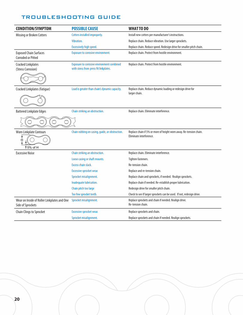
CONDITION/SYMPTOM POSSIBLE CAUSE WHAT TO DOMissing or Broken Cotters Cotters installed improperly. Install new cotters per manufacturer’s instructions.
Vibration. Replace chain. Reduce vibration. Use larger sprockets.
Excessively high speed. Replace chain. Reduce speed. Redesign drive for smaller pitch chain.
Exposed Chain Surfaces Corroded or Pitted
Exposure to corrosive environment. Replace chain. Protect from hostile environment.
Cracked Linkplates (Stress Corrosion)
Exposure to corrosive environment combined Replace chain. Protect from hostile environment.
Cracked Linkplates (Fatigue) Load is greater than chain’s dynamic capacity. Replace chain. Reduce dynamic loading or redesign drive for larger chain.
Battered Linkplate Edges Chain striking an obstruction. Replace chain. Eliminate interference.
Worn Linkplate Contours Chain rubbing on casing, guide, or obstruction. Replace chain if 5% or more of height worn away. Re-tension chain. Eliminate interference.
Excessive Noise Chain striking an obstruction. Replace chain. Eliminate interference.
Loose casing or shaft mounts. Tighten fasteners.
Excess chain slack. Re-tension chain.
Excessive sprocket wear. Replace and re-tension chain.
Sprocket misalignment. Replace chain and sprockets, if needed. Realign sprockets.
Inadequate lubrication. Replace chain if needed. Re-establish proper lubrication.
Chain pitch too large Redesign drive for smaller pitch chain.
Too few sprocket teeth. Check to see if larger sprockets can be used. If not, redesign drive.
Wear on Inside of Roller Linkplates and One Side of Sprockets
Sprocket misalignment. Replace sprockets and chain if needed. Realign drive. Re-tension chain.
Chain Clings to Sprocket Excessive sprocket wear. Replace sprockets and chain.
Sprocket misalignment. Replace sprockets and chain if needed. Realign sprockets.

ROLLER CHAIN WEAR
Chain does not “stretch” – elongation is caused when material is removed from the pins and bushings.
The individual joints in a roller chain articulate as they enter and exit the sprockets. This articulation results in wear on the pins and bushings. As material is worn away from these surfaces, the chain will gradually elon-gate.
Elongation ControlElongation is normal and may be minimized through proper lubrication and drive maintenance. The rate of wear is dependent upon the load and the amount of bearing area between pin and bushing, the material and surface condition of the bearing surfaces, the adequacy of lubri-cation, and the frequency and degree of articulation between pins and bushings. The latter is determined by the quantity of sprockets in the drive, their speeds, the number of teeth, and the length of the chain in pitches.
Check Chain WearRoller chains should be replaced when worn (elongated beyond 3%) or when the chain rollers begin to “ride high” near the tips of the teeth on relatively large sprockets. Do not connect or splice a new section to a worn chain. Do not continue to run a chain worn in excess of 3% (or less in some applications), the chain will not engage the sprockets properly and increased damage to the sprockets may occur.
For additional chain wear gauges, please contact The Diamond Chain Company at [email protected].
21

HOW TO MEASURE CHAIN WEAR
1) As a safety precaution, shut off power and lock out gears and sprockets before attempting to measure chain wear.
2) Determine the pitch of the chain. This is typically stamped on the outer linkplates of the chain. It can also be determined by measuring the distance from the center of one pin to the center of the next pin. Refer to the Diamond Chain product catalog for a list of ANSI standard chain models and correlating pitch measurements or visit www.diamondchain.com.
3) For reliable linear measurement, a taut span of chain must be used. Using slack chain will result in inaccurate measurements.
4) Choose either a 1.5% or 3% wear elongation limit to check your span of chain. Each percentage correlates to a different side of the scale. The maximum allowable wear elongation is typically 3% for most industrial applications, depending upon sprocket design. In drives having fixed center distances, chains running in parallel, or where smoother operation is required, chain wear should be limited to approximately 1.5%.Example: Using ASME/ANSI 60 roller chain, 13 pitches would measure 9.75 inches for nominal length (13 pitches x .75 pitch). A maximum wear calculation of 3% would be 1.03 x 9.75 or 10.0425 inches. A maximum wear calculation of 1.5% would be 1.015 x 9.75 or 9.896 inches.
5) Refer to the table on the wear gauge for the number of pitches to inspect. The more pitches (pins) included in the measurement provides the truer representation of the average amount of wear distributed throughout the chain. Example: For ASME/ANSI 60 roller chain, 13 pitches will be measured.
6) Place the inside corner of the wear scale around one pin, using that pin as “0,” or your starting point.
7) Starting at “0,” count the number of pins/pitches to be measured for your chain’s length. Example: Count from 0 to 13 for ASME/ANSI 60 roller chain.
8) If the center of the indicated pin does not reach the wear line for the correspond-ing chain size, the chain has not reached the wear limit. Example: For ASME/ANSI 60 roller chain, if the center of the 13th pin does not reach the # 60 wear mark, the chain remains usable.
9) If the center of the indicated pin is at or beyond the indicated line, the chain is worn to the wear limit (1.5% or 3%, depending on the scale used) and should be replaced. Example: For ASME/ANSI 60 roller chain, if the center of the 13th pin reaches or exceeds the # 60 wear mark, the chain should be replaced.
0 1 2 3 4 5 6 7 8 9 10 12 13
11 12 13
131211
22
253540506080100
ANSI
06B08B10B12B16B20B
33P23P18P15P13P11P
9P
120140160180200240
24B28B32B
40B
8P6P5P5P5P4P
BS NO. OF PITCHES ANSI BS NO. OF PITCHES

NOTES
23
nothing outlasts a diamond®©The Diamond Chain Company 2013DC-CPG13
DIAMOND® CHAIN COMPANY
AmericasCorporate Headquarters402 Kentucky AvenueIndianapolis, Indiana 46225PH: 1-800 US CHAIN1-800-872-4246Fax: 317-613-2243
Dallas Service Center9120 Premier RowDallas, Texas 75356PH: 1-800-872-4246Fax: 1-214-631-2374
Sacramento Service Center1331 Terminal StreetWest Sacramento, CA 95691PH: 1-800-872-4246Fax: 1-916-372-5801
Canada/MexicoPH: 1-317-638-6431
www.diamondchain.com
United Kingdom Unit 7 – 9Blaydon Industrial ParkChainbridge RoadBlaydon on TyneNE21 5ABPH: +44-191-414-8822
www.diamondchain.co.uk
AsiaXinghong International Building, Room 2009No. 225 Suhong Middle RoadSIP, Suzhou, China 215021PH: +86-512-6265-3075
• • ••
•


![ICLS2009 Seoul Korea Table of contents - Sripatum University · ICLS2009 Seoul Korea Table of contents June 3(Wed), 2009 [ Keynote Speech 1 ] K01 "Emerging Trends of Supply Chain](https://static.fdocuments.in/doc/165x107/5b14a9f57f8b9a3e7c8e1b8d/icls2009-seoul-korea-table-of-contents-sripatum-icls2009-seoul-korea-table.jpg)