
TABLE OF CONTENTS - Premium Supplycdn.premium-supply.com/Eagle_Documentation/HYDRAULIC... 4 Contact...
44
Transcript of TABLE OF CONTENTS - Premium Supplycdn.premium-supply.com/Eagle_Documentation/HYDRAULIC... 4 Contact...

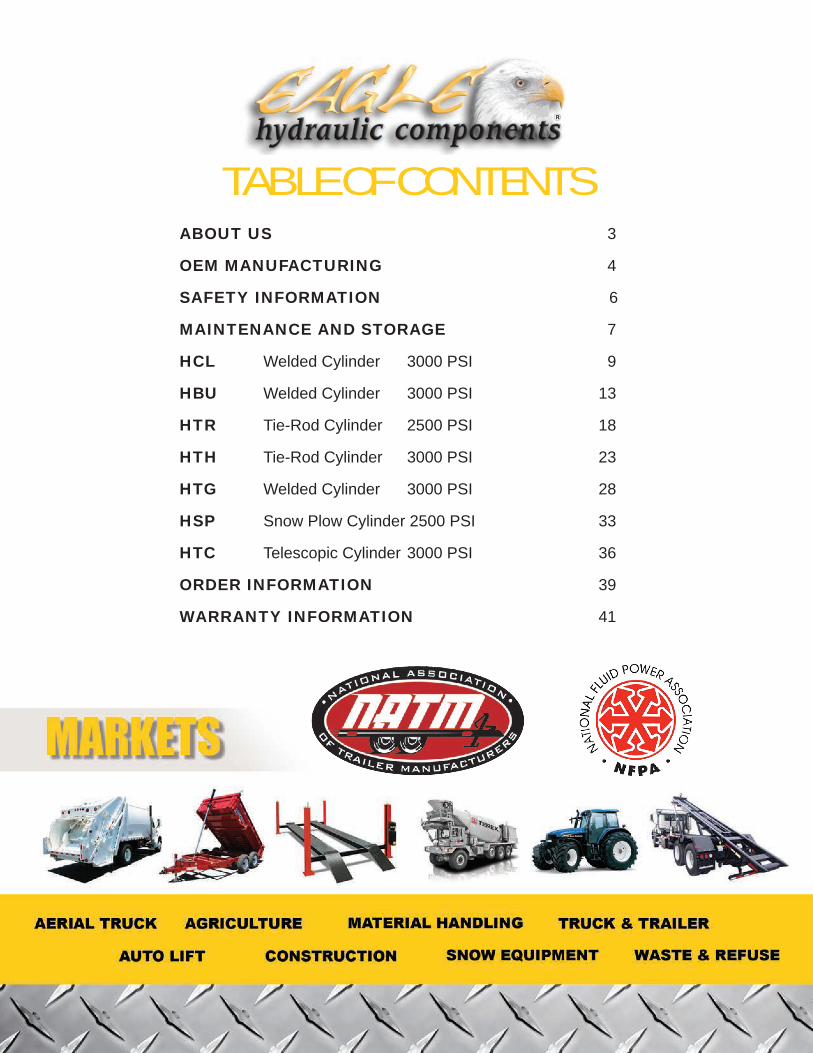
TABLE OF CONTENTSABOUT US 3
OEM MANUFACTURING 4
SAFETY INFORMATION 6
MAINTENANCE AND STORAGE 7
HCL Welded Cylinder 3000 PSI 9
HBU Welded Cylinder 3000 PSI 13
HTR Tie-Rod Cylinder 2500 PSI 18
HTH Tie-Rod Cylinder 3000 PSI 23
HTG Welded Cylinder 3000 PSI 28
HSP Snow Plow Cylinder 2500 PSI 33
HTC Telescopic Cylinder 3000 PSI 36
ORDER INFORMATION 39
WARRANTY INFORMATION 41

3 www.eagle-hydraulic.com
“Highest Quality - Lowest Pricing”
ABOUT USEagle Hydraulic Components Inc. is a Canadian based manufacturer of engineered and standard Hydraulic Cylinders. We also manufacture Eagle branded Hydraulic Power Units in Canada and distribute Hydraulic Motors among many other products.
Serving the mobile equipment industry, our products are designed and supported from our Head Office located in Mirabel Quebec Canada. We have a fully equipped service and repair facility integrated within our 22,000 square foot warehouse located in Montreal, Quebec. We independently own and operate two hydraulic cylinder manufacturing facilities located in the North and South of China. Our manufacturing operations are certified to the ISO TS16949 standard. We are also a certified OEM production supplier to many large North American based corporations.
Our services include on site visits & support, flexible delivery programs, stocking arrangements, inventory updates, flexible warranty and of course service with a smile. With a functional ERP system, we have the capability to match our lead time with your forecast to assure a seamless delivery. We strive to deliver our products to you on time every time.
Be assured that Eagle Hydraulic Components can offer you the best in quality, delivery, service and of course price.
Our motto “Highest Quality - Lowest Pricing”.
The Eagle factory: Tianjin Eagle Hydraulics Cylinders MFG. CO. Lt. is based in Tianjin, China. Our modern 100 000 sq. ft. facility is ISO approved and equipped with industry best equipment.
Our Capabilities
OEM HYDRAULIC CYLINDERSEagle is a Canadian based manufacturer of engineered hydraulic cylinders. Our manufacturing facilities are certified to the ISO TS16949 standard. We are also an approved supplier to many large OEM equipment manufacturers in the mobile industry.
STANDARD HYDRAULIC CYLINDERSEagle offers a complete line of standard hydraulic cylinder products. We manufacture and stock a range of welded body rod cylinders, tie rod cylinders as well as single acting telescopic cylinders.
HYDRAULIC POWER UNITSAs a progressive company, Eagle has developed our own line of hydraulic power units. Designed in Canada utilizing only the best sourced components, our product is high quality, rugged and reliable.
HYDRAULIC COMPONENTSEagle is not only a hydraulic cylinder manufacturer, we add to our portfolio by offering other hydraulic components such as hydraulic motors, gear pumps, vane pumps relief valves and more.
All product specifications are subject to change without prior notice.
4www.eagle-hydraulic.com
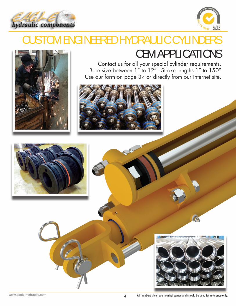
Contact us for all your special cylinder requirements.Bore size between 1” to 12” - Stroke lengths 1” to 150”
Use our form on page 37 or directly from our internet site.
CUSTOM ENGINEERED HYDRAULIC CYLINDERSOEM APPLICATIONS
All numbers given are nominal values and should be used for reference only.
5 www.eagle-hydraulic.com
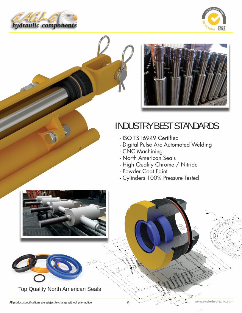
- ISO TS16949 Certified- Digital Pulse Arc Automated Welding- CNC Machining- North American Seals- High Quality Chrome / Nitride- Powder Coat Paint- Cylinders 100% Pressure Tested
INDUSTRY BEST STANDARDS
Top Quality North American Seals All product specifications are subject to change without prior notice.

6www.eagle-hydraulic.com
• Always wear eye protection and protective clothing when working on and around hydraulic systems.• Never exhaust hydraulic fluid under pressure to atmosphere. • Hydraulic fluid can reach high temperatures under normal operating conditions and can burn exposed
skin.• Fluid pressure can penetrate skin and cause death or serious injury, Wear proper protective clothing
when working on hydraulics.• Hydraulic devices should be properly “Locked-Out” or “Tagged-Out” before being worked on,
including the release of any stored energy or pressure. Ensure a mechanical locking device is in place to prevent injury or death.
• Eagle Hydraulic Components is not responsible for misuse or misapplication of product. • Do not use any heat-producing equipment such as oxyacetylene/gas torches and angle grinders on
sealed hydraulic cylinders. • Remove hydraulic oil from the cylinder before heating the cylinder.• Never operate a cylinder(or power unit) above recommended pressures. • Always use properly rated hoses and fittings. • Do not weld, add welded items, drill holes or otherwise modify the cylinder from its original design.• The hydraulic power unit may heat up during operation. The solenoids in the hydraulic power unit
become so hot during operation that you may sustain burns. You should wear heat-proof gloves or protective clothing.
All numbers given are nominal values and should be used for reference only.

7 www.eagle-hydraulic.com
• Installation and maintenance should be performed by qualified personnel. • Ensure that the bearing surfaces are properly lubricated (e.g. joint bearing, swivel bearing) when
operated.• Check leak-tightness and functional safety at frequent intervals. • Maximum permissible level of contamination by particles in accordance with ISO 4406.
CYLINDERS MAINTENANCE
CYLINDERS STORAGE• Always store indoors fully retracted in a clean dry area. • chromeplated rod protruding from the cylinder must be protected against potential corrosive
damage.Treat the entire surface with a preservative agent such as grease. • Smear the internal surfaces of eye/clevis bushes or bearings with grease.• We recommend that single-acting cylinders be protected against corrosion by directly adding
anti-corrosive oil to the unpressurized chamber. • Hydraulic cylinders must be filled with the same fluid the hydraulic system will operate with.
Assurances must be taken to assure complete filling of the cylinders with oil.• A relief valve shall be installed in the cylinder ports to allow FOR fluid expansion as the result of
increases in ambient temperatures. • Under these conditions, cylinders can be stored up to 12 months provided that they have not
yet been extended and retracted. • After 12 months, cylinders must be inspected and commercially available preservative agents
reapplied.
POWER UNITS, MOTORS AND PUMPS STORAGE• Pump and motor drive shafts should be protected with a preservative agent such as grease. All
ports should be capped if disconnected from the system.• Steel Power Unit reservoir should be filled to prevent corrosion since ambient temperature
change can results in moisture forming on the inside of the tank causing spot rusting and pitting of the tank surface.
• All Power Unit electrical connections (terminations) must be coated with corrosion inhebitors.• Power Supply should be disconnected from the power unit.• Single acting power unit should have the manual override valve open.
All product specifications are subject to change without prior notice.

8www.eagle-hydraulic.com
Chrome Rod Protection ExplainedChrome plated rod and bar products normally contain from 0.0005” minimum to 0.001” minimum hard chrome plate depending upon product specifications. This hard chrome coating is applied primarily for wear resistance though it does provide considerable corrosion resistance as well. Hard chrome plate de-posits with a “micro-cracked” structure. Although hard chrome plate cannot corrode, The metal substrate it adheres to can corrode if moisture and oxygen penetrate the chrome layer. The result is a blistering and flaking of the chrome plate deposit from the metal substrate. Once the shaft is assembled into a cylinder and put into service, the hydraulic fluid on the surface provides additional corrosion resistance which is normally sufficient to protect the shaft during its entire life. However, there are occasions when the shaft is not being worked and when the surface is exposed to a corrosive environment. For example, brand new equipment may be stored outside for a considerable period of time at a manufacturer’s plant, or an equipment dealer may hold inventory before it is sold. In these instances it is best to provide some ad-ditional corrosion protection.An inexpensive application of a rust preventative mixture can be applied to prevent corrosion and thereby preserve the quality of the hard chrome coating and the life of the cylinder.
PROTECTION OF NEW EQUIPMENTThe steps summarized below should be followed when protecting chrome plated shafting on new equip-ment:
1. Position the equipment as it will be stored, and identify all the exposed portions of the chrome plated shafts.
2. Clean dirt and dust from the exposed portions of the shafting using a dry cloth or a cloth which has been dampened with an appropriate solvent.
3. Prepare a mixture of 60% oil-based rust inhibitor and 40% Kerosene. Apply a thin coating of this mixture to the exposed surfaces of the chrome plated shafting. No. 1 fuel oil may be substituted for Kerosene. A cloth dipped in the mixture can be used to apply the coating.
4. Inspect the shaft surfaces after six months and apply additional corrosion preventative mixture. 5. If the equipment is to be moved and then stored again for an extended period of time, the steps above
should be repeated for all shafts that were stroked during the move.
PROTECTION OF OLDER EQUIPMENTOccasionally it may be necessary to store equipment that has seen some service. The procedure de-scribed above can be used for older equipment, but more careful cleaning of the shaft surfaces would be necessary. Also, there may be damage on some of the shaft surfaces which will require additional protection. Under no circumstances should sandpaper or other abrasives be used to clean the surfaces. Plastic or copper wool in combination with an appropriate solvent will remove most of the dirt. After the surface is clean it should be inspected for damage to the chrome plate. If damage is detected, more frequent ap-plication of the corrosion preventative will be necessary to prevent corrosion during storage
All numbers given are nominal values and should be used for reference only.
9 www.eagle-hydraulic.com
UTILI
TY W
ELDE
D HYD
RAUL
IC CY
LINDE
RS
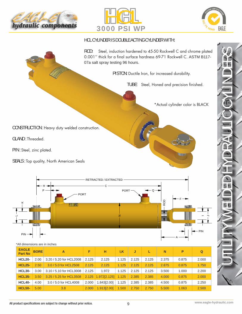
HCL3000 PSI WP
EAGLE Part No BORE A F H I,K J L N P Q
HCL20- 2.00 3.20 / 5.20 for HCL2008 2.125 2.125 1.125 2.125 2.125 2.375 0.875 2.000
HCL25- 2.50 3.0 / 5.0 for HCL2508 2.125 2.125 1.125 2.125 2.125 2.875 0.875 1.750
HCL30- 3.00 3.10 / 5.10 for HCL3008 2.125 1.972 1.125 2.125 2.125 3.500 1.000 2.200
HCL35- 3.50 3.25 / 5.25 for HCL3508 2.125 1.972[2.125] 1.125 2.385 2.385 4.000 0.875 2.000
HCL40- 4.00 3.0 / 5.0 for HCL4008 2.000 1.843[2.00] 1.125 2.385 2.385 4.500 0.875 2.250
HCL50- 5.00 3.8 2.000 1.913[2.00] 1.500 2.750 2.750 5.500 1.063 2.500
HCL CYLINDER IS DOUBLE ACTING CYLINDER WITH:
ROD: Steel, induction hardened to 45-50 Rockwell C and chrome plated 0.001’’ thick for a final surface hardness 69-71 Rockwell C. ASTM B117-07a salt spray testing 96 hours.
PISTON: Ductile Iron, for increased durability.
TUBE: Steel, Honed and precision finished.
RETRACTED / EXTRACTED
N
H
L
K
A
I J
F
RO
D
PINPIN
C
PORTPORTP Q
CONSTRUCTION : Heavy duty welded construction.
GLAND : Threaded.
PIN : Steel, zinc plated.
SEALS : Top quality, North American Seals
*Actual cylinder color is BLACK
*All dimensions are in inches
All product specifications are subject to change without prior notice.

10www.eagle-hydraulic.com
UTILI
TY W
ELDE
D HYD
RAUL
IC CY
LINDE
RSHCL
3000 PSI WP
SEA
L K
IT N
UM
BER
EAG
LE P
art N
o.SE
AL
KIT
NU
MB
ERH
CL2
0-SK
-HBU
/CL-
2012
50
HC
L25-
SK-H
BU/C
L-25
1500
HC
L30-
SK-H
BU/C
L-30
1500
HC
L35-
SK-H
BU/C
L-35
1750
HC
L40-
SK-H
BU/C
L-40
2000
HC
L50-
SK-H
BU/C
L-50
2500
ITEM
DES
CR
IPTI
ON
QTY
1Ba
rrel
1
2R
od1
3Pi
ston
1
4G
land
1
5Pi
n2
6H
air P
in4
7Pl
astic
Plu
g2
8Pl
ug O
-Rin
g (S
AE)
2
9St
over
Loc
knut
1
10W
iper
1
11R
od S
eal
1
12G
land
Bac
k-U
p R
ing
1
13G
land
O-R
ing
1
14R
od B
ack-
Up
Rin
g2
15R
od O
-Rin
g1
16Pi
ston
Sea
l2
All numbers given are nominal values and should be used for reference only.

11 www.eagle-hydraulic.com
UTILI
TY W
ELDE
D HYD
RAUL
IC CY
LINDE
RS
HCL3000 PSI WP
PART No. STROKE RODDIAMETER
DIMENSIONSC
MAX FORCE
LBS PO
RT
PIN WEIGHT (LBS)RETRACTED EXTRACTED
HC
L 2"
BO
RE
3000
PS
I WP
HCL2004 4"
1 1/4”
14 1/4” 18 1/4” 8.5”
9425
SA
E#6
N
PT
Ava
ilab
le
1"
14HCL2006 6" 16 1/4” 22 1/4” 10.5” 15HCL2008 8" 20 1/4” 28 1/4” 12.5” 17HCL2010 10" 20 1/4” 30 1/4” 14.5” 17HCL2012 12" 22 1/4” 34 1/4’’ 16.5” 19HCL2014 14" 24 1/4” 38 1/4” 18.5” 21HCL2016 16" 26 1/4” 42 1/4” 20.5” 23HCL2018 18" 28 1/4” 46 1/4” 22.5 24
HCL2020 20" 30 1/4” 50 1/4” 24.5” 26HCL2024 24" 34 1/4” 58 1/4” 28.5” 28
HCL2028 28" 38 1/4” 66 1/4” 32.5” 34
HCL2030 30" 40 1/4” 70 1/4” 34.5” 35HCL2032 32" 42 1/4” 74 1/4” 36.5” 36HCL2034 34" 44 1/4” 78 1/4” 38.5” 39HCL2036 36" 46 1/4” 82 1/4” 40.5” 40
HC
L 2.
5" B
OR
E30
00 P
SI W
P
HCL2504 4"
1 1/2”
14 1/4” 18 1/4” 8.56”
14726
SA
E#8
N
PT
Ava
ilab
le
1"
17
HCL2506 6" 16 1/4” 22 1/4” 10.56” 20
HCL2508 8" 20 1/4” 28 1/4” 12.56” 22HCL2510 10" 20 1/4” 30 1/4” 14.56” 23HCL2512 12" 22 1/4” 34 1/4’’ 16.56” 25HCL2514 14" 24 1/4” 38 1/4” 18.56” 28HCL2516 16" 26 1/4” 42 1/4” 20.56” 30HCL2518 18" 28 1/4” 46 1/4” 22.56” 31HCL2520 20" 30 1/4” 50 1/4” 24.56” 34HCL2524 24" 34 1/4” 58 1/4” 28.56” 38HCL2528 28" 38 1/4” 66 1/4” 32.56” 42HCL2530 30" 40 1/4” 70 1/4” 34.56” 45HCL2532 32" 42 1/4” 74 1/4” 36.56” 46HCL2534 34" 44 1/4” 78 1/4” 38.56” 50HCL2536 36" 46 1/4” 82 1/4” 40.56” 51
HC
L 3"
BO
RE
3000
PS
I WP
HCL3004 4"
1 1/2”
14 1/4” 18 1/4” 9.04”
21205
SA
E#8
N
PT
Ava
ilab
le
1"
23HCL3006 6" 16 1/4” 22 1/4” 11.04” 26
HCL3008 8" 20 1/4” 28 1/4” 13.04” 28HCL3010 10" 20 1/4” 30 1/4” 15.04” 29HCL3012 12" 22 1/4” 34 1/4” 17.04” 30HCL3014 14" 24 1/4” 381/4” 19.04” 32HCL3016 16" 26 1/4” 42 1/4” 21.04” 36HCL3018 18" 28 1/4” 46 1/4” 23.04” 39HCL3020 20" 30 1/4” 50 1/4” 25.04” 42HCL3024 24" 34 1/4” 58 1/4” 29.04” 46HCL3028 28" 38 1/4” 66 1/4” 33.04” 51
HCL3030 30" 40 1/4” 70 1/4” 35.04” 54
HCL3032 32" 42 1/4” 74 1/4” 37.04” 56
HCL3034 34" 44 1/4” 781/4” 39.04” 59
HCL3036 36" 46 1/4” 82 1/4” 41.04” 61
All product specifications are subject to change without prior notice.
12www.eagle-hydraulic.com
UTILI
TY W
ELDE
D HYD
RAUL
IC CY
LINDE
RSHCL
3000 PSI WP
BBBC
N
RO
D
FPORT PORT
RETRACTED / EXTRACTED
J
L
A
B
C
D
E
QP
PART No. STROKE ROD DIAMETER
DIMENSIONSC
MAXFORCE
LBS PO
RT
PIN WEIGHT (LBS)RETRACTED EXTRACTED
HC
L 3.
5" B
OR
E
3000
PS
I WP
HCL3504 4"
1 3/4”
14 1/4” 18 1/4” 8.92”
28863
SA
E#8
N
PT
Ava
ilab
le
1”
1 1
/4”
Ava
ilab
le
26HCL3506 6" 16 1/4” 22 1/4” 10.92” 29
HCL3508 8" 20 1/4” 28 1/4” 12.92” 33HCL3510 10" 20 1/4” 30 1/4” 14.92” 36HCL3512 12" 22 1/4” 34 1/4’’ 16.92” 39HCL3514 14" 24 1/4” 38 1/4” 18.92” 41HCL3516 16" 26 1/4” 42 1/4” 20.92” 45HCL3518 18" 28 1/4” 46 1/4” 22.92” 48HCL3520 20" 30 1/4” 50 1/4” 24.92” 52HCL3524 24" 34 1/4” 58 1/4” 28.92” 55HCL3528 28" 38 1/4” 66 1/4” 32.92” 62
HCL3530 30" 40 1/4” 70 1/4” 34.92” 66
HCL3532 32" 42 1/4” 74 1/4” 36.92” 70HCL3534 34" 44 1/4” 78 1/4” 38.92” 73HCL3536 36" 46 1/4” 82 1/4” 40.92” 77
HC
L 4"
BO
RE
3000
PS
I WP
HCL4004 4"
2"
14 1/4” 18 1/4” 9.27”
37700
SA
E#8
N
PT
Ava
ilab
le
1”
1
1/2
” A
vaila
ble
31HCL4006 6" 16 1/4” 22 1/4” 11.27” 36HCL4008 8" 20 1/4” 28 1/4” 13.27” 41HCL4010 10" 20 1/4” 30 1/4” 15.27” 46HCL4012 12" 22 1/4” 34 1/4” 17.27” 47
HCL4014 14" 24 1/4” 38 1/4” 19.27” 50HCL4016 16" 26 1/4” 42 1/4” 21.27” 53HCL4018 18" 28 1/4” 46 1/4” 23.27” 56
HCL4020 20" 30 1/4” 50 1/4” 25.27” 61
HCL4024 24" 34 1/4” 58 1/4” 29.27” 66HCL4028 28" 38 1/4” 66 1/4” 33.27” 77HCL4030 30" 40 1/4” 70 1/4” 35.27” 81HCL4032 32" 42 1/4” 74 1/4” 37.27” 87HCL4034 34" 44 1/4” 78 1/4” 39.27” 90HCL4036 36" 46 1/4” 82 1/4” 41.27” 94
HC
L 5"
BO
RE
3000
PS
I WP
HCL5004 4"
2 1/2”
16 1/4” 20 1/4” 10.5”
58905
SA
E#8
S
AE
#1
2 A
vail.
NP
T A
vail.
1”
1 1
/2”
Ava
ilab
le
63HCL5006 6" 18 1/4” 24 1/4” 12.5” 67HCL5008 8" 20 1/4” 28 1/4” 14.5” 71HCL5010 10" 22 1/4” 32 1/4” 16.5” 76HCL5012 12" 24 1/4” 36 1/4” 18.5” 80HCL5014 14" 26 1/4” 40 1/4” 20.5” 84HCL5016 16" 28 1/4” 44 1/4” 22.5” 89HCL5018 18" 30 1/4” 48 1/4” 24.5” 93HCL5020 20" 32 1/4” 52 1/4” 26.5” 98
HCL5024 24" 36 1/4” 60 1/4” 30.5” 106HCL5028 28" 40 1/4” 68 1/4” 34.5” 115HCL5030 30" 42 1/4” 72 1/4” 36.5” 120HCL5032 32" 44 1/4” 76 1/4” 38.5” 124HCL5034 34" 46 1/4” 80 1/4” 40.5” 129
HCL5036 36" 48 1/4” 84 1/4” 42.5” 133
All numbers given are nominal values and should be used for reference only.

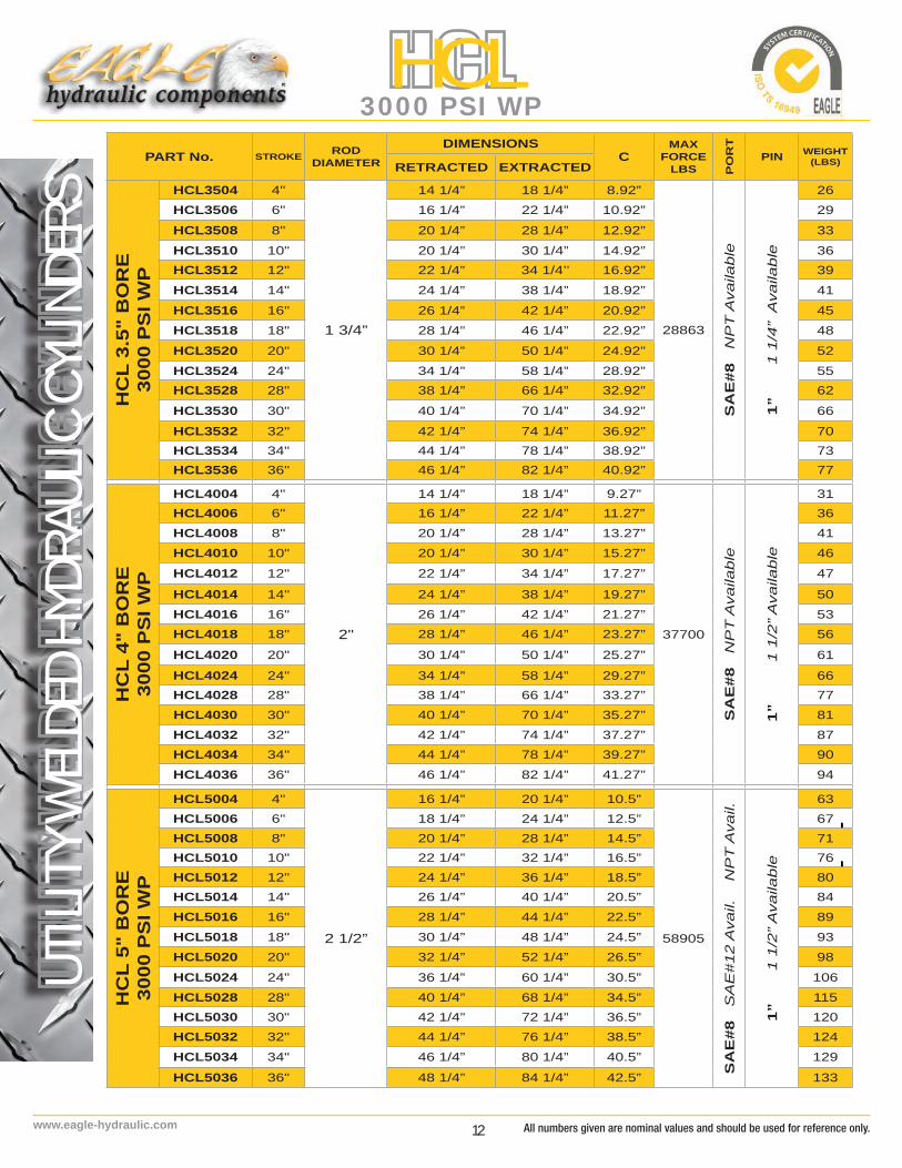
13 www.eagle-hydraulic.com
UTILI
TY W
ELDE
D HYD
RAUL
IC CY
LINDE
RS
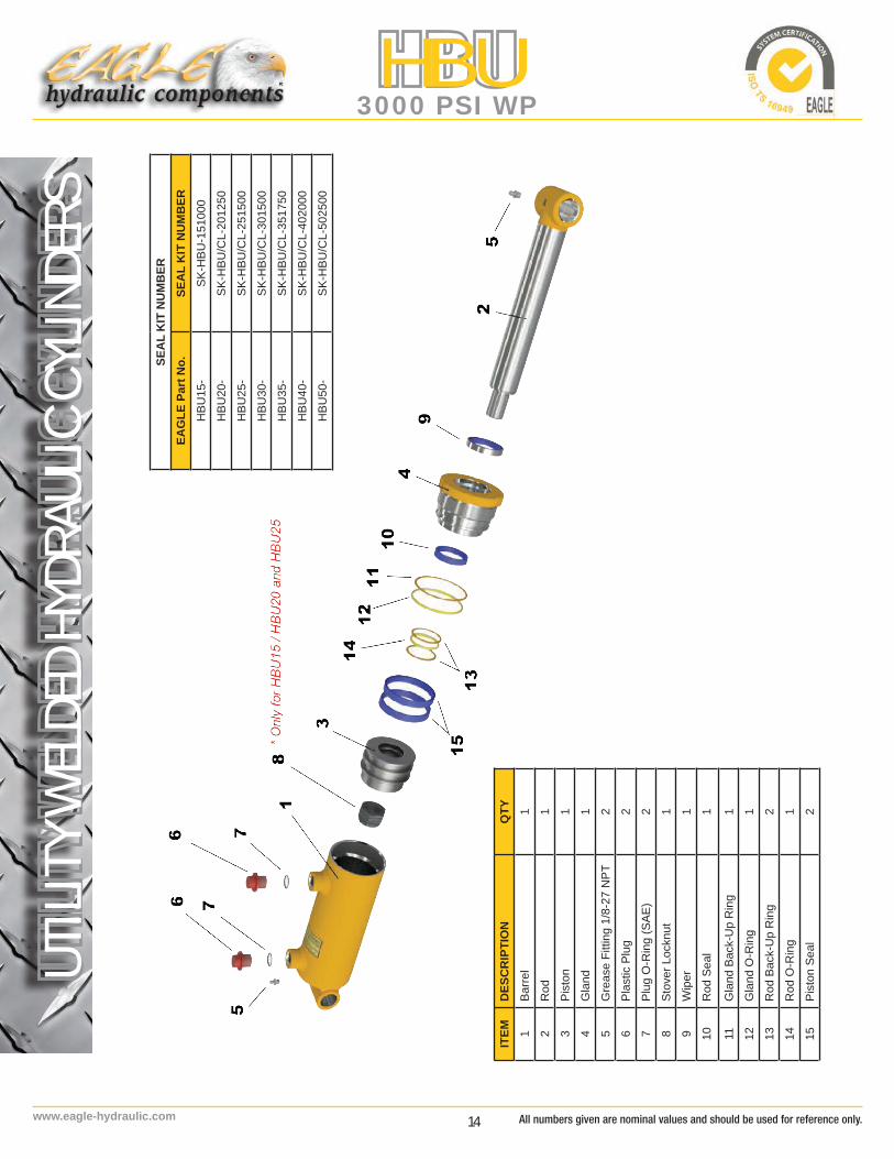
HBU3000 PSI WP
BBBC
N
RO
D
FPORT PORT
RETRACTED / EXTRACTED
J
L
A
B
C
D
E
QP
EAGLE Part No BORE ROD A C, E B, D J L N P Q
HBU15- 1.50 1.00 2.70 1.250 0.750 2.00 2.25 1,875 0.875 2.200
HBU20- 2.00 1.25 2.80 1.500 1.00 2.25 2.75 2.375 0.875 2.000
HBU25- 2.50 1.50 2.65 1.500 1.000 2.25 3.25 2.875 0.875 2.000
HBU30- 3.00 1.50 2.20 1.500 1.000 2.25 3.75 3.50 1.000 2.200
HBU35- 3.50 1.75 4.10 2.000 1.250 2.25 4.25 4.00 0.875 2.000
HBU40- 4.00 2.00 3.60 2.250 1.500 2.50 4.75 4.500 1.000 2.250
HBU50- 5.00 2.50 4.50 2.500 1.750 3.25 5.75 5.500 1.000 2.500
HBU CYLINDER IS DOUBLE ACTING CYLINDER WITH:
ROD: Steel, induction hardened to 45-50 Rockwell C and chrome plated 0.001’’ thick for a final surface hardness 69-71 Rockwell C. ASTM B117-07a salt spray testing 96 hours.
PISTON: Ductile Iron, for increased durability.
TUBE: Steel, Honed and precision finished.
CONSTRUCTION : Heavy duty welded construction.
GLAND : Threaded.
SEALS: Top quality, North American Seals
*Actual cylinder color is BLACK
*All dimensions are in inches
All product specifications are subject to change without prior notice.
14www.eagle-hydraulic.com
UTILI
TY W
ELDE
D HYD
RAUL
IC CY
LINDE
RSHBU
3000 PSI WP
SEA
L K
IT N
UM
BER
EAG
LE P
art N
o.SE
AL
KIT
NU
MB
ERH
BU15
-SK
-HBU
-151
000
HBU
20-
SK-H
BU/C
L-20
1250
HBU
25-
SK-H
BU/C
L-25
1500
HBU
30-
SK-H
BU/C
L-30
1500
HBU
35-
SK-H
BU/C
L-35
1750
HBU
40-
SK-H
BU/C
L-40
2000
HBU
50-
SK-H
BU/C
L-50
2500
ITEM
DES
CR
IPTI
ON
QTY
1Ba
rrel
1
2R
od1
3Pi
ston
1
4G
land
1
5G
reas
e Fi
tting
1/8
-27
NPT
2
6Pl
astic
Plu
g2
7Pl
ug O
-Rin
g (S
AE)
2
8St
over
Loc
knut
1
9W
iper
1
10R
od S
eal
1
11G
land
Bac
k-U
p R
ing
1
12G
land
O-R
ing
1
13R
od B
ack-
Up
Rin
g2
14R
od O
-Rin
g1
15Pi
ston
Sea
l2
All numbers given are nominal values and should be used for reference only.

15 www.eagle-hydraulic.com
UTILI
TY W
ELDE
D HYD
RAUL
IC CY
LINDE
RS
HBU3000 PSI WP
HB
U 1
.5"
BO
RE
30
00 P
SI W
P
PART No. STROKE ROD DIAMETER
DIMENSIONSF
MAXFORCE
LBS PO
RT
PIN WEIGHT (LBS)RETRACTED EXTRACTED
HBU1504 4"
1"
12" 16" 8.5”
5300
SA
E#4
NP
T A
vail.
3/4"
9
HBU1506 6" 14" 20" 10.5” 10
HBU1508 8" 16" 24" 12.5” 11
HBU1510 10" 18" 28" 14.5” 13
HBU1512 12" 20" 32" 16.5” 14
HBU1514 14" 22" 36" 18.5” 15
HBU1516 16" 24" 40" 20.5” 17
HB
U 2
" B
OR
E
3000
PS
I WP
HBU2004 4”
1 1/4”
12” 16” 8.5”
9425
SA
E#6
N
PT
Ava
ilabl
e
1"
13
HBU2006 6” 14” 20” 10.5” 14
HBU2008 8" 16" 24" 12.5” 15
HBU2010 10" 18" 28" 14.5” 15
HBU2012 12" 20" 32" 16.5” 16
HBU2014 14" 22" 36" 18.5” 17
HBU2016 16" 24" 40" 20.5” 22
HBU2018 18" 26" 44" 22.5” 22
HBU2020 20" 28" 48" 24.5” 23
HBU2024 24" 32" 56" 28.5” 28
HBU2028 28" 36" 64" 32.5” 31
HBU2030 30" 38" 68" 34.5” 34
HBU2032 32" 40" 72" 36.5” 36
HBU2036 36" 44" 80" 40.5” 39
HBU2040 40" 48" 88" 44.5” 40
HBU2048 48" 56" 104" 52.5” 50
HB
U 2
.5"
BO
RE
300
0PS
I WP
HBU2504 4”
1 1/2”
12” 16” 8.56”
14726
SAE#
8 N
PT
Ava
ilabl
e
1"
17
HBU2506 6” 14” 20” 10.56” 18
HBU2508 8" 16" 24" 12.56” 19
HBU2510 10" 18" 28" 14.56” 22
HBU2512 12" 20" 32" 16.56” 24
HBU2514 14" 22" 36" 18.56” 26
HBU2516 16" 24" 40" 20.56” 30
HBU2518 18" 26" 44" 22.56” 31
HBU2520 20" 28" 48" 24.56” 32
HBU2524 24" 32" 56" 28.56” 37
HBU2528 28" 36" 64" 32.56” 42
HBU2530 30" 38" 68" 34.56” 44
HBU2532 32" 40" 72" 36.56” 46
HBU2536 36" 44" 80" 40.56” 50
HBU2540 40" 48" 88" 44.56” 55
HBU2548 48" 56" 104" 52.56” 62
All product specifications are subject to change without prior notice.

16www.eagle-hydraulic.com
UTILI
TY W
ELDE
D HYD
RAUL
IC CY
LINDE
RSHBU
3000 PSI WPH
BU
3”
BO
RE
3000
PS
I WP
PART No. STROKE ROD DIAMETER
DIMENSIONSF
MAXFORCE
LBS PO
RT
PIN WEIGHT (LBS)
RETRACTED EXTRACTED
HBU3004 4”
1 1/2”
12” 16” 9.04”
21205
SAE#
8 N
PT
Ava
ilabl
e
1”
24
HBU3006 6” 14” 20” 11.04” 25
HBU3008 8” 16” 24” 13.04” 26
HBU3010 10” 18” 28” 15.04” 28
HBU3012 12” 20” 32” 17.04” 29
HBU3014 14” 22” 36” 19.04” 31
HBU3016 16” 24” 40” 21.04” 32
HBU3018 18” 26” 44” 23.04” 36
HBU3020 20” 28” 48” 25.04” 39
HBU3024 24” 32” 56” 29.04” 42
HBU3028 28” 36” 64” 33.04” 48
HBU3030 30” 38” 68” 35.04” 52
HBU3032 32” 40” 72” 37.04” 56
HBU3036 36" 44" 80" 41.04” 60
HBU3040 40" 48" 88" 45.04” 65
HBU3048 48" 56" 104" 53.04” 71
HB
U 3
.5"
BO
RE
3000
PS
I WP
HBU3504 4”
1 3/4”
14” 18” 8.92”
28863
SAE#
8 N
PT
Ava
ilabl
e
1 1/4”
28
HBU3506 6” 16” 22” 10.92” 31
HBU3508 8" 18" 26" 12.92” 33
HBU3510 10" 20" 30" 14.92” 36
HBU3512 12" 22" 34" 16.92” 39
HBU3514 14" 24" 38" 18.92” 41
HBU3516 16" 26" 42" 20.92” 45
HBU3518 18" 28" 46" 22.92” 48
HBU3520 20" 30" 50" 24.92” 51
HBU3524 24" 34" 58" 28.92” 56
HBU3528 28" 38" 66" 32.92” 60
HBU3530 30" 40" 70" 34.92” 64
HBU3532 32" 42" 74" 36.92” 68
HBU3536 36" 46" 82" 40.92” 77
HBU3540 40" 50" 90" 44.92” 81
HBU3548 48" 58" 106" 52.92” 85
All numbers given are nominal values and should be used for reference only.

17 www.eagle-hydraulic.com
UTILI
TY W
ELDE
D HYD
RAUL
IC CY
LINDE
RS
HBU3000 PSI WP
PART No. STROKE ROD DIAMETER
DIMENSIONSF
MAXFORCE
LBS PO
RT
PIN WEIGHT (LBS)
RETRACTED EXTRACTED
HB
U 4
" B
OR
E30
00P
SI W
P
HBU4004 4”
2"
14” 18” 9.27”
37700
SAE#
8 N
PT
Ava
ilabl
e
1 1/2”
35
HBU4006 6” 16” 22” 11.27” 38
HBU4008 8" 18" 26" 13.27” 41
HBU4010 10" 20" 30" 15.27” 45
HBU4012 12" 22" 34" 17.27” 48
HBU4014 14" 24" 38" 19.27” 52
HBU4016 16" 26" 42" 21.27” 55
HBU4018 18" 28" 46" 23.27” 59
HBU4020 20" 30" 50" 25.27” 63
HBU4024 24" 34" 58" 29.27” 68
HBU4028 28" 38" 66" 33.27” 77
HBU4030 30" 40" 70" 35.27” 81
HBU4032 32" 42" 74" 37.27” 84
HBU4036 36" 46" 82" 41.27” 92
HBU4040 40" 50" 90" 45.27” 99
HBU4048 48" 58" 106" 53.27 114
HB
U 5
" B
OR
E 3
000P
SI W
P
HBU5004 4”
2 1/2”
16” 20” 10.5”
58905
SA
E#8
S
AE
#1
2 A
vaila
ble
N
PT
Ava
ilab
le
1 3/4”
63
HBU5006 6” 18” 24” 12.5” 67
HBU5008 8" 20" 28" 14.5” 71
HBU5010 10" 22" 32" 16.5” 76
HBU5012 12" 24" 36" 18.5” 80
HBU5014 14" 26" 40" 20.5” 81
HBU5016 16" 28" 44" 22.5” 89
HBU5018 18" 30" 48" 24.5” 93
HBU5020 20" 32" 52" 26.5” 98
HBU5024 24" 36" 60" 30.5” 106
HBU5028 28" 40" 68" 34.5” 115
HBU5030 30" 42" 72" 36.5” 120
HBU5032 32" 44" 76" 38.5” 124
HBU5036 36" 48" 84" 42.5” 133
HBU5040 40" 52" 92" 46.5” 142
HBU5048 48" 60" 108" 54.5” 159
All product specifications are subject to change without prior notice.

18www.eagle-hydraulic.com
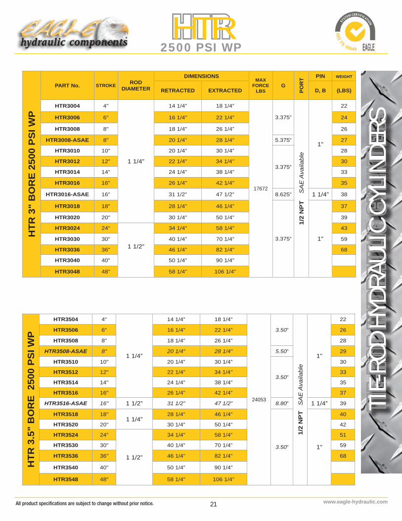
TIE-R
OD H
YDRA
ULIC
CYL
INDE
RSHTR
2500 PSI WP
EAGLE Part No BORE C E F H I,K J L M N T
HTR20- 2.00 2.000 2.000 2.125 2.06 1.125 2.500 2.375 1-1/8-12-UNF 2.375 M10
HTR25- 2.50 2.000 2.000 2.125 2.06 1.125 2.500 2.500 1-1/8-12-UNF 2.875 M10
HTR30- 3.00 2.250 2.000 2.125 2. 06 1.125 2.625 2.500 1-1/4-12-UNF 3.375 M12
HTR35- 3.50 2.250 2.250 2.1 25 2.06 1.125 2.625 2.500 1-1/4-12-UNF 3.875 M16
HTR40- 4.00 2.250 2.250 2.125 2.06 1.125 2.625 2.625 1-1/4-12-UNF 4.375 M16
HTR50- 5.00 2.500 3.000 2.125 2.250 1.250 2.875 3.500 1-1/2-12-UNF 5.500 M20
HTR TIE-ROD CYLINDER IS DOUBLE ACTING CYLINDER WITH:
ROD: Steel, superior and hard, chrome plated 0.001” thick for a final surface hardness 69-71 Rockwell C
PISTON: Ductile Iron, for increased durability.
TUBE: Steel, Honed and precision finished for extended seal life STEEL TIE-ROD: High tensile strength to prevent stretching
END CAP : With 2 ports 90° to eachother for greater flexibility of assembly
ATTACHMENT: Ductile Iron, threaded female clevis,adjustable with locking bolt
PIN: Steel, zinc plated
SEALS: Top quality, North American Seals
PAINT: High quality paint for corrosion resistance (Standard color: Black)
RETRACTED / EXTRACTED
KL
H
N
RO
D
T
PORT PORTG
F
I J
M
ØC
ØBØDØE
*Actual cylinder color is BLACK
*All dimensions are in inches
All numbers given are nominal values and should be used for reference only.

19 www.eagle-hydraulic.com
TIE-R
OD H
YDRA
ULIC
CYL
INDE
RS
HTR2500 PSI WP
SEA
L K
IT N
UM
BER
EAG
LE P
art N
o.SE
AL
KIT
NU
MB
ERH
TR20
-SK
-HTR
2011
25
HTR
25-
SK-H
TR25
1125
HTR
30-
SK-H
TR30
1250
HTR
35-
SK-H
TR35
1250
HTR
40-
SK-H
TR40
1250
HTR
50-
SK-H
TR50
2000
ITEM
DES
CR
IPTI
ON
QTY
1Ba
rrel (
Tube
)1
2R
od1
3En
d C
ap1
4G
land
1
5Pi
ston
1
6Th
read
ed C
levi
s1
7Ti
e-R
od4
8Ti
e-R
od N
ut8
9Pi
n2
10H
air P
in4
11Pl
astic
Plu
g N
PT2
ITEM
DES
CR
IPTI
ON
QTY
12St
eel P
lug
NPT
1
13C
levi
s Lo
ck B
olt
1
14C
levi
s Lo
ck N
ut1
15St
over
Loc
knut
1
16R
od O
-Rin
g1
17Pi
ston
Sea
l (O
-Rin
g)2
18Pi
ston
Sea
l (Ba
ck-U
p)1
19W
iper
1
20R
od S
eal
1
21G
land
O-R
ing
2
22G
land
Bac
k-U
p R
ing
2
All product specifications are subject to change without prior notice.

20www.eagle-hydraulic.com
TIE-R
OD H
YDRA
ULIC
CYL
INDE
RSHTR
2500 PSI WP
PART No. STROKE ROD DIAMETER
DIMENSIONS MAXFORCE
LBSG
PO
RT PIN WEIGHT
RETRACTED EXTRACTED D, B (LBS)
HTR
2"
BO
RE
2500
PSI
WP
HTR2004 4"
1 1/8”
14 1/4” 18 1/4”
7854
3.375"
3/8
NP
T S
AE
Ava
ilabl
e
1"
14
HTR2006 6" 16 1/4” 22 1/4” 16
HTR2008 8" 18 1/4” 26 1/4” 17
HTR2008-ASAE 8" 20 1/4” 28 1/4” 5.375" 18
HTR2010 10" 20 1/4” 30 1/4”
3.375"
19
HTR2012 12" 22 1/4” 34 1/4’’ 20
HTR2014 14" 24 1/4” 38 1/4” 22
HTR2016 16" 26 1/4” 42 1/4” 24
HTR2018 18" 28 1/4” 46 1/4” 26
HTR2020 20" 30 1/4” 50 1/4” 27
HTR2024 24" 34 1/4” 58 1/4” 30
HTR2030 30" 40 1/4” 70 1/4” 35
HTR2036 36" 46 1/4” 82 1/4” 40
HTR2040 40" 50 1/4” 90 1/4”
HTR2048 48" 58 1/4” 106 1/4”
HTR
2.5
" B
OR
E 25
00 P
SI W
P
HTR2504 4"
1 1/8”
14 1/4” 18 1/4”
12272
3.375"3/
8 N
PT
SA
E A
vaila
ble
1"
16
HTR2506 6" 16 1/4” 22 1/4” 18
HTR2508 8" 18 1/4” 26 1/4” 19
HTR2508-ASAE 8" 20 1/4” 28 1/4” 5.375" 20
HTR2510 10" 20 1/4” 30 1/4”
3.375"
21
HTR2512 12" 22 1/4” 34 1/4” 23
HTR2514 14" 24 1/4” 38 1/4” 25
HTR2516 16" 26 1/4” 42 1/4” 27
HTR2518 18" 28 1/4” 46 1/4” 28
HTR2520 20" 30 1/4” 50 1/4” 30
HTR2524 24" 34 1/4” 58 1/4” 34
HTR2530 30"
1 1/4”
40 1/4” 70 1/4” 45
HTR2536 36" 46 1/4” 82 1/4” 56
HTR2540 40" 50 1/4” 90 1/4”
HTR2548 48" 58 1/4” 106 1/4”
All numbers given are nominal values and should be used for reference only.
21 www.eagle-hydraulic.com
TIE-R
OD H
YDRA
ULIC
CYL
INDE
RS
HTR2500 PSI WP
HTR
3.5
" B
OR
E 2
500
PSI W
P
HTR3504 4"
1 1/4”
14 1/4” 18 1/4”
24053
3.50"
1/2
NP
T S
AE
Ava
ilabl
e
1"
22
HTR3506 6" 16 1/4” 22 1/4” 26
HTR3508 8" 18 1/4” 26 1/4” 28
HTR3508-ASAE 8" 20 1/4” 28 1/4” 5.50" 29
HTR3510 10" 20 1/4” 30 1/4”
3.50"
30
HTR3512 12" 22 1/4” 34 1/4’’ 33
HTR3514 14" 24 1/4” 38 1/4” 35
HTR3516 16" 26 1/4” 42 1/4” 37
HTR3516-ASAE 16" 1 1/2” 31 1/2” 47 1/2” 8.80" 1 1/4” 39
HTR3518 18"1 1/4”
28 1/4” 46 1/4”
3.50" 1"
40
HTR3520 20" 30 1/4” 50 1/4” 42
HTR3524 24"
1 1/2”
34 1/4” 58 1/4” 51
HTR3530 30" 40 1/4” 70 1/4” 59
HTR3536 36" 46 1/4” 82 1/4” 68
HTR3540 40" 50 1/4” 90 1/4”
HTR3548 48" 58 1/4” 106 1/4”
HTR
3"
BO
RE
2500
PSI
WP
PART No. STROKE ROD DIAMETER
DIMENSIONSMAX
FORCELBS
G
POR
T PIN WEIGHT
RETRACTED EXTRACTED D, B (LBS)
HTR3004 4"
1 1/4”
14 1/4” 18 1/4”
17672
3.375"
1/2
NP
T
SA
E A
vaila
ble
1"
22
HTR3006 6" 16 1/4” 22 1/4” 24
HTR3008 8" 18 1/4” 26 1/4” 26
HTR3008-ASAE 8" 20 1/4” 28 1/4” 5.375" 27
HTR3010 10" 20 1/4” 30 1/4”
3.375"
28
HTR3012 12" 22 1/4” 34 1/4’’ 30
HTR3014 14" 24 1/4” 38 1/4” 33
HTR3016 16" 26 1/4” 42 1/4” 35
HTR3016-ASAE 16" 31 1/2” 47 1/2” 8.625" 1 1/4” 38
HTR3018 18" 28 1/4” 46 1/4”
3.375" 1"
37
HTR3020 20" 30 1/4” 50 1/4” 39
HTR3024 24"
1 1/2”
34 1/4” 58 1/4” 43
HTR3030 30" 40 1/4” 70 1/4” 59
HTR3036 36" 46 1/4” 82 1/4” 68
HTR3040 40" 50 1/4” 90 1/4”
HTR3048 48" 58 1/4” 106 1/4”
All product specifications are subject to change without prior notice.

22www.eagle-hydraulic.com
TIE-R
OD H
YDRA
ULIC
CYL
INDE
RSHTR
2500 PSI WPH
TR 4
" B
OR
E 25
00 P
SI W
P
PART No. STROKE ROD DIAMETER
DIMENSIONS MAXFORCE
LBSG
POR
T PIN WEIGHT
RETRACTED EXTRACTED D, B (LBS)
HTR4004 4"
1 1/4”
14 1/4” 18 1/4”
31416
3.375"
1/2
NP
T S
AE
Ava
ilabl
e
1"
30
HTR4006 6" 16 1/4” 22 1/4” 33
HTR4008 8" 18 1/4” 26 1/4” 35
HTR4008-ASAE 8" 20 1/4” 28 1/4” 5.375" 36
HTR4010 10" 20 1/4” 30 1/4”
3.375"
37
HTR4012 12" 22 1/4” 34 1/4” 40
HTR4014 14" 24 1/4” 38 1/4” 42
HTR4016 16" 26 1/4” 42 1/4” 48
HTR4016-ASAE 16" 2" 31 1/2” 47 1/2” 8.625" 1 1/4” 64
HTR4018 18"
1 1/2”
28 1/4” 46 1/4”
3.375" 1"
51
HTR4020 20" 30 1/4” 50 1/4” 53
HTR4024-150 24" 34 1/4” 58 1/4” 59
HTR4024-175 24" 1 3/4” 34 1/4” 58 1/4” 64
HTR4024-200 24"
2”
34 1/4” 58 1/4” 70
HTR4030 30" 40 1/4” 70 1/4” 87
HTR4036 36" 46 1/4” 82 1/4” 98
HTR4040 40" 50 1/4” 90 1/4”
HTR4048 48" 58 1/4” 106 1/4”
HTR
5"
BO
RE
150
0 PS
I W
P
HTR5004 4"
1 1/2”
16 1/4” 20 1/4”
29452
3.75"1/
2 N
PT
SA
E A
vaila
ble
1"
53
HTR5006 6" 18 1/4” 24 1/4” 55
HTR5008 8" 20 1/4” 28 1/4” 64
HTR5008-ASAE 8" 22 1/4” 30 1/4” 5.75" 66
HTR5010 10" 22 1/4” 32 1/4”
3.75"
68
HTR5012 12"
2"
24 1/4” 36 1/4’’
1 1/4”
77
HTR5014 14" 26 1/4” 40 1/4” 82
HTR5016 16" 28 1/4” 44 1/4” 87
HTR5016-ASAE 16" 31 1/2” 47 1/2” 7.00" 90
HTR5018 18" 30 1/4” 48 1/4”
3.75"
92
HTR5020 20" 32 1/4” 52 1/4” 93
HTR5024 24" 36 1/4” 60 1/4” 106
HTR5030 30" 42 1/4” 72 1/4” 121
HTR5036 36" 48 1/4” 84 1/4” 136
HTR5040 40" 52 1/4” 90 1/4” 145
HTR5048 48" 60 1/4” 106 1/4” 150
All numbers given are nominal values and should be used for reference only.
23 www.eagle-hydraulic.com
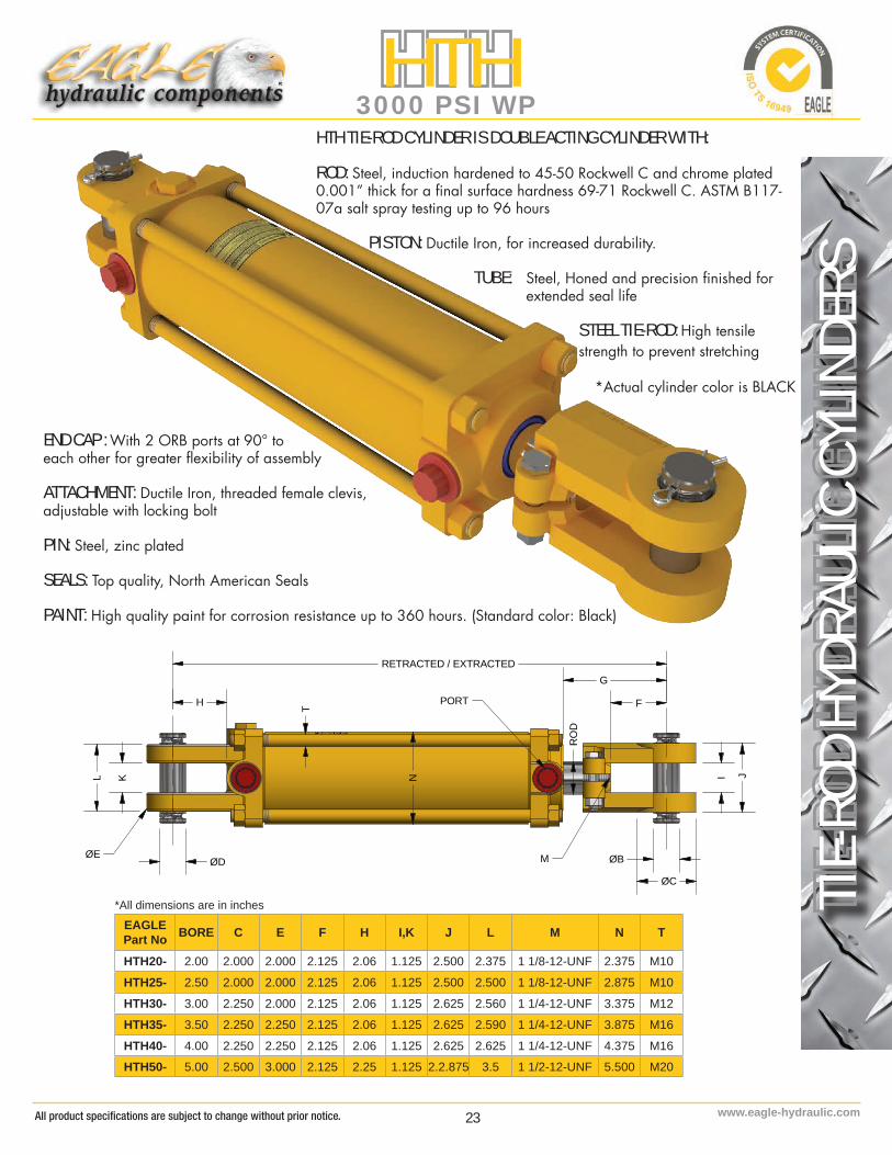
TIE-R
OD H
YDRA
ULIC
CYL
INDE
RS
HTH3000 PSI WP
EAGLE Part No BORE C E F H I,K J L M N T
HTH20- 2.00 2.000 2.000 2.125 2.06 1.125 2.500 2.375 1 1/8-12-UNF 2.375 M10
HTH25- 2.50 2.000 2.000 2.125 2.06 1.125 2.500 2.500 1 1/8-12-UNF 2.875 M10
HTH30- 3.00 2.250 2.000 2.125 2.06 1.125 2.625 2.560 1 1/4-12-UNF 3.375 M12
HTH35- 3.50 2.250 2.250 2.125 2.06 1.125 2.625 2.590 1 1/4-12-UNF 3.875 M16
HTH40- 4.00 2.250 2.250 2.125 2.06 1.125 2.625 2.625 1 1/4-12-UNF 4.375 M16
HTH50- 5.00 2.500 3.000 2.125 2.25 1.125 2.2.875 3.5 1 1/2-12-UNF 5.500 M20
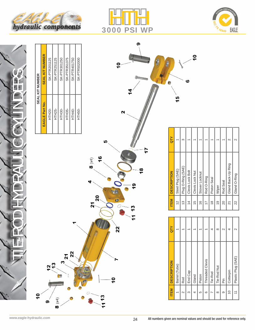
HTH TIE-ROD CYLINDER IS DOUBLE ACTING CYLINDER WITH:
ROD: Steel, induction hardened to 45-50 Rockwell C and chrome plated 0.001” thick for a final surface hardness 69-71 Rockwell C. ASTM B117-07a salt spray testing up to 96 hours
PISTON: Ductile Iron, for increased durability.
TUBE: Steel, Honed and precision finished for extended seal life STEEL TIE-ROD: High tensile strength to prevent stretching
END CAP : With 2 ORB ports at 90° toeach other for greater flexibility of assembly
ATTACHMENT: Ductile Iron, threaded female clevis,adjustable with locking bolt
PIN: Steel, zinc plated
SEALS: Top quality, North American Seals
PAINT: High quality paint for corrosion resistance up to 360 hours. (Standard color: Black)
RETRACTED / EXTRACTED
KL
H
N
RO
D
T
PORT
G
FI J
M
ØC
ØBØDØE
*Actual cylinder color is BLACK
*All dimensions are in inches
All product specifications are subject to change without prior notice.
24www.eagle-hydraulic.com
TIE-R
OD H
YDRA
ULIC
CYL
INDE
RSHTH
3000 PSI WPSE
AL
KIT
NU
MB
EREA
GLE
Par
t No.
SEA
L K
IT N
UM
BER
HTH
20-
SK-P
TR20
1125
HTH
25-
SK-P
TR25
1125
HTH
30-
SK-P
TR30
1250
HTH
35-
SK-P
TR35
1375
HTH
40-
SK-P
TR40
1750
HTH
50-
SK-P
TR50
2000
ITEM
DES
CR
IPTI
ON
QTY
1Ba
rrel (
Tube
)1
2R
od1
3En
d C
ap1
4G
land
1
5Pi
ston
1
6Th
read
ed C
levi
s1
7Ti
e-R
od4
8Ti
e-R
od N
ut8
9Pi
n2
10C
otte
rpin
4
11Pl
astic
Plu
g (S
AE)
2
ITEM
DES
CR
IPTI
ON
QTY
12St
eel P
lug
(SAE
)1
13Pl
ug O
-Rin
g (S
AE)
3
14C
levi
s Lo
ck B
olt
1
15C
levi
s Lo
ck N
ut1
16St
over
Loc
knut
1
17R
od O
-Rin
g1
18Pi
ston
Sea
l1
19W
iper
1
20R
od S
eal
1
21G
land
Bac
k-U
p R
ing
2
22G
land
O-R
ing
2
All numbers given are nominal values and should be used for reference only.

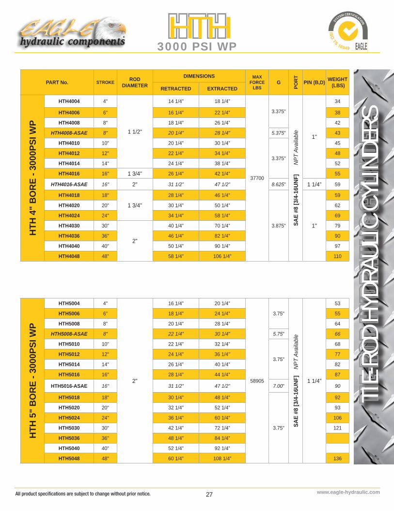
25 www.eagle-hydraulic.com
TIE-R
OD H
YDRA
ULIC
CYL
INDE
RS
HTH3000 PSI WP
PART No. STROKE RODDIAMETER
DIMENSIONS MAXFORCE
LBSG
PORT PIN (B,D) WEIGHT
(LBS)RETRACTED EXTRACTED
HTH
2" B
ORE
- 30
00PS
I WP
HTH2004 4"
1 1/8”
14 1/4” 18 1/4”
9425
3.375"
SAE
#8 [3
/4-1
6UNF
] N
PT A
vaila
ble
1"
17
HTH2006 6" 16 1/4” 22 1/4” 19
HTH2008 8" 18 1/4” 26 1/4” 20
HTH2008-ASAE 8" 20 1/4” 28 1/4” 5.375" 21
HTH2010 10" 20 1/4” 30 1/4”
3.375"
22
HTH2012 12" 22 1/4” 34 1/4” 23
HTH2014 14" 24 1/4” 38 1/4” 25
HTH2016 16" 26 1/4” 42 1/4” 26
HTH2018 18" 28 1/4” 46 1/4”
3.375"
28
HTH2020 20" 30 1/4” 50 1/4” 29
HTH2024 24" 34 1/4” 58 1/4” 32
HTH2030 30" 40 1/4” 70 1/4” 36
HTH2036 36" 46 1/4” 82 1/4” 41
HTH2040 40" 50 1/4” 90 1/4” 45
HTH2048 48" 58 1/4” 106 1/4” 51
HTH
2.5"
BO
RE -
3000
PSI W
P
HTH2504 4"
1 1/4”
14 1/4” 18 1/4”
14726
3.375"
SAE
#8 [3
/4-1
6UNF
] N
PT A
vaila
ble
1"
18
HTH2506 6" 16 1/4” 22 1/4” 21
HTH2508 8" 18 1/4” 26 1/4” 23
HTH2508-ASAE 8" 20 1/4” 28 1/4” 5.375" 24
HTH2510 10" 20 1/4” 30 1/4”
3.375"
25
HTH2512 12" 22 1/4” 34 1/4” 26
HTH2514 14" 24 1/4” 38 1/4” 28
HTH2516 16" 26 1/4” 42 1/4” 30
HTH2518 18" 28 1/4” 46 1/4”
3.375"
33
HTH2520 20" 30 1/4” 50 1/4” 34
HTH2524 24" 34 1/4” 58 1/4” 40
HTH2530 30" 40 1/4” 70 1/4” 43
HTH2536 36" 46 1/4” 82 1/4” 49
HTH2540 40" 50 1/4” 90 1/4” 54
HTH2548 48" 58 1/4” 106 1/4” 60
ITEM
DES
CR
IPTI
ON
QTY
1Ba
rrel (
Tube
)1
2R
od1
3En
d C
ap1
4G
land
1
5Pi
ston
1
6Th
read
ed C
levi
s1
7Ti
e-R
od4
8Ti
e-R
od N
ut8
9Pi
n2
10C
otte
rpin
4
11Pl
astic
Plu
g (S
AE)
2
All product specifications are subject to change without prior notice.

26www.eagle-hydraulic.com
TIE-R
OD H
YDRA
ULIC
CYL
INDE
RSHTH
3000 PSI WP
PART No. STROKE RODDIAMETER
DIMENSIONS MAXFORCE
LBSG
PORT PIN (B,D) WEIGHT
(LBS)RETRACTED EXTRACTED
HTH
3" B
ORE
- 30
00PS
I WP
HTH3004 4"
1 1/4”
14 1/4” 18 1/4”
21205
3.375"
SAE
#8 [3
/4-1
6UNF
] N
PT A
vaila
ble 1"
23
HTH3006 6" 16 1/4” 22 1/4” 26
HTH3008 8" 18 1/4” 26 1/4” 28
HTH3008-ASAE 8" 20 1/4” 28 1/4” 3.375" 29
HTH3010 10" 20 1/4” 30 1/4”
3.375"
30
HTH3012 12" 22 1/4” 34 1/4” 33
HTH3014 14" 24 1/4” 38 1/4” 35
HTH3016 16"
1 1/2”
26 1/4” 42 1/4” 38
HTH3016-ASAE 16" 31 1/2” 47 1/2” 8.625" 1 1/4” 40
HTH3018 18" 28 1/4” 46 1/4”
3.375" 1"
40
HTH3020 20" 30 1/4” 50 1/4” 42
HTH3024 24" 34 1/4” 58 1/4” 47
HTH3030 30" 40 1/4” 70 1/4” 54
HTH3036 36" 46 1/4” 82 1/4” 61
HTH3040 40" 50 1/4” 90 1/4” 66
HTH3048 48" 58 1/4” 106 1/4” 75
HTH
3.5"
BO
RE -
3000
PSI W
P
HTH3504 4"
1 1/4”
14 1/4” 18 1/4”
28863
3.50"SA
E #8
[3/4
-16U
NF]
NPT
Ava
ilabl
e
1"
27
HTH3506 6" 16 1/4” 22 1/4” 30
HTH3508 8" 18 1/4” 26 1/4” 33
HTH3508-ASAE 8" 20 1/4” 28 1/4” 5.50" 34
HTH3510 10" 20 1/4” 30 1/4”
3.50"
36
HTH3512 12" 22 1/4” 34 1/4” 38
HTH3514 14" 24 1/4” 38 1/4” 41
HTH3516 16"
1 1/2”
26 1/4” 42 1/4” 44
HTH3516-ASAE 16" 31 1/2” 47 1/2” 8.80" 1 1/4” 46
HTH3518 18" 28 1/4” 46 1/4”
3.50" 1"
47
HTH3520 20" 30 1/4” 50 1/4” 49
HTH3524 24" 34 1/4” 58 1/4” 55
HTH3530 30" 40 1/4” 70 1/4” 63
HTH3036 36" 46 1/4” 82 1/4” 72
HTH3040 40" 50 1/4” 90 1/4” 77
HTH3048 48" 58 1/4” 106 1/4” 88
All numbers given are nominal values and should be used for reference only.
27 www.eagle-hydraulic.com
TIE-R
OD H
YDRA
ULIC
CYL
INDE
RS
HTH3000 PSI WP
PART No. STROKE RODDIAMETER
DIMENSIONS MAXFORCE
LBSG
PORT PIN (B,D) WEIGHT
(LBS)RETRACTED EXTRACTED
HTH
4" B
ORE
- 30
00PS
I WP
HTH4004 4"
1 1/2”
14 1/4” 18 1/4”
37700
3.375"
SAE
#8 [3
/4-1
6UNF
]
NPT
Ava
ilabl
e
1"
34
HTH4006 6" 16 1/4” 22 1/4” 38
HTH4008 8" 18 1/4” 26 1/4” 42
HTH4008-ASAE 8" 20 1/4” 28 1/4” 5.375" 43
HTH4010 10" 20 1/4” 30 1/4”
3.375"
45
HTH4012 12" 22 1/4” 34 1/4” 48
HTH4014 14" 24 1/4” 38 1/4” 52
HTH4016 16" 1 3/4" 26 1/4” 42 1/4” 55
HTH4016-ASAE 16" 2" 31 1/2” 47 1/2” 8.625" 1 1/4” 59
HTH4018 18"
1 3/4"
28 1/4” 46 1/4”
3.875" 1"
59
HTH4020 20" 30 1/4” 50 1/4” 62
HTH4024 24" 34 1/4” 58 1/4” 69
HTH4030 30"
2"
40 1/4” 70 1/4” 79
HTH4036 36" 46 1/4” 82 1/4” 90
HTH4040 40" 50 1/4” 90 1/4” 97
HTH4048 48" 58 1/4” 106 1/4” 110
HTH
5" B
ORE
- 30
00PS
I WP
HTH5004 4"
2"
16 1/4” 20 1/4”
58905
3.75"
SAE
#8 [3
/4-1
6UNF
] N
PT A
vaila
ble
1 1/4”
53
HTH5006 6" 18 1/4” 24 1/4” 55
HTH5008 8" 20 1/4” 28 1/4” 64
HTH5008-ASAE 8" 22 1/4” 30 1/4” 5.75" 66
HTH5010 10" 22 1/4” 32 1/4”
3.75"
68
HTH5012 12" 24 1/4” 36 1/4’’ 77
HTH5014 14" 26 1/4” 40 1/4” 82
HTH5016 16" 28 1/4” 44 1/4” 87
HTH5016-ASAE 16" 31 1/2” 47 1/2” 7.00" 90
HTH5018 18" 30 1/4” 48 1/4”
3.75"
92
HTH5020 20" 32 1/4” 52 1/4” 93
HTH5024 24" 36 1/4” 60 1/4” 106
HTH5030 30" 42 1/4” 72 1/4” 121
HTH5036 36" 48 1/4” 84 1/4”
HTH5040 40" 52 1/4” 92 1/4”
HTH5048 48" 60 1/4” 108 1/4” 136
All product specifications are subject to change without prior notice.
28www.eagle-hydraulic.com
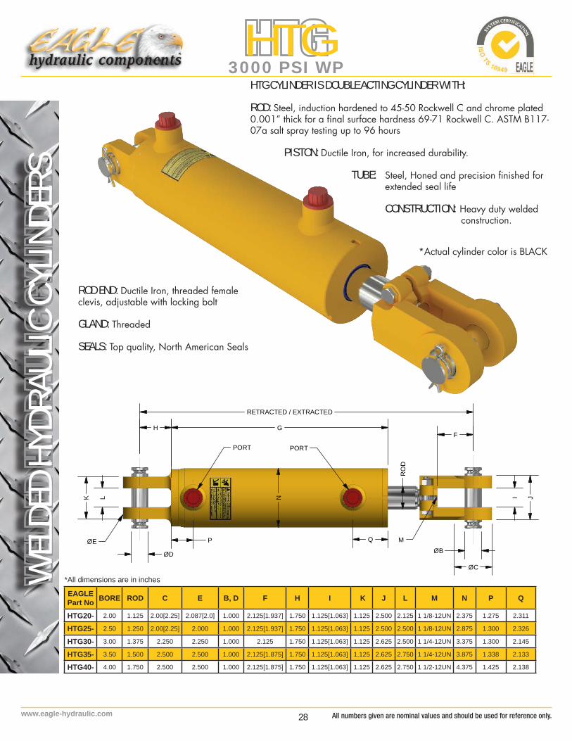
WEL
DED
HYDR
AULIC
CYL
INDE
RSHTG
3000 PSI WP
EAGLE Part No BORE ROD C E B, D F H I K J L M N P Q
HTG20- 2.00 1.125 2.00[2.25] 2.087[2.0] 1.000 2.125[1.937] 1.750 1.125[1.063] 1.125 2.500 2.125 1 1/8-12UN 2.375 1.275 2.311
HTG25- 2.50 1.250 2.00[2.25] 2.000 1.000 2.125[1.937] 1.750 1.125[1.063] 1.125 2.500 2.500 1 1/8-12UN 2.875 1.300 2.326
HTG30- 3.00 1.375 2.250 2.250 1.000 2.125 1.750 1.125[1.063] 1.125 2.625 2.500 1 1/4-12UN 3.375 1.300 2.145
HTG35- 3.50 1.500 2.500 2.500 1.000 2.125[1.875] 1.750 1.125[1.063] 1.125 2.625 2.750 1 1/4-12UN 3.875 1.338 2.133
HTG40- 4.00 1.750 2.500 2.500 1.000 2.125[1.875] 1.750 1.125[1.063] 1.125 2.625 2.750 1 1/2-12UN 4.375 1.425 2.138
HTG CYLINDER IS DOUBLE ACTING CYLINDER WITH:
ROD: Steel, induction hardened to 45-50 Rockwell C and chrome plated 0.001” thick for a final surface hardness 69-71 Rockwell C. ASTM B117-07a salt spray testing up to 96 hours
PISTON: Ductile Iron, for increased durability.
TUBE: Steel, Honed and precision finished for extended seal life CONSTRUCTION: Heavy duty welded construction.
ROD END: Ductile Iron, threaded femaleclevis, adjustable with locking bolt
GLAND: Threaded
SEALS: Top quality, North American Seals
RETRACTED / EXTRACTED
H
K L N
PORT PORT
F
JI
MØB
ØC
RO
D
ØD
ØE
G
P Q
*Actual cylinder color is BLACK
*All dimensions are in inches
All numbers given are nominal values and should be used for reference only.
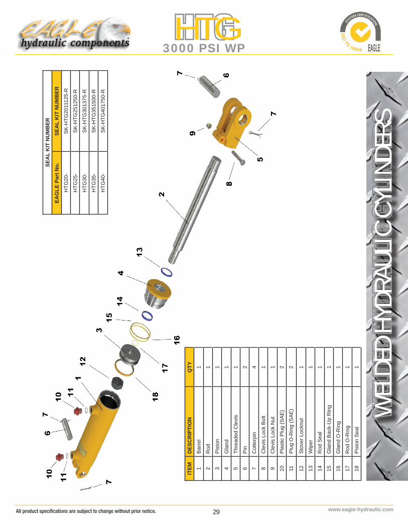
29 www.eagle-hydraulic.com
WEL
DED
HYDR
AULIC
CYL
INDE
RS
HTG3000 PSI WP
SEA
L K
IT N
UM
BER
EAG
LE P
art N
o.SE
AL
KIT
NU
MB
ERH
TG20
-SK
-HTG
2011
125-
R
HTG
25-
SK-H
TG25
1250
-R
HTG
30-
SK-H
TG30
1375
-R
HTG
35-
SK-H
TG35
1500
-R
HTG
40-
SK-H
TG40
1750
-R
ITEM
DES
CR
IPTI
ON
QTY
1Ba
rrel
1
2R
od1
3Pi
ston
1
4G
land
1
5Th
read
ed C
levi
s1
6Pi
n2
7C
otte
rpin
4
8C
levi
s Lo
ck B
olt
1
9C
levi
s Lo
ck N
ut1
10Pl
astic
Plu
g (S
AE)
2
11Pl
ug O
-Rin
g (S
AE)
2
12St
over
Loc
knut
1
13W
iper
1
14R
od S
eal
1
15G
land
Bac
k-U
p R
ing
1
16G
land
O-R
ing
1
17R
od O
-Rin
g1
18Pi
ston
Sea
l1
All product specifications are subject to change without prior notice.

30www.eagle-hydraulic.com
WEL
DED
HYDR
AULIC
CYL
INDE
RSHTG
3000 PSI WP
PART No. STROKE ROD DIAMETER
DIMENSIONSG
MAXFORCE
LBS PORT PIN (B,D) WEIGHT
(LBS)RETRACTED EXTRACTED
HTG
2" B
ORE
3
000P
SI W
P
HTG2004 4"
1 1/8”
14 1/4” 18 1/4” 8.92”
9425
SAE
#6
1/2
NPT
Ava
ilabl
e
1"
16
HTG2006 6" 16 1/4” 22 1/4” 10.92” 17
HTG2008 8" 18 1/4” 26 1/4” 12.92” 18
HTG2008-ASAE 8" 20 1/4” 28 1/4” 12.92” 19
HTG2010 10" 20 1/4” 30 1/4” 14.92” 20
HTG2012 12" 22 1/4” 34 1/4” 16.92” 22
HTG2014 14" 24 1/4” 38 1/4” 18.92” 23
HTG2016 16" 26 1/4” 42 1/4” 20.92” 25
HTG2018 18" 28 1/4” 46 1/4” 22.92” 26
HTG2020 20" 30 1/4” 50 1/4” 24.92” 28
HTG2024 24" 34 1/4” 58 1/4” 28.92” 31
HTG2028 28" 38 1/4” 66 1/4” 32.92” 37
HTG2030 30" 40 1/4” 70 1/4” 34.92” 39
HTG2032 32" 42 1/4” 74 1/4” 36.92” 41
HTG2034 34" 44 1/4” 78 1/4” 38.92” 43
HTG2036 36" 46 1/4” 82 1/4” 40.92” 45
HTG
2.5
" BO
RE
3000
PSI W
P
HTG2504 4"
1 1/4”
14 1/4” 18 1/4” 9”
14726
SAE
#8
1/2
NPT
Ava
ilabl
e
1"
17
HTG2506 6" 16 1/4” 22 1/4” 11” 18
HTG2508 8" 18 1/4” 26 1/4” 13” 20
HTG2508-ASAE 8" 20 1/4” 28 1/4” 13” 21
HTG2510 10" 20 1/4” 30 1/4” 15” 22
HTG2512 12" 22 1/4” 34 1/4” 17” 23
HTG2514 14" 24 1/4” 38 1/4” 19” 25
HTG2516 16" 26 1/4” 42 1/4” 21” 27
HTG2518 18" 28 1/4” 46 1/4” 23” 29
HTG2520 20" 30 1/4” 50 1/4” 25” 31
HTG2524 24" 34 1/4” 58 1/4” 29” 35
HTG2528 28" 38 1/4” 66 1/4” 33” 37
HTG2530 30" 40 1/4” 70 1/4” 35” 41
HTG2532 32" 42 1/4” 74 1/4” 37” 43
HTG2534 34" 44 1/4” 78 1/4” 39” 45
HTG2536 36" 46 1/4” 82 1/4” 41” 47
All numbers given are nominal values and should be used for reference only.

31 www.eagle-hydraulic.com
WEL
DED
HYDR
AULIC
CYL
INDE
RS
HTG3000 PSI WP
PART No. STROKE ROD DIAMETER
DIMENSIONSG
MAXFORCE
LBS PORT PIN (B,D) WEIGHT
(LBS)RETRACTED EXTRACTED
HTG
3" B
ORE
3000
PSI W
P
HTG3004 4"
1 3/8”
14 1/4” 18 1/4” 8.895”
21205
SAE
#8
1/2
NPT
Ava
ilabl
e
1"
18
HTG3006 6" 16 1/4” 22 1/4” 10.895” 20
HTG3008 8" 18 1/4” 26 1/4” 12.895” 22
HTG3008-ASAE 8" 20 1/4” 28 1/4” 12.895” 23
HTG3010 10" 20 1/4” 30 1/4” 14.895” 26
HTG3012 12" 22 1/4” 34 1/4” 16.895” 28
HTG3014 14" 24 1/4” 38 1/4” 18.895” 31
HTG3016 16" 26 1/4” 42 1/4” 20.895” 33
HTG3018 18" 28 1/4” 46 1/4” 22.895” 35
HTG3020 20" 30 1/4” 50 1/4” 24.895” 39
HTG3024 24" 34 1/4” 58 1/4” 28.895” 43
HTG3028 28" 38 1/4” 66 1/4” 32.895” 46
HTG3030 30" 40 1/4” 70 1/4” 34.895” 49
HTG3032 32" 42 1/4” 74 1/4” 36.895” 50
HTG3034 34" 44 1/4” 78 1/4” 38.895” 53
HTG3036 36" 46 1/4” 82 1/4” 40.895” 54
HTG
3.5
" BO
RE
3000
PSI W
P
HTG3504 4"
1 1/2”
14 1/4” 18 1/4” 8.92”
28863
SAE
#8
1/2
NPT
Ava
ilabl
e
1"
25
HTG3506 6" 16 1/4” 22 1/4” 10.92” 27
HTG3508 8" 18 1/4” 26 1/4” 12.92” 28
HTG3508-ASAE 8" 20 1/4” 28 1/4” 12.92” 29
HTG3510 10" 20 1/4” 30 1/4” 14.92” 31
HTG3512 12" 22 1/4” 34 1/4” 16.92” 33
HTG3514 14" 24 1/4” 38 1/4” 18.92” 35
HTG3516 16" 26 1/4” 42 1/4” 20.92” 36
HTG3518 18" 28 1/4” 46 1/4” 22.92” 38
HTG3520 20" 30 1/4” 50 1/4” 24.92” 43
HTG3524 24" 34 1/4” 58 1/4” 28.92” 48
HTG3528 28" 38 1/4” 66 1/4” 32.92” 52
HTG3530 30" 40 1/4” 70 1/4” 34.92” 54
HTG3532 32" 42 1/4” 74 1/4” 36.92” 56
HTG3534 34" 44 1/4” 78 1/4” 38.92” 58
HTG3536 36" 46 1/4” 82 1/4” 40.92” 60
All product specifications are subject to change without prior notice.

32www.eagle-hydraulic.com
WEL
DED
HYDR
AULIC
CYL
INDE
RSHTG
3000 PSI WP
PART No. STROKE ROD DIAMETER
DIMENSIONSG
MAXFORCE
LBS PORT PIN (B,D) WEIGHT
(LBS)RETRACTED EXTRACTED
HTG
4" B
ORE
3000
PSI W
P
HTG4004 4"
1 3/4”
14 1/4” 18 1/4” 8.95”
37700
SAE
#8
1/2
NPT
Ava
ilabl
e
1"
35
HTG4006 6" 16 1/4” 22 1/4” 10.95” 37
HTG4008 8" 18 1/4” 26 1/4” 12.95” 38
HTG4008-ASAE 8" 20 1/4” 28 1/4” 12.95” 40
HTG4010 10" 20 1/4” 30 1/4” 14.95” 43
HTG4012 12" 22 1/4” 34 1/4” 16.95” 45
HTG4014 14" 24 1/4” 38 1/4” 18.95” 48
HTG4016 16" 26 1/4” 42 1/4” 20.95” 54
HTG4018 18" 28 1/4” 46 1/4” 22.95” 56
HTG4020 20" 30 1/4” 50 1/4” 24.95” 58
HTG4024 24" 34 1/4” 58 1/4” 28.95” 60
HTG4028 28" 38 1/4” 66 1/4” 32.95” 63
HTG4030 30" 40 1/4” 70 1/4” 34.95” 65
HTG4032 32" 42 1/4” 74 1/4” 36.95” 68
HTG4034 34" 44 1/4” 78 1/4” 38.95” 72
HTG4036 36" 46 1/4” 82 1/4” 40.95” 74
Top Quality North American Seals
NITRIDED HYDRAULIC CYLINDER RODSLiquid Nitriding is a surface treatment process that produces a black in color finish that is very hard and corrosion resistant. It combines a high surface hardness with increased corrosion resistance. The process begins with the cleaning and polishing of the material to a surface roughness of 16 Ra or better. The steel bars or components are then fixed vertically, and submerged into an electrically controlled liquid tank.
Forged Hydraulic Cylinder ComponentForgings are superior over castings and fabrications as the structural integrity can withstand the higher forces that exist in a rigorous or high duty cycle application.
All numbers given are nominal values and should be used for reference only.

33 www.eagle-hydraulic.com
SNOW
PLOW
HYD
RAUL
IC C
YLIN
DERS
HSP2500 PSI WP
HSP CYLINDER IS SINGLE ACTING CYLINDER WITH:
APPLICATION: High Shock Applications
CONSTRUCTION: Welded Construction
GLAND: Threaded, Ductile Iron SEALS: Top quality, North American Seals
CUSTOM AND DOUBLE ACTING CYLINDERSAvailable on request
NITRIDE RODAvailable on request
MODEL NUMBER A SP - 175 - 12 - 0750 - 00
Suffix for Model Type Cylinder Bore (ex:175=1.75”)
Cylinder Stroke (ex: 12=12”)
Design codePin Diameter (ex: 0625=0.625”)Replacement
A - Artic F - Fisher M - Meyer W - Western
All pictures may differ from the final products. Product specifications are subject to changes without notice.
*Actual cylinder color is BLACK
All product specifications are subject to change without prior notice.
34www.eagle-hydraulic.com
SNOW
PLOW
HYD
RAUL
IC C
YLIN
DERS
HSP2500 PSI WP
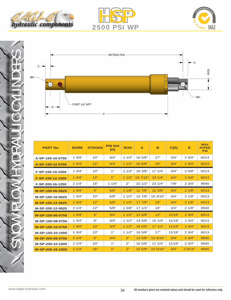
PART No. BORE STROKE PIN DIA (H) ROD A B C(D) E
MAXRATED
PSI
A-SP-150-10-0750 1 3/4” 10'' 3/4” 1 1/2” 16 5/8” 17" 3/4” 2 3/4” 6013
A-SP-150-12-0750 1 3/4” 12'' 3/4” 1 1/2” 16 5/8” 19" 3/4” 2 3/4” 6013
F-SP-150-10-1000 1 3/4” 10'' 1" 1 1/2” 16 3/8” 17 1/4” 3/4” 2 5/8” 6013
F-SP-150-12-1000 1 3/4” 12'' 1" 1 1/2” 18 7/16” 19 1/4” 3/4” 2 5/8” 6013
F-SP-200-16-1250 2 1/4” 16'' 1 1/4” 2" 22 1/2” 23 1/4” 7/8” 2 3/4” 9940
M-SP-150-06-0625 1 3/4” 6'' 5/8” 1 1/8” 11 7/8” 12 3/8” 3/4” 2 1/8” 6013
M-SP-150-10-0625 1 3/4” 10'' 5/8” 1 1/2” 15 7/8” 16 3/16” 3/4” 2 1/8” 6013
M-SP-150-12-0625 1 3/4” 12'' 5/8” 1 1/2” 17 7/8” 18" 3/4” 2 1/8” 6013
M-SP-200-12-0625 2 1/4” 12'' 5/8” 1 5/8” 17 1/4” 18" 3/4” 2 1/8” 9940
W-SP-150-06-0750 1 3/4” 6'' 3/4” 1 1/2” 12 5/8” 13" 11/16” 2 3/4” 6013
W-SP-150-08-0750 1 3/4” 8'' 3/4” 1 1/2” 14 5/8” 15 1/4” 11/16" 2 3/4” 6013
W-SP-150-10-0750 1 3/4” 10'' 3/4” 1 1/2” 16 5/8” 17 1/4” 11/16" 2 3/4” 6013
W-SP-150-10-1000 1 3/4” 10'' 1" 1 1/2” 16 5/8” 17" 11/16" 2 3/4” 6013
W-SP-200-06-0750 2 1/4” 6'' 3/4” 2" 12 5/8” 13 3/16” 3/4” 2 3/4” 9940
W-SP-200-10-1000 2 1/4” 10'' 1" 2" 16 5/8” 17 1/4” 11/16" 2 3/4” 9940
W-SP-200-16-1000 2 1/4” 16'' 1" 2" 22 5/8” 23 5/16” 3/4” 2 9/16" 9940
RETRACTED
A
EPORT 1/4" NPT
C
ØH
ØH
RO
D
D
All numbers given are nominal values and should be used for reference only.

35 www.eagle-hydraulic.com
SNOW
PLOW
HYD
RAUL
IC C
YLIN
DERS
HSP2500 PSI WP
SEA
L K
IT N
UM
BER
EAG
LE P
art N
o.SE
AL
KIT
NU
MB
ERA-
SP-1
50-1
0-07
50SK
-SP1
50
A-SP
-150
-12-
0750
SK-S
P150
F-SP
-150
-10-
1000
SK-S
P150
F-SP
-150
-12-
1000
SK-S
P150
F-SP
-200
-16-
1250
SK-S
P200
M-S
P-15
0-06
-062
5SK
-SP1
50
M-S
P-15
0-10
-062
5SK
-SP1
50
M-S
P-15
0-12
-062
5SK
-SP1
50
M-S
P-20
0-12
-062
5SK
-SP2
00
W-S
P-15
0-06
-075
0SK
-SP1
50
W-S
P-15
0-08
-075
0SK
-SP1
50
W-S
P-15
0-10
-075
0SK
-SP1
50
W-S
P-15
0-10
-100
0SK
-SP1
50
W-S
P-20
0-06
-075
0SK
-SP2
00
W-S
P-20
0-10
-100
0SK
-SP2
00
W-S
P-20
0-16
-100
0SK
-SP2
00
ITEM
DES
CR
IPTI
ON
QTY
1Ba
rrel
1
2R
od1
3G
land
1
4Pi
ston
Rin
g2
5G
land
Sea
ls4
6W
iper
1
7Pl
astic
Plu
g N
PT1
All product specifications are subject to change without prior notice.

36www.eagle-hydraulic.com
TELE
SCOP
IC H
YDRA
ULIC
CYL
INDE
RSHTC
3000 PSI WP
7 TONS INVERSE
PART No. STROKE A B C D E F G H L PORT WEIGHT[Lbs]
VOLUME[Gal.]
HTC-07833 78" 35.5" 3.75" 2" 1.063" 3.0" 1.25" 6.5" 1.25" 7"SAE #8
(3/4-16UNF)
68 1.6
HTC-09033 90" 39.5" 3.75" 2" 1.063" 3.0" 1.25" 6.5" 1.25" 7" 75 1.8
HTC-10833 108" 45" 3.75" 2" 1.063" 3.0" 1.25" 6.5" 1.25" 7" 101 2.2
12 TONS INVERSEHTC-07843 78” 34.75” 4.4” 2” 1.063” 3.0” 1.5” 7.5” 1.5” 7”
SAE #8(3/4-16UNF)
106 2.5
HTC-09043 90” 38.75” 4.4” 2” 1.063” 3.0” 1.5” 7.5” 1.5” 7” 107 2.8
HTC-10843 108” 44.75” 4.4” 2” 1.063” 3.0” 1.5” 7.5” 1.5” 7” 132 3.4
HTC-12043 120” 48.75” 4.4” 2” 1.063” 3.0” 1.5” 7.5” 1.5” 7” 143 3.8
HTC-14443 144” 56.78” 4.4” 2” 1.063” 2.25” 1.5” 7.5” 1.5” 7” 166 4.6
HTC- Telescopic Cylinder for 7 tons and 12 tons inverse.
All pictures may differ from the final products. Product specifications are subject to changes without notice.
A (RETRACTED)
B
ØC
E
PORT
ØD
G
ØF
HH
L
*Actual cylinder color is BLACK
All numbers given are nominal values and should be used for reference only.

37 www.eagle-hydraulic.com
TELE
SCOP
IC H
YDRA
ULIC
CYL
INDE
RS
HTC3000 PSI WP
SEA
L K
IT N
UM
BER
EAG
LE P
art N
o.SE
AL
KIT
NU
MB
ERH
TC-0
7833
SK-T
EL-4
5-60
-75
HTC
-090
33SK
-TEL
-45-
60-7
5
HTC
-108
33SK
-TEL
-45-
60-7
5
HTC
-078
43SK
-TEL
-60-
75-9
2
HTC
-090
43SK
-TEL
-60-
75-9
2
HTC
-108
43SK
-TEL
-60-
75-9
2
HTC
1204
3SK
-TEL
-60-
75-9
2
HTC
-144
43SK
-TEL
-60-
75-9
2
ITEM
DES
CR
IPTI
ON
QTY
1Ba
rrel
1
2Tu
be #
31
3Tu
be #
21
4Tu
be #
11
5En
d C
ap1
6R
od E
nd1
7D
rain
Plu
g1
8En
d C
ap O
-Rin
g1
9Ba
rrel S
nap
Rin
g1
10Ba
rrel R
od S
eal
1
11Ba
rrel W
ear B
and
1
12Ba
rrel W
iper
1
13Tu
be #
2 Sn
ap R
ing
6
14Tu
be #
3 Sn
ap R
ing
4
15#3
Pis
ton
Seal
2
16Tu
be #
3Rod
Sea
l1
17Tu
be #
3 W
ear B
and
1
ITEM
DES
CR
IPTI
ON
QTY
18Tu
be #
3 W
iper
1
19Tu
be #
1 Sn
ap R
ing
6
20#2
Pis
ton
Seal
2
21G
reas
e Fi
tting
1/8
-27
NPT
2
22Tu
be #
2 R
od S
eal
1
23Tu
be #
2 W
ear B
and
1
24Tu
be #
2 W
iper
1
25#1
Pis
ton
Seal
2
26R
od O
-Rin
g1
27Pl
astic
Plu
g (S
AE)
1
28Pl
ug O
-Rin
g (S
AE)
1 7 TONS INVERSE
PART No. STROKE A B C D E F G H L PORT WEIGHT[Lbs]
VOLUME[Gal.]
HTC-07833 78" 35.5" 3.75" 2" 1.063" 3.0" 1.25" 6.5" 1.25" 7"SAE #8
(3/4-16UNF)
68 1.6
HTC-09033 90" 39.5" 3.75" 2" 1.063" 3.0" 1.25" 6.5" 1.25" 7" 75 1.8
HTC-10833 108" 45" 3.75" 2" 1.063" 3.0" 1.25" 6.5" 1.25" 7" 101 2.2
12 TONS INVERSEHTC-07843 78” 34.75” 4.4” 2” 1.063” 3.0” 1.5” 7.5” 1.5” 7”
SAE #8(3/4-16UNF)
106 2.5
HTC-09043 90” 38.75” 4.4” 2” 1.063” 3.0” 1.5” 7.5” 1.5” 7” 107 2.8
HTC-10843 108” 44.75” 4.4” 2” 1.063” 3.0” 1.5” 7.5” 1.5” 7” 132 3.4
HTC-12043 120” 48.75” 4.4” 2” 1.063” 3.0” 1.5” 7.5” 1.5” 7” 143 3.8
HTC-14443 144” 56.78” 4.4” 2” 1.063” 2.25” 1.5” 7.5” 1.5” 7” 166 4.6
All product specifications are subject to change without prior notice.

38www.eagle-hydraulic.com
TELE
SCOP
IC H
YDRA
ULIC
CYL
INDE
RSHTC
3000 PSI WPORDER INFORMATION
HTC - 078 33 - ORB - 00
STROKE
CAPACITY33 - for 7 tons43 - for 12 tons
PORT omit - 1/2 NPT ORB - SAE#8-3/4-16UNF
Design codeFactory Specification
MODEL
ACCESSORIES FOR TELESCOPIC CYLINDERSMOUNTING BRACKETS
for 7 and 12 tons
for 7 tonsHTCS07-A
for 12 tonsHTCS12-A
SUPPORT FRAME
HTC SB07-A
All numbers given are nominal values and should be used for reference only.

39 www.eagle-hydraulic.com
ORDER INFORMATION(if different than our Standard)
All pictures may differ from the final products. Product specifications are subject to changes without notice.
All product specifications are subject to change without prior notice.

40www.eagle-hydraulic.com All numbers given are nominal values and should be used for reference only.

41 www.eagle-hydraulic.com
NON-TRANSFERABLE LIMITED WARRANTY
All product specifications are subject to change without prior notice.
This document outlines the warranty associated with Eagle Hydraulic Components’ products. If you have any questions regarding this warranty, please contact our service department by phone at 1-877-382-2850 or by e-mail at [email protected].
Eagle Hydraulic Components, Inc., formerly HWF Hydraulique International Inc. (“EAGLE”), warrants to you, the original purchaser, that all of its products are free from defects in material or workmanship under normal use and service for the following periods:
EAGLE’s warranty is limited to the Original Equipment Manufacturer (“OEM”) and/or distributor to whom EAGLE’s products are originally sold. EAGLE’s warranty is non-transferable to any subsequent purchaser and limited to original purchaser from EAGLE.
EAGLE’s 2 year warranty period is calculated from the date of manufacture, which is engraved on the body of every cylinder.
MAINTENANCE: Inspections and maintenance should be performed on all EAGLE products at regular intervals. While necessary maintenance or repairs on your EAGLE product can be performed by any company, we recommend that you use only authorized EAGLE dealers.
WARNING: IMPROPER OR INCORRECTLY PERFORMED MAINTENANCE OR REPAIR VOIDS THIS WARRANTY.
How to Obtain Service From EAGLE Under This Limited Warranty:To obtain service under this warranty, contact our service department by phone at 1-877-382-2850 or by e-mail at [email protected].
Please note, EAGLE’s obligation to repair or replace your EAGLE product is subject to confirmation by EAGLE’s service technicians that the part contains a defect in material or workmanship.
EAGLE’s obligations under this warranty are limited to the repair or replacement of the subject EAGLE part or product. The decision to repair or replace any defective EAGLE part or product is solely at the discretion of EAGLE. Please further note, EAGLE reserves the right to direct any and all repairs performed under this warranty to a local approved service location.
What This Warranty Does Not Cover:EAGLE shall have no responsibility for the following:
• Troubleshooting, diagnostic, removal, or reinstallation labor charges of any EAGLE part or product unless prior written approval is obtained from EAGLE;• Freight charges for either defective parts, new parts, or repaired; ***• Claims for loss of time, inconvenience, loss of use, profits or any other incidental or consequential damages arising from any product defect;• Conditions arising from or caused by alteration of the product, product misuse or neglect, lack of proper maintenance, fire, theft, loss, or damage to the
product (including, but not limited to, intentional damage, weather related damage, or any other type of physical damage);• Corrosion, unless the material is found to be out of specification;• Failure caused by foreign contamination introduced to the cylinder;• Paint, unless out of specification;• Normal wear of internal components.
*** Please note, in certain circumstances, EAGLE may decide to reimburse a customer for freight charges associated with a warranty claim. However, the decision to provide reimbursement for freight changes remains within the sole discretion of EAGLE.
Products which experience color change due to normal weathering are also excluded from this warranty (including non-uniform fading and color changes resulting from unequal exposure of panels to the sun and elements). For purposes this warranty, the term “normal weathering” means exposure to ultraviolet (sun) light, and extremes of temperature and atmosphere which will cause any colored or painted surface to fade, darken, chalk, crack, or acquire surface accumulation of dirt or stains. The severity of these conditions depends on air quality, the geographic location of the property at which the products are installed, and other local conditions over which EAGLE has no control.
EAGLE shall not be liable for and this warranty does not apply or extend to any failure, defects, or damages arising from or connected with, without limitation, misuse, abuse, neglect, faulty or improper installation.
Warranty Void – Use Authorized Representative for Inspections:This warranty is null & void should the product be dismantled, opened, or serviced by anyone other than an approved representative of EAGLE. If you believe that your EAGLE product suffers from a defect covered by this warranty, contact our service department to report the problem and obtain information regarding where to bring your product for inspection.

42www.eagle-hydraulic.com All numbers given are nominal values and should be used for reference only.
Warranty procedure:
In order to validate each claim and administer our warranty, EAGLE requires each customer who is making a warranty claim to fill out a “Warranty Claim Form.” This form includes basic information, such as the Part Number, the Date Code, and a simple description of how the product failed. If possible, please describe the defect. EAGLE also requests that you provide a photograph of the product and any potentially defective conditions, to assist us in confirming your warranty claim.
Below please find a checklist of items to provide EAGLE to assist us process your warranty claim:
1. Warranty Claim Form 2. Part Number & Date Code 3. Invoice Number and Date 4. Photo that best portrays the defect
FAILURE TO SUBMIT A COMPLETED “WARRANTY CLAIM FORM” MAY RESULT IN THE DENIAL OF YOUR WARRANTY CLAIM.
If requested for inspection by EAGLE, defective parts must be shipped to EAGLE’s chosen shipping address. When returning a product, we recommend that you utilize an insured method of delivery, which includes a signature for acceptance of delivery.
Warranty Processing:
Through EAGLE’s Authorized Dealer: Upon arrival of your EAGLE product and Warranty Claim Form to EAGLE’s authorized dealer, EAGLE and the dealer will assess and investigate your warranty claim within five (5) working days to provide a preliminary assessment of any claims. If, based on this preliminary assessment, EAGLE believes that the product may contain a defect which falls within this warranty, EAGLE’s authorized dealer will make arrangements to return the product to EAGLE’s service headquarters in Montreal, Canada for final assessment. At that time, EAGLE will assign an RGA number (return goods authorization) to track the product. Please allow 2-3 weeks for assessment by EAGLE’s service headquarters.
Through EAGLE’s Headquarters: You may ship your EAGLE product and Warranty Claim Form directly to EAGLE’s service headquarters in Montreal, Canada to expedite processing of your claim.
If your EAGLE product contains a condition which falls within EAGLE’s warranty:
1. EAGLE will process the claim within 15-days after the product arrives in Montreal, Canada.2. EAGLE will either repair or replace the defective product, at our discretion..
NOTICE TO OEM DEALERS AND DISTRIBUTORS:With respect to warranty claims presented by EAGLE’s product dealers and distributors, EAGLE will consolidate all valid warranty claims, review them, and take action on a quarterly basis.
WARRANTY LIMITATIONS
THIS WARRANTY IS NOT APPLICABLE OUTSIDE OF NORTH AMERICA.
EAGLE reserves the right to discontinue or change any of its products, including colors, without providing notice to its dealers, distributors, or purchasers. Should a product covered by this warranty become unavailable for any reason, EAGLE reserves the right, at EAGLE’s sole discretion, to substitute a product that is of equal quality or refund the purchase price.
If the product is not returned to EAGLE’s headquarters for inspection, you the customer, must maintain and preserve the product as evidence. If EAGLE does not request the defective product to be returned, the customer may discard the product appropriately after 60 days.
THE WARRANTY PROVIDED ABOVE CONTAINS THE EXTENT OF ALL EXPRESS WARRANTIES. EAGLE MAKES NO WARRANTIES REGARDING ANY PRODUCT’S FITNESS FOR ANY PARTICULAR PURPOSE. EAGLE’S WARRANTY DOES NOT COVER ANY PROPERTY DAMAGE, PERSONAL INJURY, INCIDENTAL DAMAGE OR CONSEQUENTAL DAMAGE ALLEGEDLY ASSOCIATED WITH ITS PRODUCTS. EAGLE shall not be liable for inconvenience, labor, loss of time, maintenance, removal or reinstallation of the products or other incidental, special or consequential damages arising in relation to the purchase or use of the product.
BY PURCHASE OF EAGLE’S PRODUCT(S), INCLUDING THIS WARRANTY, BUYER ACCEPTS THIS WARRANTY IN LIEU OF ALL OTHER WARRANTIES, LIABILITIES OR OBLIGATIONS OF EAGLE, EITHER EXPRESSED OR IMPLIED, EXCEPT THAT THE DURATION OF ANY IMPLIED WARRANTY OF MERCHANTABILITY IS LIMITED IN TIME TO THE DURATION OF THIS WARRANTY. EAGLE SHALL IN NO EVENT BE LIABLE FOR CONSEQUENTIAL OR INCIDENTAL OR SPECIAL DAMAGES OF ANY KIND FOR BREACH OF ANY EXPRESS WRITTEN OR ORAL OR IMPLIED WARRANTY ON PRODUCTS. YOUR EXCLUSIVE REMEDY SHALL BE ENFORCEMENT OF THIS WARRANTY UPON THE TERMS AND CONDITIONS STATED HEREIN. NO REPRESENTATIVE OF EAGLE OR ITS DISTRIBUTORS OR DEALERS IS AUTHORIZED TO MAKE ANY CHANGE OR MODIFICATION TO THIS WARRANTY.
Some jurisdictions do not allow various limitations on implied warranties. Some jurisdictions do not allow the exclusion or limitation on consequential or special damage. As such, the limitations contained herein are subject to the limits of the applicable law. This warranty gives you specific legal rights, and you may also have other rights, all of which vary from jurisdiction to jurisdiction. If any provision of this warranty is declared to be illegal, unenforceable, or void, the remainder of this warranty shall be enforced to the extent permitted by law and the illegal, unenforceable or void provision shall be replaced with a mutually acceptable provision which comes closest to the intention of the underlying original provision, to the extent possible.

43 www.eagle-hydraulic.com All product specifications are subject to change without prior notice.
Defect Description Form – Hydraulic Cylinder
In order to assist us in validating your warranty claim, please provide as much detail possible to best describe the defect. This information is critical to help us understand the problem and take corrective measures in future initiatives.
Cylinder Part Number: _____________
Serial Number: _____________
Date Code: _____________
Description:_______________________________________________________________________________________________________________________________________________________
Location of Defect: Check applicable box
Weld Leak – Front Port Welded Zone – Rod End
– Rear Port – Base End
– End Cap Seals – Leaking from Head
– Feed Return Pipe – Leaking from Rod
– Internal Bypass
RGA #________________________
AUTH BY: _____________________ This area is for internal use only
DATE: ________________________
COMMENTS:____________________________________________________________________________________________
Company Name: ___________
Contact: _________________
Email: __________________
THIS WARRANTY IS EXPRESSLY IN LIEU OF ANY OTHER WARRANTIES, EXPRESSED OR IMPLIED, INCLUDING ANY IMPLIED WARRANT OF MERCHANTABILITY OR FITNESS FOR A PARTICULAR PURPOSE, AND OF ANY NON-CONTRACTUAL LIABILITIES INCLUDING LIABILITIES FOR PERSONAL INJURY OR PROPERTY DAMAGE OR ANY OTHER PRODUCT LIABILITIES BASED UPON NEGLIGENCE OR STRICT LIABILITY. ANY ADDITIONAL OR DIFFERENT LIABILITIES ASSUMED BY EAGLE MUST BE CONTAINED IN WRITING AND SIGNED BY AN AUTHORIZED EMPLOYEE OF EAGLE. EAGLE HAS THE RIGHT TO REVIEW AND CANCEL, CHANGE OR MODIFY THIS AGREEMENT. IN THE CASE OF DISCREPANCY, THE EAGLE WARRANTY POLICY SHALL PREVAIL. FAILURE TO SUBMIT A COMPLETED “DEFECT DESCRIPTION FORM” AS PER THIS DOCUMENT WILL RENDER THE WARRANTY CLAIM AS DENIED. SPECIAL NOTE; BENT, BROKEN, DAMAGED RODS, SYSTEM CONTAMINATION, UNAUTHORIZED WELDING, DISASSEMBLY, REPAIR, MISUSE, ABUSE, ACCIDENTAL OR IMPROPER INSTALLATION OF THE INTENDED APPLICATION WILL VOID ALL WARRANTY.

“A Canadian Owned & Operated Company”