Table of Contents Mechanical - hubbellcdn
62
Mechanical 1-800-465-7051 (Canada) 1-603-647-5299 (International) A-1 Table of Contents Lightning Protection Information ......... A-2 Special Features .................................... A-2 SERVIT ® Split-bolts (Cu/Cu-Weld) Types KS / KS-3 .................................. A-3 SERVIT ® Covers Type SC................... A-3 Universal SERVIT ® Split-bolts (Cu/Al/ACSR/AAAC/5005/Steel) Type KSU.............................................. A-4 TRITAP™ SERVIT ® Split-bolts (Al/Cu) Type KSA.............................................. A-5 OKLIP™ (Cu/Cu-Weld) Type KVS .... A-6 Universal OKLIP™ (Cu/Al/ACSR/ AAAC/5005) Type KVSU .................... A-6 OKLIP™ (Cu/Cu-Weld) Type KVSW.......................................... A-7 OKLIP™ (Cu/Al/ACSR/AAAC/5005) Type KVS-A ......................................... A-7 VERSITAP™ Parallel Clamp (Cu/Cu-Weld) Type QPX ................... A-8 Universal VERSITAP™ Parallel Clamp (Cu/Al) Type QPX-Y ............................ A-9 BARTAP™ (Cu Cable to Flat) Type QGFL ...........................................A-10 Transformer Tap Adapter (Cu/Al) Type FCB..............................................A-10 Insulation Piercing (Cu/Al) Type BIPC ............................................A-11 SCRULUG™ (Cu) Type KPA..............A-12 SCRULUG™ Unplated (Cu) Type KPA-UP ......................................A-12 SCRULUG™ Offset Tongue (Cu) Type KLU..............................................A-13 KA-LUG™ (Cu) Type KA .....................A-14 VERSILUG™ (Cu) Type EA................A-14 QIKLUG™ (Cu) Types QA / QQA......A-15 QIKLUG™ Two Conductor (Cu) Type Q2A .............................................A-16 QIKLUG™ Three Conductor (Cu) Type Q3A..............................................A-16 QIKLUG™ (Cu) Type QB.....................A-17 QIKLUG™ Two Conductor (Cu) Type Q2B ..............................................A-17 QIKLUG™ (Cu) Type QDA..................A-18 QIKLINK™ Splice/Reducer (Cu) Type QR................................................A-18 VARILUG™ (Cu) Types VA / VVA......A-19 Lay-in QIKLUG™ (Cu) Type CL50-1 .........................................A-20 Lay-in QIKLUG™ (Cu) Type CL..........A-20 QIKLUG™ Lay-In (Cu/Al) Type BGBL...........................................A-21 Universal Terminals (Cu/Al) Type KA-U / KKA-U ...........................A-22 Two Conductor Universal Terminals (Cu/Al) Type K2A-U............................A-23 Three Conductor Universal Terminals (Cu/Al) Type K3A-U / KK3A-U..........A-24 Four Conductor Universal Terminals (Cu/Al) Type K4A-U / KK4A-U..........A-25 Panelboard Universal Lugs (Cu/Al) Type K11A-U / K21A-U / K22A-U ....A-25 Universal Terminals (Cu/Al) 1-4 Conductors, NEMA-Spacing Type K-A-U2N .....................................A-26 Six and Eight Conductor Universal Terminals (Cu/Al) Types K6A-U / KK6A-U / K8A-U / KK8A-U...............A-27 Transformer Lug Kits (Cu/Al) Type KAU-KIT .....................................A-28 Mechanical Adapters (Cu/Al) Type KAP / KAPO ..............................A-29 Splice/Reducer (Cu/Al) Type AMS.....A-30 POLYTAP™ Insulated Gutter Tap (Cu/Al) Type KPU-AC ......................................A-31 Riser Tap (Cu/Al) Type UCU-AC ........A-31 Above Grade Splice Kit (Cu/Al) Type AGSKIT.......................................A-32 Underground/Watertight Splice Kit (Cu/Al) Type UGSKIT ......................................A-32 Direct Burial Splice Kit (Cu) Type UGSKIT8 ....................................A-33 Direct Burial In-Line Splice/Reducer (Cu/Al) Type UGS350ULDB.............A-33 THE MOLE™ Direct Burial Splice/Reducer Type BISR-DB........A-34 Direct Burial Submersible Connectors (Cu/Al) Type BIBS-DB ........................A-35 UNITAP™ Clear Insulated Multi-Tap (Cu/Al) Code Only ...............................A-36 UNITAP™ Clear Insulated Multi-Tap (Cu/Al) Code & Flex ............................A-44 UNITAP™ UV Rated Black .................A-53 VERSIPOLE™ Configurable Power Distribution Blocks (Cu/Al) Code and Flex .....................................A-55 VERSIPOLE™ (Cu/Al) Double-Wide, Box-to-Stud, Stud-to-Stud.................A-58 VERSIPOLE™ (Cu/Al) Double-Wide, Lay-In Style ...........................................A-60 U-BLOK™ Power Distribution Blocks....................................................A-62 Table of Contents
Transcript of Table of Contents Mechanical - hubbellcdn

Mechanical
1-800-465-7051 (Canada)1-603-647-5299 (International) A-1
Table of Contents
Lightning Protection Information ......... A-2
Special Features .................................... A-2
SERVIT® Split-bolts (Cu/Cu-Weld) Types KS / KS-3 .................................. A-3
SERVIT® Covers Type SC ................... A-3
Universal SERVIT® Split-bolts (Cu/Al/ACSR/AAAC/5005/Steel) Type KSU.............................................. A-4
TRITAP™ SERVIT® Split-bolts (Al/Cu) Type KSA .............................................. A-5
OKLIP™ (Cu/Cu-Weld) Type KVS .... A-6
Universal OKLIP™ (Cu/Al/ACSR/AAAC/5005) Type KVSU .................... A-6
OKLIP™ (Cu/Cu-Weld) Type KVSW.......................................... A-7
OKLIP™ (Cu/Al/ACSR/AAAC/5005) Type KVS-A ......................................... A-7
VERSITAP™ Parallel Clamp (Cu/Cu-Weld) Type QPX ................... A-8
Universal VERSITAP™ Parallel Clamp (Cu/Al) Type QPX-Y ............................ A-9
BARTAP™ (Cu Cable to Flat) Type QGFL ...........................................A-10
Transformer Tap Adapter (Cu/Al) Type FCB ..............................................A-10
Insulation Piercing (Cu/Al) Type BIPC ............................................A-11
SCRULUG™ (Cu) Type KPA ..............A-12
SCRULUG™ Unplated (Cu) Type KPA-UP ......................................A-12
SCRULUG™ Offset Tongue (Cu) Type KLU ..............................................A-13
KA-LUG™ (Cu) Type KA .....................A-14
VERSILUG™ (Cu) Type EA ................A-14
QIKLUG™ (Cu) Types QA / QQA ......A-15
QIKLUG™ Two Conductor (Cu) Type Q2A .............................................A-16
QIKLUG™ Three Conductor (Cu) Type Q3A ..............................................A-16
QIKLUG™ (Cu) Type QB .....................A-17
QIKLUG™ Two Conductor (Cu) Type Q2B ..............................................A-17
QIKLUG™ (Cu) Type QDA ..................A-18
QIKLINK™ Splice/Reducer (Cu) Type QR ................................................A-18
VARILUG™ (Cu) Types VA / VVA ......A-19
Lay-in QIKLUG™ (Cu) Type CL50-1.........................................A-20
Lay-in QIKLUG™ (Cu) Type CL ..........A-20
QIKLUG™ Lay-In (Cu/Al) Type BGBL ...........................................A-21
Universal Terminals (Cu/Al) Type KA-U / KKA-U ...........................A-22
Two Conductor Universal Terminals (Cu/Al) Type K2A-U ............................A-23
Three Conductor Universal Terminals (Cu/Al) Type K3A-U / KK3A-U ..........A-24
Four Conductor Universal Terminals (Cu/Al) Type K4A-U / KK4A-U ..........A-25
Panelboard Universal Lugs (Cu/Al) Type K11A-U / K21A-U / K22A-U ....A-25
Universal Terminals (Cu/Al) 1-4 Conductors, NEMA-Spacing Type K-A-U2N .....................................A-26
Six and Eight Conductor Universal Terminals (Cu/Al) Types K6A-U / KK6A-U / K8A-U / KK8A-U ...............A-27
Transformer Lug Kits (Cu/Al) Type KAU-KIT .....................................A-28
Mechanical Adapters (Cu/Al) Type KAP / KAPO ..............................A-29
Splice/Reducer (Cu/Al) Type AMS .....A-30
POLYTAP™ Insulated Gutter Tap (Cu/Al) Type KPU-AC ......................................A-31
Riser Tap (Cu/Al) Type UCU-AC ........A-31
Above Grade Splice Kit (Cu/Al) Type AGSKIT .......................................A-32
Underground/Watertight Splice Kit (Cu/Al) Type UGSKIT ......................................A-32
Direct Burial Splice Kit (Cu) Type UGSKIT8 ....................................A-33
Direct Burial In-Line Splice/Reducer (Cu/Al) Type UGS350ULDB .............A-33
THE MOLE™ Direct Burial Splice/Reducer Type BISR-DB ........A-34
Direct Burial Submersible Connectors (Cu/Al) Type BIBS-DB ........................A-35
UNITAP™ Clear Insulated Multi-Tap (Cu/Al) Code Only ...............................A-36
UNITAP™ Clear Insulated Multi-Tap (Cu/Al) Code & Flex ............................A-44
UNITAP™ UV Rated Black .................A-53VERSIPOLE™ Configurable Power Distribution Blocks (Cu/Al) Code and Flex .....................................A-55
VERSIPOLE™ (Cu/Al) Double-Wide, Box-to-Stud, Stud-to-Stud .................A-58
VERSIPOLE™ (Cu/Al) Double-Wide, Lay-In Style...........................................A-60
U-BLOK™ Power Distribution Blocks ....................................................A-62
Table of Contents

Mechanical
www.burndy.com1-800-346-4175 (US)A-2
LIGHTNING PROTECTION INFO.
Basic rules for selection are:
1. Must be like material to the conductor. 2. Two bolts to ground rod - minimum.3. Cable to cable connections can be anything, one bolt, two bolt, compression,
etc.4. Cable to steel structure must have 8 square inch contact with steel.5. Heavy duty stacks - mechanical only.
Complies with NFPA 78-86 Ordinary Structures.
Complies with NFPA 78-86 Heavy Duty Stacks. (Order: LD for Lead Plating for Heavy Duty Stack applications.)
SPECIAL FEATURESOther features are also available for products listed, such as undrilled or special drilling, 45° or 90° pad angles, belling for extra flexible cable, smooth or special threaded studs, special labeling or packaging, extra long braid, and nuclear certification. Please contact BURNDY Customer Service for any inquiries.
ALL OTHER SPECIAL REQUESTSPLEASE CONTACT
BURNDY CUSTOMER SERVICE1-800-346-4175
REVOLUTIONARY BURNDY® DESIGN MEETS STRICT UL486B STANDARDS
... and puts the bite on aluminum connections forever!
For use on all combinations
• Aluminum to aluminum• Aluminum to copper• Copper to copper
Patented
Unique “bite and grip” TRITAP™ SERVIT® contact delivers safe, long-term reliability — even without scratch brushing ... without oxide inhibiting compounds.†
Available in sizes from #10 through 500 kcmil
Spacer provides built-in separation to retard galvanic corrosion
Triangular edges bite into cable to break through surface oxides:• provide low contact
resistance• produces gas tight
seal
Tin-plated contact surface inhibits oxide formation
Special heat-treated hard, aluminum alloy
Anti-galling, high efficiency threaded components result in high contact force. Easily installed using standard, everyday wrenches.
† When used in NEC applications of insulated cables only.
6. On all connectors with heavy duty stack rating, we must offer 1/16” thick lead plating as an option. The reason for that is closest 25 ft. to stack opening must use lead coated product.
Lightning Protection Information; Special Features

Mechanical
1-800-465-7051 (Canada)1-603-647-5299 (International) A-3
TYPE SC
SERVIT® COVER
HUG-A-BUG
Used indoors or outdoors, this compact, one-piece plastic SERVIT® cover saves time and material, eliminates costly taping of split-bolts. Positive latch snaps easily and quickly over connector, ideal for tight quarters. Self-positioning plastic fingers wrap around wires fully insulating joint. UL Listed for 600 volt indoor application with type KS. Three covers accommodate a range of 6 SERVIT® sizes through 2/0 Str.
Catalog Number
Cross Flats L W
Conductor ▲ Recommended
Tightening Torque (in-lb)
Copper Copperweld
Equal Run & Tap Min Tap with Max Run
Maximum Run and TapSol. Str. Type A Type D
† KS90 0.50 0.85 0.38 12 - 10 Str. 16 Str. #10 — — — 80† KS15 0.50 0.85 0.38 10 - 8 Str. 14 Str. #8 — — — 80† KS17 0.63 1.14 0.45 8 Str. - 6 Sol. 14 Str. #6 3 #12 8A 9-1/2D 165
* KS173 0.62 0.98 0.70 8 Str. - 6 Sol. 16 Str. #6 3 #12 8A 9-1/2D 165† KS20 0.69 1.20 0.51 8 Str. - 4 Sol. 14 Str. #4 3 #10 6A 8D 165
* KS203 0.68 1.17 0.78 8 Str. - 4 Sol. 14 Str. #4 3 #10 6A 8D 165† KS22 0.75 1.50 0.60 6 Str. - 2 Sol. 14 Str. #2 3 #8 4A 6D 275
* KS223 0.74 1.33 0.84 6 Str. - 2 Sol. 14 Str. #2 3 #8 4A 6D 275† KS23 0.82 1.54 0.62 6 Str. - 2 Str. 14 Str. #1 3 #7 3A 5D 275† KS25 0.94 1.77 0.73 4 Str. - 1/0 Str. 14 Str. 2/0 3 #5 2A 4D 385† KS26 1.05 1.94 0.82 2 Str. - 2/0 Str. 14 Str. 3/0 7 #7 — — 385† KS27 1.36 1.86 1.17 1 Str. - 3/0 Str. 8 Sol. — — — — 500† KS29 1.36 2.07 1.17 1 Str. - 250 8 Str. 4/0 7 #5 — — 650† KS31 1.70 2.51 1.41 1/0 Str. - 350 1/0 Str. — 19 #8 — — 650† KS34 1.82 2.79 1.48 2/0 Str. - 500 2/0 Str. — 19 #6 — — 825 KS39 2.31 3.29 1.94 4/0 Str. - 750 4/0 Str. — 19 #5 — — 1000 KS44 2.56 3.73 2.19 300 - 1000 4/0 Str. — — — — 1100
▲ Listed torque values are for maximum conductor combinations accommodated. Consult UL486 Tables 7-4, 7-5, 7-6 for smaller conductor combinations.See note LIGHTNING PROTECTION INFO.* Not UL Listed or CSA Certified.† In addition to UL Listed for wire connectors and CSA Certified, these items are also UL rated for direct burial.
Catalog Number For Use With
SC4 KS17, KS173, KS20, KSU17, KSU20SC2 KS22, KS203, KS23, KS223, KSA6, KSA4, KSU22, KSU23
SC2/0 KS25, KS26, KSA2, KSA1/0, KSU25, KSU26
TYPES KS & KS-3
SERVIT®
Copper, Copperweld
Compact, high strength, high copper alloy SERVIT® split-bolt has free-running threads and easy to grip wrench flats. Highly resistant to season cracking and corrosion, the SERVIT® provides maximum pressure and assures a secure connection on all combinations of run and tap conductors. Type KS-3 accommodates 3 maximum size conductors.
SERVIT® Split-bolts for Copper/Copperweld; SERVIT® Covers

Mechanical
www.burndy.com1-800-346-4175 (US)A-4
TYPE KSU
UNIVERSAL SERVIT®
All Combinations of Copper, Aluminum, ACSR, AAAC, 5005, and Steel
Tin-plated, high strength, copper alloy SERVIT® split-bolt with spacer. Spacer separates dissimilar conductors and provides long contact length that prevents high pressure point contacts between run and tap conductors.
Use of PENETROX™ joint compound recommended with Aluminum and ACSR.
Catalog Number
Cross Flats L W
Conductor
Recommended Tightening
Torque (in-lb)
Run Tap Steel (Max Conductor)
Copper & Aluminum
ACSR AAAC 5005
Copper & Aluminum
ACSR AAAC 5005
Sol. BWG
3 Str. BWG
Nom. Dia.
KSU17 0.62 0.92 0.42 12 Sol. - 6 Sol. 8 (6-1) 12 Sol. - 6 Sol. 8 (6-1) 8 — 5/32 165
KSU20 0.69 1.05 0.48 10 Sol. - 4 Sol. 6 (6-1) 10 Sol. - 4 Sol. 6 (6-1) 6 8 7/32 165
KSU22 0.74 1.25 0.57 10 Sol. - 2 Sol. 6 (6-1) - 4 (7-1) 10 Sol. - 2 Sol. 6 (6-1) - 4 (7-1) 4 6 1/4 275
KSU23 0.81 1.48 0.59 8 Str. - 2 Str. 3 (6-1) - 2 (6-1) 8 Sol. - 2 Str. 6 (6-1) - 2 (6-1) — 4 5/16 275
KSU25 0.93 1.77 0.70 2 Str. - 1/0 Str. 3 (6-1) - 1 (6-1) 10 Str. - 1/0 Str. 6 (6-1) - 1 (6-1) — — 3/8 385
KSU26 1.04 1.93 0.79 2 Str.-2/0 Str. 1 (6-1) - 1/0 (6-1) 8 Str. - 2/0 Str. 6 (6-1) - 1/0 (6-1) — — 7/16 385
KSU27 1.38 2.34 1.12 1 Str. - 3/0 Str. 1 (6-1) - 2/0 (6-1) 8 Sol. - 3/0 Str. 8 (6-1) - 2/0 (6-1) — — 1/2 500
KSU29 1.38 2.50 1.58 1Str. -250 kcmil 2/0 (6-1) - 4/0 (6-1) 8 Str. - 250 6 (6-1) - 4/0 (6-1) — — 1/2 650
KSU31 1.69 2.88 1.36 1/0 Str. - 350 kcmil
3/0 (6-1) - 4/0 (6-1) 4 Str. - 350 4 (6-1) - 4/0 (6-1) — — 5/8 650
KSU34 2.00 3.12 1.47 400 - 500 kcmil 336 (30-7) - 477 (18-1) 2 Str. - 500 2 (6-1) - 477
(18-1) — — — 825
Copper Only 486ACopper Only
Accommodates compressed conductors within conductor ranges. See note LIGHTNING PROTECTION INFO.
Universal SERVIT® Split-bolts for Copper/Aluminum/ACSR/AAAC/5005/Steel
Mechanical
1-800-465-7051 (Canada)1-603-647-5299 (International) A-5
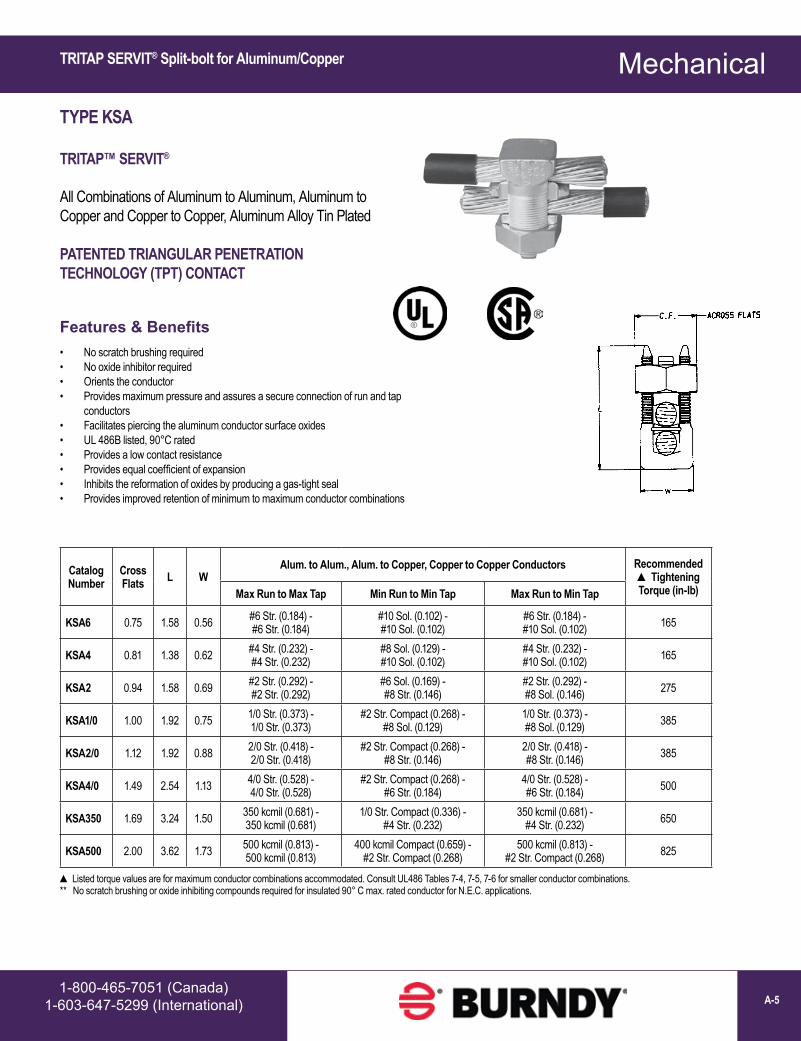
Catalog Number
Cross Flats L W
Alum. to Alum., Alum. to Copper, Copper to Copper Conductors Recommended ▲ Tightening Torque (in-lb)Max Run to Max Tap Min Run to Min Tap Max Run to Min Tap
KSA6 0.75 1.58 0.56 #6 Str. (0.184) - #6 Str. (0.184)
#10 Sol. (0.102) - #10 Sol. (0.102)
#6 Str. (0.184) - #10 Sol. (0.102) 165
KSA4 0.81 1.38 0.62 #4 Str. (0.232) - #4 Str. (0.232)
#8 Sol. (0.129) - #10 Sol. (0.102)
#4 Str. (0.232) - #10 Sol. (0.102) 165
KSA2 0.94 1.58 0.69 #2 Str. (0.292) - #2 Str. (0.292)
#6 Sol. (0.169) - #8 Str. (0.146)
#2 Str. (0.292) - #8 Sol. (0.146) 275
KSA1/0 1.00 1.92 0.75 1/0 Str. (0.373) - 1/0 Str. (0.373)
#2 Str. Compact (0.268) - #8 Sol. (0.129)
1/0 Str. (0.373) - #8 Sol. (0.129) 385
KSA2/0 1.12 1.92 0.88 2/0 Str. (0.418) - 2/0 Str. (0.418)
#2 Str. Compact (0.268) - #8 Str. (0.146)
2/0 Str. (0.418) - #8 Str. (0.146) 385
KSA4/0 1.49 2.54 1.13 4/0 Str. (0.528) - 4/0 Str. (0.528)
#2 Str. Compact (0.268) - #6 Str. (0.184)
4/0 Str. (0.528) - #6 Str. (0.184) 500
KSA350 1.69 3.24 1.50 350 kcmil (0.681) - 350 kcmil (0.681)
1/0 Str. Compact (0.336) - #4 Str. (0.232)
350 kcmil (0.681) - #4 Str. (0.232) 650
KSA500 2.00 3.62 1.73 500 kcmil (0.813) - 500 kcmil (0.813)
400 kcmil Compact (0.659) - #2 Str. Compact (0.268)
500 kcmil (0.813) - #2 Str. Compact (0.268) 825
▲ Listed torque values are for maximum conductor combinations accommodated. Consult UL486 Tables 7-4, 7-5, 7-6 for smaller conductor combinations.** No scratch brushing or oxide inhibiting compounds required for insulated 90° C max. rated conductor for N.E.C. applications.
TRITAP SERVIT® Split-bolt for Aluminum/Copper
TYPE KSA
TRITAP™ SERVIT®
All Combinations of Aluminum to Aluminum, Aluminum to Copper and Copper to Copper, Aluminum Alloy Tin Plated
PATENTED TRIANGULAR PENETRATION TECHNOLOGY (TPT) CONTACT
Features & Benefits• No scratch brushing required• No oxide inhibitor required• Orients the conductor• Provides maximum pressure and assures a secure connection of run and tap
conductors• Facilitates piercing the aluminum conductor surface oxides• UL 486B listed, 90°C rated• Provides a low contact resistance• Provides equal coefficient of expansion• Inhibits the reformation of oxides by producing a gas-tight seal• Provides improved retention of minimum to maximum conductor combinations

Mechanical
www.burndy.com1-800-346-4175 (US)A-6
OKLIP™ Connectors Copper/Copperweld OKLIP™ Connectors Copper/Aluminum/ACSR/AAAC/5005
Catalog Number
Conductor
H J L W
Rec. Tightening
Torque (in-lb)
Run Tap Run Tap
Copper & Alum
ACSR, AAAC, &
5005Copper & Alum
ACSR, AAAC, & 5005
Copper Sol.,
Copperweld Sol.
Steel Nom. Dia.
Copper Sol.,
Copper-weld Sol.
Steel Nom. Dia.
KVSU26 2 Str. - 2/0 Str. 3 - 2/0 6 Str. - 2/0 Str. 6 - 2/0 1 - 3/0 5/16 - 7/16 #6 - 3/0 3/16 -
7/16 2 5/16 1 1-1/2 180
KVSU28 1/0 Str. - 4/0 Str. 1/0 - 4/0 6 Str. - 4/0 Str. 6 - 4/0 2/0 - 4/0 3/8 - 1/2 #6 - 4/0 5/32 - 1/2 2-3/8 3/8 1-1/8 1-3/4 250
KVSU31 250 - 350 kcmil 4/0 - 300 #6 - 350 6 - 300 - 9/16 - 5/8 #6 - 4/0 3/16 - 5/8 2-5/8 1/2 1-3/8 2-1/8 325
KVSU34 400 - 500 kcmil 336.4 - 397.5 #4 - 500 5 - 397.5 - 3/4 - 3/4 #4 - 4/0 7/32 - 3/4 3 1/2 1-1/2 2-1/4 375
KVSU40 400 - 800 kcmil 4/0 - 800 4/0 - 800 3/0 - 715.5 - 3/4 - 1 - 1/2 - 1 3-1/2 1/2 1-5/8 2-1/2 500
KVSU44 500 - 1000 kcmil 4/0 - 1000 4/0 - 1000 kcmil 4/0 - 900 - 7/8 - 1
1/8 - 1/2 - 1 1/8 4 3/8 2 3 500
See note LIGHTNING PROTECTION INFO.
TYPE KVS
OKLIP™
Copper & Copperweld
Compact, two-piece, high strength, high copper alloy BURNDY® OKLIP™ recommended for heavy duty connections. Neoprene rings hold DURIUM™ silicon bronze bolts in place during installation. Installed with ordinary wrench.
TYPE KVSU
UNIVERSAL OKLIP™
All Combinations of Copper, Aluminum, ACSR, AAAC & 5005
Compact, high strength, tin plated copper alloy two-piece connector with spacer and tin-plated silicon bronze DURIUM™ hardware. Recommended for heavy duty connections. Spacer separates dissimilar conductors and provides long contact length. Neoprene ring prevents loss of shorter bolt during installation. Longer peened bolt permits swivel action for easier installation. Use of PENETROX™ joint compound recommended with aluminum and ACSR.
Catalog Number
Conductor ▲ Recommended
Tightening Torque (in-lb)
Copper CopperweldMax Run & Tap
Run Tap Sol. Str. Type VKVS26 2 Str. - 2/0 Str. 6 Str. - 2/0 Str. 3/0 7 #8 — 180KVS28 1/0 Str. - 4/0 Str. 10 Str. - 4/0 Str. 4/0 7 #6 V3/0 250KVS31 250 - 350 kcmil 10 Str. - 350 kcmil — 19 #8 V250 325KVS34 400 - 500 kcmil 10 Str. - 500 kcmil — 19 #6 V350 375KVS40 400- 800 kcmil 3/0 Str. - 800 kcmil — 19 #5 — 500KVS44 500 - 1000 kcmil 3/0 Str. - 1000 kcmil — — — 500
▲ Listed torque values are for maximum conductor combinations accommodated. Consult UL486 Tables 7-4, 7-5, 7-6 for smaller conductor combinations. See note LIGHTNING PROTECTION INFO.
Accommodates compressed conductors within diameter range.

Mechanical
1-800-465-7051 (Canada)1-603-647-5299 (International) A-7
OKLIP™ Connectors Copper/CopperweldOKLIP™ Connectors for Aluminum
See note LIGHTNING PROTECTION INFO.
Catalog Number
Conductor Recommended Tightening Torque (in-lb)Run Tap
KVSW26 2 Str. - 2/0 Str. 6 Sol. - 2/0 Str. 180KVSW28 1/0 Str. - 4/0 Str. 6 Sol. - 4/0 Str. 250KVSW31 250 - 350 kcmil 4 Sol. - 350 kcmil 325KVSW34 400 - 500 kcmil 4 Str. - 500 kcmil 375KVSW40 400 - 800 kcmil AWG 4/0 - 800 kcmil 500KVSW44 500 - 1000 kcmil 250 - 1000 kcmil 500 See note LIGHTNING PROTECTION INFO.
Catalog Number
Conductor
Rec. Tightening
Torque (in-lb)
Conductor Range by Diameter
H J L W
Run Tap Min. Run Dia.
Min. Tap Dia.
Max. Run &
Tap Dia.Copper,& Alum.†
ACSR†,AAAC, & 5005
Copper,& Alum.†
ACSR†,AAAC & 5005
KVS26A 2 Str. - 2/ 0 Str. #4 - 2/0 10 Str. - 2/0 Str. #6 - 2/0 180 0.28 0.12 0.45 2-1/4 5/16 1-1/4 1-5/8KVS28A 1/0 Str. - 4/0 Str. 1/0 - 4/0 10 Str. - 4/0 Str. #6 - 4/0 240 0.36 0.12 0.56 3 3/8 1-5/8 2-1/16KVS31A 250 - 350 4/0 - 336.4 6 Str. - 350 kcmil #6 - 336.4 kcmil 300 0.57 0.18 0.68 3-1/16 1/2 1-15/16 2-7/16KVS34A 400 - 500 336.4 - 397.5 4 Str. - 500 kcmil #5 -397.5 kcmil 300 0.73 0.22 0.81 3-9/16 1/2 2-5/16 2-5/8KVS40A 400 - 800 336.4 - 715.5 kcmil 3/0 Str. - 800 kcmil #3/0 - 715.5 300 0.73 0.47 1.04 4-1/16 1/2 2-7/16 2-7/8KVS44A 500 - 1000 397.5 - 900 kcmil 3/0 Str. - 1000 kcmil #3/0 - 900 kcmil 480 0.80 0.47 1.16 4-7/8 5/8 2-1/2 3-1/8
† Accommodates compressed conductors within diameter range.
THESE CONNECTORS CAN ACCOMMODATE ACSR CONDUCTORS OVER ARMOR ROD WITHIN THE DIAMETER RANGE INDICATED.APPLICATION OVER ARMOR ROD
TYPE KVSW
OKLIP™
Copper and Copperweld
Similiar to OKLIP™ Type KVS except for a high copper alloy spacer that separates run and tap conductors. Provides high contact pressure, confines conductor strands, and assures vibration-proof connection. Longer peened bolt, permits swivel action for easier installation. Silicon bronze DURIUM™ hardware.
TYPE KVS-A
ALUMINUM OKLIP™
All Combinations of Copper, Aluminum†, ACSR†, AAAC and 5005
Three-piece, high-conductivity, non-copper bearing aluminum alloy connector with thick spacer and aluminum hardware. Hardware in KVS26A and KVS28A is stainless steel. Recommended for heavy duty dissimilar metal applications. Spacer separates conductors and provides long contact length. Belled entrances prevent chafing, permit easier assembly of conductors. Longer peened bolt permits swivel action for easier installation. Neoprene ring prevents loss of shorter bolt. PENETROX™ joint compound recommended with aluminum and ACSR.

Mechanical
www.burndy.com1-800-346-4175 (US)A-8
Catalog Number
Copper ConductorFig. No.
Dimensions Rec. Tightening
Torque in-lb ▲
Conductor
Run Tap H J L WRun Tap
Copperweld Copperweld - Copper Copperweld Copperweld
- Copper
QPX2C2C 6 Str. - 2 Str. 6 Str. - 2 Str.
1
1-1/25/16 1-5/16
1-3/8 150 5 Sol. - 3 #7 8A - 4A5 Sol. - 3 #7 8A - 4A
QPX282C 1 Str. - 4/0 Str. 6 Str. - 2 Str. 2-1/16 1-9/16250 7 #9 - 7 #5 3A - 3/0V
QPX2828 1 Str. - 4/0 Str. 1 Str. - 4/0 Str.2-3/8
3/8 1-13/16 1-13/16 7 #9 - 7 #5 3A - 3/0V
QPX342C 250 - 500 kcmil 6 Str. - 2 Str. 5/16 1-3/8 1-7/8
375 19 #19 - 19 #6 4/0 EK
5 Sol. - 3 #7 8A - 4A
QPX3428 250 - 500 kcmil 1 Str. - 4/0 Str. 2-3/43/8
1-3/4 2-1/16 7 #9 - 7 #5 3A - 3/0 V
QPX3434 250 - 500 kcmil 250 - 500 kcmil 2 3 2-1/16 2-3/16 19 #19 - 19 #6 4/0 EK
QPX442C 500 - 1000 kcmil 6 Str. - 2 Str.
12-11/16 5/16 1-3/8 2-1/4
500 19 #6 —
5 Sol. - 3 #7 8A - 4A
QPX4428 500 - 1000 kcmil 1 Str. - 4/0 Str. 2-7/8
3/8
1-13/162-7/16
7 #9 - 7 #5 3A - 3/0V
QPX4434 500 - 1000 kcmil 250 - 500 kcmil
23-1/16 2-1/16 19 #19 - 19 #6 4/0 EK
QPX4444 500 - 1000 kcmil
500 - 1000 kcmil 3-7/16 2-5/8 2-9/16 19 #6 —
▲ Listed torque values are for maximum conductor combinations accommodated. Consult UL486 Tables 7-4, 7-5, 7-6 for smaller conductor combinations.
See note LIGHTNING PROTECTION INFO.
Fig. 1 Fig. 2
* For various configurations, see page with TYPE QPX-Y
TYPE QPX
VERSITAP™
Copper, Copperweld, Copperweld-Copper
The VERSITAP™ Type QPX is recommended for Tee, Cross, Parallel, Butt and Tap connections. Range-taking, only 10 connectors required to accommodate conductor sizes from #6 Str. to 1000 kcmil. Edges are rounded for easy taping. Made of high strength, high-conductivity copper alloy and silicon bronze DURIUM™ hardware.
VERSITAP™ Parallel Clamps for Copper/Copperweld

Mechanical
1-800-465-7051 (Canada)1-603-647-5299 (International) A-9
Catalog Number Run Tap
Fig.No. H J L W
Recommended Tightening
Torque in-lb ▲QPX2C2CY 6 Str.-2 Str. 6 Str.-2 Str. 1 1-5/8 5/16 1-1/2 1-5/8 150QPX282CY 1 Str. - 4/0 Str. 6 Str.-2 Str. 1 1-7/8 5/16 1-1/2 1-7/8 150QPX2828Y 1 Str. - 4/0 Str. 1 Str. - 4/0 Str. 1 2 3/8 2 2-1/8 250QPX342CY 250 - 500 kcmil 6 Str.-2 Str. 1 2-1/4 5/16 1-1/2 2-1/8 375QPX3428Y 250 - 500 kcmil 1 Str. - 4/0 Str. 1 2-1/2 3/8 2 2-1/2 375QPX3434Y 250 - 500 kcmil 200 - 500 kcmil 2 2-7/8 3/8 2-1/2 2-5/8 375QPX4444Y 750 - 1000 kcmil 750 - 1000 kcmil 2 3-7/8 1/2 3-1/2 3-1/2 500
Fig. 1 Fig. 2
▲ Listed torque values are for maximum conductor combinations accommodated. Consult UL486 Tables 7-4, 7-5 7-6 for smaller conductor combinations. See note LIGHTNING PROTECTION INFO.
APPLICATION VARIATIONS
PARALLEL
SPLICE
CROSSTAP
TEE
Universal VERSITAP™ Parallel Clamps for Copper/Aluminum
TYPE QPX-Y
UNIVERSAL VERSITAP™
Universal Parallel Clamp For Copper and Aluminum
High copper alloy cast connector, tin-plated for use with copper or aluminum cable. Makes parallel, tap, tee, cross or end-to-end connections. Edges rounded for easy taping. PENETROX™ joint compound recommended.

Mechanical
www.burndy.com1-800-346-4175 (US)A-10
Catalog Number
Copper Conductor B H J T
(Max) WQGFL1CB1 #10 Sol-#1 Str 1-1/8 1-7/8 3/8 1/4 1
QGFL1CB1T6 #10 Sol-#1 Str 1-1/8 2-3/8 3/8 3/4 1QGFL26B1 #8 Sol-#2/0 Str 1-1/4 2-1/8 3/8 1/4 1-1/8
QGFL26B1T6 #8 Sol-#2/0 Str 1-1/4 2-5/8 3/8 3/4 1-1/8QGFL26B2* #8 Sol-#2/0 Str 1-1/4 2-5/16 1/2 1/4 1-1/8
QGFL26B2T6* #8 Sol-#2/0 Str 1-1/2 2-13/16 1/2 3/4 1-1/8QGFL29B1* #6 Str-250 kcmil 1-3/8 2-5/8 1/2 1/4 1-3/8
QGFL29B1T6* #6 Str-250 kcmil 1-5/8 3-1/8 1/2 3/4 1-3/8QGFL31B1* 2 AWG-350 kcmil 1-3/4 2-7/8 1/2 1/4 1-5/8
QGFL31B1T6* 2 AWG-350 kcmil 1-3/4 3-1/4 1/2 3/4 1-5/8QGFL34B1 1/0 -500 kcmil 2 3-1/8 1/2 1/4 1-3/4
QGFL34B1T6 1/0 -500 kcmil 2 3-5/8 1/2 3/4 1-3/4QGFL39B1 350 kcmil-750 kcmil 2-1/4 3-1/4 1/2 1/4 1-3/4
QGFL39B1T6 350 kcmil-750 kcmil 2-1/4 3-5/8 1/2 3/4 1-3/4QGFL44B1 750 kcmil-1000 kcmil 2-1/4 3-3/8 1/2 1/4 2-1/8
QGFL44B1T6 750 kcmil-1000 kcmil 2-1/4 4-1/8 1/2 3/4 2-1/8QGFL46B1 1000 kcmil-1500 kcmil 2-1/4 4 1/2 1/4 2-1/2
QGFL46B1T6 1000 kcmil-1500 kcmil 2-1/4 4-1/2 1/2 3/4 2-1/2QGFL48B1 1500 kcmil-2000 kcmil 2-1/4 4-3/4 1/2 1/4 3
* Can be installed side by side or in-line on NEMA drilled bar.
Catalog Number
Fig. No.
A Diameter
H Ref. L P
FCB634N 1 0.50 5.25 3.75 2.25FCB636N 2 0.50 5.25 5.50 2.25FCB644N 1 0.75 5.75 4.00 2.75FCB646N 2 0.75 5.75 5.75 2.75FCB654N 1 1.00 7.00 4.25 4.00FCB632NP300 Not Shown 0.50 5.00 3.50 3.00FCB6444NP50 Not Shown 0.75 9.00 5.00 5.00
NOTE: All pads are NEMA drilled.
Fig. 1
Fig. 2
TYPE QGFL
BARTAP™
Copper Cable to Flat Bar or Pad
High copper alloy BARTAP™ for joining a range of cable to bar or pad. One-wrench installation. DURIUM™ nut and lockwasher
TYPE FCB
TRANSFORMER TAP ADAPTER
Copper and Aluminum
Cast in one piece from copper alloy. Transformer tap adapter designed to accommodate from 1 to 6 NEMA drilled copper or aluminum terminal taps from a single secondary transformer outlet. Tin-plated. Order mounting hardware and tap terminals separately.
BARTAP™ for Copper Cable to Flat Bar/Pad; Transformer Tap Adapter for Copper/Aluminum
Mechanical
1-800-465-7051 (Canada)1-603-647-5299 (International) A-11
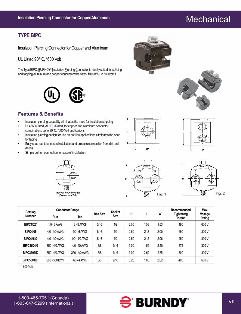
Catalog Number
Conductor RangeBolt Size Socket
Size H L WRecommended
Tightening Torque
Max. Voltage RatingRun Tap
BIPC1/02* 1/0 - 8 AWG 2 - 8 AWG 5/16 1/2 2.00 1.53 1.53 180 600 V
BIPC4/06 4/0 - 1/0 AWG 1/0 - 6 AWG 5/16 1/2 2.50 2.12 2.00 250 300 V
BIPC4/01/0 4/0 - 1/0 AWG 4/0 - 1/0 AWG 5/16 1/2 2.50 2.12 2.06 250 300 V
BIPC3504/0 350 - 4/0 AWG 4/0 - 10 AWG 3/8 9/16 3.00 1.59 2.50 375 300 V
BIPC350350 350 - 4/0 AWG 350 - 4/0 AWG 3/8 9/16 3.00 2.62 2.75 300 300 V
BIPC5004/0* 500 - 350 kcmil 4/0 - 4 AWG 3/8 9/16 3.25 1.80 2.62 400 600 V
Fig. 1 Fig. 2
* 600 Volt
TYPE BIPC
Insulation Piercing Connector for Copper and Aluminum
UL Listed 90° C, *600 Volt
The Type BIPC, BURNDY® Insulation Piercing Connector is ideally suited for splicing and tapping aluminum and copper conductor wire sizes: #10 AWG to 500 kcmil.
Features & Benefits• Insulation piercing capability eliminates the need for insulation stripping• UL486B Listed, AL9CU Rated, for copper and aluminum conductor
combinations up to 90°C, *600 Volt applications• Insulation piercing design for use on hot-line applications eliminates the need
for taping• Easy snap-out tabs eases installation and protects connection from dirt and
debris• Simple bolt-on connection for ease of installation
Insulation Piercing Connector for Copper/Aluminum

Mechanical
www.burndy.com1-800-346-4175 (US)A-12
Catalog Number Wire Range Fig.
No. C D H K Stud Hole Size L N T
Recommended Tightening
Torque (in-lb)KPA8C 14 Sol. - 8 Str. 1 0.38 0.47 0.72 0.21 #10 0.97 0.22 0.06 25KPA4C 14 Sol. - 4 Str. 1 0.50 0.59 0.94 0.27 1/4 1.22 0.30 0.06 35KPA25 4 Str. - 1/0 Str. 2 0.75 0.81 1.25 0.33 5/16 1.82 0.41 0.10 180KPA28 1/0 Str. - 4/0 Str. 2 0.97 1.12 1.66 0.39 3/8 2.40 0.53 0.13 250KPA34 4/0 Str. - 500 kcmil 2 1.38 1.38 2.44 0.54 1/2 3.32 0.75 0.20 375
Fig. 1
Fig. 2
Catalog Number Wire Range
Fig. No. C D H K
Stud Hole Size L N T Hardware
Recommended Tightening
Torque (in-lb)KPA8CUP 14 Sol. - 6 Str.
10.38 0.56 0.81 0.20 #10 1.04 0.22
0.07# 12-24 SLOT 35
KPA4CUP 14 Sol. - 4 Str. 0.50 0.71 1.00 0.28 1/4 1.28 0.33 5/16 DIA.SLOT ROBERTSON 45
NOTE: For tin plating drop “-UP” suffix and add “-TP” suffix (example: KPA4CTP).For use in grounding applications with a green screw, contact factory. Listed for grounding per UL467.
Fig. 1
NOTE: For unplated version add “UNPL” suffix.
TYPE KPA
SCRULUG™
Copper Cable
High copper alloy tin-plated terminal for joining a wide range of cable to equipment pads or terminal blocks. Especially good in light industrial applications. The tongue and body are a one-piece design. The pressure bar equalizes pressure over the conductor and prevents the screw from cutting into the cable
TYPE KPA-UP
SCRULUG™
Copper Cable
High copper alloy terminal for joining a wide range of cable to equipment pads or terminal blocks. Plain copper finish.
Features & Benefits• One piece design for superior torque and pull out performance• Convenient range taking design reduces number of SKUs needed to carry in
stock; one catalog number accommodates several conductor sizes• High conductivity copper alloy for a long lasting, reliable connection• Compact, easy to use design• Slot Robertson screw, hex head, hex socket bolt require no special installation
tools and eliminates over-torquing and potential conductor damage
SCRULUG™ Terminals for Copper; Tin-plated / Unplated

Mechanical
1-800-465-7051 (Canada)1-603-647-5299 (International) A-13
Catalog Number Conductor
Fig. No.
B(MM/IN)
C(MM/IN)
K(MM/IN)
L(MM/IN)
N (MM/IN)
T(MM/IN)
Rec. Tightening
Torque (in-lb) Hardware
Stud Hole Size
Strip Length
(in)KLU25 14 Sol. .064 Dia.to
10 Sol. .102 Dia. CU 3 7.000.28
8.000.31
4.000.14
26.01.02
5.000.21
2.000.07 20 No. 8-32 Slotted Round
Machine Screw #6 7/16KLU25TP
KLU35 14 Sol. .0641 Dia.to6 Str. .184 Dia. CU 2 11.0
0.4310.00.39
5.000.20
31.01.24
6.000.22
2.000.07 35 1/4 UNF Slotted Set
Screw #10 5/8KLU35TPKLU70 8 Sol. .129 Dia. to
2 Str. .292 Dia. CU 2 13.00.50
12.00.47
7.000.26
39.01.55
6.000.25
2.000.08 40 5/16 UNF Slotted Set
Screw 1/4 3/4KLU70TPKLU125 2 Str. .292 Dia. to
1/0 Str. .372 Dia. CU 2 15.00.61
16.00.62
7.000.26
50.01.98
11.00.42
3.000.11 50 3/8 UNF Slotted Set
Screw 1/4 15/16KLU125TPKLU175 4 Str. .232 Dia. to
3/0 Str. .470 Dia. CU 1 18.00.72
19.00.75
10.00.39
56.02.20
11.00.43
4.000.16 250 3/8 UNF Socket/Hex
Screw 3/8 1KLU175TPKLU225 2 Str. .292 Dia. to
4/0 Str. .528 Dia. CU 1 24.00.94
25.00.99
9.000.34
65.02.55
13.00.51
3.000.12 250 7/16 UNF Socket/Hex
Screw 5/16 1-5/16KLU225TPKLU300 1/0 Str. .372 Dia. to
350 kcmil .681 Dia. CU 1 31.01.22
25.00.99
10.00.39
72.02.83
13.00.52
3.000.12 325 5/8 UNF Socket/Hex
Screw 3/8 1-5/8KLU300TPKLU400 1/0 Str. .372 Dia. to
500 kcmil .813 Dia. CU 1 36.01.42
38.01.50
10.00.39
104.04.09
23.00.91
5.000.18 375 5/8 UNF Socket/Hex
Screw 3/8 1-5/32KLU400TP
NOTES: Suffix “-TP” on catalog number denotes tin plate (example: KLU400TP). 2 Material: Copper alloy.1
1
TYPE KLU
SCRULUG™
Copper Cable with Offset Tongue; Non-Plated
High copper alloy terminal with offset tongue for joining a wide range of cable to equipment pads or bar. Easy to install with screwdriver or wrench. Connector is reusable. Plain copper finish.
Features & Benefits• Convenient range-taking design reduces catalog numbers required in
inventory; one connector accommodates several conductor sizes• High conductivity copper alloy for long lasking reliable contact• Compact design, easy to install, reduces labor time• Slot Robertson screw, hex head, hex socket bolt require no special installation
tools and eliminates over-torquing and potential conductor damage
SCRULUG™ Terminals for Copper; Offset Tongue; Unplated/Tin-plated

Mechanical
www.burndy.com1-800-346-4175 (US)A-14
TYPE KA
KA-LUG™
Copper Cable
Compact, economical, high copper alloy terminal for joining a wide range of cable to equipment pads or terminal blocks.
Catalog Number Conductor Fig.
No. C H J KStud Hole Size
L N TRecommended
Tightening Torque (in-lb)
KA8C # 14 Sol. (0.064 Dia.) - 8 Str. (0.416 Dia.) 1 3/8 5/8 #12 7/32 #10 13/16 3/16 3/32 25
KA4C # 14 Sol. (0.064 Dia.) - 4 Str. (0.232 Dia.) 1 9/16 3/4 5/16" 9/32 1/4 1-1/8 1/4 7/64 45
KA25 * # 4 Str. (0.232 Dia.) -1/0 Str. (0.373 Dia.) 2 3/4 15/16 1/2" 27/64 3/8 1-11/16 3/8 1/8 200
KA252TC38 * # 4 Str. (0.232 Dia.) -1/0 Str. (0.373 Dia.) 3 3/4 15/16 1/2" 27/64 3/8 2-13/16 3/8 1/8 200
KA28 * # 1 Str. (0.332 Dia.) -4/0 Str. (0.528 Dia.) 2 15/16 1-1/4 5/8" 27/64 3/8 1-15/16 7/16 3/16 275
KA34 * 4/0 Str. (0.528 Dia.) -500 kcmil (0.814 Dia.) 2 1-3/8 2-3/32 13 /16" 9/16 1/2 2-9/16 9/16 9/32 375
Catalog Number Wire Range
No. of holes in
padC D E H K
Stud Hole Size
L N TRec.
Tightening Torque (in-lb)
EA2C 8 AWG-2 AWG 1 13/16 1-1/16 — 1-3/8 7/16 3/8 2-1/2 13/32 1/4 150EA25 2 AWG-1/0 1 7/8 1-1/8 — 1-7/16 7/16 3/8 2-11/16 7/16 1/4 180EA28 1/0 -4/0 AWG 1 1-1/16 1-3/8 — 1-3/4 7/16 3/8 3-3/16 17/32 5/16 250EA282N 1/0 -4/0 AWG 2 1-1/16 3-5/8 1-3/4 1-3/4 9/16 1/2 5-1/8 5/8 5/16 250EA34 250 kcmil-500 kcmil 1 1-3/8 1-5/8 — 2-1/4 9/16 1/2 4 13/16 3/8 375EA342N 250 kcmil-500 kcmil 2 1-3/8 3-5/8 1-3/4 2-1/4 9/16 1/2 5-5/8 5/8 3/8 375
▲ Listed torque values are for maximum conductor sizes accommodated. Consult UL486 Tables 7-4, 7-5, 7-6 for smaller conductor sizes.* Not CSA Certified
* “N” indicates NEMA standard stud holes.▲ Listed torque values are for maximum conductor sizes accommodated. Consult UL486 Tables 7-4, 7-5, 7-6 for smaller conductor sizes.
Fig. 1 Fig. 2 Fig. 3
TYPE EA
VERSILUG™
Copper Cable
Compact, high copper alloy terminal for joining a wide range of cable to equipment pads or bar. Clamping element adjustable to several angles. One-wrench installation.
KA-LUG™ Terminals for Copper; VERSILUG™ Terminals for Copper - Adjustable for Angled Orientation

Mechanical
1-800-465-7051 (Canada)1-603-647-5299 (International) A-15
Catalog Number* Conductor Holes in Pad C D E & F H K
Stud Hole Size
L LL N T Torque (in-lb)Type QA Type QQA Commercial Navy
QA8CB QQA8C 14 Sol. - 8 Str. 4-14 1 9/16 9/16 — 11/16 7/32 #10 1-3/8 2-5/16 9/32 5/32 75QA8C2B — 14 Sol. - 8 Str. 4-14 2 9/16 1-1/14 5/8 11/16 7/32 #10 2 3 5/16 5/32 75QA4CB — 8 Str. - 4 Str. 23-40 1 5/8 5/8 — 3/4 9/32 1/4 1-7/16 2-3/8 5/16 3/16 110QA4C2B QQA4C2 8 Str. - 4 Str. 23-40 2 5/8 1-3/16 5/8 3/4 9/32 1/4 2 2-15/16 5/16 3/16 110QA1CB QQA1C 4 Str. - 1 Str. 50-75 1 5/8 3/4 — 1 9/32 1/4 1-3/4 2-13/16 11/32 7/32 150QA1C2B QQA1C2 4 Str. - 1 Str. 50-75 2 5/8 1-9/16 7/8 1 11/32 5/16 2-9/16 3-5/8 11/32 7/32 150QA26B QQA26 1/0 Str. - 2/0 Str. 100-125 1 13/16 1 — 1-3/16 13/32 3/8 2 3-3/16 7/16 7/32 180QA262B QQA262 1/0 Str. - 2/0 Str. 100-125 2 13/16 1-15/16 1 1-3/16 13/32 3/8 3 4-3/16 7/16 7/32 180QA28B QQA28 3/0 Str. - 4/0 Str. 150-200 1 1 1-1/16 — 1-5/16 13/32 3/8 2-1/4 3-9/16 17/32 1/4 250QA282B — 3/0 Str. - 4/0 Str. — 2 1 2 1 1-9/29 13/32 3/8 3-1/5 — 7/16 1/4 250QA282N* QQA282N* 3/0 Str. - 4/0 Str. 150-200 2 1 3-1/8 1-3/4 1-5/16 9/16 1/2 4-5/16 5-5/8 5/8 1/4 250QA31B QQA31 250 - 350 kcmil 250-350 1 1-3/16 1-3/8 — 1-11/16 17/32 1/2 2-11/36 4-1/8 11/16 5/16 325QA312B — 250 - 350 kcmil 250-350 2 1-3/16 1-31/32 1 1-11/16 7/16 3/8 3-3/8 — 7/16 5/16 325QA312N QQA312N* 250 - 350 kcmil 250-350 2 1-3/16 3 1-3/4 1-11/16 9/16 1/2 4-7/16 5-7/8 5/8 5/16 325QA34B — 400 - 500 kcmil 400-500 1 1-3/8 1-5/8 — 2 17/32 1/2 3-3/16 4-7/8 13/16 5/16 375QA342B — 400 - 500 kcmil 400-500 2 1-3/8 2 1 2 13/32 3/8 3-9/16 — 7/16 5/16 375QA344B QQA34 400 - 500 kcmil 400-500 4 1-7/8 1-15/16 1 2 7/16 3/8 3-1/2 — 7/16 5/16 375QA342N* QQA342N* 400 - 500 kcmil 400-500 2 1-3/8 3-3/32 1-3/4 2 9/16 1/2 4-11/16 6-9/32 5/8 5/16 375QA40B — 600 - 800 kcmi 650-800 1 1-5/8 1-7/8 — 2-7/16 11/16 5/8 3-11/16 — 27/32 3/8 500QA402N* QQA402N* 600 - 800 kcmi 650-800 2 1-5/8 3 1-3/4 2-7/16 9/16 1/2 4-14/16 7-3/32 5/8 3/8 500QQA404N* — 600 - 800 kcmi 650-800 4 3 3 1-3/4 2-7/16 9/16 1/2 — 7-3/32 5/8 3/8 500QA44B — 850 - 1000 kcmil 1000 1 1-7/8 2 — 2-3/4 11/16 5/8 3-15/16 — 1 1/2 500QA442N* QQA442N* 850 - 1000 kcmil 1000 2 1-7/8 3 1-3/4 2-3/4 9/16 1/2 5 7-1/8 5/8 1/2 500QA444N* QQA444N* 850 - 1000 kcmil 1000 4 3 3-1/16 1-3/4 2-3/4 9/16 1/2 5 7-1/8 5/8 1/2 500QA462N* — 1100 - 1500 kcmil 1300 2 2-1/8 3 1-3/4 3-1/8 9/16 1/2 5-1/4 — 5/8 9/16 600QA46B — 1100 - 1500 kcmil 1300 1 2-1/8 2-1/8 — 3-1/8 13/16 3/4 4-3/8 — 1-1/16 9/16 600
* ‘‘N’’ indicates NEMA standard stud holes. All 4N items see note LIGHTNING PROTECTION INFO.
TYPES QA, QQA
QIKLUG™
Copper Cable
Type QA heavy duty, compact, high copper alloy terminal for joining a wide range of cable to equipment pads or bar. Fast one-wrench installation. Type QQA heavy duty, high copper alloy terminal for joining cable to equipment pads or bar. Twin clamping elements secure joint vibration and flexing. One-wrench installation.
Type QQA
Type QA
LL
L
QIKLUG™ Terminals for Copper; Single or Twin Clamping Elements

Mechanical
www.burndy.com1-800-346-4175 (US)A-16
Catalog Number* Conductor
No. of Holes in
PadC D E & F H K
Stud Hole Size
L N T WRecommended
Tightening Torque in-lb
Q2A1C2 4 Str. - 1 Str.2
1-1/2 1-7/8 1 1-1/16 7/16 3/8 2-7/8 7/16 7/32 1-13/16 150Q2A262N 1/0 Str. - 2/0 Str. 1-5/8
3-1/8
3/4 1-3/16
9/16 1/2
4-3/16
5/8
1-15/16 180Q2A282N 3/0 Str. - 4/0 Str. 1-7/8
1-3/4
1-3/8 4-3/8 1/4 250Q2A284N 4 34-1/2 2-1/8Q2A312N 250 - 350 kcmil 2 2-3/8 1-11/16 5/16 325Q2A314N 4 3 3Q2A342N 400 - 500 kcmil 2 2-1/2 2 4-11/16 3/8 375Q2A344N 4
3 3-3/4Q2A402N 600 - 800 kcmil 2 2-7/16 5 7/16 500Q2A404N4 4-11/32Q2A444N 850 - 1000 kcmil 3-1/4 2-3/4 5-1/4 1/2
Q2A464N 1100 - 1500 kcmil 3-1/2 3-1/4 3-1/8 5-1/2 11/16 5 600
Catalog Number* Conductor
No. of Holes in
PadC D E & F H K
Stud Hole Size
L N T WRecommended
Tightening Torque in lb
Q3A282N 3/0 Str. - 4/0 Str. 2 1-7/8
3-1/81-3/4
1-3/8
9/16 1/2
4-5/16
5/8
1/4 3-3/16 250Q3A284N 3/0 - 4/0 Str. 4 3 4-3/8Q3A312N 250 - 350 kcmil 2 2-3/8 1-11/16 4-7/16 5/16 4-1/16 325Q3A314N 4 3Q3A342N 400 - 500 kcmil 2 2-1/2 1-15/16 4-3/4 3/8 4-9/16 375Q3A344N
43Q3A404N 600 - 800 kcmil 2-7/16 5 7/16 5-13/16 500Q3A444N 850 - 1000 kcmil 3-1/4 2-3/4 5-1/4 1/2 6-5/8
Q3A464N 1100 - 1500 kcmil 3-1/2 3-1/4 3-1/8 5-1/2 11/16 7-7/8 600
* ‘‘N’’ indicates NEMA standard stud holes. All 4N items see note LIGHTNING PROTECTION INFO.
* ‘‘N’’ indicates NEMA standard stud holes.
TYPE Q2A
QIKLUG™
Copper Cable
Compact, high copper alloy terminal for joining two cables to equipment pads or bars. Each element accommodates a wide range of cable. One-wrench installation.
TYPE Q3A
QIKLUG™
Copper Cable
Compact, high copper alloy terminal for joining three cables to equipment pads or bar. Each element accommodates a wide range of cable. One-wrench installation.
QIKLUG™ Terminals for Copper; Two or Three Conductor Designs

Mechanical
1-800-465-7051 (Canada)1-603-647-5299 (International) A-17
Catalog Number* Conductor
No. of Holes in
PadC D E H K
Stud Hole Size
L N TRecommended
Tightening Torque in-lb
QB8C 14 Sol. - 8 Str. 1 9/16 9/16 — 7/8 7/32 #10 1-1/8 9/32 5/32 75QB4C 8 Str. - 4 Str. 1 11/16 27/32 — 13/16 9/32 1/4 1-3/8 11/32 1/4 110QB1C 4 Str. - 1 Str. 1 11/16 13/16 — 1 9/32 1/4 1-1/2 11/32 7/32 150QB26 1/0 Str. - 2/0 Str. 1 13/16 1 — 1-1/32 13/32 3/8 1-13/16 7/16 7/32 180QB28 3/0 Str. - 4/0 Str. 1 1 1-1/16 — 1-5/16 13/32 3/8 2-1/16 17/32 1/4 250
QB312N 250 - 350 kcmil 2 13/16 3-1/4 1-3/4 1-11/16 9/16 1/2 4-1/2 5/8 5/16 325* ‘‘N’’ indicates NEMA standard stud holes.
Catalog Number* Conductor
No. of Holes in
PadC D E & F H K
Stud Hole Size
L N TRecommended
Tightening Torque in-lb
Q2B282N 3/0 Str. - 4/0 Str. 2 1-7/8 3-1/8 1-3/4 1-3/8 9/16 1/2 5-3/16 5/8 1/4 250Q2B312N 250 - 350 kcmil 2 2-3/8 3-3/16 1-11/16 1-3/8 9/16 9/16 5-7/8 5/8 5/16 325Q2B404N 600 - 800 kcmil 4 3 3-1/16 1-3/8 2-5/16 9/16 3/4 6-11/16 5/8 7/16 500
* ‘‘N’’ indicates NEMA standard stud holes. All 4N items see note LIGHTNING PROTECTION INFO.
TYPE QB
QIKLUG™
Copper Cable
Compact, high copper alloy side entrance terminal for joining a range of cable at right angles to terminal blocks. One-wrench installation.
TYPE Q2B
QIKLUG™
Copper Cable
Compact, high copper alloy terminal for joining two cables at right angles to a single terminal block. Each element accommodates a range of cable. One-wrench installation.
QIKLUG™ Terminals for Copper; Side Entry (90° Right Angle);One or Two Conductor Designs
Mechanical
www.burndy.com1-800-346-4175 (US)A-18
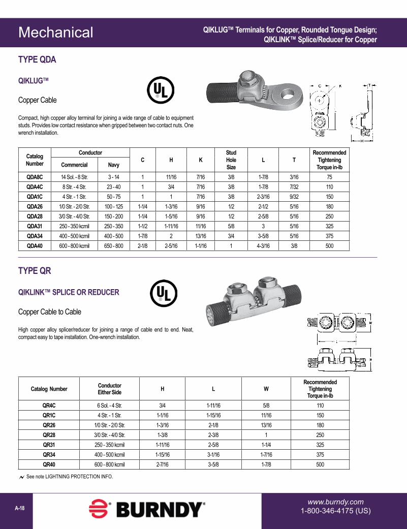
Catalog Number
ConductorC H K
Stud Hole Size
L TRecommended
Tightening Torque in-lbCommercial Navy
QDA8C 14 Sol. - 8 Str. 3 - 14 1 11/16 7/16 3/8 1-7/8 3/16 75QDA4C 8 Str. - 4 Str. 23 - 40 1 3/4 7/16 3/8 1-7/8 7/32 110QDA1C 4 Str. - 1 Str. 50 - 75 1 1 7/16 3/8 2-3/16 9/32 150QDA26 1/0 Str. - 2/0 Str. 100 - 125 1-1/4 1-3/16 9/16 1/2 2-1/2 5/16 180QDA28 3/0 Str. - 4/0 Str. 150 - 200 1-1/4 1-5/16 9/16 1/2 2-5/8 5/16 250QDA31 250 - 350 kcmil 250 - 350 1-1/2 1-11/16 11/16 5/8 3 5/16 325QDA34 400 - 500 kcmil 400 - 500 1-7/8 2 13/16 3/4 3-5/8 5/16 375QDA40 600 - 800 kcmil 650 - 800 2-1/8 2-5/16 1-1/16 1 4-3/16 3/8 500
Catalog Number Conductor Either Side H L W
Recommended Tightening Torque in-lb
QR4C 6 Sol. - 4 Str. 3/4 1-11/16 5/8 110QR1C 4 Str. - 1 Str. 1-1/16 1-15/16 11/16 150QR26 1/0 Str. - 2/0 Str. 1-3/16 2-1/8 13/16 180QR28 3/0 Str. - 4/0 Str. 1-3/8 2-3/8 1 250QR31 250 - 350 kcmil 1-11/16 2-5/8 1-1/4 325QR34 400 - 500 kcmil 1-15/16 3-1/16 1-7/16 375QR40 600 - 800 kcmil 2-7/16 3-5/8 1-7/8 500
See note LIGHTNING PROTECTION INFO.
TYPE QDA
QIKLUG™
Copper Cable
Compact, high copper alloy terminal for joining a wide range of cable to equipment studs. Provides low contact resistance when gripped between two contact nuts. One wrench installation.
TYPE QR
QIKLINK™ SPLICE OR REDUCER
Copper Cable to Cable
High copper alloy splicer/reducer for joining a range of cable end to end. Neat, compact easy to tape installation. One-wrench installation.
QIKLUG™ Terminals for Copper, Rounded Tongue Design;QIKLINK™ Splice/Reducer for Copper

Mechanical
1-800-465-7051 (Canada)1-603-647-5299 (International) A-19
Catalog Number*Conductor
No. ofHoles in Pad
C D E&F H KStud Hole Size
L LL N TRec.
Tightening TorqueType VA Type VVA
VA2C VVA2C 8 AWG-2 AWG 1 13/16 1-1/4 — 1-1/2 7/16 3/8 2-3/4 4-1/16 13/32 1/4 275VA25 VVA25 6 AWG-1/0 1 7/8 1-5/16 — 1-7/8 7/16 3/8 2-7/8 4-5/16 7/16 1/4 385VA28 VVA28 1/0 -4/0 AWG 1 1-1/16 1-1/2 — 2-1/4 7/16 3/8 2-7/8 4-1/8 17/32 5/16 250
VA282N VVA282N 1/0 -4/0 AWG 2 1-1/16 3-1/2 1-3/4 2-1/4 9/16 1/2 4-15/16 6-1/5 5/8 5/16 250VA30 VVA30 1/0 -300 kcmil 1 1-1/8 1-5/8 — 2-3/16 7/16 3/8 3-1/4 4-5/8 5/8 5/16 325
VA302N VVA302N 1/0 -300 kcmil 2 1-1/8 3-9/16 1-3/4 2-3/16 9/16 1/2 5-3/16 6-9/16 5/8 5/16 325VA34 VVA34 300 kcmil-500 kcmil 1 1-3/8 2 — 3-11/32 9/16 1/2 3-13/16 5-5/16 13/16 3/8 375
VA342N VVA342N 300 kcmil-500 kcmil 2 1-3/8 3-5/8 1-3/4 3-11/32 9/16 1/2 5-3/8 6-7/8 5/8 3/8 375VA344N VVA344N 300 kcmil-500 kcmil 4 3 3-5/8 1-3/4 3-11/32 9/16 1/2 5-3/8 6-7/8 5/8 3/8 375
VA40 VVA40 500 kcmil-800 kcmil 1 1-5/8 2-5/16 — 2-7/8 11/16 5/8 4-1/2 6-3/8 15/16 3/8 500VA402N VVA402N 500 kcmil-800 kcmil 2 1-5/8 3-5/8 1-3/4 2-7/8 9/16 1/2 5-13/16 7-11/16 5/8 3/8 500VA404N VVA404N 500 kcmil-800 kcmil 4 3 2-5/8 1-3/4 2-7/8 9/16 1/2 5-13/16 7-11/16 5/8 3/8 500
All 4N items see note LIGHTNING PROTECTION INFO.* “N” indicates NEMA standard stud holes.
Type VA Type VVA
TYPES VA, VVA
VARILUG™
Copper Cable
High copper alloy terminal for joining a wide range of cable to equipment pads or bar. Particularly suitable for use on extra flexible cable. One-wrench installation. Type VVA, twin elements secure joint against vibration and flexing. Particularly recommended for use on extra flexible cables. One-wrench installation.
VARILUG™ Terminals for Copper; Single or Twin Clamping Elements

Mechanical
www.burndy.com1-800-346-4175 (US)A-20
TYPE CL501 & CL501TN
COPPER LAY-IN QIKLUG™
Copper
The Lay-In QIKLUG™ is manufactured from high strength pure electrolytic copper to ensure maximum strength and conductivity. UL467 Listed for direct burial in earth or concrete. The open-faced design allows for fast lay-in of the conductor without the need for cutting or breaking. Stainless steel screws used for excellent corrosion resistance.
Catalog Number
Conductor Range
Stud Hole
CL501 14 AWG-4 AWG #10
CL501TN 14 AWG-4 AWG #10
Photo above shows a typical solar panel installation using CL50-1 connectors.
Catalog Number
Wire Range Copper H W L T K
Dia Hex Size
CL1/014TN #14 - 1/0 AWG 1.17 0.60 1.50 0.22 0.27 7/16-20 (Slotted)
CL3/0516TN #6 - 3/0 AWG 1.56 0.80 2.00 0.30 0.33 9/16-18 (0.25 Hex)
CL250516TN #6 AWG - 250 kcmil 1.79 0.80 2.20 0.30 0.33 9/16-18 (0.25 Hex)
TYPE CL
COPPER LAY-IN QIKLUG™
Copper
Manufactured for maximum strength and conductivity, these lay-in lugs allow for continuous runs of conductor and are well suited as terminations as well. Tin-plated, set screw style connectors, three sizes cover a range from #14AWG to 250 kcmil. CL3/0-516TN and CL250-516TN are UL Listed and CSA certified. CL1/0-14TN UL Listed for grounding and CSA Certified. 90° C rated. Suitable for copper conductors only.
QIKLUG™ Lay-In Style Terminals for Copper

Mechanical
1-800-465-7051 (Canada)1-603-647-5299 (International) A-21
TYPE BGBL
LAY-IN QIKLUG™
UL LISTED 90° C, 600 V
The Lay-In QIKLUG™, Type BGBL is manufactured from high strength 6061-T6 aluminum, and is ideally suited for grounding and bonding applications accommodating both copper and aluminum conductor sizes #14 AWG to 250 kcmil. The BGBL4SS with Stainless Steel screw is UL 467 Listed for grounding and bonding.
Catalog Number
Conductor Range C H J K L N T Hex
Size
BGBL4 14 - 4 0.38[10]
0.78[20] 1/4 - 28 0.22
[6]1.07[27]
0.19[5]
0.15[4] Slot
BGBL4SS* 14 - 4 0.38[10]
0.78[20] 1/4 - 28 0.22
[6]1.07[27]
0.19[5]
0.15[4] Slot
BGBL1/0 14 - 1/0 0.60[15]
1.17[30] 3/8 - 24 0.27
[7]1.50[38]
0.30[8]
0.22[6] Slot
BGBL250 6 - 250 kcmil
0.80[20]
1.79[45]
9/16 - 18
0.33[8]
2.20[56]
0.40[10]
0.30[8] 5/16
* Suitable for copper conductors only.
L
T
N
HREF
K DIA.
C
J
Features & Benefits• UL 486B Listed, AL9CU Rated for copper and aluminum conductor
combinations up to 90° C, 600 Volt applications• UL Recognized for grounding and bonding to ensure reliability• Electro-tin plating provides low contact resistance• Lay-in feature eases installation
QIKLUG™ Lay-In Style Terminals for Copper/Aluminum

Mechanical
www.burndy.com1-800-346-4175 (US)A-22
AL9CU
Catalog Number*
Fig.No.
Wire Range Aluminum or Copper
Stud Hole Size
D L N **W
E T **H
Recommended Tightening ▲Torque (in-lb)
KA6U 1 14 AWG-6 AWG 1/4 0.63 1.06 0.25 0.50 — 0.09 0.51 45KA2U 1 14-2 1/4 0.63 1.16 0.31 0.50 — 0.10 0.56 50KA25U 1 14 AWG-1/0 1/4 0.81 1.50 0.44 0.63 — 0.19 0.92 50KA26U 2 14 AWG-2/0 1/4 0.81 1.47 0.45 0.63 — 0.19 0.80 120KA29U 2 6-250 5/16 0.94 2.00 0.47 1.00 — 0.25 1.14 275KA30U 2 6 AWG-300 kcmil 5/16 0.94 2.00 0.45 1.00 — 0.25 1.14 275KA31U 2 6 AWG-350 kcmil 3/8 1.03 2.25 0.52 1.13 — 0.25 1.27 275KA34U 2 4 AWG-500 kcmil 3/8 1.50 2.81 0.88 1.51 — 0.31 1.58 500KA36U 2 2 AWG-600 kcmil 3/8 1.72 3.19 0.78 1.50 — 0.44 1.58 500KA40U 2 300 kcmil-800 kcmil 1/2 1.85 3.50 0.81 1.75 — 0.50 1.95 550KA44U 2 500 kcmil-1000 kcmil 1/2 1.69 3.50 0.88 1.75 — 0.50 1.95 550
KKA31U2N 3 6 AWG-350 kcmil 1/2 3.16 5.50 0.63 1.25 1.75 0.38 1.52 275KA36U2N 4 2 AWG-600 kcmil 1/2 3.22 4.69 0.63 1.50 1.75 0.44 1.57 500KA40U2N 4 300 kcmil-800 kcmil 1/2 3.03 4.75 0.63 1.75 1.75 0.50 1.95 500KA44U2N 4 500 kcmil-1000 kcmil 1/2 3.03 4.75 0.63 1.75 1.75 0.50 1.95 550
KA30226U 5† 6 Str. - 300 kcmil or (2) 4 Str. - 2/0 Str. 5/16 1.31 2.31 2.00 0.86 0.69 0.25 1.50 275
KA36229U 5 4 Str. - 600 kcmil or (2) 250 kcmil - 1/0 Str. 3/8 1.50 2.81 1.00 1.38 – 0.31 1.81 550
KA39230U 5 #2 Str. - 750 kcmil or (2) 1/0 Str. - 300 kcmil 3/8 1.50 2.81 1.00 1.38 – 0.31 1.81 550
Fig. 1
Fig. 3 Fig. 5
Fig. 2
Fig. 4
* “N” indicates NEMA standard stud holes.▲ Listed torque values are for maximum conductor sizes accommodated. Consult UL486 Tables 7-4, 7-5, 7-6 for smaller conductor sizes.† Figure 5 keyhole style with 2 hole pad.** Maximum dimension.
TYPES KA-U, KKA-U
UNIVERSAL TERMINAL
Aluminum and Copper Conductors
These dual-rated one-conductor lugs are constructed from high strength aluminum alloy and electro tin-plated to provide low contact resistance.
Universal Terminals for Copper/Aluminum

Mechanical
1-800-465-7051 (Canada)1-603-647-5299 (International) A-23
Universal Terminals for Copper/Aluminum; Two Conductor Designs
AL9CU
Catalog Number*
Fig. No.
TWO: Wire Range (Aluminum or Copper)
Stud Hole Size
D L N **W E T **
HRecommended Tightening ▲Torque (in-lb)
K2A25U 1 14 AWG-1/0 1/4 0.81 1.47 0.44 1.13 — 0.19 0.79 50
K2A26U 2 14 AWG-2/0 AWG 1/4 0.81 1.47 0.44 1.25 — 0.19 0.80 120
K2A29U 2 6 AWG-250 kcmil 3/8 1.50 2.56 0.50 1.66 — 0.25 1.20 275
K2A31U 2 6 AWG-350 kcmil 1/2 1.69 2.88 0.88 1.94 — 0.25 1.26 275
K2A36U 2 2 AWG-600 kcmil 1/2 1.75 3.20 0.63 2.41 — 0.44 1.58 375
K2A40U 2 300 kcmil-800 kcmil 5/8 1.66 3.38 0.88 3.19 — 0.50 1.95 500
K2A44U 2 500 kcmil-1000 kcmil 5/8 1.66 3.50 0.88 3.52 — 0.50 1.95 500
K2A31U2N 3 6 AWG-350 kcmil 1/2 3.00 4.50 0.63 2.31 1.75 0.31 1.39 275
K2A36U2N 3 2 AWG-600 kcmil 1/2 3.22 4.69 0.63 2.41 1.75 0.44 1.39 375
K2A40U2N 3 300 kcmil-800 kcmil 1/2 3.03 4.75 0.63 3.19 1.75 0.50 1.95 375
K2A44U2N 3 500 kcmil-1000 kcmil 1/2 3.03 4.75 0.63 3.19 1.75 0.50 1.95 375
Fig. 1
Fig. 3
Fig. 2
* “N” indicates NEMA standard stud holes.▲ Listed torque values are for maximum conductor sizes accommodated. Consult UL486 Tables 7-4, 7-5, 7-6 for smaller conductor sizes.** Maximum dimension.
TYPE K2A-U
UNIVERSAL TERMINAL
Aluminum and Copper Conductors(Two Conductors)
These dual-rated two-conductor lugs are constructed from high strength aluminum alloy and electro tin-plated to provide low contact resistance.

Mechanical
www.burndy.com1-800-346-4175 (US)A-24
CatalogNumber**
Fig. No.
THREE: Wire Range (Aluminum or Copper) K
Stud Hole Size
Dimensions Rec. Tightening ▲Torque (in-lb)D L N W E T H
K3A2U2* 1 14 AWG-2 AWG 11/32 5/16 1.63 2.19 0.34 1.59 0.88 0.19 0.62 50K3A25U2* 1 14 AWG-1/0 7/16 3/8 2.09 2.91 0.34 1.94 1.00 0.25 0.88 50K3A26U2N 3 14 AWG-2/0 AWG 9/16 1/2 3.06 3.75 0.63 1.95 1.75 0.19 1.79 50K3A27U2N 3 6 AWG-3/0 AWG 9/16 1/2 3.00 3.88 0.63 2.81 1.75 0.31 1.12 275K3A29U2N 3 6 AWG-250 kcmil 9/16 1/2 3.16 4.00 0.63 2.81 1.75 0.31 1.19 275K3A31U2N 3 6 AWG-350 kcmil 9/16 1/2 3.16 4.31 0.63 3.52 1.75 0.31 1.38 275K3A36U2N 3 2 AWG-600 kcmil 9/16 1/2 3.22 4.69 0.63 3.63 1.75 0.44 1.56 375
KK3A36U2N 2 2 AWG-600 kcmil 9/16 1/2 3.00 5.50 0.63 4.22 1.75 0.38 1.52 375KK3A40U2N 2 300 kcmil-800 kcmil 9/16 1/2 3.34 6.19 0.63 4.81 1.75 0.56 1.89 375KK3A44U2N 2 500 kcmil-1000 kcmil 9/16 1/2 3.34 6.19 0.63 4.75 1.75 0.56 1.90 500
K3A2U4* 4 14 AWG-2 AWG 11/32 5/16 1.63 2.19 0.34 1.59 0.88 0.19 0.62 50K3A25U4* 4 14 AWG-1/0 7/16 3/8 2.09 2.91 0.34 1.94 1.00 0.25 0.88 50K3A27U4N 4 6 AWG-3/0 AWG 9/16 1/2 3.00 3.88 0.63 2.81 1.75 0.31 1.12 275K3A29U4N 4 6 AWG-250 kcmil 9/16 1/2 3.00 4.00 0.63 2.81 1.75 0.31 1.19 275K3A31U4N 4 6 AWG-350 kcmil 9/16 1/2 3.00 4.31 0.63 3.00 1.75 0.31 1.38 275K3A36U4N 4 2 AWG-600 kcmil 9/16 1/2 3.22 4.69 0.63 3.63 1.75 0.44 1.56 375K3A40U4N 4 300 kcmil-800 kcmil 9/16 1/2 3.03 4.75 0.63 4.81 1.75 0.50 1.94 375
KK3A36U4N 5 2 AWG-600 kcmil 9/16 1/2 3.00 5.50 0.63 4.22 1.75 0.38 1.52 375KK3A40U4N 5 300 kcmil-800 kcmil 9/16 1/2 3.34 6.19 0.63 5.34 1.75 0.56 1.89 500KK3A44U4N 5 500 kcmil-1000 kcmil 9/16 1/2 3.34 6.19 0.63 4.75 1.75 0.56 1.90 500
AL9CU
* Slotted screw.** ‘N” indicates NEMA standard stud holes.▲ Listed torque values are for maximum conductor sizes accommodated. Consult UL486 Tables 7-4, 7-5, 7-6 for smaller conductor sizes. All 4N items see note LIGHTNING PROTECTION INFO.
Fig. 1
Fig. 3
Fig. 2
Fig. 4
Fig. 5
TYPES K3A-U, KK3A-U
UNIVERSAL TERMINAL
Aluminum and Copper Conductors(Three Conductor)
Dual-rated three-conductor lugs are constructed from high strength aluminum alloy and electro tin-plated to provide low contact resistance.
Universal Terminals for Copper/Aluminum; Three Conductor Designs

Mechanical
1-800-465-7051 (Canada)1-603-647-5299 (International) A-25
TYPES K11A-U, K21A-U, K22A-U
UNIVERSAL TERMINAL
Aluminum and Copper Conductors
Dual-rated panelboard lugs are constructed from high strength extruded aluminum alloy and electro tin-plated to provide low contact resistance.
CatalogNumber*
Fig. No.
FOUR: Wire Range (Aluminum or Copper)
Stud Hole Size
Dimensions Recommended Tightening
Torque (in-lb)D L N W E T H
K4A29U4N 1 6 AWG-250 kcmil 1/2 3.16 4.25 0.63 3.69 1.75 0.31 1.19 275K4A31U4N 1 6 AWG-350 kcmil 1/2 3.00 4.50 0.63 5.04 1.75 0.31 1.38 275
KK4A36U4N 2 2 AWG-600 kcmil 1/2 3.34 5.63 0.63 5.00 1.75 0.44 1.51 375KK4A40U4N 2 300 kcmil-800 kcmil 1/2 3.41 6.19 0.63 6.00 1.75 0.56 1.88 375
AL9CU
Catalog Number
Fig. No.
# of Conductors
Wire Range (Aluminum or Copper)
Stud Hole Size
D L N W E T HRecommended Tightening ▲Torque (in-lb)
K11A30U 1 2 6 AWG-300 kcmil 5/16 0.94 3.00 0.47 1.00 — 0.50 2.03 275K11A34U2 2 2 4/0 AWG-500 kcmil 1/4 2.31 2.91 0.25 1.44 0.69 0.63 2.40 375K11A36U2 3 2 2 AWG-600 kcmil 3/8 2.31 4.91 0.38 1.50 1.38 0.75 3.02 375K21A36U2 4 3 2 AWG-600 kcmil 3/8 2.31 4.91 0.38 2.50 1.38 0.75 3.03 375K22A36U2 5 4 2 AWG-600 kcmil 3/8 2.31 4.91 0.38 2.50 1.38 0.75 3.03 375K11A39U2 3 2 1/0 -750 kcmil 3/8 2.31 4.91 0.38 1.69 1.38 0.75 3.02 375K22A39U2 5 4 1/0 -750 kcmil 3/8 2.31 4.91 0.38 3.06 1.38 0.75 3.02 375
* ‘‘N” indicates NEMA standard stud holes. All 4N items see note LIGHTNING PROTECTION INFO.
AL9CU
▲ Listed torque values are for maximum conductor sizes accommodated. Consult UL486 Tables 7-4, 7-5, 7-6 for smaller conductor sizes.
Fig. 1 Fig. 2
Fig. 1
Fig. 2 Fig. 3
Fig. 4 Fig. 5
Universal Terminals for Copper/Aluminum; Four Conductor Designs
TYPES K4A-U, KK4A-U
UNIVERSAL TERMINAL
Aluminum and Copper Conductors(Four Conductors)
These dual-rated four conductor lugs are constructed from high strength aluminum alloy and electro tin-plated to provide low contact resistance.

Mechanical
www.burndy.com1-800-346-4175 (US)A-26
Universal Terminals for Copper/Aluminum; 1-4 Conductor Designs featuring NEMA-spacing
TYPE K-A-U2N
UNIVERSAL TERMINAL
Aluminum and Copper Conductors(One to Four Conductors; NEMA-Spaced Tongue)
These panel board terminals allow multiple conductors to be terminated to equipment pads, bus bars, or other electrical equipment. Conductor ports are in a stacked arrangement to save space. They are made from high strength aluminum alloy and are tin-plated for low contact resistance.
Fig. 1
Fig. 3
Fig. 2
Features & Benefits• Dual rated AL9CU for both copper and aluminum conductor• 600 Volt Rated• UL Listed UL486A-486B; CSA Certified C22.2 No. 65• Range taking conductor ports• Each size can accommodate up to 4 conductors• 1/2” diameter stud holes spaced 1-3/4” apart (NEMA-spacing)
Catalog Number
Fig. #
# of Conductors Wire Range W
Stud Hole Size
D L N E T HRec.
Installation Torque (in-lbs)
K11A36U2N 1 2#2 AWG - 600 kcmil
1.50”1/2” 2.75” 5.34” 0.50” 1.75” 0.50” 3.00” 375K21A36U2N 2 3 2.47”
K22A36U2N 3 4 2.47”K11A39U2N 1 2
1/0 AWG - 750 kcmil1.50”
1/2” 2.75” 5.34” 0.50” 1.75” 0.50” 3.00” 375K21A39U2N 2 3 2.75”K22A39U2N 3 4 2.75”

Mechanical
1-800-465-7051 (Canada)1-603-647-5299 (International) A-27
Catalog Number
Fig.No.
No. of Conductors
No. of Mtg
Holes
Wire Range Aluminum or Copper
Stud Hole Size
Depth Width HeightRec.
TighteningTorque in-lb ♦
K6A34U8 1 6 8 10 AWG - 500 kcmil 9/16 4.63 6.75 1.56 375
K8A34U10 1 8 10 10 AWG - 500 kcmil 9/16 4.63 8.75 1.56 375
KK6A31U8 2 6 8 12 AWG - 350 kcmil 9/16 5.31 6.38 1.50 275
KK8A31U10 2 8 10 12 AWG - 350 kcmil 9/16 5.31 8.13 1.50 275
KK6A34U8 2 6 8 10 AWG - 500 kcmil 9/16 5.50 6.75 1.50 375
KK8A34U10 2 8 10 10 AWG - 500 kcmil 9/16 5.50 8.75 1.50 375
KK8A39U12 2 8 12 2 AWG - 750 kcmil 9/16 6.19 10.25 1.88 550
KK6A44U12 2 6 12 350 kcmil - 1000 kcmil 9/16 6.19 10.00 1.88 550
KK8A44U14 2 8 14 350 kcmil - 1000 kcmil 9/16 6.19 12.12 1.88 550
♦ Listed torque values are for maximum conductor sizes accommodated. Consult UL486 Tables 7-4, 7-5, & 7-6 for smaller conductor sizes
Fig. 1
Fig. 2
TYPES K6A-U, K8A-U, KK6A-U, KK8A-U
UNIVERSAL TERMINALS
Aluminum and Copper Conductors(Six and Eight Conductors)
These dual-rated six and eight conductor lugs are constructed from high strength aluminum alloy and electro tin-plated to provide low contact resistance.
Universal Terminals for Copper/Aluminum; Six and Eight Conductor Designs

Mechanical
www.burndy.com1-800-346-4175 (US)A-28
Catalog Number
Transformer KVA Rating
Terminals Wire Range Aluminum or Copper
Hardware
Qty Catalog Number Qty Bolt Size Qty Nut Qty Washer
KAUKIT1 15 - 37.5 1Ø15 - 45 3Ø
84
KA2UKA29U
14 AWG-250 kcmil 8 1/4-20 X 3/4 HH 8 1/4 X 20 HN - Captive to Nut
KAUKIT2 50 - 75 1Ø75 - 112.5 3Ø 12 KA29U 6 AWG-250
kcmil88
1/4-20 X 3/4 HH1/4-20 X 2 HH 16 1/4 X 20 HN - Captive to Nut
KAUKIT3 100 - 167 1Ø150 - 300 3Ø
67
K2A31UK2A40U
6 AWG-800 kcmil
56
1/2-13 X 3 HH1/2-13 X 2-1/2 HH 11 1/2-13 HN 22
111/2 FW
1/2 Belleville
KAUKIT4 400 - 500 3Ø 15 K2A40U 300 kcmil-800 kcmil
74
1/2-13 X 2 HH1/2-13 X 2-1/2 HH 11 1/2-13 HN 22
111/2 FW
1/2 BellevilleHH = Hex HeadHN = Hex NutFW = Flat Washer
TYPE KAU-KIT
TRANSFORMER LUG KIT
These dual-rated lugs are constructed from high strength aluminum alloy and electro tin-plated to provide low contact resistance. Lugs and mounting hardware packaged together in these kits.
Features & Benefits• UL Listed and CSA Certified, AL9CU dual rated set screw terminals to ensure
the transformer feeders and taps are terminated properly• Plated steel cap screws and hex nuts with captive conical washers or
individual Belleville washers• Terminal to bus connections are made using proper hardware resulting in true
torque to pressure performance - compensates for dissimilar metal expansion and contraction
• Hardware packed in plastic bag to prevent lost hardware prior to installation• Larger 800 kcmil lugs in KIT3 and KIT4 accommodates common 750 kcmil
tap conductors in larger transformers
Transformer Lug Kits for Copper/Aluminum

Mechanical
1-800-465-7051 (Canada)1-603-647-5299 (International) A-29
TYPES KAP / KAPO
MECHANICAL PIN ADAPTORS
Aluminum and Copper Conductors
Five range taking sizes accommodate from #6 to 750 kcmil. Each size is offered in a center and off-centered pin design. The off-centered pins can be rotated to prevent interference when installing conductors side-by-side in limited space applications. Insulated covers are provided with each connector to prevent contact between it and uninsulated live parts of opposite polarity or grounding metal.
UL Listed for use with Flex (fine stranded) conductor; four smaller sizes utilize a disc-pad screw preventing damage to the fine strands as the conductor is compressed during installation.
Mechanical Pin Adaptors UL Listed with Flex Fine Stranded ConductorCenter and Off-centered Pin Designs
PIN
ASSEMBLY
Catalog Number
Wire RangeClass B, C, H,
I, K, DLO
Pin Dimensions Cover Dimensions Assy Dim. Installation Torque (in-lbs)
Hex Key
Amp Rating
O.D. B (Strip Length) L P O.D.P. Pin Size
Equiv. C.D. C.W. LL O.S. Range Torque
KAP1/0#6 - 1/0 AWG 1.00
[25].97[25]
2.01[51]
.84[21]
.29[7] 2 AWG 1.12
[28]1.43[36]
1.92[49]
—#6 - 1/0 AWG 100 1/4” 170
KAPO1/0 .27 / [7]KAP250R
#2 - 250 kcmil 1.25[32]
1.00[25]
2.47[63]
1.09[28]
0.33[8] 1/0 AWG 1.43
[36]1.81[46]
2.22[56]
— #2 - 2/0 AWG3/0 AWG - 262 DLO
180300 5/16” 290
KAPO250R .37 [9]KAP350R
1/0 - 350 kcmil 1.38[35]
1.11[43]
2.75[70]
1.34[34]
0.42[13] 3/0 AWG
1.50[38]
2.00[51]
2.22[56]
—
1/0 AWG - 373 DLO 450 3/8” 350KAPO350R .31 / [8]KAP350 .57
[14] 250 kcmil—
KAPO350 .31 / [8]KAP500R
4/0 - 500 kcmil 1.50[38]
1.10[28]
2.92[74]
1.34[34]
0.57[14] 300 kcmil 1.68
[43]2.43[62]
2.42[61]
— 4/0 AWG250 kcmil - 535 DLO
400600 1/2” 430
KAPO500R .38 / [10]KAP750
350 - 750 kcmil 1.75[44]
2.30[58]
4.46[113]
1.76[45]
.81[21] 500 kcmil 1.87
[48]2.37[60]
3.51[89]
—350 - 750 kcmil 500 1/2” 535
KAPO750 .38 / [10]
Features & Benefits• AL9CU Dual rated for both copper and aluminum conductor; 600 Volt Rated• UL Listed to UL Wire Connector Standard UL486A-B• Rated for use with Flex (fine stranded) conductor• Range taking conductor port• Off-centered pin available to reduce center-to-center distance between
adjacent pins• Easy installation with the use of a torque wrench - no crimping tool and/or die
required• Plastisol insulated covers provided with each connector• Covers are molded to fit around set screws protruding from connector
AL9CU
COVER

Mechanical
www.burndy.com1-800-346-4175 (US)A-30
Catalog Number
Wire RangeL W H1 H2 Max Number of
ScrewsScrew
DiameterHex SizeAluminum & Copper
AMS2* 14 AWG-2 AWG 1-19/32 9/16 9/16 0.79 2 3/8 Slot
AMS0* 14 AWG-1/0 1-29/32 3/4 3/4 0.86 2 7/16 Slot
AMS4/0 6 AWG-4/0 AWG 2-5/16 1 1-3/32 1.28 2 9/16 5/16
AMS250 6 AWG-250 kcmil 4-3/32 1 1-3/32 1.29 4 5/8 5/16
AMS350 6 AWG-350 kcmil 4-11/32 1 1-3/32 1.3 4 11/16 5/16
AMS500 3/0 AWG-500 kcmil 4-25/32 1-1/4 1-3/8 1.48 4 13/16 3/8
AMS750 250 kcmil-750 kcmil 6-1/6 1-7/16 1-5/8 1.98 4 15/16 1/2
AMS1000 500 kcmil-1000 kcmil 8-11/16 1-21/32 1-7/8 2.34 6 1-1/8 9/16
* Slotted Screws. H2 measured with maximum conductors, reference only. Complies with NFPA 78-86.
Features & Benefits• All connectors are tin-plated to provide low contact resistance and prevents
galvanic corrosion• Connectors feature rounded bottoms which facilitates taping• Solid center barrier prevents contact of dissimilar metals• Large screw diameters ensure greater surface contact with wires for
maximum pullout force• Large cable range accommodated; each splice is also an effective reducing
connector
TYPE AMS
DUAL RATED SPLICER/REDUCER
Copper and Aluminum Cable
All splicer/reducers are dual rated for use with aluminum and copper conductors and are constructed from high strength, tin plated aluminum. PENETROX™ oxide inhibiting joint compounds are recommended for all aluminum applications.
Splice/Reducer for Copper/Aluminum

Mechanical
1-800-465-7051 (Canada)1-603-647-5299 (International) A-31
TYPE UCU-AC
RISER TAP
600 VOLT MAX. 90° C MAX
Parallel-groove riser tap and insulation cover for copper and aluminum. Wide range-taking assembly for apartment house and light industrial applications. Cover and connector are packaged together. Covers having insulating fingers that conform to conductors, fully insulating the connection. UL486B Listed for 600 volts max. 90° C service
Catalog Number
ConductorCopper or Aluminum W H L
Rec.Tightening
▲ Torque in-lbRun TapKPU29A26AC 1/0 -250 kcmil 14 AWG-2/0 AWG 3-1/8 3-3/8 4.24 375KPU29A29AC 1/0 -250 kcmil 6 AWG-250 kcmil 3-1/8 3-3/8 4.24 375KPU34A26AC 4/0 AWG-500 kcmil 14 AWG-2/0 AWG 3-1/2 3-1/2 4.58 450KPU34A34AC 4/0 AWG-500 kcmil 6 AWG-500 kcmil 3-1/2 3-1/2 4.58 450KPU39A39AC 500 kcmil-750 kcmil 1/0 -750 kcmil 3-1/2 3-83/100 5.06 600
▲ Listed torque values are for maximum conductor combinations accommodated. Consult UL486 Tables 7-4, 7-5, 7-6 for smaller combinations.
▲ Listed torque values are for maximum conductor combinations accommodated. Consult UL486 Tables 7-4, 7-5, 7-6 for smaller combinations. See note LIGHTNING PROTECTION INFO.
Catalog Number
ConductorCopper or Aluminum W H L
Recommended Tightening ▲Torque in-lbRun Tap
UCU28AC #2 Str.- 4/0 Str. #10 Sol. - #2 Str. 2-1/4 1-13/16 2-5/8 120
TYPE KPU-AC
POLYTAP™
Insulated Gutter Tap for All Copper and Aluminum Combinations
Wide range-taking tin-plated aluminum parallel clamp and insulating cover assembly for industrial and multiple story structure applications. Only six connectors cover the entire 14 Sol.-750 kcmil range. Covers having flexible fingers that conform to conductor, fully insulating the connection. UL486B Listed for 600 volts maximum 90° C service. Cover and connector are packaged together. No taping required.
600 Volt Max. 90° C
POLYTAP™ Insulated Gutter Tap for Copper/Aluminum;Riser Tap with Cover for Copper/Aluminum

Mechanical
www.burndy.com1-800-346-4175 (US)A-32
Splice Kits; Above Grade and Watertight/Underground for Copper/Aluminum
Catalog Number
Figure Number Wire Range
AGSKIT2 1 8 AWG-2 AWGAGSKIT250 2 1 AWG-250 kcmil
Fig. 1
Fig. 1
Fig. 2
Fig. 2
Catalog Number
Figure Number Wire Range
UGSKIT2* 1 8 AWG-2 AWGUGSKIT250* 2 1 AWG-250 kcmil
*UL486D Listed for Direct Burial
TYPE AGSKIT
ABOVE GRADE SPLICE KITS
Aluminum or Copper/Aluminum Combinations
Type AGS Above Grade Splice Kit consists of a standard AMS splice/reducer and a heavy wall heat-shrink sleeve. The AMS Splice is dual rated for use with aluminum and copper conductors and are constructed from high strength, tin plated aluminum that provides low contact resistance and reduces the effects of galvanic corrosion. Connector is installed with common installation tools. The heavy wall heat shrink sleeve is lined with adhesive material, providing a positive seal against moisture egress. Heat shrink sleeve is installed with standard propane torch, or electric heat gun.
TYPE UGSKIT
WATERTIGHT/UNDERGROUND SPLICE KITS
Aluminum or Copper/Aluminum Combinations
Type UGS Watertight Underground Splice Kit consists of a standard AMS splice/reducer and two heavy wall heat-shrink sleeves. The AMS Splice is dual rated for use with aluminum and copper conductors and are constructed from high strength, tin plated aluminum that provides low contact resistance and reduces the effects of galvanic corrosion. Connector installed with common installation tools. Both heavy wall heat shrink sleeves are lined with adhesive material, providing a watertight splice that can withstand abrasions that may occur during direct burial applications. Heat shrink sleeve installed with standard propane torch, or electric heat gun.

Mechanical
1-800-465-7051 (Canada)1-603-647-5299 (International) A-33
Catalog Number
Wire RangeCopper
UGSKIT8* 14 AWG-8 AWG
*UL486D Listed for Direct Burial
Catalog Number Wire Range Length Height Hex Size Torque (In. Lbs.)UGS350ULDB 12 AWG-350 kcmil 8.50 2.81 5/16 350
TYPE UGSKIT8
UF DIRECT BURIAL SPLICE KIT
Type UGS UF Splice Kit consists of a UF splice connector and a heavy wall heat-shrink sleeve. The UF splice connector can accommodate up to four UF conductors and is installed with common installation tools. The heavy wall heat shrink sleeve is lined with an adhesive material, providing a water-tight splice that can withstand abrasions that may occur during direct burial applications. Heat shrink sleeve installed with standard propane torch, or electric heat gun.
TYPE UGS350ULDB
IN-LINE SPLICE/REDUCER
For Direct Burial
Features & Benefits• EPDM rubber covered 6061-T6 aluminum connector• Dual rated AL9CU for copper or aluminum conductor• UL Listed and CSA Certified for Direct Burial• Broad range taking capability• Low installation cost• Submersible rated• For use in wet or damp locations excluding Freezing Conditions; ensure
products are installed below frost line (where applicable) when used in wet conditions
Splice Kit for CopperSubmersible Splice/Reducer for Copper/Aluminum

Mechanical
www.burndy.com1-800-346-4175 (US)A-34
Catalog Number
Number of Ports
Wire Range (AWG/kcmil) L W H Hex Key Torque
(In.-lbs.) Wire Strip
Length
BISR4DB 2 #6 AWG-#4 AWG 4.30 0.68 1.39 1/8 50 7/8"
BISR1DB 2 #2 AWG-#1 AWG 6.30 0.88 1.75 5/32 130 1-3/32"
BISR3/0DB 2 1/0 AWG -3/0 AWG 6.25 0.99 1.96 3/16 220 1-3/32"
BISR250DB 2 4/0 AWG-250 kcmil 6.70 1.18 2.17 5/16 360 1-5/16"
BISR-DB = BURNDY Inline Splice/Reducer Direct Burial.UNITAP™ rated for code conductor only.
BURNDY UNITAP™
THE MOLE™
For Direct Burial600V, 90° C
Designed specifically for direct burial applications, the MOLE™ in-line splice/reducer is made with a specialized plastisol material that forms a rugged weathertight connection.
Features & Benefits• UL486D UL Listed for Direct Burial• AL9CU Dual-rated for copper and aluminum applications; 600 Volts, 90°C• Plastisol covered AL 6061-T6 aluminum body saves time by eliminating the
need for heat shrink• Oxide inhibitor pre-installed prevents moisture and contaminants from
entering the contact area• Range-taking capability reduces the number of connectors in inventory
The MOLE™ Weathertight Splice/Reducer for Copper/Aluminum

Mechanical
1-800-465-7051 (Canada)1-603-647-5299 (International) A-35
Catalog Number # of Ports Wire Range (AWG/kcmil) L W H Wire Strip Length
(in)BIBS3502DB 2 12 AWG-350 kcmil 2.61 4.06 2.46 1.125BIBS3503DB 3 12 AWG-350 kcmil 3.82 4.06 2.46 1.125BIBS3504DB 4 12 AWG-350 kcmil 5.03 4.06 2.46 1.125BIBS3505DB 5 12 AWG-350 kcmil 6.24 4.06 2.46 1.125BIBS3506DB 6 12 AWG-350 kcmil 7.45 4.06 2.46 1.125BIBS5003DB 3 10 AWG-500 kcmil 4.31 4.58 3.13 1.50BIBS5004DB 4 10 AWG-500 kcmil 5.69 4.58 3.13 1.50BIBS5005DB 5 10 AWG-500 kcmil 7.06 4.58 3.13 1.50BIBS5006DB 6 10 AWG-500 kcmil 8.44 4.58 3.13 1.50
Recommended Torque Values for Direct Burial UNITAP™ Recommended BURNDY® Torque Wrench Conductor Size Recommended Torque Range
#12 - #6 AWG 125 - 150 in-lbs BTW30150#4 - 3/0 AWG 180 - 240 in-lbs BTW1507504/0 - 350 AWG 275 - 450 in-lbs BTW150750
400 - 1000 AWG 475 - 550 in-lbs BTW150750
Direct Burial UNITAP™ Connectors
UNITAP™
Dual Rated Multiple Tap Connector
These rubber insulated, dual rated connectors are for use in networks up to 600V. Suitable in light fixture pole bases in commercial, industrial, or residential markets. Distribution within strip malls, for use in any multi-tenant facility. No taping or heat shrink required.
Features & Benefits• Dual rated for aluminum or copper conductors• Each unit is individually marked for ease of identification• Supplied with aluminum set-screws• Covering is the highest quality EPDM rubber• Supplied with oxide inhibitor pre-installed• Submersible rated and suitable for Direct Burial• Meets ANSI C119.1 and C119.4 requirements• Rated 600V and 90°C; UL Listed and CSA Certified• For use in wet or damp locations excluding Freezing Conditions; ensure
products are installed below frost line (where applicable) when used in wet conditions
• Silicone provided for conductor insertion
Insulated Multiple Tap Submersible Connectors for Copper/Aluminum

Mechanical
www.burndy.com1-800-346-4175 (US)A-36
UNITAP™ Clear Insulated Multi-Tap Connectors for Code Conductor
UNITAP™
Clear Insulated Multiple Tap Connectors
Tap connections and in-line splice/reductions are made quickly and easily with the UNITAP™ line of clear insulated connectors for code conductor. UL486B Listed. Dual-rated AL9CU for any stranded copper or stranded aluminum applications. 600 Volt, 90° C. Featuring multiple configurations suitable for most any application.
Features & Benefits• Clear Plastisol covered AL6061-T6 aluminum body saves time, lowering
installation costs and elimates taping• Clear Plastisol allows visual confirmation that the conductor is properly
inserted• Oxide inhibitor pre-installed inhibits moisture and contaminants from entering
the contact area• Range-taking capability reduces number of connectors necessary to carry in
inventory
UNITAP™ Clear Insulated Multi-Tap Connectorsfor Code Conductor
In-Line Splice ReducerFigure 1
Tap - Opposite Side Entry
Figure 2
Tap - Same Side EntryFigure 3
Multiple Port TapSingle Sided Entry
Figure 4
Multiple Port Mounted Tap
Single Sided EntryFigure 6
Multiple Port TapDouble Sided Entry
Figure 5
Multiple Port Mounted Tap
Double Sided EntryFigure 7

Mechanical
1-800-465-7051 (Canada)1-603-647-5299 (International) A-37
UNITAP™ Clear Insulated In-Line Splice/Reducer Connectors for Code Conductor
Clear Insulated In-Line Splice/Reducer Connectors
Type BISR in-line splice/reductions are made quickly and easily with the UNITAP™ line of clear insulated connectors for code conductor. UL486B Listed. Dual-rated AL9CU for any stranded copper or stranded aluminum applications. 600 Volt, 90° C. The full UNITAP™ line features multiple configurations suitable for most any application.
UNITAP™ Clear Insulated Connectors UL Listed for Code ConductorsType BISR In-Line Splice/Reducers; Types BIT, BITO Multi-Tap Connectors
Wire Range(AWG/kcmil)
AmpRating
# of Ports Configuration Fig. #
Size (inches) Hex Key
Catalog NumberL W H
14 AWG-2 AWG 115 A 2 In-Line Splice Reducer 1 2.38 0.75 1.22 5/32 BISR214 AWG-1/0 Str 150 A 2 In-Line Splice Reducer 1 2.91 0.91 1.38 3/16 BISR1/0
10 AWG-250 kcmil 250 A 2 In-Line Splice Reducer 1 4.01 1.19 2.13 5/16 BISR25010 AWG-350 kcmil 310 A 2 In-Line Splice Reducer 1 4.63 1.34 2.35 5/16 BISR3506 AWG-500 kcmil 380 A 2 In-Line Splice Reducer 1 5.00 1.62 2.62 3/8 BISR500
In-Line Splice ReducerFigure 1
UNITAP™ Clear Insulated Multi-TapConnectors for Code Conductor
Clear Insulated In-Line Multi-Tap Connectors
Type BIT and BITO (Offset) Multi-Tap connectors are installed quickly and easily and are suitable for use on code conductor. UL486B Listed. Dual-rated AL9CU for any stranded copper or stranded aluminum applications. 600 Volt, 90° C. The full UNITAP™ line features multiple configurations suitable for most any application.
Tap - Opposite Side EntryFigure 2
Tap - Same Side EntryFigure 3
Wire Range(AWG/kcmil)
AmpRating
# of Ports Configuration Fig. #
Size (inches) Hex Key
Catalog NumberL W H
14 AWG-4 AWG 85 A 2 Tap - Opposite Side Entry 2 1.16 1.50 1.25 1/8 BITO414 AWG-4 AWG 85 A 2 Tap - Same Side Entry 3 1.16 1.16 1.25 1/8 BIT4
14 AWG-2/0 AWG 175 A 2 Tap - Opposite Side Entry 2 1.52 1.56 1.38 3/16 BITO2/014 AWG-2/0 AWG 175 A 2 Tap - Same Side Entry 3 1.52 1.40 1.38 3/16 BIT2/010 AWG-250 kcmil 255 A 2 Tap - Opposite Side Entry 2 2.03 2.64 2.13 5/16 BITO25010 AWG-250 kcmil 255 A 2 Tap - Same Side Entry 3 2.03 2.07 2.13 5/16 BIT25010 AWG-350 kcmil 310 A 2 Tap - Opposite Side Entry 2 2.22 3.00 2.50 5/16 BITO35010 AWG-350 kcmil 310 A 2 Tap - Same Side Entry 3 2.22 2.32 2.50 5/16 BIT3504 AWG-600 kcmil 420 A 2 Tap - Opposite Side Entry 2 2.72 3.00 2.75 3/8 BITO6004 AWG-600 kcmil 420 A 2 Tap - Same Side Entry 3 2.72 2.38 2.75 3/8 BIT6002 AWG-750 kcmil 475 A 2 Tap - Opposite Side Entry 2 2.87 3.38 3.00 3/8 BITO750 *2 AWG-750 kcmil 475 A 2 Tap - Same Side Entry 3 2.87 2.70 3.00 3/8 BIT750 *
Only 1 conductor per port allowed
Only 1 conductor per port allowed*Not UL Listed

Mechanical
www.burndy.com1-800-346-4175 (US)A-38
Wire Range(AWG/kcmil)
AmpRating
# of Ports Configuration Fig. #
Size (inches) Hex Key
Catalog NumberL W H
14 AWG-4 AWG 85 A 3 Multiple Port Tap Single Sided Entry 4 1.51 1.25 1.25 1/8 BIBS4314 AWG-4 AWG 85 A 4 Multiple Port Tap Single Sided Entry 4 1.95 1.25 1.25 1/8 BIBS4414 AWG-4 AWG 85 A 5 Multiple Port Tap Single Sided Entry 4 2.39 1.25 1.25 1/8 BIBS4514 AWG-4 AWG 85 A 6 Multiple Port Tap Single Sided Entry 4 2.83 1.25 1.25 1/8 BIBS4614 AWG-4 AWG 85 A 8 Multiple Port Tap Single Sided Entry 4 3.71 1.25 1.25 1/8 BIBS4814 AWG-1/0 Str 175 A 3 Multiple Port Tap Single Sided Entry 4 2.19 1.31 1.38 3/16 BIBS2/0314 AWG-1/0 Str 175 A 4 Multiple Port Tap Single Sided Entry 4 2.86 1.31 1.38 3/16 BIBS2/0414 AWG-1/0 Str 175 A 5 Multiple Port Tap Single Sided Entry 4 3.53 1.31 1.38 3/16 BIBS2/0514 AWG-1/0 Str 175 A 6 Multiple Port Tap Single Sided Entry 4 4.20 1.31 1.38 3/16 BIBS2/0614 AWG-1/0 Str 175 A 8 Multiple Port Tap Single Sided Entry 4 5.55 1.31 1.38 3/16 BIBS2/0814 AWG-1/0 Str 175 A 10 Multiple Port Tap Single Sided Entry 4 6.89 1.31 1.38 3/16 BIBS2/01014 AWG-1/0 Str 175 A 12 Multiple Port Tap Single Sided Entry 4 8.24 1.31 1.38 3/16 BIBS2/01214 AWG-1/0 Str 175 A 14 Multiple Port Tap Single Sided Entry 4 9.58 1.31 1.38 3/16 BIBS2/014
10 AWG-250 kcmil 255 A 3 Multiple Port Tap Single Sided Entry 4 2.97 2.07 2.13 5/16 BIBS250310 AWG-250 kcmil 255 A 4 Multiple Port Tap Single Sided Entry 4 3.91 2.07 2.13 5/16 BIBS250410 AWG-250 kcmil 255 A 5 Multiple Port Tap Single Sided Entry 4 4.84 2.07 2.13 5/16 BIBS250510 AWG-250 kcmil 255 A 6 Multiple Port Tap Single Sided Entry 4 5.78 2.07 2.13 5/16 BIBS250610 AWG-250 kcmil 255 A 8 Multiple Port Tap Single Sided Entry 4 7.66 2.07 2.13 5/16 BIBS250810 AWG-250 kcmil 255 A 10 Multiple Port Tap Single Sided Entry 4 9.53 2.07 2.13 5/16 BIBS2501010 AWG-250 kcmil 255 A 12 Multiple Port Tap Single Sided Entry 4 11.41 2.07 2.13 5/16 BIBS2501210 AWG-250 kcmil 255 A 14 Multiple Port Tap Single Sided Entry 4 13.29 2.07 2.13 5/16 BIBS2501410 AWG-350 kcmil 310 A 3 Multiple Port Tap Single Sided Entry 4 3.13 2.32 2.50 5/16 BIBS350310 AWG-350 kcmil 310 A 4 Multiple Port Tap Single Sided Entry 4 4.04 2.32 2.50 5/16 BIBS350410 AWG-350 kcmil 310 A 5 Multiple Port Tap Single Sided Entry 4 4.95 2.32 2.50 5/16 BIBS350510 AWG-350 kcmil 310 A 6 Multiple Port Tap Single Sided Entry 4 5.86 2.32 2.50 5/16 BIBS350610 AWG-350 kcmil 310 A 8 Multiple Port Tap Single Sided Entry 4 7.68 2.32 2.50 5/16 BIBS350810 AWG-350 kcmil 310 A 10 Multiple Port Tap Single Sided Entry 4 9.5 2.32 2.50 5/16 BIBS3501010 AWG-350 kcmil 310 A 12 Multiple Port Tap Single Sided Entry 4 11.32 2.32 2.50 5/16 BIBS3501210 AWG-350 kcmil 310 A 14 Multiple Port Tap Single Sided Entry 4 13.14 2.32 2.50 5/16 BIBS35014
UNITAP™ Clear Insulated Multi-Port Connectors for Code Conductor; Single-Sided Entry
Clear Insulated Multi-Port Connectors
Type BIBS Multi-Port, Single-Sided Tap connectors for quick, easy tap connections for code conductor. UL486B Listed. Dual-rated AL9CU for any stranded copper or stranded aluminum applications. 600 Volt, 90° C. Featuring multiple configurations suitable for most any application.
UNITAP™ Clear Insulated Connectors UL Listed for Code ConductorsType BIBS, Multi-Port, Single-Sided Entry Connectors
Multiple Port Tap Single Sided EntryFigure 4

Mechanical
1-800-465-7051 (Canada)1-603-647-5299 (International) A-39
Wire Range(AWG/kcmil)
AmpRating
# of Ports Configuration Fig. #
Size (inches) Hex Key
Catalog NumberL W H
4 AWG-600 kcmil 420 A 3 Multiple Port Tap Single Sided Entry 4 4.00 2.38 2.75 3/8 BIBS60034 AWG-600 kcmil 420 A 4 Multiple Port Tap Single Sided Entry 4 5.28 2.38 2.75 3/8 BIBS60044 AWG-600 kcmil 420 A 5 Multiple Port Tap Single Sided Entry 4 6.56 2.38 2.75 3/8 BIBS60054 AWG-600 kcmil 420 A 6 Multiple Port Tap Single Sided Entry 4 7.84 2.38 2.75 3/8 BIBS60064 AWG-600 kcmil 420 A 8 Multiple Port Tap Single Sided Entry 4 10.41 2.38 2.75 3/8 BIBS60084 AWG-600 kcmil 420 A 10 Multiple Port Tap Single Sided Entry 4 12.97 2.38 2.75 3/8 BIBS600104 AWG-600 kcmil 420 A 12 Multiple Port Tap Single Sided Entry 4 15.53 2.38 2.75 3/8 BIBS600124 AWG-600 kcmil 420 A 14 Multiple Port Tap Single Sided Entry 4 18.09 2.38 2.75 3/8 BIBS600142 AWG-750 kcmil 475 A 3 Multiple Port Tap Single Sided Entry 4 4.00 2.70 3.00 3/8 BIBS7503*2 AWG-750 kcmil 475 A 4 Multiple Port Tap Single Sided Entry 4 5.38 2.70 3.00 3/8 BIBS7504*2 AWG-750 kcmil 475 A 6 Multiple Port Tap Single Sided Entry 4 8.13 2.70 3.00 3/8 BIBS7506*2 AWG-750 kcmil 475 A 8 Multiple Port Tap Single Sided Entry 4 10.88 2.70 3.00 3/8 BIBS7508*2 AWG-750 kcmil 475 A 10 Multiple Port Tap Single Sided Entry 4 13.63 2.70 3.00 3/8 BIBS75010*2 AWG-750 kcmil 475 A 12 Multiple Port Tap Single Sided Entry 4 16.38 2.70 3.00 3/8 BIBS75012*2 AWG-750 kcmil 475 A 14 Multiple Port Tap Single Sided Entry 4 19.13 2.70 3.00 3/8 BIBS75014*
UNITAP™ (Continued)
UNITAP™ Clear Insulated Connectors UL Listed for Code ConductorsType BIBS, Multi-Port, Single-Sided Entry Connectors
Only 1 conductor per port allowed*Not UL Listed

Mechanical
www.burndy.com1-800-346-4175 (US)A-40
UNITAP™ Clear Insulated Multi-Port Connectors for Code Conductor; Double-Sided Entry
Clear Insulated Multiple Tap Connectors
Type BIBD Multi-Port, Double-Sided Tap connectors for quick, easy tap connections for code conductor. UL486B Listed. Dual-rated AL9CU for any stranded copper or stranded aluminum applications. 600 Volt, 90° C. Featuring multiple configurations suitable for most any application.
UNITAP™ Clear Insulated Connectors UL Listed for Code ConductorsType BIBD, Multi-Port, Double-Sided Entry Connectors
Multiple Port Tap Double Sided EntryFigure 5
Wire Range(AWG/kcmil)
AmpRating
# of Ports Configuration Fig. #
Size (inches) Hex Key
Catalog NumberL W H
14 AWG-4 Str 85 A 2 Multiple Port Tap Double Sided Entry 5 1.08 1.50 1.25 1/8 BIBD4214 AWG-4 Str 85 A 3 Multiple Port Tap Double Sided Entry 5 1.51 1.50 1.25 1/8 BIBD4314 AWG-4 Str 85 A 4 Multiple Port Tap Double Sided Entry 5 1.95 1.50 1.25 1/8 BIBD4414 AWG-4 Str 85 A 5 Multiple Port Tap Double Sided Entry 5 2.39 1.50 1.25 1/8 BIBD4514 AWG-4 Str 85 A 6 Multiple Port Tap Double Sided Entry 5 2.83 1.50 1.25 1/8 BIBD4614 AWG-4 Str 85 A 8 Multiple Port Tap Double Sided Entry 5 3.71 1.50 1.25 1/8 BIBD48
14 AWG-1/0 Str 175 A 2 Multiple Port Tap Double Sided Entry 5 1.52 1.56 1.38 3/16 BIBD2/0214 AWG-1/0 Str 175 A 3 Multiple Port Tap Double Sided Entry 5 2.19 1.56 1.38 3/16 BIBD2/0314 AWG-1/0 Str 175 A 4 Multiple Port Tap Double Sided Entry 5 2.86 1.56 1.38 3/16 BIBD2/0414 AWG-1/0 Str 175 A 5 Multiple Port Tap Double Sided Entry 5 3.53 1.56 1.38 3/16 BIBD2/0514 AWG-1/0 Str 175 A 6 Multiple Port Tap Double Sided Entry 5 4.20 1.56 1.38 3/16 BIBD2/0614 AWG-1/0 Str 175 A 8 Multiple Port Tap Double Sided Entry 5 5.55 1.56 1.38 3/16 BIBD2/0814 AWG-1/0 Str 175 A 10 Multiple Port Tap Double Sided Entry 5 6.89 1.56 1.38 3/16 BIBD2/01014 AWG-1/0 Str 175 A 12 Multiple Port Tap Double Sided Entry 5 8.24 1.56 1.38 3/16 BIBD2/01214 AWG-1/0 Str 175 A 14 Multiple Port Tap Double Sided Entry 5 9.58 1.56 1.38 3/16 BIBD2/014
10 AWG-250 kcmil 255 A 2 Multiple Port Tap Double Sided Entry 5 2.03 2.64 2.13 5/16 BIBD250210 AWG-250 kcmil 255 A 3 Multiple Port Tap Double Sided Entry 5 2.97 2.64 2.13 5/16 BIBD250310 AWG-250 kcmil 255 A 4 Multiple Port Tap Double Sided Entry 5 3.91 2.64 2.13 5/16 BIBD250410 AWG-250 kcmil 255 A 5 Multiple Port Tap Double Sided Entry 5 4.84 2.64 2.13 5/16 BIBD250510 AWG-250 kcmil 255 A 6 Multiple Port Tap Double Sided Entry 5 5.78 2.64 2.13 5/16 BIBD250610 AWG-250 kcmil 255 A 8 Multiple Port Tap Double Sided Entry 5 7.66 2.64 2.13 5/16 BIBD250810 AWG-250 kcmil 255 A 10 Multiple Port Tap Double Sided Entry 5 9.53 2.64 2.13 5/16 BIBD2501010 AWG-250 kcmil 255 A 12 Multiple Port Tap Double Sided Entry 5 11.41 2.64 2.13 5/16 BIBD2501210 AWG-250 kcmil 255 A 14 Multiple Port Tap Double Sided Entry 5 13.29 2.64 2.13 5/16 BIBD25014

Mechanical
1-800-465-7051 (Canada)1-603-647-5299 (International) A-41
UNITAP™ (Continued)
UNITAP™ Clear Insulated Multi-Tap UL Listed for Code ConductorsType BIBD, Multi-Port, Double-Sided Entry Connectors
Only 1 conductor per port allowed*Not UL Listed
Wire Range(AWG/kcmil)
AmpRating
# of Ports Configuration Fig. #
Size (inches) Hex Key
Catalog NumberL W H
10 AWG-350 kcmil 310 A 2 Multiple Port Tap Double Sided Entry 5 2.22 3.00 2.50 5/16 BIBD350210 AWG-350 kcmil 310 A 3 Multiple Port Tap Double Sided Entry 5 3.13 3.00 2.50 5/16 BIBD350310 AWG-350 kcmil 310 A 4 Multiple Port Tap Double Sided Entry 5 4.04 3.00 2.50 5/16 BIBD350410 AWG-350 kcmil 310 A 5 Multiple Port Tap Double Sided Entry 5 4.95 3.00 2.50 5/16 BIBD350510 AWG-350 kcmil 310 A 6 Multiple Port Tap Double Sided Entry 5 5.86 3.00 2.50 5/16 BIBD350610 AWG-350 kcmil 310 A 8 Multiple Port Tap Double Sided Entry 5 7.68 3.00 2.50 5/16 BIBD350810 AWG-350 kcmil 310 A 10 Multiple Port Tap Double Sided Entry 5 9.5 3.00 2.50 5/16 BIBD3501010 AWG-350 kcmil 310 A 12 Multiple Port Tap Double Sided Entry 5 11.32 3.00 2.50 5/16 BIBD3501210 AWG-350 kcmil 310 A 14 Multiple Port Tap Double Sided Entry 5 13.14 3.00 2.50 5/16 BIBD350144 AWG-600 kcmil 420 A 2 Multiple Port Tap Double Sided Entry 5 2.56 3.00 2.75 3/8 BIBD60024 AWG-600 kcmil 420 A 3 Multiple Port Tap Double Sided Entry 5 3.77 3.00 2.75 3/8 BIBD60034 AWG-600 kcmil 420 A 4 Multiple Port Tap Double Sided Entry 5 4.97 3.00 2.75 3/8 BIBD60044 AWG-600 kcmil 420 A 5 Multiple Port Tap Double Sided Entry 5 6.17 3.00 2.75 3/8 BIBD60054 AWG-600 kcmil 420 A 6 Multiple Port Tap Double Sided Entry 5 7.37 3.00 2.75 3/8 BIBD60064 AWG-600 kcmil 420 A 8 Multiple Port Tap Double Sided Entry 5 9.78 3.00 2.75 3/8 BIBD60084 AWG-600 kcmil 420 A 10 Multiple Port Tap Double Sided Entry 5 12.97 3.00 2.75 3/8 BIBD600104 AWG-600 kcmil 420 A 12 Multiple Port Tap Double Sided Entry 5 15.53 3.00 2.75 3/8 BIBD600124 AWG-600 kcmil 420 A 14 Multiple Port Tap Double Sided Entry 5 18.09 3.00 2.75 3/8 BIBD600142 AWG-750 kcmil 475 A 2 Multiple Port Tap Double Sided Entry 5 2.87 3.38 3.00 3/8 BIBD7502*2 AWG-750 kcmil 475 A 3 Multiple Port Tap Double Sided Entry 5 4.25 3.38 3.00 3/8 BIBD7503*2 AWG-750 kcmil 475 A 4 Multiple Port Tap Double Sided Entry 5 5.63 3.38 3.00 3/8 BIBD7504*2 AWG-750 kcmil 475 A 6 Multiple Port Tap Double Sided Entry 5 8.37 3.38 3.00 3/8 BIBD7506*2 AWG-750 kcmil 475 A 8 Multiple Port Tap Double Sided Entry 5 11.13 3.38 3.00 3/8 BIBD7508*2 AWG-750 kcmil 475 A 10 Multiple Port Tap Double Sided Entry 5 13.87 3.38 3.00 3/8 BIBD75010*2 AWG-750 kcmil 475 A 12 Multiple Port Tap Double Sided Entry 5 16.63 3.38 3.00 3/8 BIBD75012*2 AWG-750 kcmil 475 A 14 Multiple Port Tap Double Sided Entry 5 19.37 3.38 3.00 3/8 BIBD75014*

Mechanical
www.burndy.com1-800-346-4175 (US)A-42
UNITAP™ Clear Insulated Multi-Port Connectors for Code Conductor; Mountable; Single-Sided Entry
Clear Insulated Multiple Tap Connectors
Type BIBS-MT Multi-Port, Single-Sided Tap connectors offer the same features as the standard Type BIBS UNITAP™ connectors except these -MT types are provided with two isolated mounting holes, one at each side of the connector for direct mounting to trough, gutter, or wireway. They will accommodate up to standard 1/4” hardware. UL486B Listed. Dual-rated AL9CU for any stranded copper or stranded aluminum applications. 600 Volt, 90° C.
Only 1 conductor per port allowed
Wire Range(AWG/kcmil)
AmpRating
# of Ports Configuration Fig. #
Size (inches) Hex Key
Catalog NumberL W H
14 AWG-1/0 Str 175 A 4 Multiple Port Mountable Tap Single Sided Entry 6 4.20 1.25 1.50 3/16 BIBS2/04MT14 AWG-1/0 Str 175 A 6 Multiple Port Mountable Tap Single Sided Entry 6 5.54 1.25 1.50 3/16 BIBS2/06MT14 AWG-2/0 Str 175 A 8 Multiple Port Mountable Tap Single Sided Entry 6 6.89 1.25 1.50 3/16 BIBS2/08MT14 AWG-2/0 Str 175 A 10 Multiple Port Mountable Tap Single Sided Entry 6 8.23 1.25 1.50 3/16 BIBS2/010MT14 AWG-2/0 Str 175 A 12 Multiple Port Mountable Tap Single Sided Entry 6 9.58 1.25 1.50 3/16 BIBS2/012MT
10 AWG-250 kcmil 255 A 4 Multiple Port Mountable Tap Single Sided Entry 6 5.78 1.95 2.63 5/16 BIBS2504MT10 AWG-250 kcmil 255 A 6 Multiple Port Mountable Tap Single Sided Entry 6 7.65 1.95 2.63 5/16 BIBS2506MT10 AWG-250 kcmil 255 A 8 Multiple Port Mountable Tap Single Sided Entry 6 9.53 1.95 2.63 5/16 BIBS2508MT10 AWG-250 kcmil 255 A 10 Multiple Port Mountable Tap Single Sided Entry 6 11.41 1.95 2.63 5/16 BIBS25010MT10 AWG-250 kcmil 255 A 12 Multiple Port Mountable Tap Single Sided Entry 6 13.28 1.95 2.63 5/16 BIBS25012MT10 AWG-350 kcmil 310 A 4 Multiple Port Mountable Tap Single Sided Entry 6 5.86 2.19 2.63 5/16 BIBS3504MT10 AWG-350 kcmil 310 A 6 Multiple Port Mountable Tap Single Sided Entry 6 7.68 2.19 2.63 5/16 BIBS3506MT10 AWG-350 kcmil 310 A 8 Multiple Port Mountable Tap Single Sided Entry 6 9.50 2.19 2.63 5/16 BIBS3508MT10 AWG-350 kcmil 310 A 10 Multiple Port Mountable Tap Single Sided Entry 6 11.32 2.19 2.63 5/16 BIBS35010MT10 AWG-350 kcmil 310 A 12 Multiple Port Mountable Tap Single Sided Entry 6 13.41 2.19 2.63 5/16 BIBS35012MT4 AWG-600 kcmil 420 A 4 Multiple Port Mountable Tap Single Sided Entry 6 7.84 2.25 2.88 3/8 BIBS6004MT4 AWG-600 kcmil 420 A 6 Multiple Port Mountable Tap Single Sided Entry 6 10.41 2.25 2.88 3/8 BIBS6006MT4 AWG-600 kcmil 420 A 8 Multiple Port Mountable Tap Single Sided Entry 6 12.97 2.25 2.88 3/8 BIBS6008MT4 AWG-600 kcmil 420 A 10 Multiple Port Mountable Tap Single Sided Entry 6 15.53 2.25 2.88 3/8 BIBS60010MT4 AWG-600 kcmil 420 A 12 Multiple Port Mountable Tap Single Sided Entry 6 18.09 2.25 2.88 3/8 BIBS60012MT
UNITAP™ Clear Insulated Connectors UL Listed for Code ConductorsType BIBS-MT, Mountable, Multi-Port, Single-Sided Entry Connectors
Multiple Port Mounted TapSingle Sided Entry
Figure 6

Mechanical
1-800-465-7051 (Canada)1-603-647-5299 (International) A-43
UNITAP™ Clear Insulated Connectors UL Listed for Code ConductorsType BIBD-MT, Mountable, Multi-Port, Double-Sided Entry Connectors
Wire Range(AWG/kcmil)
AmpRating
# of Ports Configuration Fig. #
Size (inches) Hex Key
Catalog NumberL W H
14 AWG-2/0 AWG 175 A 4 Multiple Port Mountable Tap Double Sided Entry 7 4.20 1.56 1.50 3/16 BIBD2/04MT14 AWG-2/0 AWG 175 A 6 Multiple Port Mountable Tap Double Sided Entry 7 5.54 1.56 1.50 3/16 BIBD2/06MT14 AWG-2/0 AWG 175 A 8 Multiple Port Mountable Tap Double Sided Entry 7 6.89 1.56 1.50 3/16 BIBD2/08MT14 AWG-2/0 AWG 175 A 10 Multiple Port Mountable Tap Double Sided Entry 7 8.23 1.56 1.50 3/16 BIBD2/010MT14 AWG-2/0 AWG 175 A 12 Multiple Port Mountable Tap Double Sided Entry 7 9.58 1.56 1.50 3/16 BIBD2/012MT10 AWG-250 kcmil 255 A 4 Multiple Port Mountable Tap Double Sided Entry 7 5.78 2.64 2.26 5/16 BIBD2504MT10 AWG-250 kcmil 255 A 6 Multiple Port Mountable Tap Double Sided Entry 7 7.65 2.64 2.26 5/16 BIBD2506MT10 AWG-250 kcmil 255 A 8 Multiple Port Mountable Tap Double Sided Entry 7 9.53 2.64 2.26 5/16 BIBD2508MT10 AWG-250 kcmil 255 A 10 Multiple Port Mountable Tap Double Sided Entry 7 11.41 2.64 2.26 5/16 BIBD25010MT10 AWG-250 kcmil 255 A 12 Multiple Port Mountable Tap Double Sided Entry 7 13.28 2.64 2.26 5/16 BIBD25012MT10 AWG-350 kcmil 310 A 4 Multiple Port Mountable Tap Double Sided Entry 7 5.86 3.00 2.63 5/16 BIBD3504MT10 AWG-350 kcmil 310 A 6 Multiple Port Mountable Tap Double Sided Entry 7 7.68 3.00 2.63 5/16 BIBD3506MT10 AWG-350 kcmil 310 A 8 Multiple Port Mountable Tap Double Sided Entry 7 9.5 3.00 2.63 5/16 BIBD3508MT10 AWG-350 kcmil 310 A 10 Multiple Port Mountable Tap Double Sided Entry 7 11.32 3.00 2.63 5/16 BIBD35010MT10 AWG-350 kcmil 310 A 12 Multiple Port Mountable Tap Double Sided Entry 7 13.41 3.00 2.63 5/16 BIBD35012MT4 AWG-600 kcmil 420 A 4 Multiple Port Mountable Tap Double Sided Entry 7 7.84 3 2.88 3/8 BIBD6004MT4 AWG-600 kcmil 420 A 6 Multiple Port Mountable Tap Double Sided Entry 7 10.41 3 2.88 3/8 BIBD6006MT4 AWG-600 kcmil 420 A 8 Multiple Port Mountable Tap Double Sided Entry 7 12.97 3 2.88 3/8 BIBD6008MT4 AWG-600 kcmil 420 A 10 Multiple Port Mountable Tap Double Sided Entry 7 15.53 3 2.88 3/8 BIBD60010MT4 AWG-600 kcmil 420 A 12 Multiple Port Mountable Tap Double Sided Entry 7 18.09 3 2.88 3/8 BIBD60012MT
UNITAP™ Clear Insulated Multi-Tap Connectors for Code Conductor; Mountable; Double-Sided Entry
Clear Insulated Multiple Tap Connectors
Type BIBD-MT Multi-Port, Double-Sided Tap connectors offer the same features as the standard Type BIBD UNITAP™ connectors except these -MT types are provided with two isolated mounting holes, one at each side of the connector for direct mounting to trough, gutter, or wireway. They will accommodate up to standard 1/4” hardware. UL486B Listed. Dual-rated AL9CU for any stranded copper or stranded aluminum applications. 600 Volt, 90° C.
Multiple Port Mounted Tap Double Sided Entry
Figure 7
Only 1 conductor per port allowed

Mechanical
www.burndy.com1-800-346-4175 (US)A-44
UNITAP™ Clear Insulated Multi-Tap Connectors for Code and Flex Conductors
UL Listed 486A-486B
UNITAP™ Clear Insulated Multi-Tap is UL Listed to the UL Wire Connector Standard UL486A-486B and CSA Certified for use with flexible (fine stranded) conductor - with no ferrules required! Featuring color coordinated conductor port and screw port caps making it easy to identify the maximum conductor size accommodated by the connector.
A disc-pad screw has also been incorporated to prevent damage to the fine strands as the conductor is compressed during installation. The connectors are shipped with the ‘pad’ attached to the screw by a thin stem; during installation the pad is sheared from the stem as it makes contact with the conductor and remains stationary as the screw continues to rotate until the recommended installation torque is achieved.
The color coordinated conductor port caps display the wire range and classes of conductor accepted by the specific connector. The screw port caps show the installation torque information for quick and easy reference during installation. (Excluding the Heavy Duty 750 Series.)
The Heavy Duty 750 Series features two screws per conductor. Conductors cannot be installed from opposite sides of the same port using only one screw per conductor.
Figure 1
Figure 2
Figure 3
Figure 4
Figure 5
Figure 6
Figure 7
In-Line Splice Reducer(BISR1/0FX)
Tap - Opposite Side Entry
(BITO2/0FX)
Tap - Same Side Entry(BIT4FX)
Multiple Port TapSingle Sided Entry
(BIBS2/03FX)
Multiple Port Mounted Tap
Single Sided Entry(BIBS2504FXMT)
Multiple Port TapDouble Sided Entry
(BIBD2503FX)
Multiple Port Mounted Tap
Double Sided Entry(BIBD6004FXMT)
Features & Benefits• 600 Volt Rated• Fully Insulated Aluminum 6061-T6 connector body saves time and
lowers installation costs by eliminating the need for taping• Listed to UL486A-B (File E9498)• CSA Certified to C22.2, No. 65 (File 042860_c_00)• Rated for use with flex conductor (No Ferrules Required!)• AL9CU dual rated for use with copper and aluminum conductors• Range taking designs will accommodate wire sizes from #14-750 kcmil
Class B & C, and #14-777 DLO Flex• Configurations include Taps, In-Line Splice Reducers, Single-Sided
Entry, and Double-Sided Entry with the number of ports from 2 to 14• Clear Plastisol Insulation allows visual confirmation that conductor is
properly inserted into port• Operating temperature from -40°C to 135°C• Conductor ports are pre-filled with oxide inhibitor• Screw Port and Conductor Port caps provided to protect against
contamination and accidental contact of energized parts• Caps are color coordinated to quickly identify maximum conductor size
accommodated• Screw Port caps contain recommended installation torque values for
quick and easy reference• Conductor Port caps contain the accommodated wire range and
allowable conductor classes
UNITAP™ Clear Insulated Multi-Tap UL Listed for Code and Flex Conductors

Mechanical
1-800-465-7051 (Canada)1-603-647-5299 (International) A-45
In-Line Splice ReducerFigure 1
(BISR1/0FX)
UNITAP™ Clear Insulated Multi-Tap UL Listed for Code and Flex ConductorsType BISR-FX In-Line Splice/Reducers; Types BIT-FX, BITO-FX Multi-Tap Connectors
Wire Range(AWG/kcmil)
AmpRating
# of Ports Configuration Fig. #
Size (inches) Hex Key Catalog Number Cap
ColorLength Width Height#14-#2 Class B & C
#14-#2 Class G,H,I,K, DLO
130 A 2 In-Line Splice Reducer 1 2.38 0.75 1.22 5/32 BISR2FX Brown
#14-1/0 Class B & C #14-#1 Class G,H,I.K, DLO
170 A 2 In-Line Splice Reducer 1 2.91 0.75 1.22 3/16 BISR1/0FX Pink
#10-250 Class B & C #10-3/0 Class G,H,I,K, DLO
290 A 2 In-Line Splice Reducer 1 4.01 1.19 2.10 5/16 BISR250FX Yellow
#10-350 Class B & C #10-250 Class G,H,I,K, DLO
350 A 2 In-Line Splice Reducer 1 4.63 1.34 2.35 5/16 BISR350FX Red
#6-500 Class B & C #6-373 Class G,H,I,K, DLO
430 A 2 In-Line Splice Reducer 1 5.00 1.62 2.62 3/8 BISR500FX Brown
* 1/0-750 Class B & C 1/0-777 Class G,H,I,K, DLO
475 A 2 In-Line Splice Reducer 1 5.89 2.00 3.88 5/16 BISR750HDFX Red
UNITAP™ Clear Insulated In-Line Splice/Reducer Connectors for Code and Flex Conductor
Clear Insulated In-Line Splice/Reducer Connectors
Type BISR-FX in-line splice/reductions are made quickly and easily with the UNITAP™ line of clear insulated connectors for code and flex conductor. UL486B Listed. Dual-rated AL9CU for any stranded copper or stranded aluminum applications. 600 Volt, 90° C. The UNITAP™ line for code and flex conductor features color-coordinated conductor port caps that display the wire range and classes of conductor accepted by the specific connector. The screw port caps show the installation torque information for quick and easy reference during installation.
* Heavy Duty Series: two screws per conductor; conductors cannot be installed from opposite sides of the same port using only one screw per conductor.
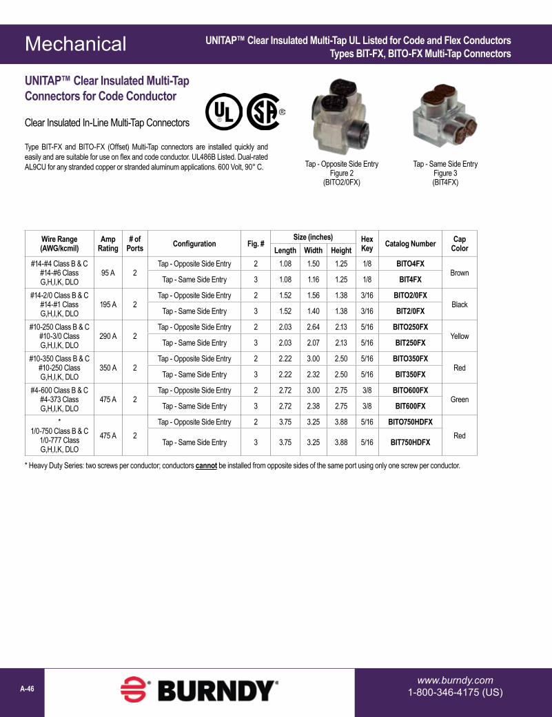
Mechanical
www.burndy.com1-800-346-4175 (US)A-46
UNITAP™ Clear Insulated Multi-Tap UL Listed for Code and Flex ConductorsTypes BIT-FX, BITO-FX Multi-Tap Connectors
Wire Range(AWG/kcmil)
AmpRating
# of Ports Configuration Fig. #
Size (inches) Hex Key Catalog Number Cap
ColorLength Width Height#14-#4 Class B & C
#14-#6 Class G,H,I,K, DLO
95 A 2Tap - Opposite Side Entry 2 1.08 1.50 1.25 1/8 BITO4FX
BrownTap - Same Side Entry 3 1.08 1.16 1.25 1/8 BIT4FX
#14-2/0 Class B & C #14-#1 Class G,H,I,K, DLO
195 A 2Tap - Opposite Side Entry 2 1.52 1.56 1.38 3/16 BITO2/0FX
BlackTap - Same Side Entry 3 1.52 1.40 1.38 3/16 BIT2/0FX
#10-250 Class B & C #10-3/0 Class G,H,I,K, DLO
290 A 2Tap - Opposite Side Entry 2 2.03 2.64 2.13 5/16 BITO250FX
YellowTap - Same Side Entry 3 2.03 2.07 2.13 5/16 BIT250FX
#10-350 Class B & C #10-250 Class G,H,I,K, DLO
350 A 2Tap - Opposite Side Entry 2 2.22 3.00 2.50 5/16 BITO350FX
RedTap - Same Side Entry 3 2.22 2.32 2.50 5/16 BIT350FX
#4-600 Class B & C #4-373 Class G,H,I,K, DLO
475 A 2Tap - Opposite Side Entry 2 2.72 3.00 2.75 3/8 BITO600FX
GreenTap - Same Side Entry 3 2.72 2.38 2.75 3/8 BIT600FX
* 1/0-750 Class B & C
1/0-777 Class G,H,I,K, DLO
475 A 2Tap - Opposite Side Entry 2 3.75 3.25 3.88 5/16 BITO750HDFX
RedTap - Same Side Entry 3 3.75 3.25 3.88 5/16 BIT750HDFX
UNITAP™ Clear Insulated Multi-TapConnectors for Code Conductor
Clear Insulated In-Line Multi-Tap Connectors
Type BIT-FX and BITO-FX (Offset) Multi-Tap connectors are installed quickly and easily and are suitable for use on flex and code conductor. UL486B Listed. Dual-rated AL9CU for any stranded copper or stranded aluminum applications. 600 Volt, 90° C. Tap - Opposite Side Entry
Figure 2(BITO2/0FX)
Tap - Same Side EntryFigure 3(BIT4FX)
* Heavy Duty Series: two screws per conductor; conductors cannot be installed from opposite sides of the same port using only one screw per conductor.

Mechanical
1-800-465-7051 (Canada)1-603-647-5299 (International) A-47
UNITAP™ Clear Insulated Connectors UL Listed for Code and Flex ConductorsType BIBS-FX, Multi-Port, Single-Sided Entry Connectors
UNITAP™ Clear Insulated Multi-Port Connectors for Code and Flex Conductor; Single-Sided Entry
Clear Insulated Multi-Port Connectors
Type BIBS-FX Multi-Port, Single-Sided Tap connectors for quick, easy tap connections for code and flex conductor. UL486B Listed. Dual-rated AL9CU for any stranded copper or stranded aluminum applications. 600 Volt, 90° C. The UNITAP™ line for code and flex conductor features color-coordinated conductor port caps that display the wire range and classes of conductor accepted by the specific connector. The screw port caps show the installation torque information for quick and easy reference during installation.
Wire Range(AWG/kcmil)
AmpRating
# of Ports Configuration Fig. #
Size (inches) Hex Key Catalog Number Cap
ColorLength Width Height
#14-#4 Class B & C #14-#6 Class G,H,I,K, DLO
95 A
3 Single Sided Entry 4 1.51 1.16 1.25 1/8 BIBS43FX
Brown4 Single Sided Entry 4 1.95 1.16 1.25 1/8 BIBS44FX5 Single Sided Entry 4 2.39 1.16 1.25 1/8 BIBS45FX6 Single Sided Entry 4 2.83 1.16 1.25 1/8 BIBS46FX8 Single Sided Entry 4 3.71 1.16 1.25 1/8 BIBS48FX
#14-2/0 Class B & C #14-#1 Class G,H,I,K, DLO
195 A
3 Single Sided Entry 4 2.19 1.31 1.38 3/16 BIBS2/03FX
Black
4 Single Sided Entry 4 2.86 1.31 1.38 3/16 BIBS2/04FX5 Single Sided Entry 4 3.53 1.31 1.38 3/16 BIBS2/05FX6 Single Sided Entry 4 4.20 1.31 1.38 3/16 BIBS2/06FX8 Single Sided Entry 4 5.55 1.31 1.38 3/16 BIBS2/08FX10 Single Sided Entry 4 6.89 1.31 1.38 3/16 BIBS2/010FX12 Single Sided Entry 4 8.24 1.31 1.38 3/16 BIBS2/012FX14 Single Sided Entry 4 9.58 1.31 1.38 3/16 BIBS2/014FX
#10-250 Class B & C #10-3/0 Class G,H,I,K, DLO
290 A
3 Single Sided Entry 4 2.97 2.07 2.13 5/16 BIBS2503FX
Yellow
4 Single Sided Entry 4 3.91 2.07 2.13 5/16 BIBS2504FX5 Single Sided Entry 4 4.84 2.07 2.13 5/16 BIBS2505FX6 Single Sided Entry 4 5.78 2.07 2.13 5/16 BIBS2506FX8 Single Sided Entry 4 7.66 2.07 2.13 5/16 BIBS2508FX10 Single Sided Entry 4 9.53 2.07 2.13 5/16 BIBS25010FX12 Single Sided Entry 4 11.41 2.07 2.13 5/16 BIBS25012FX14 Single Sided Entry 4 13.29 2.07 2.13 5/16 BIBS25014FX
#10-350 Class B & C #10-250 Class G,H,I,K, DLO
350 A
3 Single Sided Entry 4 3.13 2.32 2.50 5/16 BIBS3503FX
Red
4 Single Sided Entry 4 4.04 2.32 2.50 5/16 BIBS3504FX5 Single Sided Entry 4 4.95 2.32 2.50 5/16 BIBS3505FX6 Single Sided Entry 4 5.86 2.32 2.50 5/16 BIBS3506FX8 Single Sided Entry 4 7.68 2.32 2.50 5/16 BIBS3508FX10 Single Sided Entry 4 9.50 2.32 2.50 5/16 BIBS35010FX12 Single Sided Entry 4 11.32 2.32 2.50 5/16 BIBS35012FX14 Single Sided Entry 4 13.14 2.32 2.50 5/16 BIBS35014FX
Multiple Port Tap Single Sided EntryFigure 4
(BIBS2/03FX)

Mechanical
www.burndy.com1-800-346-4175 (US)A-48
UNITAP™ Clear Insulated Connectors UL Listed for Code and Flex ConductorsType BIBS-FX, Multi-Port, Single-Sided Entry Connectors
Wire Range(AWG/kcmil)
AmpRating
# of Ports Configuration Fig. #
Size (inches) Hex Key Catalog Number Cap
ColorLength Width Height
#4-600 Class B & C #4-373 Class G,H,I,K, DLO
475 A
3 Single Sided Entry 4 4.00 2.38 2.75 3/8 BIBS6003FX
Green
4 Single Sided Entry 4 5.28 2.38 2.75 3/8 BIBS6004FX5 Single Sided Entry 4 6.56 2.38 2.75 3/8 BIBS6005FX6 Single Sided Entry 4 7.84 2.38 2.75 3/8 BIBS6006FX8 Single Sided Entry 4 10.41 2.38 2.75 3/8 BIBS6008FX10 Single Sided Entry 4 12.97 2.38 2.75 3/8 BIBS60010FX12 Single Sided Entry 4 15.53 2.38 2.75 3/8 BIBS60012FX14 Single Sided Entry 4 18.09 2.38 2.75 3/8 BIBS60014FX
* 1/0-750 Class B & C
1/0-777 Class G,H,I,K, DLO
475 A
3 Single Sided Entry 4 5.50 3.25 3.88 5/16 BIBS7503HDFX
Red
4 Single Sided Entry 4 7.25 3.25 3.88 5/16 BIBS7504HDFX6 Single Sided Entry 4 10.75 3.25 3.88 5/16 BIBS7506HDFX8 Single Sided Entry 4 14.25 3.25 3.88 5/16 BIBS7508HDFX10 Single Sided Entry 4 17.75 3.25 3.88 5/16 BIBS75010HDFX12 Single Sided Entry 4 21.25 3.25 3.88 5/16 BIBS75012HDFX14 Single Sided Entry 4 24.75 3.25 3.88 5/16 BIBS75014HDFX
UNITAP™ (Continued)
* Heavy Duty Series: two screws per conductor; conductors cannot be installed from opposite sides of the same port using only one screw per conductor.

Mechanical
1-800-465-7051 (Canada)1-603-647-5299 (International) A-49
Multiple Port Tap Double Sided EntryFigure 5
(BIBD2503FX)
UNITAP™ Clear Insulated Connectors UL Listed for Code and Flex ConductorsType BIBD-FX, Multi-Port, Double-Sided Entry Connectors
UNITAP™ Clear Insulated Multi-Port Connectors for Code and Flex Conductor; Double-Sided Entry
Clear Insulated Multi-Port Connectors
Type BIBD-FX Multi-Port, Double-Sided Tap connectors for quick, easy tap connections for code and flex conductor. UL486B Listed. Dual-rated AL9CU for any stranded copper or stranded aluminum applications. 600 Volt, 90° C. The UNITAP™ line for code and flex conductor features color-coordinated conductor port caps that display the wire range and classes of conductor accepted by the specific connector. The screw port caps show the installation torque information for quick and easy reference during installation.
Wire Range(AWG/kcmil)
AmpRating
# of Ports Configuration Fig. #
Size (inches) Hex Key Catalog Number Cap
ColorLength Width Height
#14-#4 Class B & C #14-#6 Class G,H,I,K, DLO
95 A
2 Double Sided Entry 5 1.08 1.50 1.25 1/8 BIBD42FX
Brown
3 Double Sided Entry 5 1.51 1.50 1.25 1/8 BIBD43FX4 Double Sided Entry 5 1.95 1.50 1.25 1/8 BIBD44FX5 Double Sided Entry 5 2.39 1.50 1.25 1/8 BIBD45FX6 Double Sided Entry 5 2.83 1.50 1.25 1/8 BIBD46FX8 Double Sided Entry 5 3.71 1.50 1.25 1/8 BIBD48FX
#10-250 Class B & C #10-3/0 Class G,H,I,K, DLO
290 A
2 Double Sided Entry 5 2.03 2.64 2.13 5/16 BIBD2502FX
Yellow
3 Double Sided Entry 5 2.97 2.64 2.13 5/16 BIBD2503FX4 Double Sided Entry 5 3.91 2.64 2.13 5/16 BIBD2504FX5 Double Sided Entry 5 4.84 2.64 2.13 5/16 BIBD2505FX6 Double Sided Entry 5 5.78 2.64 2.13 5/16 BIBD2506FX8 Double Sided Entry 5 7.66 2.64 2.13 5/16 BIBD2508FX10 Double Sided Entry 5 9.53 2.64 2.13 5/16 BIBD25010FX12 Double Sided Entry 5 11.41 2.64 2.13 5/16 BIBD25012FX14 Double Sided Entry 5 13.29 2.64 2.13 5/16 BIBD25014FX
#10-350 Class B & C #10-250 Class G,H,I,K, DLO
350 A
2 Double Sided Entry 5 3.13 3.00 2.50 5/16 BIBD3502FX
Red
3 Double Sided Entry 5 4.04 3.00 2.50 5/16 BIBD3503FX4 Double Sided Entry 5 4.95 3.00 2.50 5/16 BIBD3504FX5 Double Sided Entry 5 5.86 3.00 2.50 5/16 BIBD3505FX6 Double Sided Entry 5 7.68 3.00 2.50 5/16 BIBD3506FX8 Double Sided Entry 5 9.50 3.00 2.50 5/16 BIBD3508FX10 Double Sided Entry 5 11.32 3.00 2.50 5/16 BIBD35010FX12 Double Sided Entry 5 13.14 3.00 2.50 5/16 BIBD35012FX

Mechanical
www.burndy.com1-800-346-4175 (US)A-50
UNITAP™ Clear Insulated Connectors UL Listed for Code and Flex ConductorsType BIBD-FX, Multi-Port, Double-Sided Entry Connectors
UNITAP™ (Continued)
Wire Range(AWG/kcmil)
AmpRating
# of Ports Configuration Fig. #
Size (inches) Hex Key Catalog Number Cap
ColorLength Width Height
#4-600 Class B & C #4-373 Class G,H,I,K, DLO
475 A
2 Double Sided Entry 5 2.72 3.00 2.75 3/8 BIBD6002FX
Green
3 Double Sided Entry 5 4.00 3.00 2.75 3/8 BIBD6003FX4 Double Sided Entry 5 5.28 3.00 2.75 3/8 BIBD6004FX5 Double Sided Entry 5 6.56 3.00 2.75 3/8 BIBD6005FX6 Double Sided Entry 5 7.84 3.00 2.75 3/8 BIBD6006FX8 Double Sided Entry 5 10.41 3.00 2.75 3/8 BIBD6008FX10 Double Sided Entry 5 12.97 3.00 2.75 3/8 BIBD60010FX12 Double Sided Entry 5 15.53 3.00 2.75 3/8 BIBD60012FX14 Double Sided Entry 5 18.09 3.00 2.75 3/8 BIBD60014FX
* 1/0-750
Class B & C 1/0-777 Class G,H,I,K, DLO
475 A
2 Double Sided Entry 5 3.75 3.25 3.88 5/16 BIBD7502HDFX
Red
3 Double Sided Entry 5 5.50 3.25 3.88 5/16 BIBD7503HDFX4 Double Sided Entry 5 7.25 3.25 3.88 5/16 BIBD7504HDFX6 Double Sided Entry 5 10.75 3.25 3.88 5/16 BIBD7506HDFX8 Double Sided Entry 5 14.25 3.25 3.88 5/16 BIBD7508HDFX10 Double Sided Entry 5 17.75 3.25 3.88 5/16 BIBD75010HDFX12 Double Sided Entry 5 21.25 3.25 3.88 5/16 BIBD75012HDFX14 Double Sided Entry 5 24.75 3.25 3.88 5/16 BIBD75014HDFX
* Heavy Duty Series: two screws per conductor; conductors cannot be installed from opposite sides of the same port using only one screw per conductor.

Mechanical
1-800-465-7051 (Canada)1-603-647-5299 (International) A-51
UNITAP™ Clear Insulated Connectors UL Listed for Code and Flex ConductorType BIBS-FXMT; Mountable, Multi-Port, Single-Sided Entry Connectors
Wire Range(AWG/kcmil)
AmpRating
# of Ports Configuration Fig. #
Size (inches) Hex Key Catalog Number Cap
ColorLength Width Height
#14-2/0 Class B & C #14-#1 Class G,H,I,K, DLO
195 A
4 Mountable Single Sided Entry 6 4.20 1.25 1.50 3/16 BIBS2/04FXMT
Black6 Mountable Single Sided Entry 6 5.55 1.25 1.50 3/16 BIBS2/06FXMT8 Mountable Single Sided Entry 6 6.89 1.25 1.50 3/16 BIBS2/08FXMT10 Mountable Single Sided Entry 6 8.24 1.25 1.50 3/16 BIBS2/010FXMT12 Mountable Single Sided Entry 6 9.58 1.25 1.50 3/16 BIBS2/012FXMT
#10-250 Class B & C #10-3/0 Class G,H,I,K, DLO
290 A
4 Mountable Single Sided Entry 6 5.78 1.95 2.63 5/16 BIBS2504FXMT
Yellow6 Mountable Single Sided Entry 6 7.65 1.95 2.63 5/16 BIBS2506FXMT8 Mountable Single Sided Entry 6 9.53 1.95 2.63 5/16 BIBS2508FXMT10 Mountable Single Sided Entry 6 11.41 1.95 2.63 5/16 BIBS25010FXMT12 Mountable Single Sided Entry 6 13.29 1.95 2.63 5/16 BIBS25012FXMT
#10-350 Class B & C #10-250 Class G,H,I,K, DLO
350 A
4 Mountable Single Sided Entry 6 5.86 2.32 2.63 5/16 BIBS3504FXMT
Red6 Mountable Single Sided Entry 6 7.68 2.32 2.63 5/16 BIBS3506FXMT8 Mountable Single Sided Entry 6 9.50 2.32 2.63 5/16 BIBS3508FXMT10 Mountable Single Sided Entry 6 11.32 2.32 2.63 5/16 BIBS35010FXMT12 Mountable Single Sided Entry 6 13.14 2.32 2.63 5/16 BIBS35012FXMT
#4-600 Class B & C #4-373 Class G,H,I,K, DLO
475 A
4 Mountable Single Sided Entry 6 5.53 2.25 2.88 3/8 BIBS6004FXMT
Green6 Mountable Single Sided Entry 6 7.40 2.25 2.88 3/8 BIBS6006FXMT8 Mountable Single Sided Entry 6 9.28 2.25 2.88 3/8 BIBS6008FXMT12 Mountable Single Sided Entry 6 13.03 2.25 2.88 3/8 BIBS60012FXMT
UNITAP™ Clear Insulated Multi-Port Connectorsfor Code and Flex Conductor; Mountable; Single-Sided Entry
Clear Insulated Multiple Tap Connectors
Type BIBS-FXMT Multi-Port, Single-Sided Tap connectors offer the same features as the standard Type BIBS-FX UNITAP™ connectors except these -FXMT types are provided with two isolated mounting holes, one at each side of the connector for direct mounting to trough, gutter, or wireway. They will accommodate up to standard 1/4” hardware. UL486B Listed. Dual-rated AL9CU for any stranded copper or stranded aluminum applications. 600 Volt, 90° C.
Multiple Port Mounted TapSingle Sided Entry
Figure 6(BIBS2504FXMT)

Mechanical
www.burndy.com1-800-346-4175 (US)A-52
UNITAP™ Clear Insulated Connectors UL Listed for Code and Flex ConductorType BIBD-FXMT, Mountable, Multi-Port, Double-Sided Entry Connectors
UNITAP™ Clear Insulated Multi-Port Connectorsfor Code and Flex Conductor; Mountable; Double-Sided Entry
Clear Insulated Multiple Tap Connectors
Type BIBD-FXMT Multi-Port, Double-Sided Tap connectors offer the same features as the standard Type BIBD-FX UNITAP™ connectors except these -FXMT types are provided with two isolated mounting holes, one at each side of the connector for direct mounting to trough, gutter, or wireway. They will accommodate up to standard 1/4” hardware. UL486B Listed. Dual-rated AL9CU for any stranded copper or stranded aluminum applications. 600 Volt, 90° C.
Multiple Port Mounted TapDouble Sided Entry
Figure 7(BIBD6004FXMT)
Wire Range(AWG/kcmil)
AmpRating
# of Ports Configuration Fig.
#Size (inches) Hex
Key Catalog Number Cap ColorLength Width Height
#14-2/0 Class B & C #14-#1 Class G,H,I,K, DLO
195 A
4 Mountable Double Sided Entry 7 4.20 1.56 1.50 3/16 BIBD2/04FXMT
Black8 Mountable Double Sided Entry 7 6.89 1.56 1.50 3/16 BIBD2/08FXMT10 Mountable Double Sided Entry 7 8.24 1.56 1.50 3/16 BIBD2/010FXMT12 Mountable Double Sided Entry 7 9.58 1.56 1.50 3/16 BIBD2/012FXMT4 Mountable Double Sided Entry 7 5.78 2.64 2.63 5/16 BIBD2504FXMT
#10-250 Class B & C #10-3/0 Class G,H,I,K, DLO
290 A
6 Mountable Double Sided Entry 7 7.65 2.64 2.63 5/16 BIBSD506FXMT
Yellow8 Mountable Double Sided Entry 7 9.53 2.64 2.63 5/16 BIBD2508FXMT10 Mountable Double Sided Entry 7 11.41 2.64 2.63 5/16 BIBD25010FXMT12 Mountable Double Sided Entry 7 13.29 2.64 2.63 5/16 BIBD25012FXMT4 Mountable Double Sided Entry 7 5.86 3.00 2.63 5/16 BIBD3504FXMT
#10-350 Class B & C #10-250 Class G,H,I,K, DLO
350 A
6 Mountable Double Sided Entry 7 7.68 3.00 2.63 5/16 BIBD3506FXMT
Red8 Mountable Double Sided Entry 7 9.50 3.00 2.63 5/16 BIBD3508FXMT10 Mountable Double Sided Entry 7 11.32 3.00 2.63 5/16 BIBD35010FXMT12 Mountable Double Sided Entry 7 13.14 3.00 2.63 5/16 BIBD35012FXMT4 Mountable Double Sided Entry 7 5.53 3.00 2.88 3/8 BIBD6004FXMT
#4-600 Class B & C #4-373 Class G,H,I,K, DLO
475 A
6 Mountable Double Sided Entry 7 7.40 3.00 2.88 3/8 BIBD6006FXMT
Green8 Mountable Double Sided Entry 7 9.28 3.00 2.88 3/8 BIBD6008FXMT10 Mountable Double Sided Entry 7 11.16 3.00 2.88 3/8 BIBD60010FXMT12 Mountable Double Sided Entry 7 13.03 3.00 2.88 3/8 BIBD60012FXMT

Mechanical
1-800-465-7051 (Canada)1-603-647-5299 (International) A-53
UV Rated Black UNITAP™
UNITAP™
UV Rated Black Insulated Multiple Tap Connectors and Splice Reducers
Tap connections are made quickly and easily with the UNITAP™ line of connectors. UL486A-B Listed. Dual-rated for any stranded copper or stranded aluminum applications. UL Listed 600 Volts, -40° C to 135° C Operating Temperature.
UNITAP™ UV Rated Black Insulated Multiple Tap ConnectorsFor Class B & C Conductors Only
Features & Benefits• UV Rated covering over AL6061-T6 aluminum body saves
time, lowering installation costs and elimates taping• Oxide inhibitor pre-installed inhibits moisture and
contaminants from entering the contact area• Range-taking capability reduces the number of connectors
necessary to carry in inventory• AL486B Listed, AL9CU, 600 Volts, 90°C• Operating temperature -40°C to 135°C
Figure 1
Figure 2
Figure 3
Figure 4
Figure 5
In-Line Splice Reducer(1PBS1/0)
Tap - Opposite Side Entry
(1PLO2502)
Tap - Same Side Entry(1PL42)
Multiple Port TapSingle Sided Entry
(1PL2503)
Multiple Port TapDouble Sided Entry
(1PLD2504)
Figure 6
Multiple Port TapDouble Sided Entry
Heavy Duty 750 Series(1PLD7504HD)
Wire Range(AWG/kcmil)
CLASS B & C ONLY# of
Ports Configuration Fig. #Size (inches) Hex
Key Catalog Number InstallationTorque (in-lbs)Length Width Height
14 AWG-2 AWG
2 In-Line Splice Reducer 1
2.38 0.75 1.22 5/32 1PBS2 4514 AWG-1/0 AWG 2.91 0.91 1.38 3/16 1PBS1/0 12010 AWG-250 kcmil 4.01 1.19 2.10 5/16 1PBS250 27510 AWG-350 kcmil 4.63 1.34 2.35 5/16 1PBS350 2756 AWG-500 kcmil 5.00 1.62 2.62 3/8 1PBS500 375
* #2 AWG - 750 kcmil 10.53 1.88 3.01 3/8” 1PBS750HD 50014 AWG-4 AWG
2 Tap - Opposite Side Entry 2
1.08 1.50 1.25 1/8 1PLO42 4514 AWG-2/0 AWG 1.52 1.56 1.38 3/16 1PLO2/02 12010 AWG-250 kcmil 2.03 2.64 2.13 5/16 1PLO2502 27510 AWG-350 kcmil 2.22 3.00 2.5 5/16 1PLO3502 2754 AWG-600 kcmil 2.72 3.00 2.75 3/8 1PLO6002 37514 AWG-4 AWG
2 Tap - Same Side Entry 3
1.08 1.16 1.25 1/8 1PL42 4514 AWG-2/0 AWG 1.52 1.40 1.38 3/16 1PL2/02 12010 AWG-250 kcmil 2.03 2.07 2.13 5/16 1PL2502 27510 AWG-350 kcmil 2.22 2.32 2.5 5/16 1PL3502 2754 AWG-600 kcmil 2.72 2.38 2.75 3/8 1PL6002 375
14 AWG-4 AWG3
Single Sided Entry 4
1.51 1.25 1.25 1/8 1PL4345
4 1.95 1.25 1.25 1/8 1PL4414 AWG-2/0 AWG 3 2.19 1.31 1.38 3/16 1PL2/03 12010 AWG-250 kcmil 3 2.97 2.07 2.13 5/16 1PL2503 275
* Heavy Duty Series: two screws per conductor; conductors cannot be installed from opposite sides of the same port using only one screw per conductor.

Mechanical
www.burndy.com1-800-346-4175 (US)A-54
UNITAP™ UV Rated Black Insulated Multiple Tap ConnectorsFor Class B & C Conductors Only
UV Rated Black UNITAP™ (Continued)
* Heavy Duty Series: two screws per conductor; conductors cannot be installed from opposite sides of the same port using only one screw per conductor.
Wire Range(AWG/kcmil)
CLASS B & C ONLY# of
Ports Configuration Fig. #Size (inches) Hex
Key Catalog Number InstallationTorque (in-lbs)Length Width Height
14 AWG-4 AWG3
Double Sided Entry 5
1.51 1.50 1.25 1/8 1PLD4345
4 1.95 1.50 1.25 1/8 1PLD44
14 AWG-2/0 AWG
2 1.52 1.56 1.38 3/16 1PLD2/02
1203 2.19 1.56 1.38 3/16 1PLD2/034 2.86 1.56 1.38 3/16 1PLD2/046 4.2 1.56 1.38 3/16 1PLD2/06
10 AWG-250 kcmil
2 2.03 2.64 2.13 5/16 1PLD2502
2753 2.97 2.64 2.13 5/16 1PLD25034 3.91 2.64 2.13 5/16 1PLD25046 5.78 2.64 2.13 5/16 1PLD2506
10 AWG-350 kcmil
2 2.22 3.00 2.5 5/16 1PLD3502
2753 3.13 3.00 2.5 5/16 1PLD35034 4.04 3.00 2.5 5/16 1PLD35046 5.86 3.00 2.5 5/16 1PLD35068 7.68 3.00 2.5 5/16 1PLD3508
4 AWG-600 kcmil
2 2.72 3.00 2.75 3/8 1PLD6002
375
3 4.00 3.00 2.75 3/8 1PLD60034 5.28 3.00 2.75 3/8 1PLD60045 6.56 3.00 2.75 3/8 1PLD60056 7.84 3.00 2.75 3/8 1PLD60068 10.40 3.00 2.75 3/8 1PLD6008
* #2 AWG - 750 kcmil
2
Double Sided Entry 6
2.63 4.83 3.00 3/8” 1PLD7502HD
500
3 4.00 4.83 3.00 3/8” 1PLD7503HD4 5.38 4.83 3.00 3/8” 1PLD7504HD5 6.75 4.83 3.00 3/8” 1PLD7505HD6 8.13 4.83 3.00 3/8” 1PLD7506HD8 10.88 4.83 3.00 3/8” 1PLD7508HD
10 13.63 4.83 3.00 3/8” 1PLD75010HD12 16.38 4.83 3.00 3/8” 1PLD75012HD

Mechanical
1-800-465-7051 (Canada)1-603-647-5299 (International) A-55
VERSIPOLE™ Configurable Power Distribution Blocks for Copper and Aluminum
Figure 1Open Style
BDBMCS5M1 shown
Figure 2 Finger-Safe Style comes with covers and end plates
BDBMCS5M1FS shown
Figure 3Finger-Safe Kits include
only covers and end plates
Ordering Information & Footnotes:Finger-Safe Kits include translucent top cover and end plates only. Order 1 kit per pole. The kits are used in conjunction with Open style distribution blocks. (Distribution blocks are not included.)
† To achieve Finger-Safe style Adder order Open style Adder and Finger-Safe Kit
Optional Hinged Covers are available for use with Open style blocks and are ordered 1 cover per pole.
Optional Hinged Covers:Catalog Number Size
BDBSCSCOVER Small
BDBMCSCOVER MediumBDBLCSCOVER Large
VERSIPOLE™
UL Listed 1953; Finger-Safe IEC 60527; IP-20 Rating
The VERSIPOLE™ Configurable Series Power Distribution Blocks are used for splicing and distributing power from primary run(s) to secondary/branch circuits. They are offered in standard one, two, or three pole configurations. The configurable series can also be designed to accommodate an infinite number of made-to-order combinations.
Features & Benefits• 600 Volt rated; Listed to UL1953; Rated for use with both code and flex
conductor without requiring ferrules• AL9CU dual rated for use with copper and aluminum conductors• Range taking designs accommodate wire sizes up to 535 DLO and can
support 1 or 2 run conductors and up to 12 taps for secondary circuits• Allow for panel mounting; medium and large sizes also allow for DIN rail
mounting• Finger-Safe style are provided with translucent polycarbonate top covers
and end plates to permit easy visual inspection and provide IEC 60529 IP-20 Rating
• High Short-Circuit Current rating up to 100kA with proper fusing• Bases and side barriers of glass-reinforced nylon 6/6 for extra durability and
excellent insulating properties; carry a UL94 flammability rating of V0
Small Series:Catalog Number # of Conductors Wire Range
(Class B, C, H, I, K, DLO) # of Poles
DimensionsAmp Rating
per PoleOpen Style (Fig. 1)
Finger-Safe Style (Fig. 2) Finger-Safe Kit (Fig. 3) Run Tap Run Tap W D H
BDBSCS1C1 BDBSCS1C1FS
BDBSCS1C1FSKIT 1 4 #14 - 2/0 #14 - #4
1 1.34 3.06 3.59 175
BDBSCS1C2 BDBSCS1C2FS 2 2.41 3.06 3.59 175
BDBSCS1C3 BDBSCS1C3FS 3 3.48 3.06 3.59 175
BDBSCS1CA † Adder 1.16 3.06 3.59 175
BDBLCS3A1FS shown BDBLCS3A2FS shown

Mechanical
www.burndy.com1-800-346-4175 (US)A-56
VERSIPOLE™ (Continued)
VERSIPOLE™ Configurable Power Distribution Blocks for Copper and Aluminum
Small Series: (continued)Catalog Number # of Conductors Wire Range
(Class B, C, H, I, K, DLO) # of Poles
DimensionsAmp Rating
per PoleOpen Style (Fig. 1)
Finger-Safe Style (Fig. 2) Finger-Safe Kit (Fig. 3) Run Tap Run Tap W D H
BDBSCS1P1 BDBSCS1P1FS
BDBSCS1P1FSKIT 1 1 #14 - 2/0 #14 - 2/0
1 1.34 3.06 3.59 175
BDBSCS1P2 BDBSCS1P2FS 2 2.41 3.06 3.59 175
BDBSCS1P3 BDBSCS1P3FS 3 3.48 3.06 3.59 175
BDBSCS1PA † Adder 1.16 3.06 3.59 175
Medium Series:BDBMCS1F1 BDBMCS1F1FS
BDBMCS1F1FSKIT 1 6 #14 - 2/0 #14 - #2
1 2.09 4.52 3.70 175
BDBMCS1F2 BDBMCS1F2FS 2 3.90 4.52 3.70 175
BDBMCS1F3 BDBMCS1F3FS 3 5.72 4.52 3.70 175
BDBMCS1FA † Adder 1.91 4.52 3.70 175
BDBMCS3U1 BDBMCS3U1FS
BDBMCS3U1FSKIT 1 1 #6 - 350 #6 - 350
1 2.09 4.52 3.70 310
BDBMCS3U2 BDBMCS3U2FS 2 3.90 4.52 3.70 310
BDBMCS3U3 BDBMCS3U3FS 3 5.72 4.52 3.70 310
BDBMCS3UA † Adder 1.91 4.52 3.70 310
BDBMCS2F1 BDBMCS2F1FS
BDBMCS2F1FSKIT 2 6 #14 - 2/0 #14 - #2
1 2.09 4.52 3.70 350
BDBMCS2F2 BDBMCS2F2FS 2 3.90 4.52 3.70 350
BDBMCS2F3 BDBMCS2F3FS 3 5.72 4.52 3.70 350
BDBMCS2FA † Adder 1.91 4.52 3.70 350
BDBMCS2N1 BDBMCS2N1FS
BDBMCS2N1FSKIT 2 2 #14 - 2/0 #14 - 2/0
1 2.09 4.52 3.70 350
BDBMCS2N2 BDBMCS2N2FS 2 3.90 4.52 3.70 350
BDBMCS2N3 BDBMCS2N3FS 3 5.72 4.52 3.70 350
BDBMCS2NA † Adder 1.91 4.52 3.70 350
BDBMCS5F1 BDBMCS5F1FS
BDBMCS5F1FSKIT 1 6 #4 - 500 #14 - #2
1 2.09 4.52 3.70 380
BDBMCS5F2 BDBMCS5F2FS 2 3.90 4.52 3.70 380
BDBMCS5F3 BDBMCS5F3FS 3 5.72 4.52 3.70 380
BDBMCS5FA † Adder 1.91 4.52 3.70 380
BDBMCS5M1 BDBMCS5M1FS
BDBMCS5M1FSKIT 1 4 #4 - 500 #14 - 2/0
1 2.09 4.52 3.70 380
BDBMCS5M2 BDBMCS5M2FS 2 3.90 4.52 3.70 380
BDBMCS5M3 BDBMCS5M3FS 3 5.72 4.52 3.70 380
BDBMCS5MA † Adder 1.91 4.52 3.70 380
Large Series:BDBLCS3A1 BDBLCS3A1FS
BDBLCS3A1FSKIT 1 12 #6 - 350 #14 - #4
1 3.25 5.54 4.12 310
BDBLCS3A2 BDBLCS3A2FS 2 6.17 5.54 4.12 310
BDBLCS3A3 BDBLCS3A3FS 3 9.09 5.54 4.12 310
BDBLCS3AA † Adder 3.05 5.54 4.12 310
BDBLCS3K1 BDBLCS3K1FS
BDBLCS3K1FSKIT 1 6 #6 - 350 #14 - 2/0
1 3.25 5.54 4.12 310
BDBLCS3K2 BDBLCS3K2FS 2 6.17 5.54 4.12 310
BDBLCS3K3 BDBLCS3K3FS 3 9.09 5.54 4.12 310
BDBLCS3KA † Adder 3.05 5.54 4.12 310

Mechanical
1-800-465-7051 (Canada)1-603-647-5299 (International) A-57
VERSIPOLE™ Configurable Power Distribution Blocks for Copper and Aluminum
VERSIPOLE™ (Continued)
Large Series: (continued)Catalog Number # of Conductors Wire Range
(Class B, C, H, I, K, DLO) # of Poles
DimensionsAmp Rating per
PoleOpen Style (Fig. 1)
Finger-Safe Style (Fig. 2) Finger-Safe Kit (Fig. 3) Run Tap Run Tap W D H
BDBLCS5K1 BDBLCS5K1FS
BDBLCS5K1FSKIT 1 6 #4 - 500 #14 - 2/0
1 3.25 5.54 4.12 380
BDBLCS5K2 BDBLCS5K2FS 2 6.17 5.54 4.12 380
BDBLCS5K3 BDBLCS5K3FS 3 9.09 5.54 4.12 380
BDBLCS5KA † Adder 3.05 5.54 4.12 380
BDBLCS5W1 BDBLCS5W1FS
BDBLCS5W1FSKIT 1 1 #4 - 500 #4 - 500
1 3.25 5.54 4.12 380
BDBLCS5W2 BDBLCS5W2FS 2 6.17 5.54 4.12 380
BDBLCS5W3 BDBLCS5W3FS 3 9.09 5.54 4.12 380
BDBLCS5WA † Adder 3.05 5.54 4.12 380
BDBLCS4K1 BDBLCS4K1FS
BDBLCS4K1FSKIT 2 6 #6 - 350 #14 - 2/0
1 3.25 5.54 4.12 620
BDBLCS4K2 BDBLCS4K2FS 2 6.17 5.54 4.12 620
BDBLCS4K3 BDBLCS4K3FS 3 9.09 5.54 4.12 620
BDBLCS4KA † Adder 3.05 5.54 4.12 620
BDBLCS4T1 BDBLCS4T1FS
BDBLCS4T1FSKIT 2 2 #6 - 350 #6 - 350
1 3.25 5.54 4.12 620
BDBLCS4T2 BDBLCS4T2FS 2 6.17 5.54 4.12 620
BDBLCS4T3 BDBLCS4T3FS 3 9.09 5.54 4.12 620
BDBLCS4TA † Adder 3.05 5.54 4.12 620
BDBLCS6A1 BDBLCS6A1FS
BDBLCS6A1FSKIT 2 12 #4 - 500 #14 - #4
1 3.25 5.54 4.12 760
BDBLCS6A2 BDBLCS6A2FS 2 6.17 5.54 4.12 760
BDBLCS6A3 BDBLCS6A3FS 3 9.09 5.54 4.12 760
BDBLCS6AA † Adder 3.05 5.54 4.12 760
BDBLCS6K1 BDBLCS6K1FS
BDBLCS6K1FSKIT 2 6 #4 - 500 #14 - 2/0
1 3.25 5.54 4.12 760
BDBLCS6K2 BDBLCS6K2FS 2 6.17 5.54 4.12 760
BDBLCS6K3 BDBLCS6K3FS 3 9.09 5.54 4.12 760
BDBLCS6KA † Adder 3.05 5.54 4.12 760
BDBLCS6R1 BDBLCS6R1FS
BDBLCS6R1FSKIT 2 4 #4 - 500 #6 - 4/0
1 3.25 5.54 4.12 760
BDBLCS6R2 BDBLCS6R2FS 2 6.17 5.54 4.12 760
BDBLCS6R3 BDBLCS6R3FS 3 9.09 5.54 4.12 760
BDBLCS6RA † Adder 3.05 5.54 4.12 760
BDBLCS6V1 BDBLCS6V1FS
BDBLCS6V1FSKIT 2 2 #4 - 500 #4 - 500
1 3.25 5.54 4.12 760
BDBLCS6V2 BDBLCS6V2FS 2 6.17 5.54 4.12 760
BDBLCS6V3 BDBLCS6V3FS 3 9.09 5.54 4.12 760
BDBLCS6VA † Adder 3.05 5.54 4.12 760
BDBLCS8Y1 BDBLCS8Y1FS
— 2 2#4 - 600
(Class B & C only)
#4 - 600(Class B &
C only)
1 3.25 5.54 4.12 840
BDBLCS8Y2 BDBLCS8Y2FS 2 6.17 5.54 4.12 840
BDBLCS8Y3 BDBLCS8Y3FS 3 9.09 5.54 4.12 840
BDBLCS8YA — Adder 3.05 5.54 4.12 840
† To achieve Finger-Safe style Adder order Open style Adder and Finger-Safe Kit

Mechanical
www.burndy.com1-800-346-4175 (US)A-58
VERSIPOLE™ Configurable Power Distribution Blocks for Copper and Aluminum
Double-WideBDBLCS7X1DW shown
Box-to-StudBDBLCS5SK1 shown
Stud-to-StudBDBLCS5S5S1 shown
Features & Benefits• 600 Volt Rated• Listed to UL1953• Rated for use with code and flex conductor without requiring ferrules• AL9CU dual rated for use with copper and aluminum conductors• Range taking conductor ports can accommodate wire sizes up to 535 DLO
and can support up to 5 run conductors and up to 24 tap conductors• High Short-Circuit Current Rating up to 100kA with proper fusing
VERSIPOLE™
Double-Wide, Box-to-Stud, and Stud-to-Stud Styles
These styles offer additional splicing and tapping options over the standard Open and Finger-Safe styles.

Mechanical
1-800-465-7051 (Canada)1-603-647-5299 (International) A-59
VERSIPOLE™ Configurable Power Distribution Blocks for Copper and Aluminum
VERSIPOLE™ (Continued)
Double-Wide Series:
Catalog Number# of Conductors Wire Range
(Class B, C, H, I, K, DLO) # of Poles
Dimensions Amp Rating
per PoleSCCR1
Run Tap Run Tap W D HBDBLCS7X1DW 5 5 #4 - 500 #4 - 500 1 6.17 5.54 4.12 1720 100kABDBLCS7R1DW 5 8 #4 - 500 #6 - 4/0 1 6.17 5.54 4.12 1456 100kABDBLCS7K1DW 5 12 #4 - 500 #14 - 2/0 1 6.17 5.54 4.12 1170 100kABDBLCS7A1DW 5 24 #4 - 500 #14 - #4 1 6.17 5.54 4.12 1026 100kA
Box-to-Stud and Stud-to-Stud Series:
Catalog Number# of Conductors Wire Range
(Class B, C, H, I, K, DLO) # of Poles
Dimensions Amp Rating
per PoleSCCR1
Run Tap Run Tap W D HBDBSCS1S1S1 1/4” Ø stud 1/4” Ø stud — — 1 1.34 2.76 5.56 175 100kABDBMCS3S3S1 3/8” Ø stud 3/8” Ø stud — — 1 2.09 4.52 3.70 350 100kABDBMCS3SM1 3/8” Ø stud 4 — #14 - 2/0 1 2.09 4.52 3.70 350 100kABDBMCS3SF1 3/8” Ø stud 6 — #14 - #2 1 2.09 4.52 3.70 350 100kABDBLCS5S5S1 1/2” Ø stud 1/2” Ø stud — — 1 3.25 5.54 4.12 620 100kABDBLCS5SK1 1/2” Ø stud 6 — #14 - 2/0 1 3.25 5.54 4.12 380 100kABDBLCS5SA1 1/2” Ø stud 12 — #14 - #4 1 3.25 5.54 4.12 310 100kA
Double-WideBDBLCS7X1DW shown
Box-to-StudBDBLCS5SK1 shown
Stud-to-StudBDBLCS5S5S1 shown
1 Short-Circuit Current Rating with proper fusing
1 Short-Circuit Current Rating with proper fusing
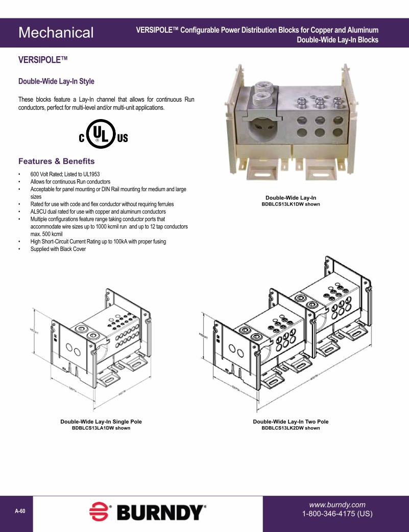
Mechanical
www.burndy.com1-800-346-4175 (US)A-60
VERSIPOLE™ Configurable Power Distribution Blocks for Copper and AluminumDouble-Wide Lay-In Blocks
Double-Wide Lay-InBDBLCS13LK1DW shown
Features & Benefits• 600 Volt Rated; Listed to UL1953• Allows for continuous Run conductors• Acceptable for panel mounting or DIN Rail mounting for medium and large
sizes• Rated for use with code and flex conductor without requiring ferrules• AL9CU dual rated for use with copper and aluminum conductors• Multiple configurations feature range taking conductor ports that
accommodate wire sizes up to 1000 kcmil run and up to 12 tap conductors max. 500 kcmil
• High Short-Circuit Current Rating up to 100kA with proper fusing• Supplied with Black Cover
VERSIPOLE™
Double-Wide Lay-In Style
These blocks feature a Lay-In channel that allows for continuous Run conductors, perfect for multi-level and/or multi-unit applications.
Double-Wide Lay-In Single PoleBDBLCS13LA1DW shown
Double-Wide Lay-In Two PoleBDBLCS13LK2DW shown

Mechanical
1-800-465-7051 (Canada)1-603-647-5299 (International) A-61
VERSIPOLE™ Configurable Power Distribution Blocks for Copper and AluminumDouble-Wide Lay-In Series
VERSIPOLE™ (Continued)
Double-Wide Lay-In Series:
Catalog Number# of Conductors Wire Range
(Class B, C, H, I, K, DLO) # of Poles
Dimensions Amp Rating
per PoleSCCR1
Run Tap Run Tap W D HBDBLCS10LV1DW
1 2 500 - 750 #4 - 5001 6.17 5.54 4.12
475 100kABDBLCS10LV2DW 2 12.00 5.54 4.12BDBLCS10LV3DW 3 17.84 5.54 4.12BDBLCS10LR1DW
1 4 500 - 750 #6 - 4/01 6.17 5.54 4.12
475 100kABDBLCS10LR2DW 2 12.00 5.54 4.12BDBLCS10LR3DW 3 17.84 5.54 4.12BDBLCS10LK1DW
1 6 500 - 750 #14 - 2/01 6.17 5.54 4.12
475 100kABDBLCS10LK2DW 2 12.00 5.54 4.12BDBLCS10LK3DW 3 17.84 5.54 4.12BDBLCS10LA1DW
1 12 500 - 750 #14 - #41 6.17 5.54 4.12
475 100kABDBLCS10LA2DW 2 12.00 5.54 4.12BDBLCS10LA3DW 3 17.84 5.54 4.12BDBLCS13LV1DW
1 2 750 - 1000 #4 - 5001 6.17 5.54 4.12
545 100kABDBLCS13LV2DW 2 12.00 5.54 4.12BDBLCS13LV3DW 3 17.84 5.54 4.12BDBLCS13LR1DW
1 4 750 - 1000 #6 - 4/01 6.17 5.54 4.12
545 100kABDBLCS13LR2DW 2 12.00 5.54 4.12BDBLCS13LR3DW 3 17.84 5.54 4.12BDBLCS13LK1DW
1 6 750 - 1000 #14 - 2/01 6.17 5.54 4.12
545 100kABDBLCS13LK2DW 2 12.00 5.54 4.12BDBLCS13LK3DW 3 17.84 5.54 4.12BDBLCS13LA1DW
1 12 750 - 1000 #14 - #41 6.17 5.54 4.12
545 100kABDBLCS13LA2DW 2 12.00 5.54 4.12BDBLCS13LA3DW 3 17.84 5.54 4.12
Double-Wide Lay-InBDBLCS13LK1DW shown
1 Short-Circuit Current Rating with proper fusing

Mechanical
www.burndy.com1-800-346-4175 (US)A-62
U-BLOK™ Power Distribution Blocks for Junction Box Applications
Catalog Number
Max. Number of Wires per Phase
Conductor Copper or Aluminum* W L H Weight
EachAllen
Wrench Size
Recommended Tightening
TorqueStrip Length
Run TapFT3B4/0 2 3/0 - 4/0 6 - 4/0 3-7/8 5-7/8 4-1/8 1-1/4 1/4 200 1-1/2FT3B500 2 400 - 500 6 - 500 3-7/8 5-7/8 4-1/8 2-1/8 3/8 375 2-5/16
3S 2 250 - 350 6 - 350 3-5/8 9-3/4 4-7/8 3 1/4 200 1-3/4
3U 1 Run / 8 Tap 3/0 - 500 6 - 1/0 4-3/4 9-3/4 5-1/2 3 5/32 110 2-5/16 (Run); 1-5/32 (Tap)
FT4B500
3S
3U
FT3B4/0
Catalog Number
Max. Number of Wires per Phase
Conductor Copper or Aluminum* W L H Weight
EachAllen
Wrench Size
Recommended Tightening
TorqueStrip
LengthRun TapFT4B4/0 2 3/0 - 4/0 6 - 4/0 3-7/8 7-7/8 4-1/8 2 1/4 200 1-1/2FT4B500 2 400 - 500 6 - 500 3-7/8 7-7/8 4-1/8 2-3/4 3/8 375 2-5/16
4S 2 250 - 350 6 - 350 3-5/8 11-3/4 4-7/8 3-1/2 1/4 200 1-3/4
4U 1 Run / 8 Tap 3/0 - 500 6 - 1/0 4-3/4 11-3/4 5-1/2 3-1/2 5/32 110 2-5/16 (Run); 1-5/32 (Tap)
3 WIRE POWER DISTRIBUTION BLOCKS
4 WIRE POWER DISTRIBUTION BLOCKS
PENETROX™ inhibitor is recommended for all aluminum wire connections.For two wire tap range is 8 through 1/0.* Aluminum and copper conductors cannot be assembled under the same pressure plate or t-bar.U-BLOK™ Mounting Platforms for Trough Applications are available, please contact technical services.
POWER DISTRIBUTION BLOCKS
U-BLOK™
For Junction Box Applications
The U-BLOK™ system is a modern, state-of-the-art approach to multi-load power distribution applications. Among typical uses are multi-story or multi-unit buildings, HVAC, refrigeration, control panels, motor control, switch gear, elevator systems and materials handling equipment. U-BLOK™ is UL Listed for Copper or Aluminum conductors and rated for 600-volt applications. U-BLOK™ can be mounted on bases for use in troughs or bolted directly to junction boxes. AL9CU rated.
Features & Benefits• Connector top slides OFF/ON for quick cable lay-in providing labor savings;
easy access for installation, modifications, or retrofit• Electro-tin plated connectors in each pole for durability, high-conductivity and
resistance to corrosion• Compact size requires less space than traditional connection methods• Trough installations can be mounted on raised platforms for passage of
cables under the block, no need for through-cables to be terminated• Insulating covers and mounting blocks are rated 94-V0 savings costly taping,
time, and material; conforms to or exceeds building codes• Connectors accommodate a wide range of wire sizes reducing inventory
requirements• Feeder conductors can be cut or fed through on a continuous run for ease of
installation