
Table of Contents - Zavio Manual_2MP... · Table of Contents 1. Safety Instruction ... Operating...
59
1
Transcript of Table of Contents - Zavio Manual_2MP... · Table of Contents 1. Safety Instruction ... Operating...
1
2
Table of Contents
1 Safety Instruction 4
11 Safety Notice 4
12 Electromagnetic Compatibility (EMC) 5
2 Overview 6
21 2MP Outdoor Motorized Bullet Camera Features and Specifications 6
22 2MP Outdoor Motorized Bullet Camera Package Contents 7
23 Minimum System Requirement 8
3 Web Interface Main Menu 9
4 Setting_Information 13
5 Setting_Basic Setup 14
51 Account 14
52 Network 15
521 TCP IP 15
522 PPPoE 16
53 Date Time 18
54 Video 19
541 Video Setting 20
542 Profile 21
543 DayNight 23
55 Audio 25
6 Setting_Live View 26
61 Video 26
62 Audio 26
63 Camera Setting 27
631 Image Setting 27
632 Lens Settings 29
633 ROI 29
64 PTZ Setting 31
641 Patrol Setting 31
642 PTZ Control 32
7 Setting_Playback 33
71 Client PC 33
72 Network Storage 33
3
73 Edge Storage helliphelliphelliphelliphelliphelliphelliphelliphelliphelliphelliphelliphelliphelliphelliphelliphelliphelliphelliphelliphelliphelliphelliphelliphelliphelliphelliphelliphelliphelliphelliphelliphellip35
8 Setting_Event 36
81 Event Server 36
811 Event Server 36
812 SD Card 38
82 Event List 40
821 Event List 40
822 Schedule Recording 42
83 Motion Detection 43
84 Schedule 44
9 Setting_System 45
91 Maintenance 45
92 Date Time 47
93 Security 48
931 Account 48
932 IP Address Filter 48
933 HTTPS 49
94 Network Basic 50
941 TCP IP 50
942 PPPoE 50
95 Network Advanced 50
951 RTSP 50
952 UPnP 51
953 Bonjour 52
954 DDNS 53
96 Digital IO 55
97 PoE 55
98 LED 56
99 System Log 57
1 Safety Instruction
Thank you for purchasing this Network Camera This user manual includes instructions for
using and managing the camera on your network Updated versions of this document will be
posted to our company website as they become available The latest version of this user
manual can also be found on the Installation CD accompanying this product along with user
manuals in other languages
4
11 Safety Notices
Before you use this product
This product has been designed with safety in mind However the electrical products can
cause fires which may lead to serious body injury if it is not used properly To avoid such
accidents be sure to heed the following
Legal Caution
Video and audio surveillance can be forbidden by laws that vary from country to country
Check the laws in your local region before using this product for surveillance purposes
Dont open the housing
Dont try to open the housing or remove the covers which may expose yourself to dangerous
voltage or other hazards
Dont use the accessories not recommend by the manufacturer
Heed the safety precautions
Be sure to follow the general safety precautions and the ldquoOperation Noticerdquo
Operation Notice - Operating or storage location
Avoid operating or storing the camera in the following locations
bull Extremely hot or cold places (Operating temperature -40 degC to + 60 degC [-40 degF to
140degF] )
bull Exposed to direct sunlight for a long time or close to heating equipment (eg near
heaters)
bull Close to water (eg near a bathtub kitchen sink laundry tub)
bull Close to sources of strong magnetism
bull Close to sources of powerful electromagnetic radiation such as radios or TV
transmitters
bull Locations subject to strong vibration or shock
In case of a breakdown
In case of system breakdown discontinue use and contact your authorized dealer
In case of abnormal operation
bull If the unit emits smoke or an unusual smell
bull If water or other foreign objects enter the cabinet
bull If you drop the unit or damage the cabinet
-Disconnect the cable and the connecting cables
-Contact your authorized dealer or the store where you purchased the product
Transportation
When transporting the camera repack it as originally packed at the factory or in materials of
equal quality
Ventilation
5
To prevent heat buildup do not block air circulation around the device
Cleaning
bull Use a soft dry cloth to clean the external surfaces of the device Stubborn stains can
be removed using a soft cloth dampened with a small quantity of detergent solution
then wipe dry
bull Do not use volatile solvents such as alcohol benzene or thinners as they may damage
the surface
12 Electromagnetic Compatibility(EMC)
FCC Statement
This equipment has been tested and found to comply with the limits for a Class B digital
device pursuant to Part 15 of the FCC Rules The limits are designed to provide reasonable
protection against harmful interference in a residential installation
This equipment generates uses and can radiate radio frequency energy and it not installed
and used in accordance with the instructions may cause harmful interference to radio
communications However there is no guarantee that interference will not occur in a
particular installation If this equipment does cause harmful interference to radio or television
reception which can be determined by turning the equipment off and on the user is
encouraged to try to correct the interference by one of the following measures
bull Reorient or relocate the receiving antenna
bull Increase the separation between equipment and receiver
bull Connect the equipment into an outlet on a circuit different from that to which the
receiver is connected
bull Consult the dealer or an experienced radioTV technician for help
CE Mark Warning
This is a Class B product In a domestic environment this product may cause radio
interference in which case the user may be required to take adequate measures
2 Overview
6
21 2MP Outdoor Motorized Bullet Camera Features and
Specifications
2MP Outdoor Motorized Bullet Camera Features
bull 2 megapixel progressive scan CMOS sensor
bull H265 H264 and Motion JPEG compression
bull 60 fps at 1920x1080
bull Wide dynamic range 120dB
bull Day amp night functionality with automatic removable IR-cut filter
bull 6 high performance IR LEDs and up to 40m distance
bull 28 - 12mm F16 motorized P-iris lens
bull Smart focus system for remote focal amp focus control
bull Analog video output through RCA connector
bull Built-in SD card slot
bull Built-in heater and fan enabling camera in severe environment (-50 ~ 60)
bull Power over Ethernet (IEEE 8023af at)
bull 2 x alarm input 2 x alarm output
bull Two-way audio line in and line out
bull IP66 rated weatherproof housing
bull SSL v3 advanced HTTPS encryption
bull Supports Samba network storage
bull Multi-lingual user interface
bull ONVIF 24 and Profile S compliant
2MP Outdoor Motorized Bullet Camera Specifications
Model Name 2MP Outdoor Motorized Bullet Camera
Max Resolution 1920 x 1080 (2MP)
Video Compression
H265
H264
MJPEG
Max Frame Rate 60fps 1920 x 1080
Max Simultaneous Streams 10
7
Image Sensor 13 CMOS sensor
Lens 28 - 12mm F16 Motorized
P-iris
Horizontal Angle of View 33deg - 104deg
Min Illumination
005 lux F16 (color)
0001 lux F16 (BW)
0 lux F16 (IR LED on)
Mechanical IR-Cut Filter Yes
IR LEDs 40m effective range
Adaptive IR adjustable brightness via FW
Camera Angle Adjustment
and Pan Tilt Zoom
2-axis bracket
(with cable protection)
Audio Support Two-way
Line in amp out
Audio Compression G711 μ law a law AMR G726
Analog Video Output Yes
Alarm Input Output 22
Local Storage SD SDHC SDXC
Power PoE PoE 8023af at (Class 0)
12V DC 15A
Operating Temperature -50 ~ 60 (-58 ~ 140 )
Weatherproof Vandal-Proof IP66 weatherproof
Dimensions (HxWxD) 383 x 152 x 243mm incl bracket
(151 x 60 x 96)
ONVIF 24 amp Profile S Yes
Supported Protocols
TCPIP HTTP HTTPS RTSP RTP RTCP Bonjour UPnP
FTP SMTP NTP DHCP DNS DynDNS PPPoE TCP UDP
ICMP ARP SSL
22 2MP Outdoor Motorized Bullet Camera Package Contents
You should find the following items in the packaging of your product
bull Network bullet camera
bull Quick installation guide
bull Installation CD
-Installation tool
-User manual
-Language packs
8
bull Sun shield and screws
bull Wall mount bracket
bull Metal plate for wall mount bracket
bull Screw pack for wall and ceiling mounting
bull Alignment sticker
bull Body adapter
bull Wrench for frontamp back cover
bull Waterproof Connector Moisture Absorber Foam tape 2 pin terminal blocks for power
If any items are missing contact your dealer
23 Minimum System Requirement
Your computer hardware should meet or exceed the following specifications
Item Requirements
CPU Intel Core i5 CPU 20GHz (or equivalent AMD)
Graphic Card 512MB RAM graphic cards(or equivalent on-board graphic cards)
RAM 2GB RAM
Operating System Windows 7 or later
Mac OS Leopard 105 or later
Web Browser Internet Explorer 8 or later
Note
If not able to view the recorded video file please install Xvid codec while installing
Intelligent IP Installer
Please keep updating the latest Windows software and service package (Ex Net
Framework Windows Media Player Enhance ActiveX Security)
3 Web Interface Main Menu
9
The Live View Page
Toolbar Function
Click this button to take you back to the camera home page where you
can live view the vide
Click this button to open the administrator
menu page which can set up all the
configuration
Click this button to pause or resume from pause the live video stream
The function is also available in VLC mode when you use non-IE browser
Clicking this button will stop the video stream and the video display
turns black (off)The function is also available in VLC mode when you
use non-IE browser
Click on the Record button if you wish to record the live video to your
computerrsquos hard drive When selected a prompt will request you to
specify the folder in which you want to store the video
Click OK to begin the recording The Record button starts flashing
10
indicating that the recording is active Click it again to stop the
recording
Note This function is only available in MS Internet Explorer on Windows
systems
When the environment temperature drops very quickly it may cause
water vapor to condense on the front glass affecting the camera
image
You can click on glass demister which turns on the fan amp heater (or
LED board) inside the camera for 5 minutes to demist the front glass
Use this button to take a snapshot of the video Clicking the button
opens up a window showing the captured frame Save the image by
clicking on the Save Image button
The function is also available in VLC mode when you use non-IE browser
The digital zoom function allows magnification of certain areas of the
video After you click on the magnification icon a window appears as an
overlay on top of the image
See below
You can drag the box over the
image and you can adjust the
magnification by moving the
slider toward ldquoTrdquo (tele-zoom)
or ldquoWrdquo (wide-angle) The more
you move the slider toward
ldquoTrdquo the further you zoom in
and details appear larger It is normal behavior that the image quality is
reduced when using the digital zoom function
Digital Zoom is only available in MS Internet Explorer Web browsers
Note This function is only available in MS Internet Explorer on Windows
systems
Click this button to view the video in full screen mode In full screen
mode the video is stretched to fit the entire screen and all control
graphics and window elements are no longer displayed To return from
full screen mode press the ESC key on your keyboard You can also
right- or left-click any part of the image with your mouse
The function is also available in VLC mode when you use non-IE browser
Returns the user to the main live video page
11
Click this button and the client settings dialog will open
Profile- Select your preferred
profile from the drop-down list
The network camera can store
different profiles that provide
different video settings You can
define these profiles in the administrator menu eg one profile is for
low bandwidth environment whereas another profile is for maximum
quality
View Size- There are two choices here ldquoFit Screenrdquo will keep the video
small so that it will always fit into the view port of the live video page
ldquoFull Screenrdquo is actually not full screen at all but it displays the video
stream at itrsquos original size So if you select a profile that displays
1080p contents and select full screen for the view size the video will be
rendered at 1920 x 1080 pixels on your screen
Protocol- Select the transfer protocol here
Set- Press on set button to remember the current
position of the camera the preset positions will be
named with ldquoPreset1rdquo and so on
Preset- A preset position is a prede fined view that
can be used to quickly steer the camera to a
specific location
Go- Click on Go button a drop-down list allows
you to select a certain preset position
Patrol- Before starting this function it required to specify Guard tour
settings Please define the patrol tour in administrator menu first
A guard tour displays the video stream from different preset positions
one-by-one in a predetermined order or at random and for configurable
time periods The enabled guard tour will keep running after the user
has logged off or closed the browser
Zoom- You can click the arrowhead to
adjucst the zoom value or click and drag
the pointer to zoom in for tele side and
zoom out for wide side
Focus- When the zoom factor is changed
or the live view is out of focus you can
click the arrowhead or click and drag its
pointer along the slide bar to find the best image focus
12
Re-Focus- The faster way to find the best focus We suggest you click
Re-Focus button to automatically find the appropriate focus value and
click arrowhead of zoom or focus to do slight adjustment
13
4 Setting_Information
The camerarsquos administrator menu allows you to configure all aspects of your network camera
This page provides a complete overview of the status of your network camera
14
5 Setting_Basic Setup
The basic setup allows you to manage the user accounts of your network
camera define the network parameters set up the date and time
settings and most importantly the video settings
51 Account
The network camera allows the creation of different user accounts with different levels of
access to the camera There are three main user levels The Viewer account only allows
viewing the live video page of the camera The Operator account allows viewing the live video
as well as changing the image setup settings such as brightness contrast etc Only the
Administrator account has full access to all camera settings including the Settings menu
You can define up to nine additional user accounts The user name and password must be
between 4 and 16 characters in length For each account you can also specify different user
authority (Viewer Operator or Administrator)
Account List
Click the Add button to create a new user account A popup window will open up Here you
type in a user name and a password for the new account Also you must define the role of the
new user account The example shows how we create a guest account that only has viewing
15
rights but cannot change any settings
Click Save to create the new user account
Highlight an account to either edit or remove it
Note that the admin user account cannot be removed
Anonymous Settings
Enabling this will allow any user to view the live video from the camera live video page
without entering a user name or password If you do not want to allow this to happen be sure
to set this option to
ldquoDisabledrdquo
52 Network
On this page you can define the network settings of the camera By default the camera is set
up to automatically obtain the necessary IP information from the DHCP server (eg the
router) in your network You can however set up the IP address and related settings
manually
521 TCPIP
Internet Protocol Version 4(TCPIPv4)
MAC address- MAC address stands for Media Access Control address This is the unique
hardware address of the camerarsquos network interface
Obtain an IP address automatically (DHCP)- This is the default setting In this
mode the camera obtains the IP information from the DHCP server in your network
Use the following IP address- Activate this option in order to assign a static IP
address to the camera You need to enter a valid IP address subnet mask and default
16
gateway address in the corresponding fields
Obtain DNS server address automatically - automatically use the DNS server
settings provided by the DHCP server
Use the following DNS server address- When you disable DHCP you also need to
provide the camera with valid DNS settings The Primary DNS server must be filled out
It is often the same IP address as the Gateway address
Internet Protocol Version 6(TCPIPv6)
IP address- The IPv6 IP address of camera is automatically assigned by
converting the MAC address of the IP camera User is not able to modify it
HTTP
HTTP port number- The default value is 80 and normally there is no need to change it
If you decide to change the http port to a different value eg 1024 you need to do two
things
First after saving the settings you need to reboot the camera via the System -gt Initialize
menu
Secondly after the reboot is completed you need to connect to the camera using the URL
httpcamera_ipportnumber
522 PPPoE
PPPoE is the most common form of connection for DSL-based Internet service
You can use this function to connect the camera directly to a DSL modem A common
application for this is where the network camera is installed in a remote location where no
network is present In the location is a DSL Internet connection (DSL modem) but no router
17
or any other network infrastructure You can connect the camera to the DSL modem and
enter your DSL account information in the fields below
PPPoE
PPPoE- On
Authentication Type- PAP or CHAP
IP address- Displays the current IP address obtained from the Internet Service
Provider (ISP) It displays 0000 if the camera is not connected to the Internet via
PPPoE
User ID- Enter the user ID for your DSL service here The user ID has been given to you
by your ISP
Password- The password for the DSL account goes here Re-type the password in the
field below
DNS Server- Typically your ISP will send DNS Server information to the camera when
it connects Some ISPs however require entering specific DNS servers manually In that
case you can activate the option ldquoUse the following DNS server addressrdquo and enter the
primary and secondary DNS servers in the fields below (not shown on the screen shot)
18
53 Date Time
On this page you can define the time settings of the camera
Current DateTime
Current DateTime- Displays the camerarsquos current time
PC Clock- This is the date and time of the computer you are currently using to connect
to the camera
DateTime Format- The format determines how the datetime is displayed on the live
video
Synchronization Method
Keep current setting- You donrsquot want to change the date and time
Synchronize with client PC- It means to adjust the camera time to your PC Be aware
of the fact that this option sets the time only one time From that point forward the
camera time will start to differ from your PC time as time progresses and occasional
re-synchronization will be necessary
Manual Setting- Lets you manually enter the time and date As with the previous
option the camerarsquos time will become inaccurate as time passes and you will need to
re-synchronize the time periodically
19
Synchronize with NTP- This option is the recommended setting In this mode the
camera will synchronize its time settings based on the interval setting (ranging from
once per hour to once per day) The camera obtains the time from the NTP server You
can use the default value unless your camera is not connected to the Internet or if a
firewall in your network blocks the outgoing NTP request of the camera Select ldquoManualrdquo
and you can enter a different NTP server eg a server in your local network
Time zone
Time zone- Select the correct time zone for your location
Daylight Saving Time- You can define the range of Daylight Saving Time by activating
this option The camera will adjust the time (move the clock forward or backward by one
hour) depending on the programmed start and end time If your camera is not equipped
with this feature you can adjust the time zone manually for Daylight Saving Time
54 Video
The following three menus Video Setting Profile and DayNight allowing defining all
video-related parameters Note that the DayNight option as well as other parameters may
not be available on all models
20
541 Video Setting
Rotated
MirrorFlip- Allows to mirror and flip the image
Image Rotated- Allows 90180270 rotating the image
Image
Video Clip Format- Select which video profile the camera should be using for video
clips it records in such as the network storage device or SD card
Snapshot Format- Select the video profile used for snapshots (eg for JPG upload to
a FTP server)
Overlay
Overlay- Define what kind of an overlay you want for the live video
Text Color- Choose between black or white
Background color- Select from either black white or transparent
Display Position- Define where the overlay should appear on the live image
Privacy Mask
Privacy masking is the ability of the camera to back out (censor) certain parts of the live video
21
Example The camera is installed in your company for example overlooking the warehouse
In one corner of the warehouse is the break room where the employees go for their lunch
breaks In many countries it is not permitted to
monitor the workers during their break To
comply with laws and regulations you can
define a privacy mask in the break area to
ensure that this area is not being monitored or
recorded by the camera
Click ldquoAddrdquo to create a new privacy mask
As you can create multiple masks you need to
provide a name for the mask and you can
define which color you want to overlay to be
Finally set the status to ldquoEnabledrdquo and click ldquoSaverdquo to create and activate the privacy mask
542 Profile
The network camera allows the creation of video streaming profiles For each profile you can
define the video resolution the viewing area and the video codec that is to be used
Click ldquoAddrdquo to create a new profile ldquoRemoverdquo to delete a profile or ldquoEditrdquo to modify an existing
profile
Video Setting
Encoding- Your network
camera can encode video in
22
three different formats H265 is cutting edge high efficiency video coding that
saves 50 bitrate compared to H264 at the same video quality Equally you
could get much improved video quality compared to H264 in low bitrate
situations Please be warned that H265 video decoding may consume more
processing power and that many NVRs andor clients do not support H265 yet
Profile- Encoding application offers you three choices- High Main and Baseline profiles
Resolution- Here you define the video resolution for the profile Which choices you
have depend on your camera model Some HD models offer image resolutions of up to
1920 x 1080 pixels whereas standard definition cameras are limited to 640 x 480 pixels
Maximum frame rate- Type in the number of frames the camera should
generate per second of video The higher the value the smoother the video but
the more bandwidth is going to be required For H264 amp H265 encoding frame
rate can be set to up to 60fps but MJPEG can only support up to 30fps
Please note that if you set frame rate to higher than 30fps you can not add
profile 3 amp 4 due to camera system limitation
Quality- You can control the image quality of the video by selecting ldquoFixed Qualityrdquo(or
refers to VBR) and defining the image quality by selecting one of the following values
ldquoMediumrdquo ldquoStandardrdquo ldquoGoodrdquo ldquoDetailedrdquo and ldquoExcellentrdquo Or you can choose to specify
the bit rate (fixed bitrate or CBR) of the video the camera must not exceed In this mode
the camera varies the image quality automatically to not exceed the specified maximum
With setting fixed quality plus maximum bitrates the camera would try to meet the
quality requirement without exceed the certain bitrates
Audio Setting
Audio Steam- You can select ldquoOnrdquo or ldquoOffrdquo
23
543 DayNight
Some network cameras are equipped with active IR LEDs providing the
ability to capture video in complete darkness Note that if your camera is not equipped with
IR LEDs this menu will not be available Also note that some menu items will vary depending
on your camera model
Infrared cut-off filters are designed to reflect or block mid-infrared wavelengths while passing
visible light They are often used in network video cameras to block IR due to the high
sensitivity of many camera sensors to near-infrared light With the filter in place before the
image sensor the camera will not be able to pick up IR light but it generates true color video
Once the IR cut filter is removed the camera becomes IR light sensitive and will generate a
black and white image ndash and it does that even in complete darkness if the IR LEDs are active
DayNight
IR Cut Filter Mode-
Auto-- The camera decides when to
remove the IR cut filter based on the IR
Cut Filter Threshold you can specify The
switch delay ensures that the camera only
switches the IR Cut Filter after the specified amount of time has passed
Night Mode-- This is the opposite of the day mode If this mode is enabled the
camera always removes the IR cut filter As a result the camera will always be IR
sensitive regardless of the actual light levels and the image will be rendered in
BW mode Using night mode in day light conditions is not recommended as it
leads to a poor image quality with false and washed out colors
24
Day Mode-- In this mode the camera does not remove the IR Cut Filter from the
image sensor regardless of any other settings So only visible light will pass
through and the image will be in color mode
Schedule-- Select this option if you wish to control exactly when you want the
camera to engage the night mode You can use the internal scheduler to define a
time pattern for each day of the week eg no night mode on the weekends but
night mode from MON to FRI from 2100 hours to 0600 hours The scheduler is
explained in detail later on
IR Cut Filter Switch Delay- For user to define the time duration (how many seconds)
between IR being turned on or off from the current status
IR Cut Filter Threshold- Here we use an example to explain how IR cut filter threshold
works If you set Dark as 30 lux and Bright as 70 lux that means when luminance is less
than 30 lux the camera switches to night mode(BW) and when luminance is more than
70 lux the camera switches to day mode(color) if the luminance is between 30 lux and
70 luxthe camera stays in current mode
IR Mode-
Auto-- This ensures that the IR lights go on
whenever the IR cut filter has been removed
Active-- Keeps the IR LEDs illuminated
regardless of the state of the IR cut filter To
ensure maximum life of the IR LEDs this option shouldnrsquot be used unless your
camera is installed in a dark environment which requires IR lighting at all times
Inactive-- When this is selected the camera will never active its IR LEDs even if
the night mode is enabled (the IR Cut Filter has been removed) If you have your
own 850nm IR lighting in place already then you will not need to use the camerarsquos
integrated IR LEDs and can therefore turn the IR LEDs off
Schedule-- Select this option if you wish to control exactly when IR LED turning
on and off by following a certain schedule setting
Smart IR- The technology is to avoid overexposure problem happened When the object
comes closer or farther in the field of view Smart IR technology will automatically adjust
the level of IR intensity and make sure the object is definitely captured by the IP Camera
25
55 Audio
Audio Input
Audio Input Gain- Select the microphone input gain value you wish in the drop-down
menu and based on your region to select the proper codec and save all setting
Audio Encoding-
g711 u-law-- One codec for ldquoComputer Audiordquo used in North America amp Japan
areas
g711 a-law-- Another codec for ldquoComputer Audiordquo used in Europe and the rest
for the world
AMR-- An audio codec of the third generation communication for mobile PHONE
While the option selected your mobile phone will receive the audio file from IP
Camera And you can choose the bit rate from 475k to 122k However the usage
of this codec will cause frame-rate decreasing
g726
Audio Output
Audio Output Gain- Select the speaker output gain value you wish in the drop-down
menu and save it
Note The camera does not support echo cancelling using the full duplex mode may cause
audio feedback
26
6 Setting_Live View
The Live View menu provides access to the video settings which are
exactly the same as described in the last section 54 amp 55 It also
provides access to advanced image settings and allows configuring the
view areas that we discussed in the previous section Note that
depending on your camera model the options on the screen may differ
from the screen shots in this user manual
61 Video
The same as described in the last section 54
62 Audio
The same as described in the last section 55
27
63 Camera Setting
631 Image Setting
Image Enhancement
The image enhancement controls consist of standard video settings which you know from a
great variety of products Click on ldquoVideordquo to see the camera live video while you adjust the
settings to your liking
White Balance
Color Tone- Choose between ldquoCoolrdquo and ldquoWarmrdquo Normally you want to set this to real
as it provides the best representation of natural colors
Auto White Balance- This parameter controls how the camera interprets colors You
can choose from the following values ldquoAutordquo ldquoHold Currentrdquo ldquoFluorescentrdquo
ldquoIncandescentrdquo ldquoSunnyrdquo ldquoCloudyrdquo ldquoSun Shaderdquo and ldquoManualrdquo You should select the
value that best represents the environment the camera is installed in You can also
leave the default value ldquoAutordquo as it typically delivers very good results
28
Exposure Setting
Exposure Frequency- There are four values ldquoAutordquo ldquo50Hzrdquo ldquo60Hzrdquo and ldquoHold
Currentrdquo If your camera is installed so that itrsquos facing outside you should select ldquoAutordquo
If your camera is installed indoors you must select the appropriate light frequency
(either 50 or 60 Hz eg in the US select 60 Hz in Germany Poland or Italy select 50
Hz) The hold current option fixes the current exposure settings
Automatic Exposure- You can manually set the exposure value which ranges from
0-100 (dark to bright) The default value is 25 and typically provides good results
Exposure Time- You can define the minimum and maximum exposure time of the
camerarsquos shutter here We recommend using the smallest exposure time (eg 110000
sec) for the min value as it ensures the camera will generate crisp images during day
time conditions in which even moving objects appear sharp and in focus As for the max
value the bigger the value the longer the camera keeps the shutter open in low light
conditions allowing more light to fall onto the image sensor As a result the camera can
capture images even in very dark environments The downside is that moving objects
will appear blurred as the move while the camerarsquos shutter is open
Gain- The camera is equipped with an electronic gain mechanism which helps
capture image in dark conditions The higher the gain the brighter the image but the
downside is that the image contains more noise
Low Light Behavior- When enabled this opens allows additional control over the
camera when it is running in night mode
Wide Dynamic Range
WDR stands for Wide Dynamic Range and allows the network camera to capture video
in areas with high contrasting objects eg extremely bright and extremely dark
Activate WDR by setting it to ldquoAutordquo and then adjust the level that controls the amount
of WDR enhancement
Noise Reduction
Your camera features a noise reduction algorithm which helps reduce the graining in
the video which occurs under low light conditions Set this parameter to ldquoNight Moderdquo to
only activate noise reduction when the camera is operating in night mode You can also
select ldquoSchedulerdquo ldquoOnrdquo (activates noise reduction permanently) or ldquoOffrdquo (deactivated
noise reduction permanently)
3D Denoise
Improves video noise reduction to deliver sharper more accurate images
Defog
When the weather becomes foggy you can turn on software defog function
which will increase image contrast to make it clearer
29
632 Lens Settings
Focus
Zoom- You can click to zoom in or click to zoom out to your desired
scene
Focus- You can select to have the camera focused near or far Click to focus
on objects closer to the camera Click to focus on objects further away from
the camera Or you can set Smart Focus below to let the system decide the focus
point for you
Smart Focus
Select focus method and click re-focus button and then the optimal focus value will
be set automatically
Fast- Quick focus for small area scanning
Full scan- Scan for whole region to find the best focus point
30
Iris
You can select open manual amp auto
633 ROI
ROI
ROI is an application for strengthening the image clarity in key regions of a scene
Please refer to the picture below The framed regions are clearer than the other
region First please fill in a name and click add and then yoursquoll see a rectangle
frame on the live-view screen Select a region which you want the view to be clearer
and then click save If you want to see the regions you have set please click Display
All Range
Background frame rate you can set background frame rate to be lower than profile
video frame rate so that more bitrate will be used in key areas increasing video
quality where it matters most
Note For each profile the ROI sets are limited to 3 and ROI only support codec
H264 amp H265
31
64 PTZ Setting
You may set the speed of digital pantilt zoom and also speed for presetpatrol The
range goes 1-100 (slow to fast)
641 Patrol Settings
Control Panel
PTZ control panel to go to the direction you want
Note Before operating this function you must set the resolution beneath
1920x1080 and move your view area to your desired position
32
Preset Position
Name your every position and click ldquoAddrdquo you can click ldquogordquo to make sure if the
preset position has been written in
Guard Tour
Click ldquoAddrdquo name the tour first then add in the preset position you desired to form
the tour
You can manually set the PTZ speed and the interval time
642 PTZ Control
Speed Control With higher speed the camera would move faster
Pan Speed- from 1 to 1oo
Tilt Speed- from 1 to 100
Auto Pan Speed- from 1 to 100
RS-485 Setting on or off
33
7 Setting_Playback
The network camera offers an integrated playback feature from a network
storage server or the optional SD storage card
71 Client PC
You can use this to play H265 codec video clips in your PC
72 Network Storage
In the event settings (see section 8) you can define a local network storage drive (NAS) as a
location for the camera to save videos The video player allows locating recordings quickly
and conveniently on the network storage drive and play back the files right in your web
browser
There are two folders ldquoEventrdquo which is for event-triggered recordings eg motion detection
alerts and ldquoSchedulerdquo which contains recordings that the camera recorded if scheduled
recording is enabled
Refer to the section 8 ldquoEventrdquo for more details on the setup
Above Each day has its own folder
34
Above Each hour of the day has its own folder
Above Individual videos can be played back by selecting them and clicking the play button
Above Playback of one event recording in the web browser (MSIE only)
Item Description
Move one folder up
Refresh the view
Delete the selected file
Select all items in the folder
Playback the selected video
Download selected item to your computerrsquos hard drive
35
73 Edge Storage
If your camera is equipped with a local storage option (recording on an SC card) you can
access the recordings from here
It functions similarly to the access of files
on the network storage device
36
8 Setting_Event
Your network camera supports so-called events When an event
occurs you can have the camera perform an action eg record a
video to a remote location This section describes how to set up
event servers events motion detection and the scheduler
81 Event Server
First you need to set up an event server or multiple event servers
811 Event Server
Click ldquoAddrdquo to create a new event server
Add a FTP Server
General
Name- Provide a name for the server
Server Setting
Server Type- Select ldquoFTPrdquo
Network Address- Type in the address of
your FTP server
37
Server Port- Leave at 21 unless your FTP server uses a different port
Upload path-upload path
User Name and password- Provide valid login credentials for the FTP server
Re-type Password-type password again
Passive Mode- Select ldquoOnrdquo if your FTP server utilizes passive FTP which is the most
common method
Test- Press on Test button to make sure the FTP server information is all correct
Add a SMTP Server
Server Setting
Server Type- Select ldquoSMTPrdquo
Mail Server- Type in the address of your mail server
Server Port- Adjust the server
port if necessary Port 25 is
standard but your server may
be using different values (not so
uncommon these days as an
anti-spam measure)
Authentication- If your mail
server requires authentication
in order to send email and most servers do these days set authentication to ldquoOnrdquo and
define the type of authentication below
User Name and password- Provide valid login credentials for the email server
Send mail from- The camera will use this address as its own email address This email
address does not necessarily need to be a valid address
Send test email to- Enter the email address to which you want the camera to send the
images and click on Test If the test succeeds you can provide the information for the
media settings and click ldquoSaverdquo The
actual target email address is defined
when you set up an event in the next
section
Add a HTTP Server
A HTTP server can be used by the camera to
trigger a script on a remote server if an
event occurs User name password and
proxy fields are all optional
38
Adding a Network Storage
Server Type- Select ldquoNetwork Storagerdquo
Type- Select a valid
type for your
network storage
(either Windows SMB
or Linux NFS)
Network Storage
Location- Enter the
address of your local
storage server as
shown on the right
User Name and password- Provide valid login credentials for the network storage
server
Create Folder- Type in a folder name in which you want the camera to store files This
field is optional
Test- Press on Test button to make sure the NAS information is all correct
Media Settings
Here you define what kind of media you wish to upload (snapshot video) how many
images pre and post event you wish to upload the image file name and the suffix
39
812 SD Card
If you want to record video footage on a local SD card you first must insert the SD card (see
hardware installation guide for details) and then you must set the Memory Card to ldquoonrdquo and
format the card by clicking ldquoExecuterdquo
Noted Only FAT32 is supported please do not format the SD card to other format
Noted Please power off the camera before taking off memory card
82 Event List
Now that we have created an Event Server we can proceed with setting up actual events
821 Event List
40
Click on the ldquoAddrdquo button to begin
Trigger
You need to specify the trigger type
The drop-down list below shows the
available options Note that depending
on your camera model the options will
vary
Motion Detection- The camera monitors the video image for movements and triggers
an alert when it detects motion Motion detection needs to be configured first for that to
work
Tampering Detection- The camera can detect if itrsquos being tampered with eg if
someone covers the lens and triggers an alert when this happens Tampering detection
needs to be configured for that to work
Digital Input- If your camera is equipped with digital inputs (see hardware installation
guide) then you can use them as a trigger mechanism A common example would be to
use 3rd party motion detection sensors that trigger the camera to start a recording
Periodical- This trigger type can be used if you want the camera to perform the same
action over and over again based on a time period A typical application would be to
have the camera refresh an image on your web site every 60 seconds
Network link down- When camera network link is down the camera triggers an
alert
41
Action
After you have selected the tripper type you now have to define the action(s) In other words
what do you want the camera to do if the event occurs
Send Image- Instructs the camera to send out images When selected you need to
specify whether you want to use FTP network storage or SD card You may need to set
up these servers first (see previous section) in order to use them here
Send Notification- This action type uses the HTTP event server You can use this to
have the camera trigger a script on a server
Activate Digital Output- If your camera is equipped with digital outputs then you can
use them to perform an action You can specific how long you want the camera to trigger
the event once you have selected Digital 1
PTZ Action- This action type will make the camera to move topoint at a certain preset
position or start run a certain predefined tour when the event occurs
Schedule
Here you can define when you want this action to be
active You can choose between ldquoAlwaysrdquo or a
schedule that you have defined (see ldquoSchedulerdquo a few
pages down)
822 Scheduled Recording
42
Schedule Recording
This feature is allowing the camera to record the video by following a certain schedule such as
always record or record the video during the weekend
Action
Define each recorded video file size to save
You can choose to store the video to NAS or SD card which need to be pre-configured in
event server
83 Motion Detection
43
The network camera is able to monitor the video footage for movements and trigger an alert
if motion has been detected This motion detection does not utilize passive infrared but
instead it relies on a frame by frame comparison of the video footage the camera captures
You can define more than one motion detection area The example above shows that
so-called hotspot has been created for the area of the window When you set up an event for
motion detection you can select which motion detection area you wish to monitor
Threshold and sensitivity will need to be set up so that you donrsquot miss important events and
are not flooded by false alarms either Finding the right values will require some trial and error
There are no standard values that simply ldquowill workrdquo as it depends very much on the actual
location and light levels Generally speaking increasing the sensitivity while lowering the
threshold will generate more false alarms but it ensures that you will not miss an important
event Doing the opposite will of course have the opposite effect Fewer false alarms at an
increased risk or missing an important event
84 Schedule
44
The Network Camera supports event trigger actions that can be based on a schedule This can
be used as an example to only activate motion detection between 9 pm and 6 am during
business days and around the clock on the weekends You can
set up individual schedules for each event type so that motion
detection is activated between 7 pm and 7 am but tampering
detection is only activated between 10 pm and 4 am
Depending on your camera model the screen layout will vary
slightly
There are three default schedules which you cannot delete but you can modify them
You can create a new schedule by clicking ldquoAddrdquo
First you need to provide a name for the schedule (not shown on image) Then select a start
and end time and click on ldquoAddrdquo for the day of the week the schedule is supposed to be active
As soon as you add a schedule the timeline turns red indicating the active schedule If the
schedule is the same for every day of the week you can activate the option ldquoUse the same
time schedule every dayrdquo
9Setting_System
45
The system menu provides access to a variety of system settings of
your network camera
91 Maintenance
Restart
46
You can restart the network camera by hitting the restart button Set Auto Restart to ldquoOnrdquo if
you wish to reboot the camera automatically and then you specify the reboot mode Select
ldquoSequential moderdquo and specify after how many days of uptime you want the camera to reboot
Select ldquoSchedule Moderdquo to control when the reboot is to occur in a much more detailed way
BackupRestore
Default- Click this button to restore he factory default settings in this camera You can
choose to exclude the IP and date amp time settings
Backup- This function allows saving the current configuration of the camera to a file on
your computerrsquos hard drive Saving the configuration is useful in case you ever want to
reload a specific configuration eg in order to set up another camera of the same model
and firmware version with the exact same configuration Since the IP address
configuration is also part of the setting date you must be careful not to restore the same
settings to two or more cameras when all of them are connected to the same network
Otherwise you would be creating an IP conflict in your network
Restore- With this function you can reload a previously saved configuration back into
your camera Click Browse to locate the configuration file and OK to begin the process
The camera will perform a reboot at the end of the procedure and the new settings will
become effective
Firmware Upgrade
From time to time there will be a new firmware version available for your camera New
firmware versions can enhance the functionality of the camera or they can fix problems
Before you begin make sure that you have obtained a proper firmware from the web site
If you are not 100 sure about this do not proceed Instead contact the technical support
team to verify the firmware version Also do not perform the upgrade from a computer that
is connected to the network wirelessly as the connection is inherently less stable than a
cable-based connection If you have the correct firmware file make sure that you
un-compress the ZIP file first (if the firmware file is an archive) and you end up with a file that
has an extension bin Click on Browse and select the bin file Click on OK to begin the
upgrade process
Language
You can replace the language in the user interface of your network camera On the
Installation CD are different language files starting with ldquoLNG_rdquo and ending with ldquolangrdquo Click
on Browse select the language you wish to install and then click on OK to begin the process
92 Date Time
47
Refer to section 53
48
93 Security
931 Account
Refer to 51
932 IP Address Filter
49
Once you enabled it the listed IP address are allowed or denied access to the network camera
Add the IP address that yoursquod like to allow or deny select allow or deny from the list and save
it
933 HTTPS
Secure Sockets Layer (SSL) is a cryptographic protocol that provides security for
communications over networks such as the Internet
HTTPS is a URI scheme used to indicate a secure HTTP connection (SSL encrypted) It is
syntactically similar to the http scheme that is normally used for accessing resources using
HTTP The differences are that SSL-encrypted connections always begin with https instead
of http HTTPS connections use TCP port 443 by default compared to standard HTTP
connections which use port 80
Create amp Install
Create a self-signed certificate for HTTPS to recognize
Installed Certificate
Display or remove the properties of the installed certificate
HTTPS Connection Policy
Set HTTPS connection policy for different level of users
To use the HTTPS encryption please set up ldquoCreate self-signed certificaterdquo for the first time
you use the HTTPS function and then set up the connection policy for different users
Note When enable HTTPS with RTSP on mode the IP Camera only protect the setting such as
username and password and do not protect video and audio When enable HTTPS with RTSP
off mode the IP Camera will protect all setting including video and audio
50
94 Network Basic
941 TCPIP
Refer to section 521
942 PPPoE
Refer to section 522
95 Network Advanced
951 RTSP
51
General
RTP Port Range- The default value of port range is 5000 ~ 7999 and can be changed
from 1124 to 65534
RTSP Port- RTSP stands for Real Time Streaming Protocol RTSP is supported by most
media clients such as Real Player VLC and QuickTime If you only plan to view the
camera video with your Web browser or with one of the provided software utilities you
do not need to activate this option The default value is 554 and can be changed from
1124 to 65534
RTSP Configuration
This option allows you to set up the URL for each profile and define whether or not you want
to enable or disable authentication By default the video URL and profile number are related
eg profilex = videoprox but you change it any way you like Based on the default URLs
access to the RTSP streams would be done like this
rtspcamera_address554videopro1
rtspcamera_address554videopro2
rtspcamera_address554videopro3
rtspcamera_address554videopro4
If authentication is enabled the URLs will change as follows
rtspusernamepasswordcamera_address554videopro1
[]
rtspusernamepasswordcamera_address554videopro4
952 UPnP
52
UPnP stands for Universal Plug and Play A UPnP-enabled device such as your network
camera announces its presence in the local network to other computers that support UPnP as
well The operating systems Windows XP Windows Vista and Windows 78 support UPnP
When the network camera is connected to the network Windows will alert the computer user
of the presence of the new device (a new icon will be added to your My Network Places folder)
and lets the user connect to the device instantaneously
Furthermore UPnP has the ability to instruct the router or firewall to open certain ports so
that a party from the outside world can contact a device on the local network such as the
network camera
UPnP port forwarding is not supported by all routers however So depending on your router
or firewall you may or may not be able use this function also opening ports in any router or
firewall increases the risk of an intruder successfully breaking in to your network UPnP
automates this task and leaves it to the devices to negotiate which ports to open Since this
is done without any form of authentication enabling UPnP port forwarding in your router is
not necessarily a good idea in a security-sensitive environment You can always open
individual ports in your router or firewall manually
In the camera UPnP is enabled by default UPnP port forwarding is disabled by default When
you enable UPnP port forwarding the screen will reveal additional options These are the
ports the camera will instruct the router to open Depending on the camera model you may
see different ports The new H264 Megapixel cameras have a simpler port model and require
fewer ports than the other models Normally there is no need to change any of these ports
unless you know that a port is already in use by a different device or application
953 Bonjour
53
UPnP Bonjour is a service that just like UPnP helps to find the network camera on the
network Bonjour is available for Windows but is more commonly used for MacOS
Bonjour
Bonjour On- Enables the service (on by default)
Bonjour Off- Disables the service
Device name- Enter the name of your camera here This is the name the Bonjour
service will display If you have more than one camera installed in your network this is
an easy way to differentiate among the cameras
954 DDNS
If you are not planning on connecting to the network camera over a remote connection but
only in your local network you can skip this section
Dynamic DNS is a network service that provides the capability for a networked device such
as a router or computer system to notify a domain name server to change in real time
(ad-hoc) the active DNS configuration of its configured host names addresses or other
information stored in DNS
In simpler terms Users of private Internet services are often faced with a problem The ISP
typically changes the IP address assigned to the user based on a time interval This may be
as often as once every 24 hours or as seldom as once every 30 days For the average user this
is not a problem However if you want to be able to connect to the local camera (eg in your
house) from a remote location (eg the office) you need to know under which Internet
address the camera can be reached However you donrsquot know what the current Internet IP
address is So you are beginning to see the problem
DDNS solves this problem by allowing you to create a domain name for your home network
54
which you can always use to access the camera To use the DDNS function you will need to
do the following two things
First create a DDNS hostname with a DDNS service provider
Secondly set up a DDNS client in the home network that contacts the DDNS service provider
and updates the IP information
If the router in your home network is equipped with a DDNS client we recommend using the
router instead of the camera Most SOHO routers are equipped with a DDNS client and since
the router is in direct control of handling the Internet connection itrsquos the device best suited
for the DDNS task
Server Name- Select the DDNS provider of your choice In our example we use
no-ipcom
User ID- Enter the same user name here that you use to log in to your account settings
on wwwdyndnsorg Do not enter your DSL user account information here
Password- Enter the password for your no-ipcom user account here Re-type the
password in the field below
Host name- You need to enter the full host name that you have created in your
no-ipcom account here
Periodic Update- You can either specify the time in minutes after which the camera will
update its IP information with the DDNS provider or you can leave the setting as ldquoAutordquo
which is recommended
Click ldquoSaverdquo to activate the settings Reboot the camera to activate the DDNS settings
After a reboot you may need to wait for a few minutes before you can access the camera
with the new domain name
55
96 Digital IO
If your network camera is equipped with a digital IO interface you can configure the
connections on this page The screen shows the current status of input 1 input 2 and output
1 output 2 The screen also allows you to define the ldquonormalrdquo state of the port The normal
state can be viewed as the ldquonon-alert-staterdquo
97 PoE
56
When you empower IP Camera the system will detect af at mode of PoE automatically
8023af
When IR LEDs are on heater or fan will be disabled even the temperature is reaching the
trigger condition
8023at
When IR LEDs are on heater or fan will be activated when the temperature is reaching the
trigger condition
98 LED
You can enable or disable the operation LEDs on your network camera Hiding the LED
indicator will make the camera appear to be offline while in fact it is operational and captures
video
57
99 System Log
The Network Camera features a log function for system messages These are
system messages about the camera start-up procedure e-mail deliveries FTP
uploads motion detection and more The camera stores the messages in its internal
memory and displays them on the system log screen Since memory is limited the
messages will eventually be truncated If you need to log all the system messages
on a remote server (eg for permanent record keeping of alarm events or for
troubleshooting purposes) you can utilize the remote log functionality
Enable Remote Log
Server Name- Type in the network address of the system log server Enter the address
without any leading characters such as http
Server Port- The standard port for this protocol is 514 If your system log server is set
up differently you can change the value here
Current Log
This text box displays the real-time log of the camera messages The remote log function
uses the System Log Protocol which is a standard for
forwarding log messages in an IP network System Log is a
clientserver protocol The System Log sender (the Network
Camera) sends a small (less than 1KB) textual message to the
System Log server
58
This user manual shows one example of a System Log server the 3CDaemon utility by 3Com
Corporation (Download Location
httpsupport3comcomsoftwareutilities_for_windows_32_bithtm)
After the installation of 3CDaemon the main program window opens and the program is
ready to receive System Log messages from the network camera
The messages shown here are the same messages that are displayed in the Web browser
59
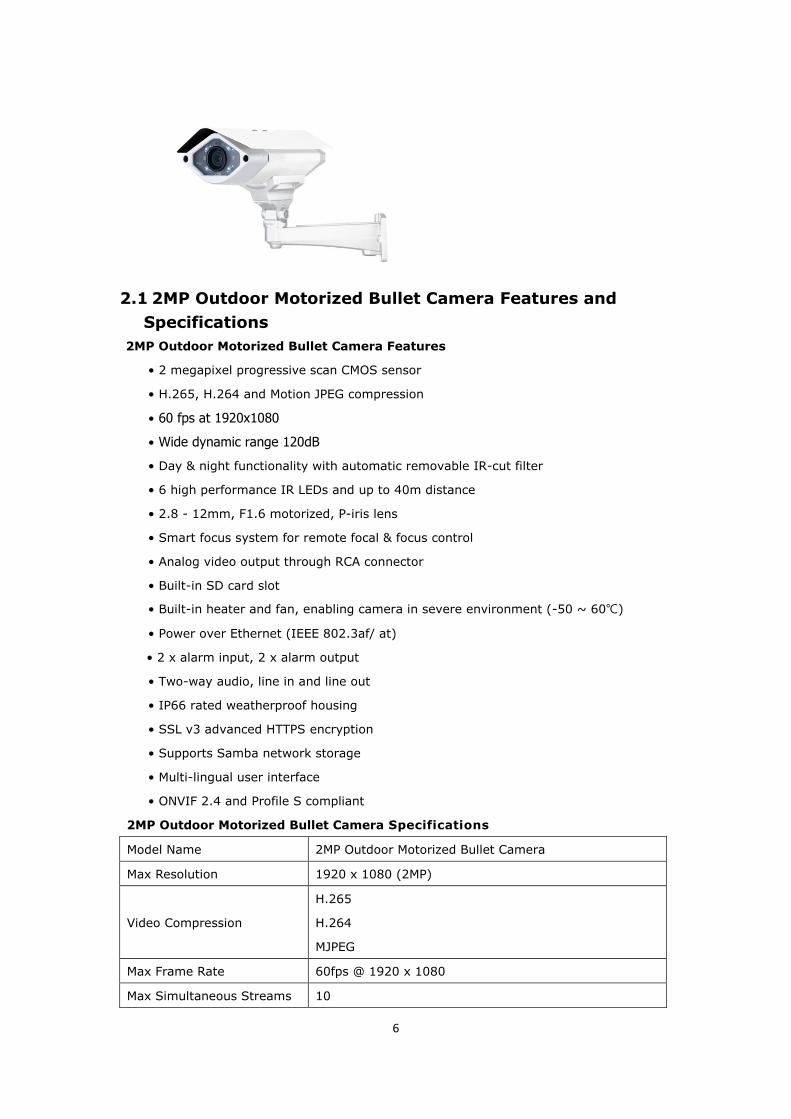
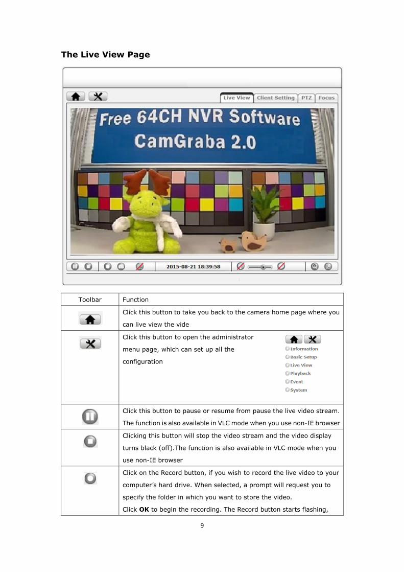
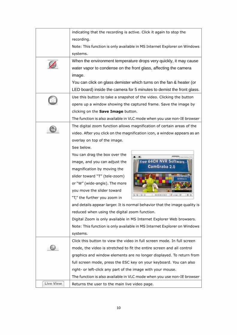
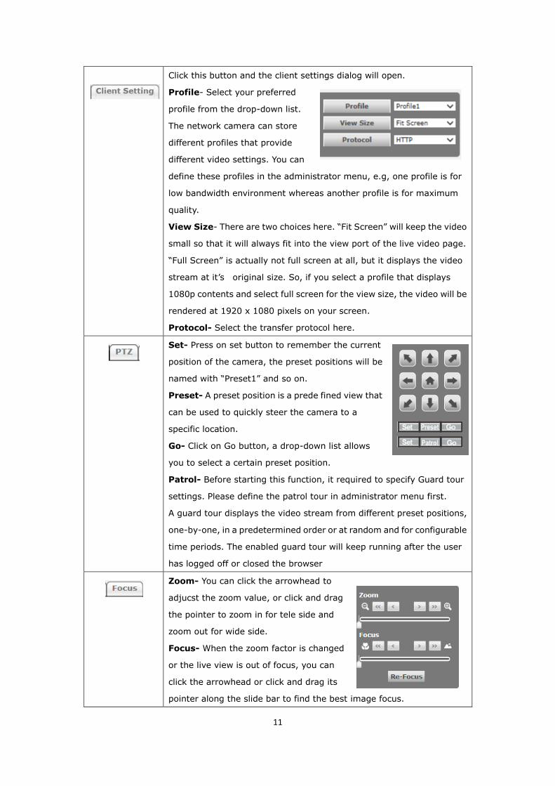
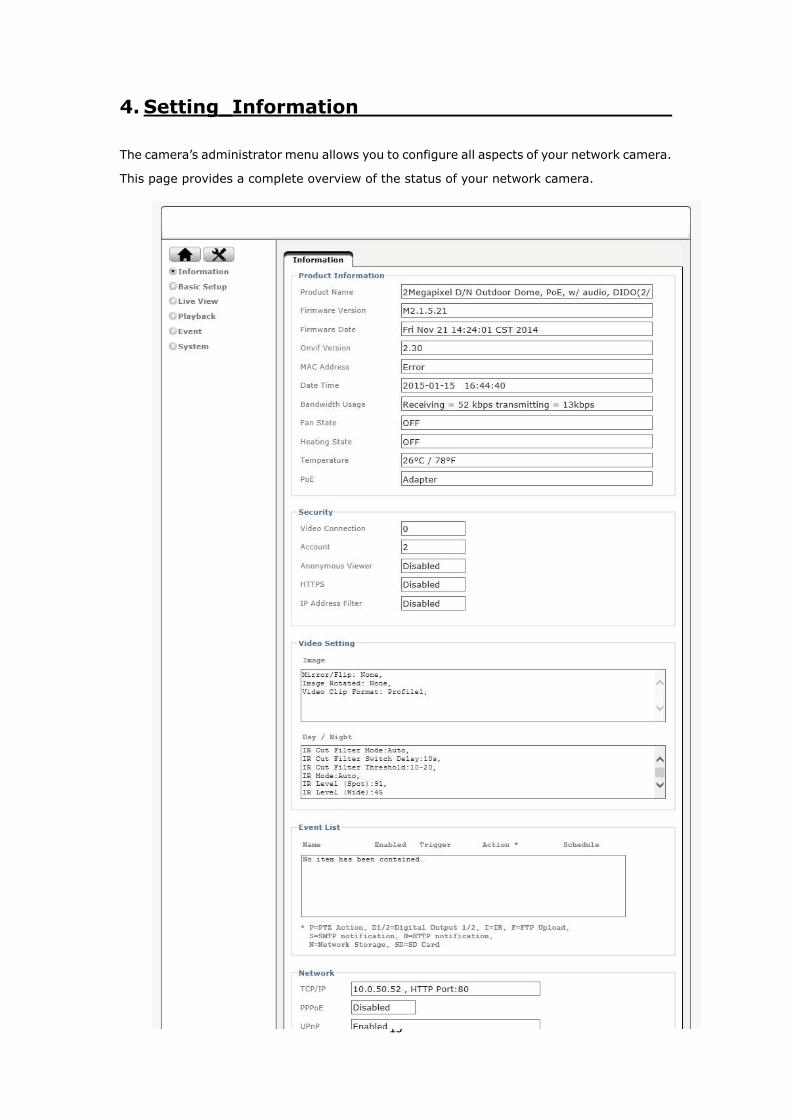
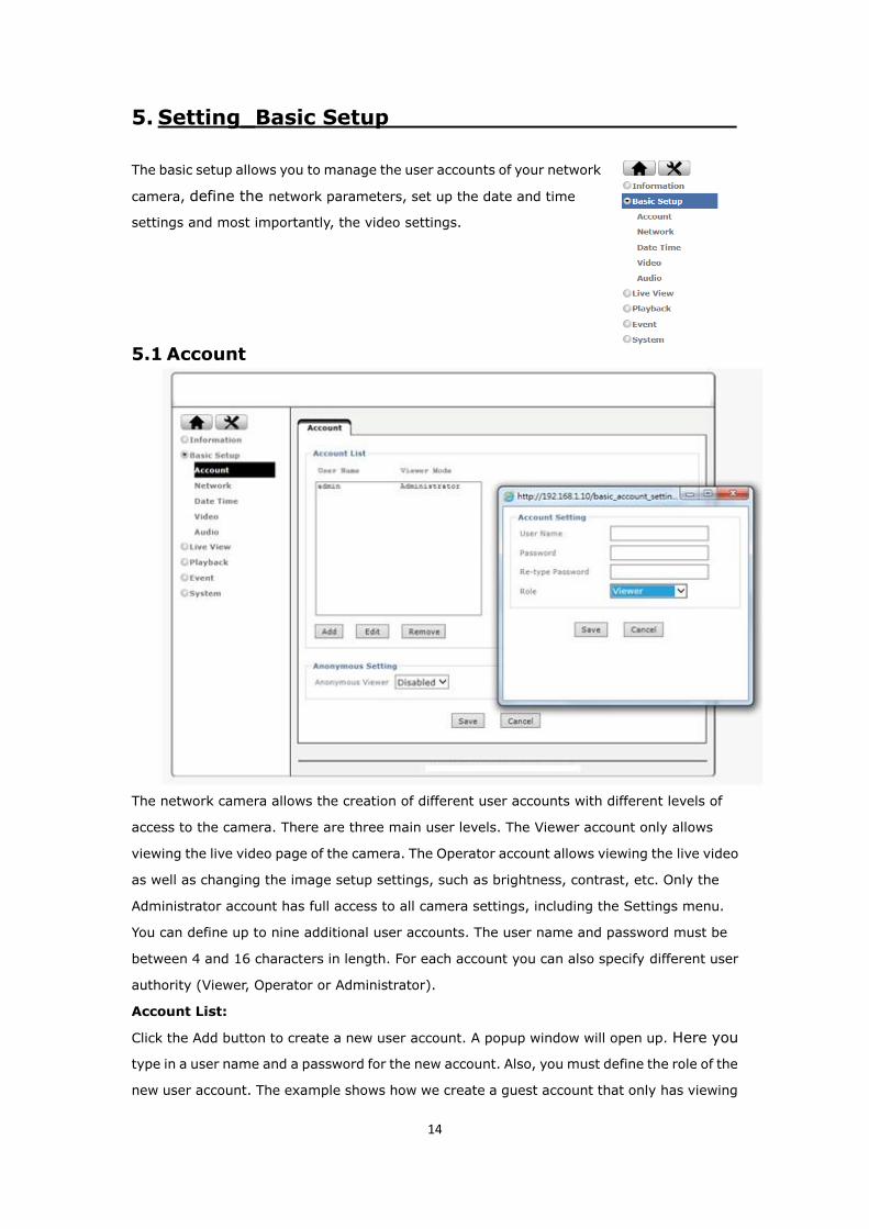
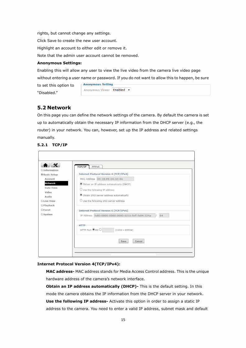
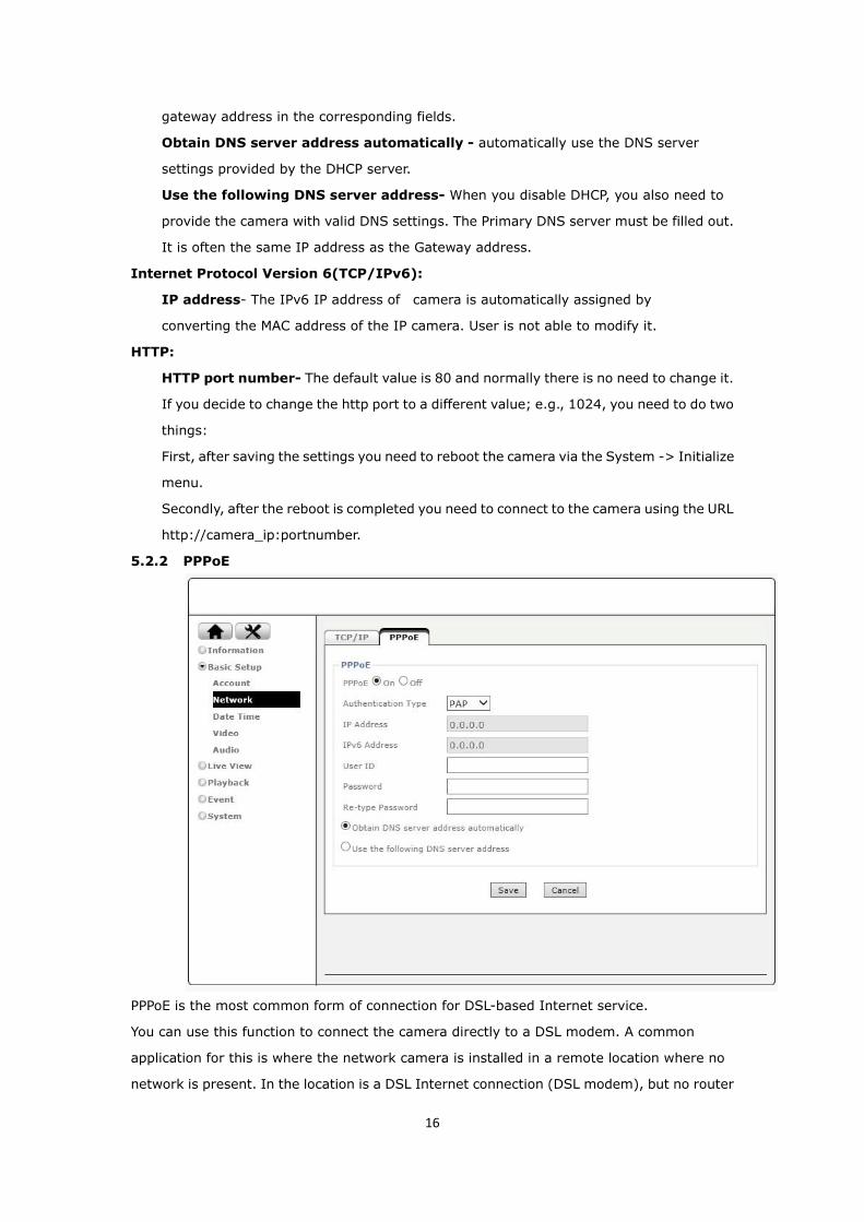
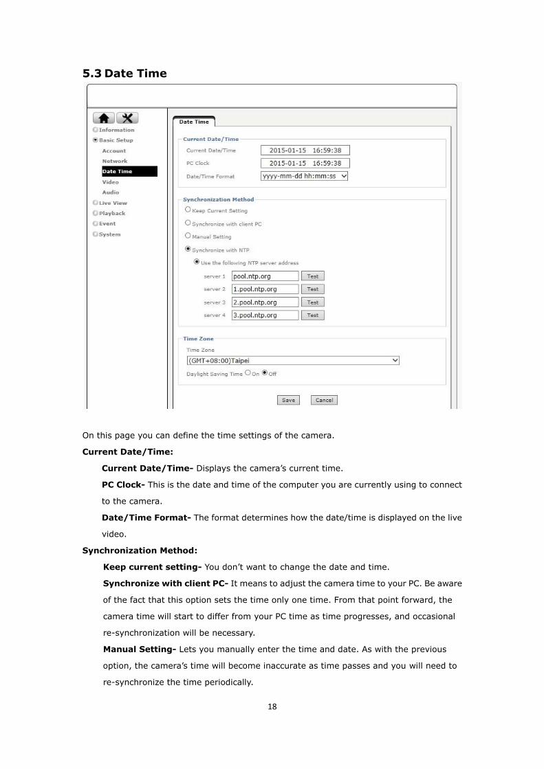
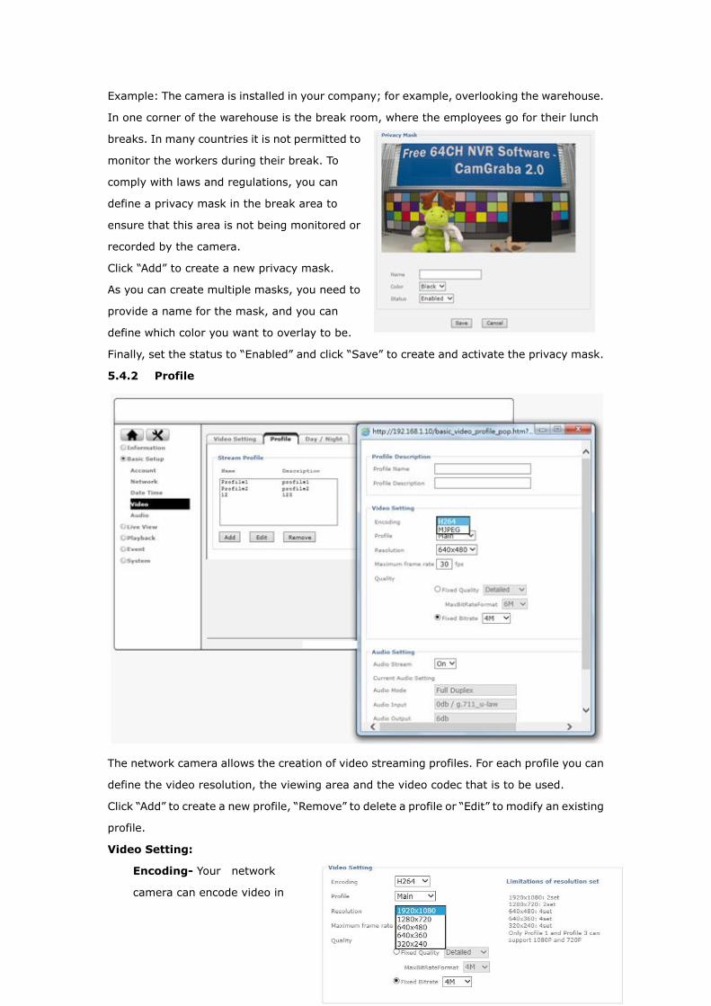
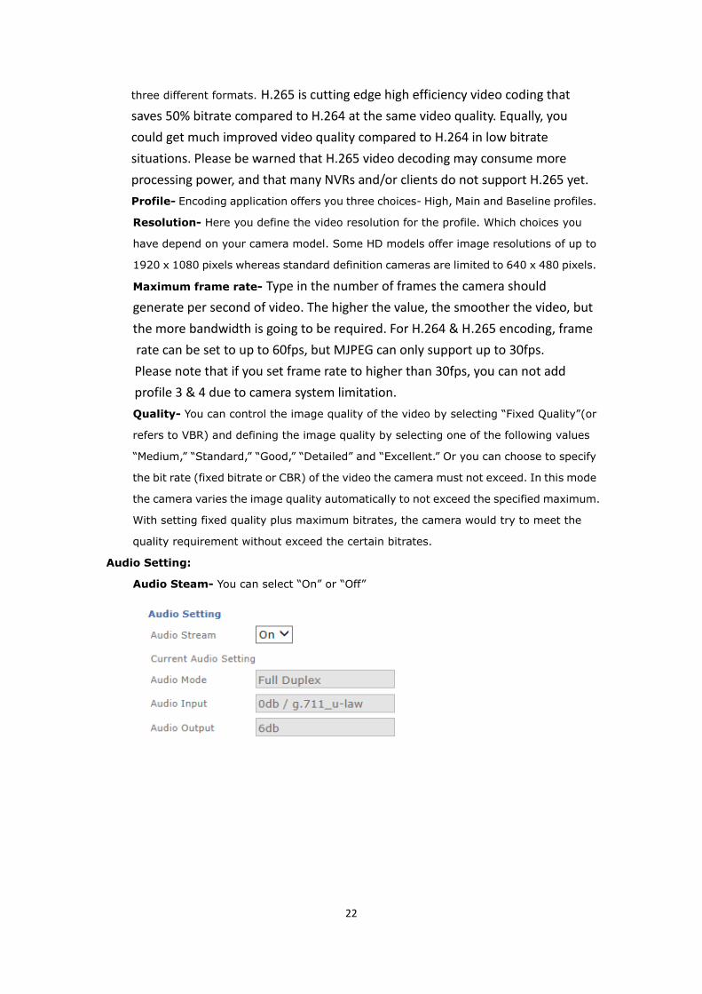
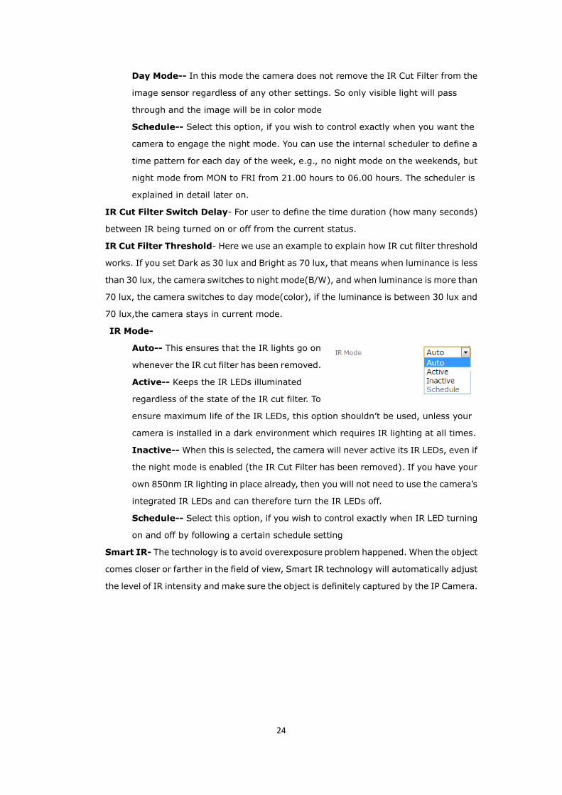
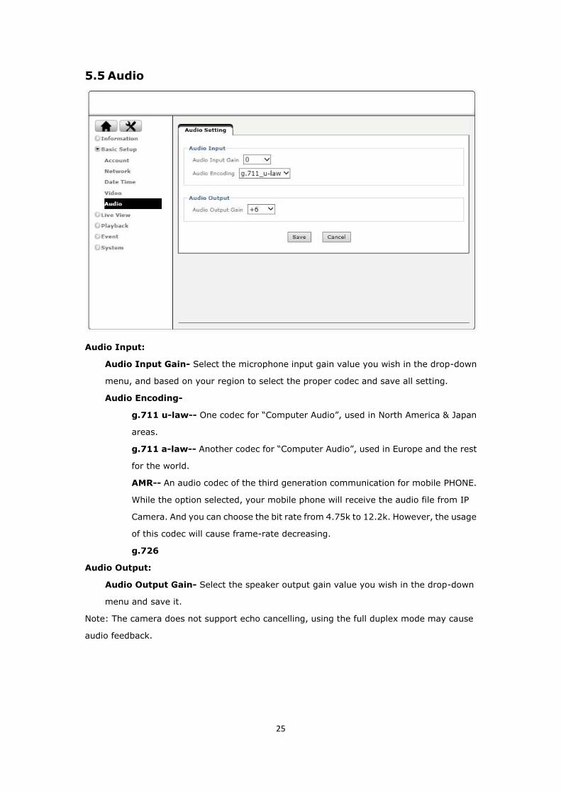
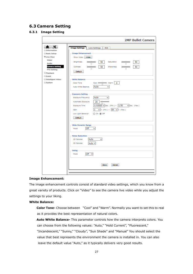
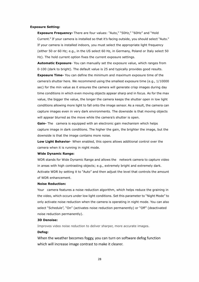
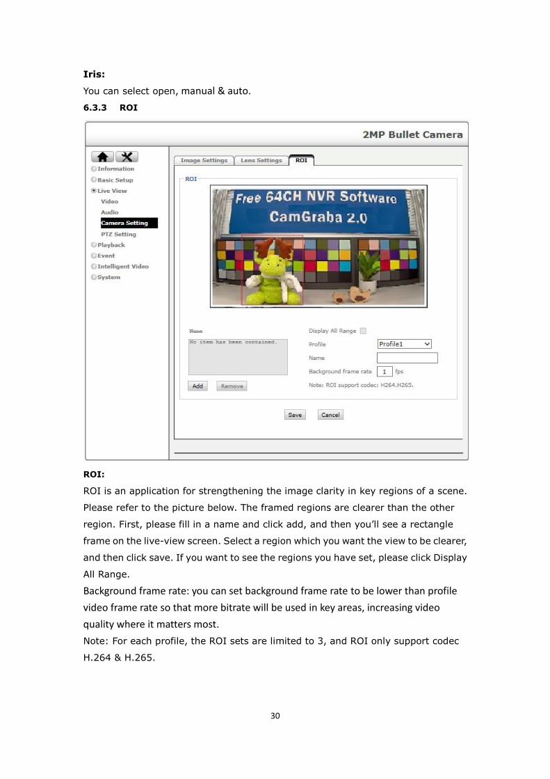
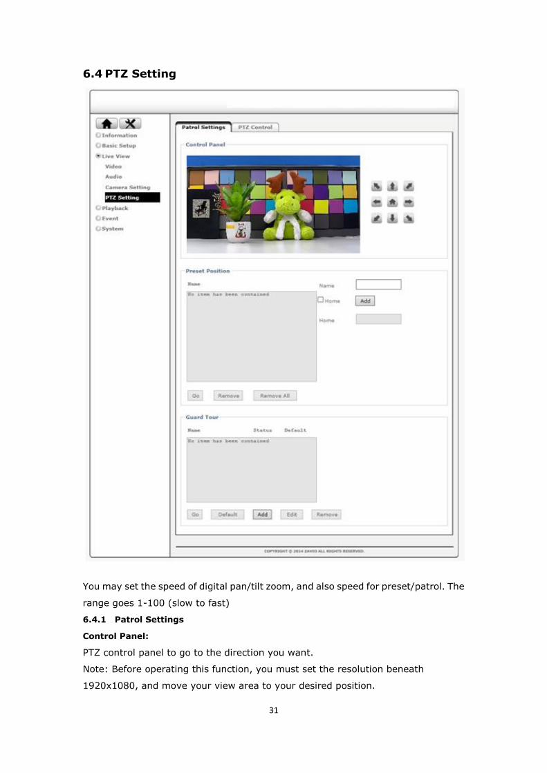
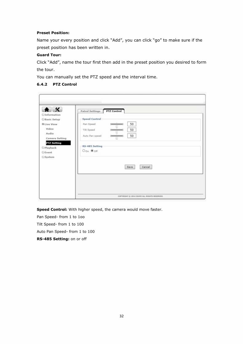
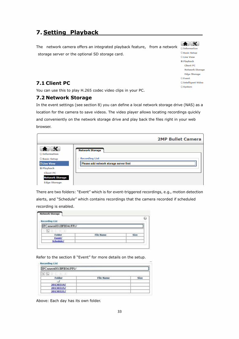
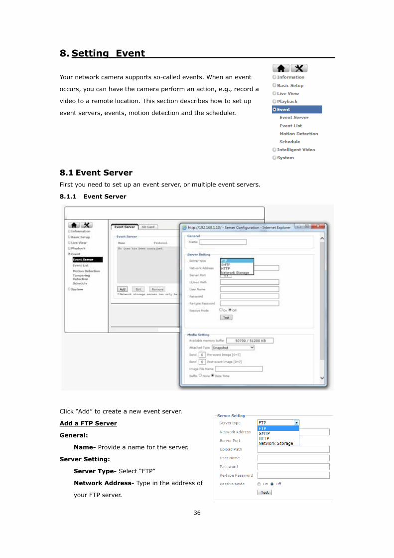
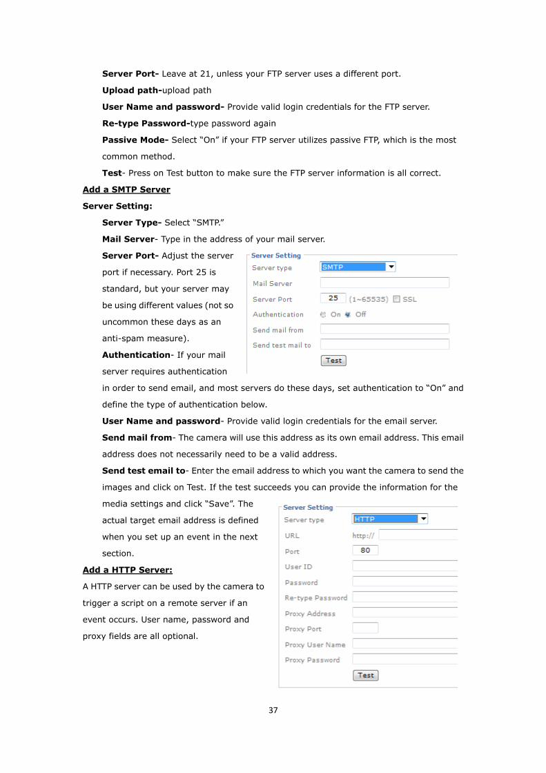
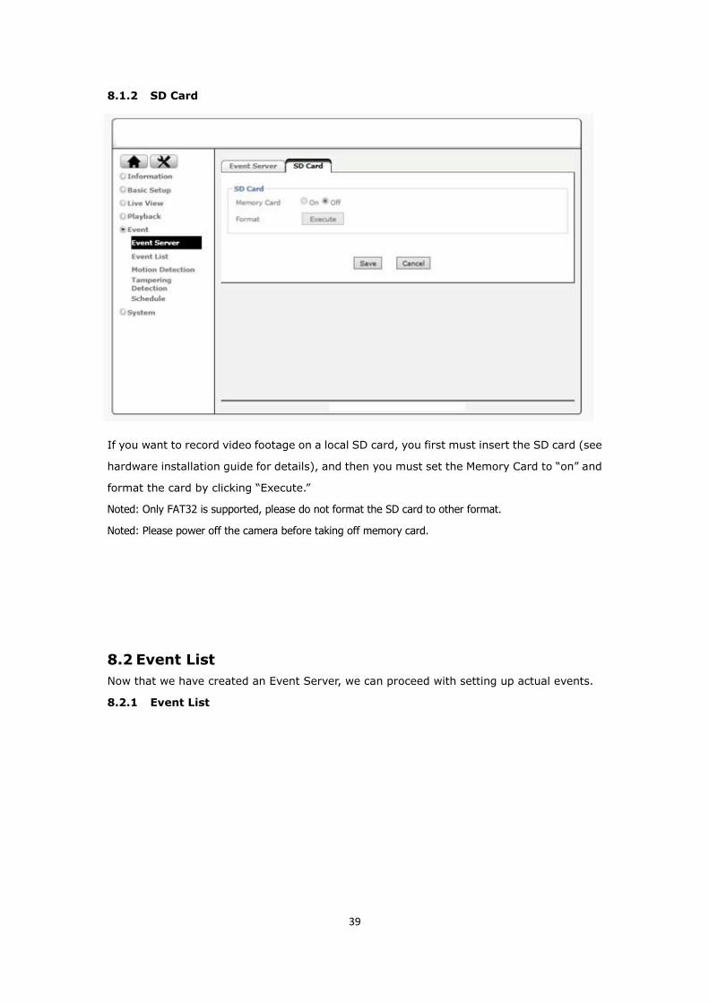
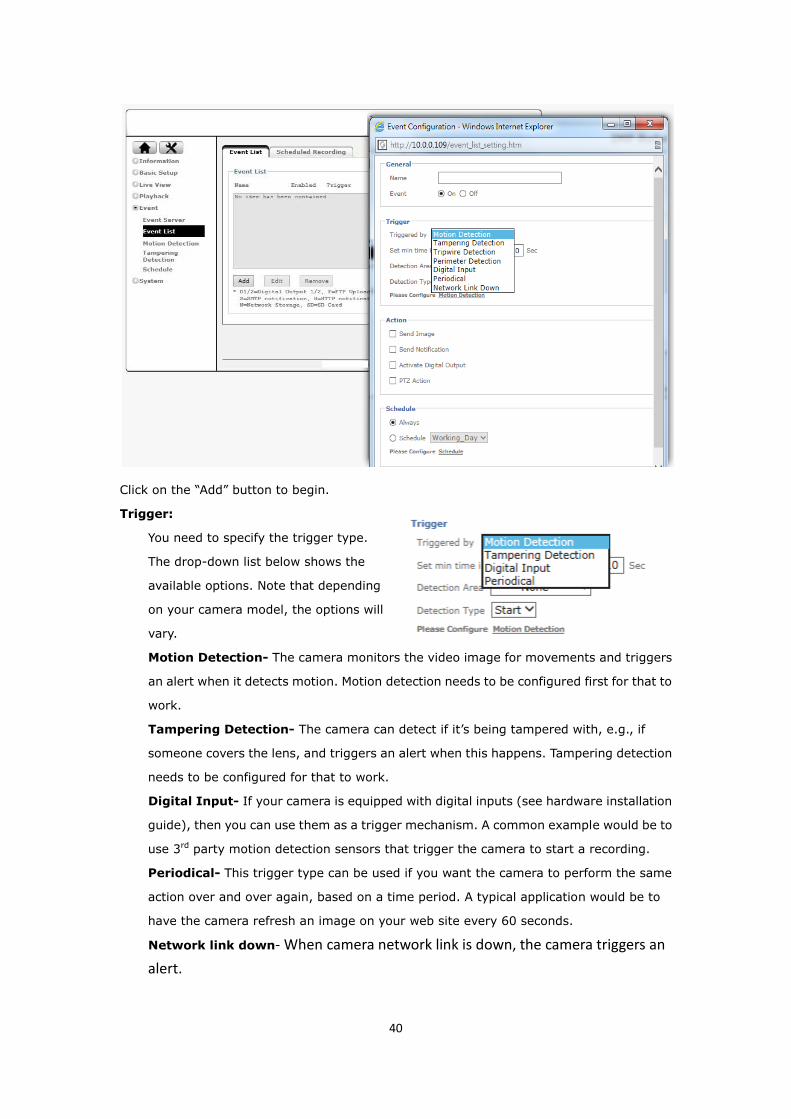
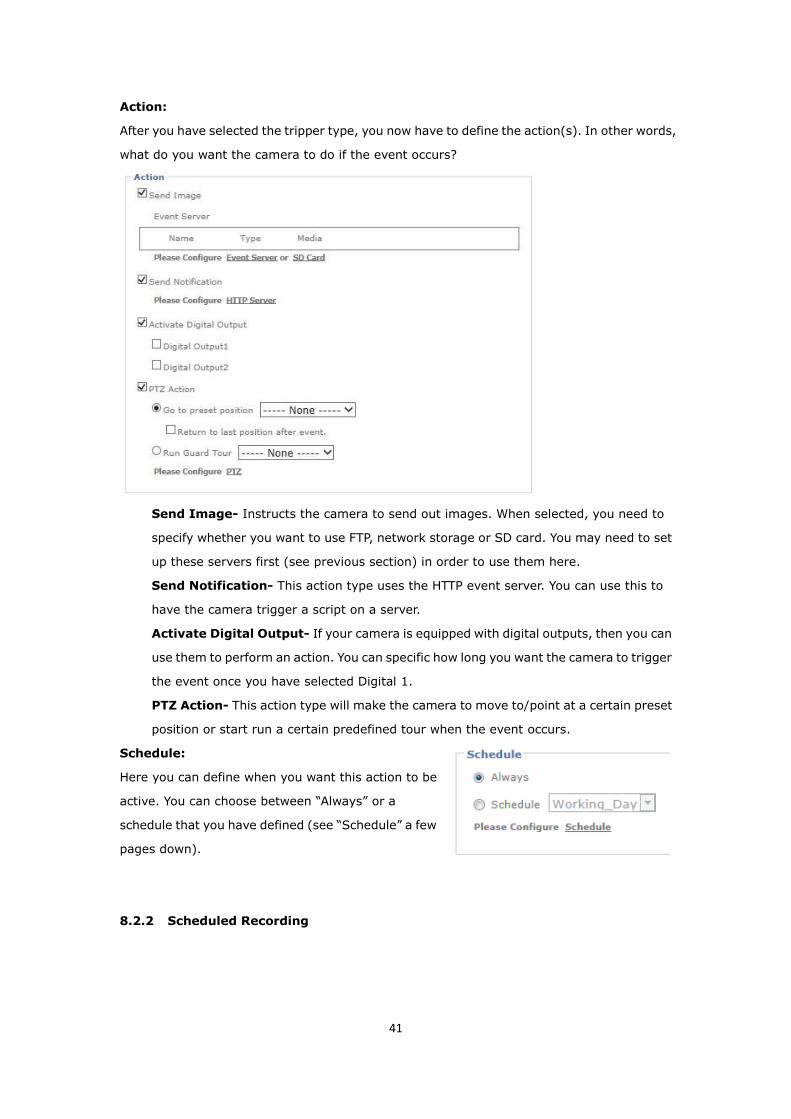
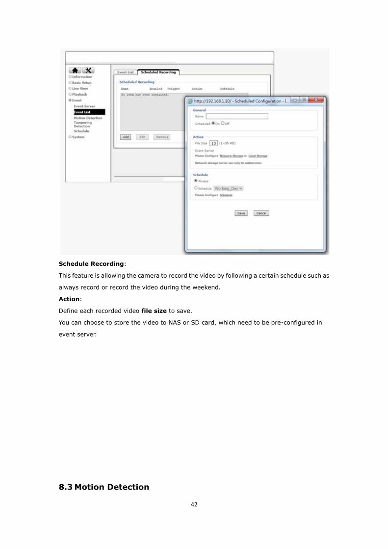
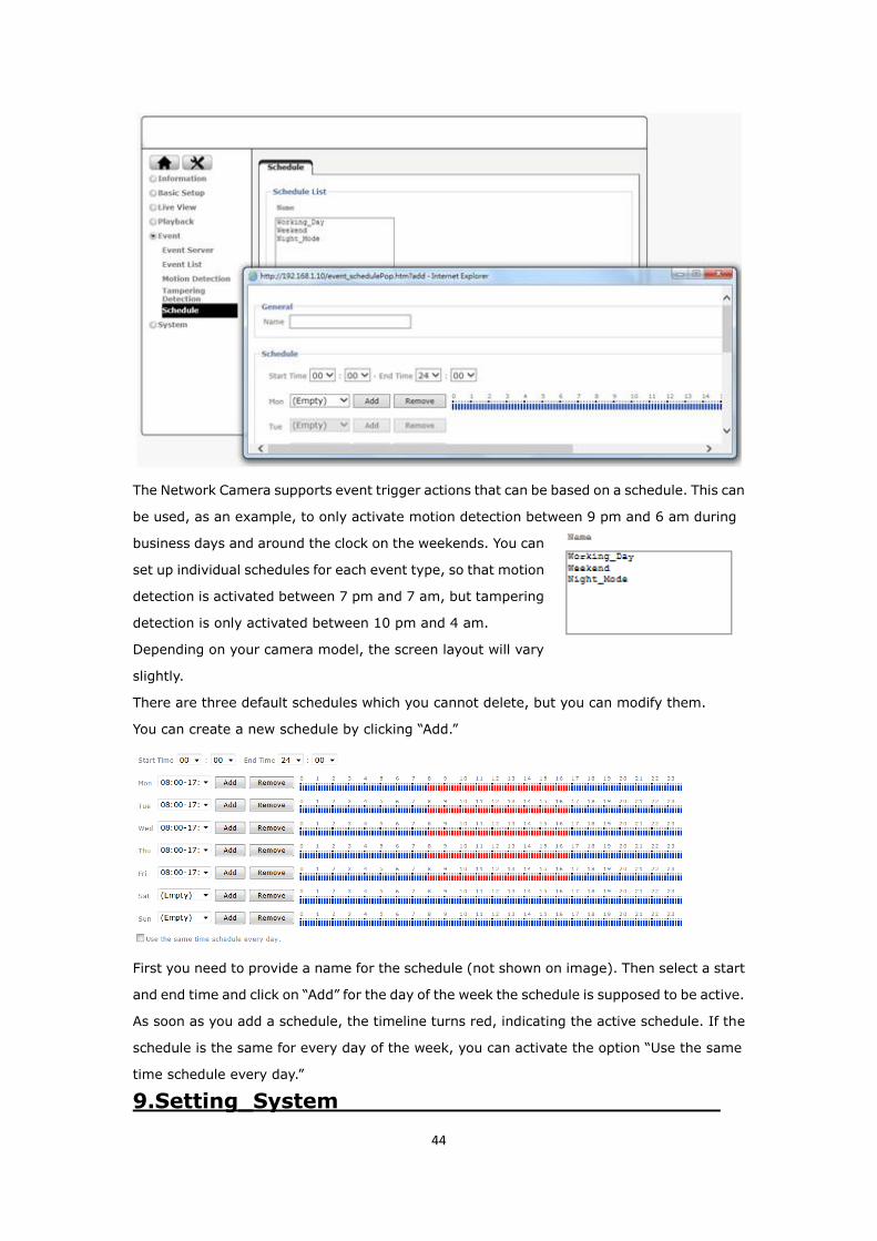
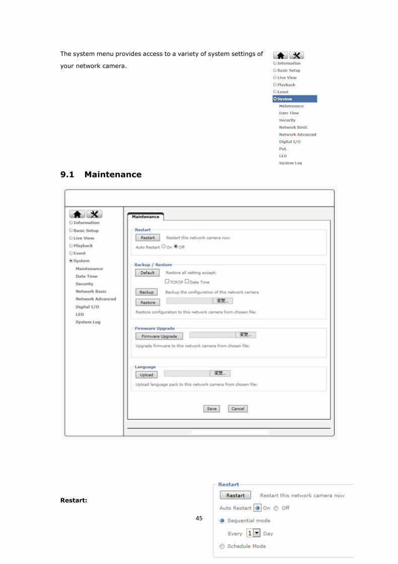
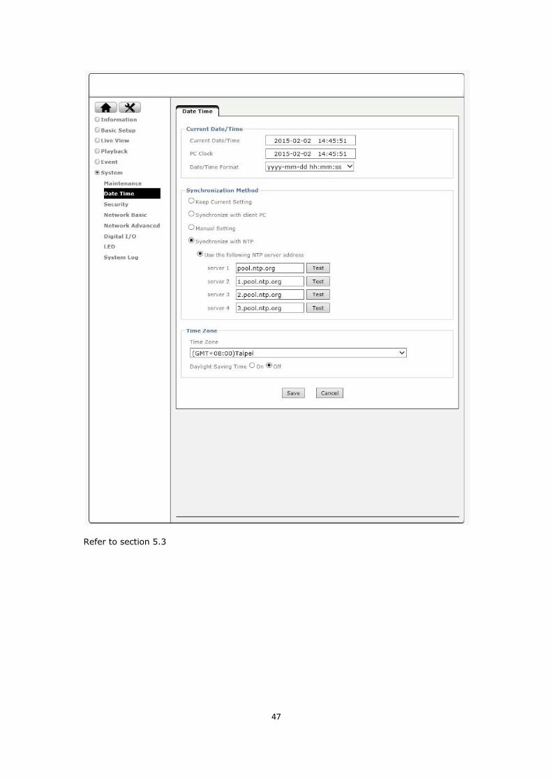
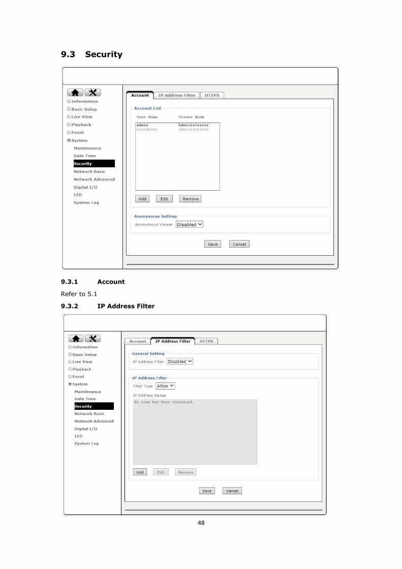
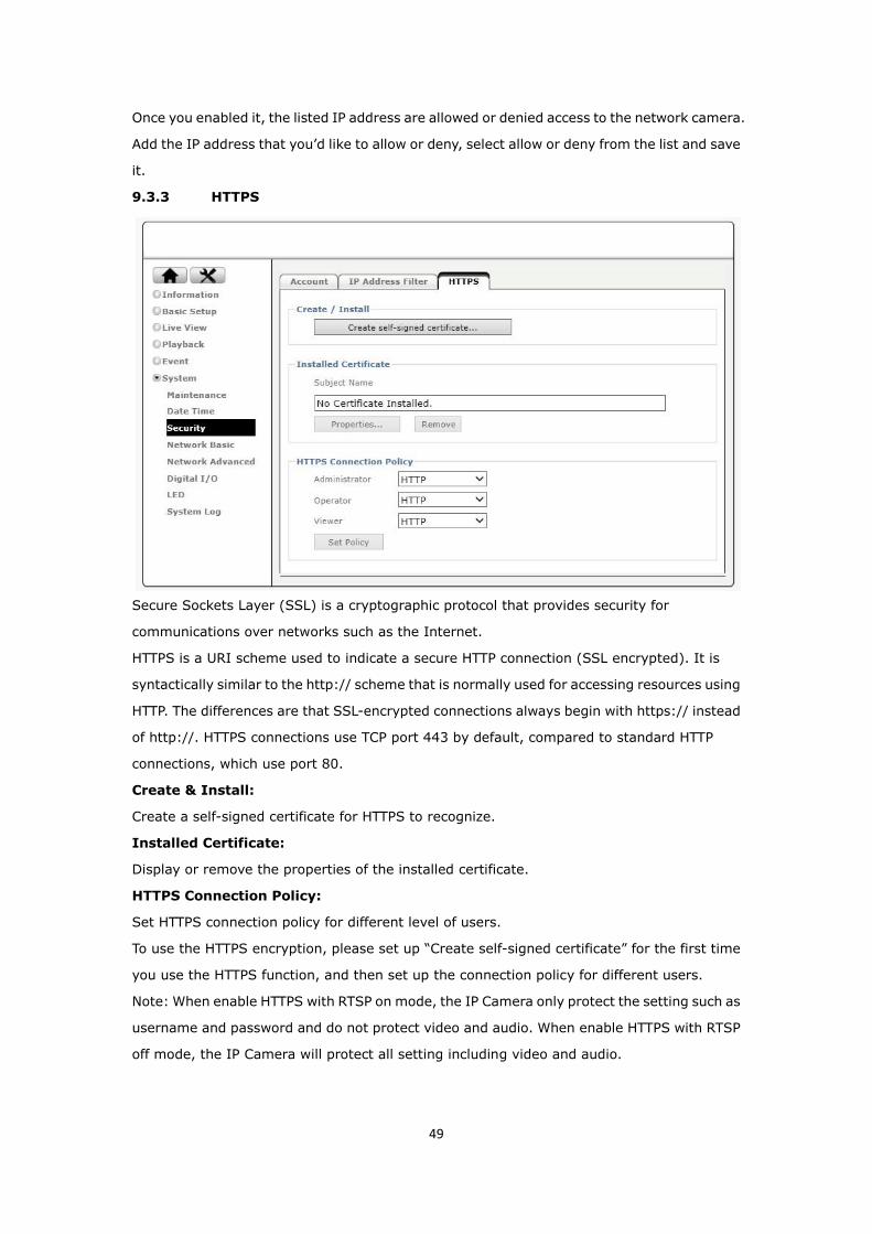
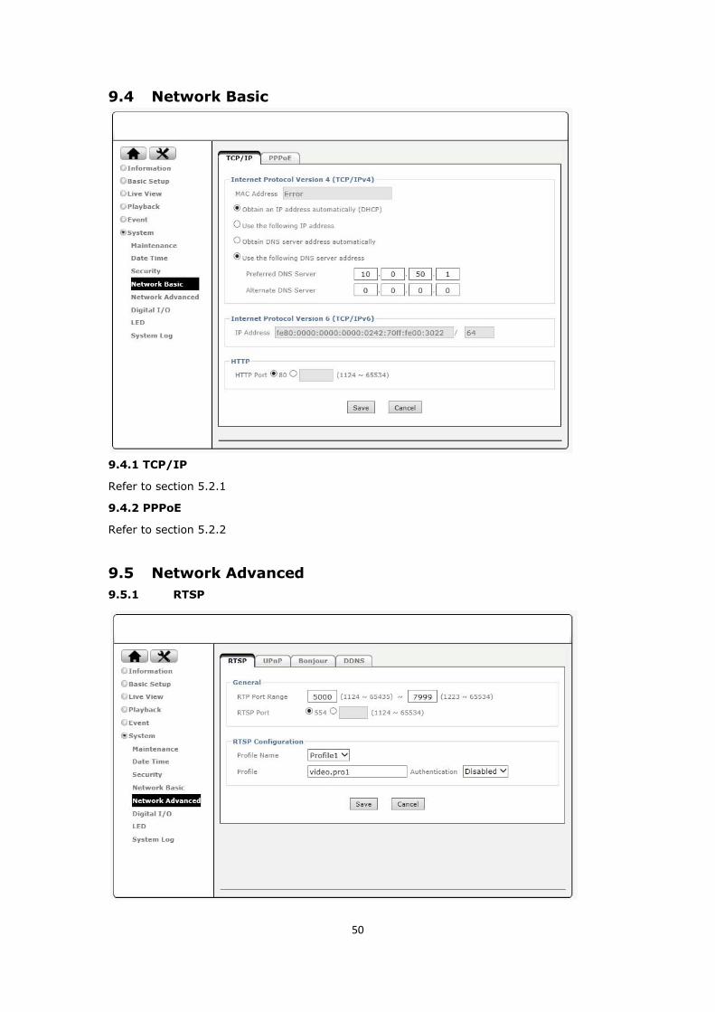
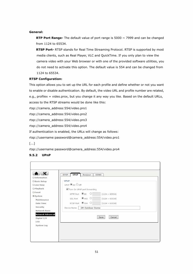
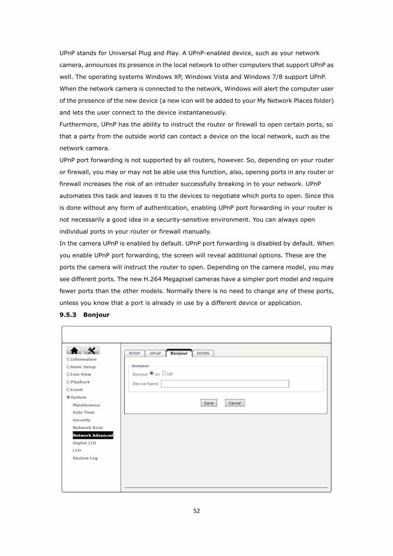
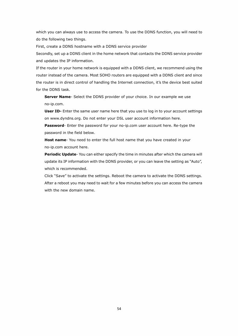
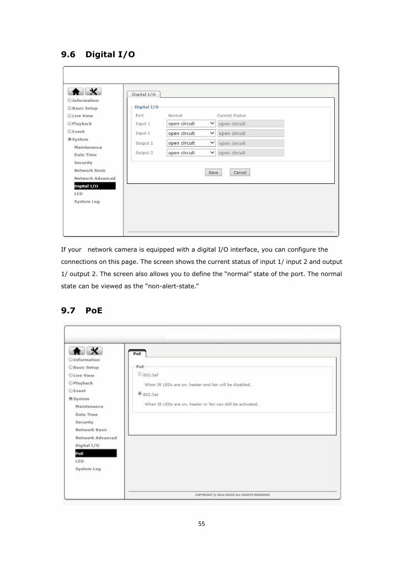
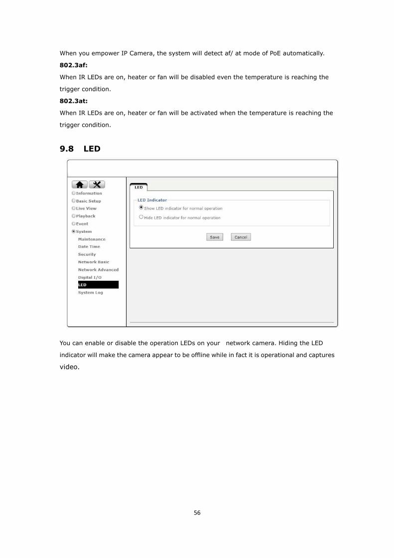
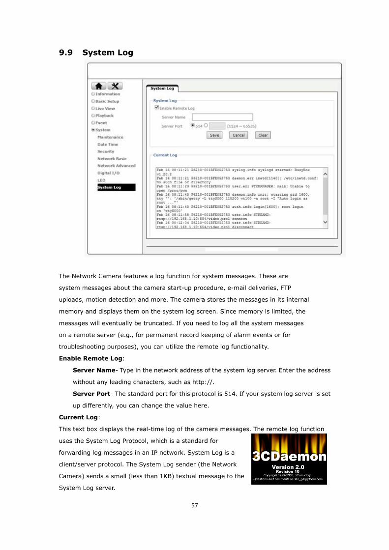
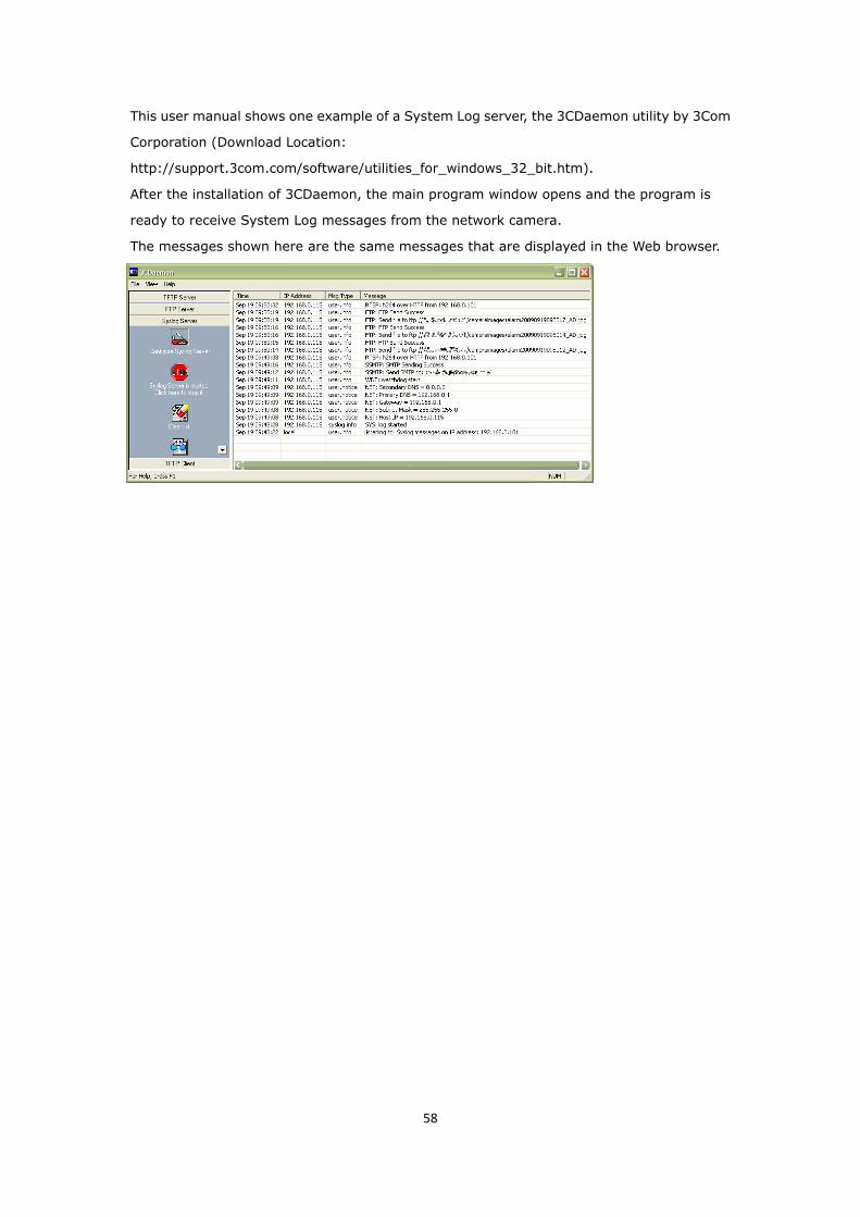

59


