
TABLE OF CONTENTS - Inspire Fitness OF CONTENTS BEFORE YOU BEGIN ... The CS2 CardioStrider has 2...
34
1
Transcript of TABLE OF CONTENTS - Inspire Fitness OF CONTENTS BEFORE YOU BEGIN ... The CS2 CardioStrider has 2...
1
TABLE OF CONTENTS
BEFORE YOU BEGIN...................................................................................……… 2 IMPORTANT SAFETY NOTICES.............................................................................3 WARNING LABEL PLACEMENT…………………………………………………4 HARDWARE PACK…............................................................................................... 5 ASSEMBLY INSTRUCTIONS...................................................................................6-17 COMPUTER OPERATION GUIDELINE……………….………………………….18-24 PARTS LIST………..………………………………………………………………..25-29 EXPLODED DIAGRAMS…….…………………………..…………………………30-32 WARRANTY.................................................................................................………..33
BEFORE YOU BEGIN
Thank you for selecting the INSPIRE CARDIOSTRIDER. For your safety and benefit, read this manual carefully before using the machine. As a manufacturer, we are committed to providing you complete customer satisfaction. If you have any questions or find that there are missing or damaged parts, please call our TOLL-FREE customer service number. Our Customer Service Agents will provide immediate assistance to you.
Toll-Free Customer Service Number 1-877-738-1729
Mon. - Fri. 8 a.m. - 5 p.m. PST www.inspirefitness.netwww.cardiostrider.com
2
IMPORTANT SAFETY NOTICE
PRECAUTIONS This exercise machine is built for optimum safety. However, certain precautions apply whenever you operate a piece of exercise equipment. Be sure to read the entire manual before you assemble or operate your machine. In particular, note the following safety precautions: 1. Keep children and pets away from the machine at all times. DO NOT leave children unattended in the
same room with the machine. The linkages on this machine can cause serious injury or death if used improperly.
1. 2. Never place your hands or feet in the path of the linkages because injury may occur to you or damage may occur to the equipment. Never allow children to come near or approach the moving linkages while in use. 2. 3. If the user experiences dizziness, nausea, chest pain, or any other abnormal symptoms, STOP the workout at once. CONSULT A PHYSICIAN IMMEDIATELY. 3. 4. Position the machine on a clear, leveled surface. DO NOT use the machine near water or outdoors. 4. 5. Keep hands away from all moving parts. 5. 6. Always wear appropriate workout clothing when exercising. DO NOT wear robes or other clothing that could become caught in the machine. Running or aerobic shoes are also required when using the machine. 6. 7. Use the machine only for its intended use as described in this manual. DO NOT use attachments not recommended by the manufacturer. 7. 8. Do not place any sharp object around the machine. 8. 9. Disabled persons should not use the machine without a qualified person or physician in attendance. 9. 10. Before using the machine to exercise, always do stretching exercises to properly warm up. 10. 11. Never operate the machine if the machine is not functioning properly. 11. 12. Maximum user weight 300 lbs. CARE AND MAINTENANCE 1. 1. Keep seat slider clean 2. 2. Inspect and tighten all parts before using the machine. 3. 3. The Frame and Seat Pad of the machine can be cleaned using a damp cloth and mild non-abrasive detergent. DO NOT use solvents. WARNING: BEFORE BEGINNING ANY EXERCISE PROGRAM, CONSULT YOUR PHYSICIAN. THIS IS ESPECIALLY IMPORTANT FOR INDIVIDUALS OVER THE AGE OF 35 OR PERSONS WITH PRE-EXISTING HEALTH PROBLEMS. READ ALL INSTRUCTIONS BEFORE USING ANY FITNESS EQUIPMENT. Neither Health In Motion, LLC. nor FG1, LLC. ASSUMES ANY RESPONSIBILITY FOR PERSONAL INJURY OR PROPERTY DAMAGE SUSTAINED BY OR THROUGH THE USE OF THIS PRODUCT. SAVE THESE INSTRUCTIONS.
3
CARDIOSTRIDER ASSEMBLY INSTRUCTION
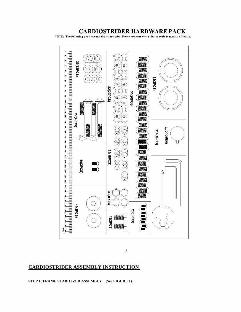
STEP 1: FRAME STABILIZER ASSEMBLY (See FIGURE 1)
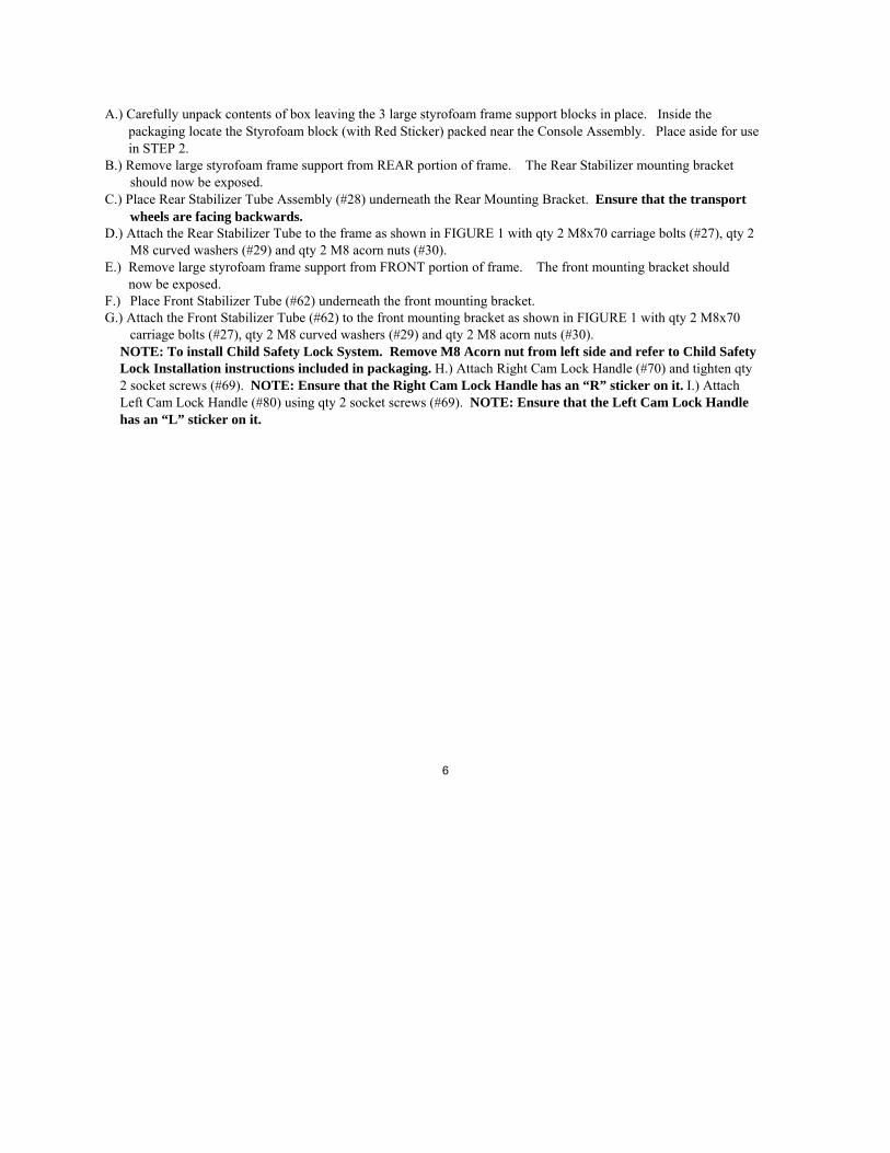
A.) Carefully unpack contents of box leaving the 3 large styrofoam frame support blocks in place. Inside the packaging locate the Styrofoam block (with Red Sticker) packed near the Console Assembly. Place aside for use in STEP 2.
B.) Remove large styrofoam frame support from REAR portion of frame. The Rear Stabilizer mounting bracket should now be exposed.
C.) Place Rear Stabilizer Tube Assembly (#28) underneath the Rear Mounting Bracket. Ensure that the transport wheels are facing backwards.
D.) Attach the Rear Stabilizer Tube to the frame as shown in FIGURE 1 with qty 2 M8x70 carriage bolts (#27), qty 2 M8 curved washers (#29) and qty 2 M8 acorn nuts (#30).
E.) Remove large styrofoam frame support from FRONT portion of frame. The front mounting bracket should now be exposed.
F.) Place Front Stabilizer Tube (#62) underneath the front mounting bracket. G.) Attach the Front Stabilizer Tube (#62) to the front mounting bracket as shown in FIGURE 1 with qty 2 M8x70
carriage bolts (#27), qty 2 M8 curved washers (#29) and qty 2 M8 acorn nuts (#30). NOTE: To install Child Safety Lock System. Remove M8 Acorn nut from left side and refer to Child Safety Lock Installation instructions included in packaging. H.) Attach Right Cam Lock Handle (#70) and tighten qty 2 socket screws (#69). NOTE: Ensure that the Right Cam Lock Handle has an “R” sticker on it. I.) Attach Left Cam Lock Handle (#80) using qty 2 socket screws (#69). NOTE: Ensure that the Left Cam Lock Handle has an “L” sticker on it.
6
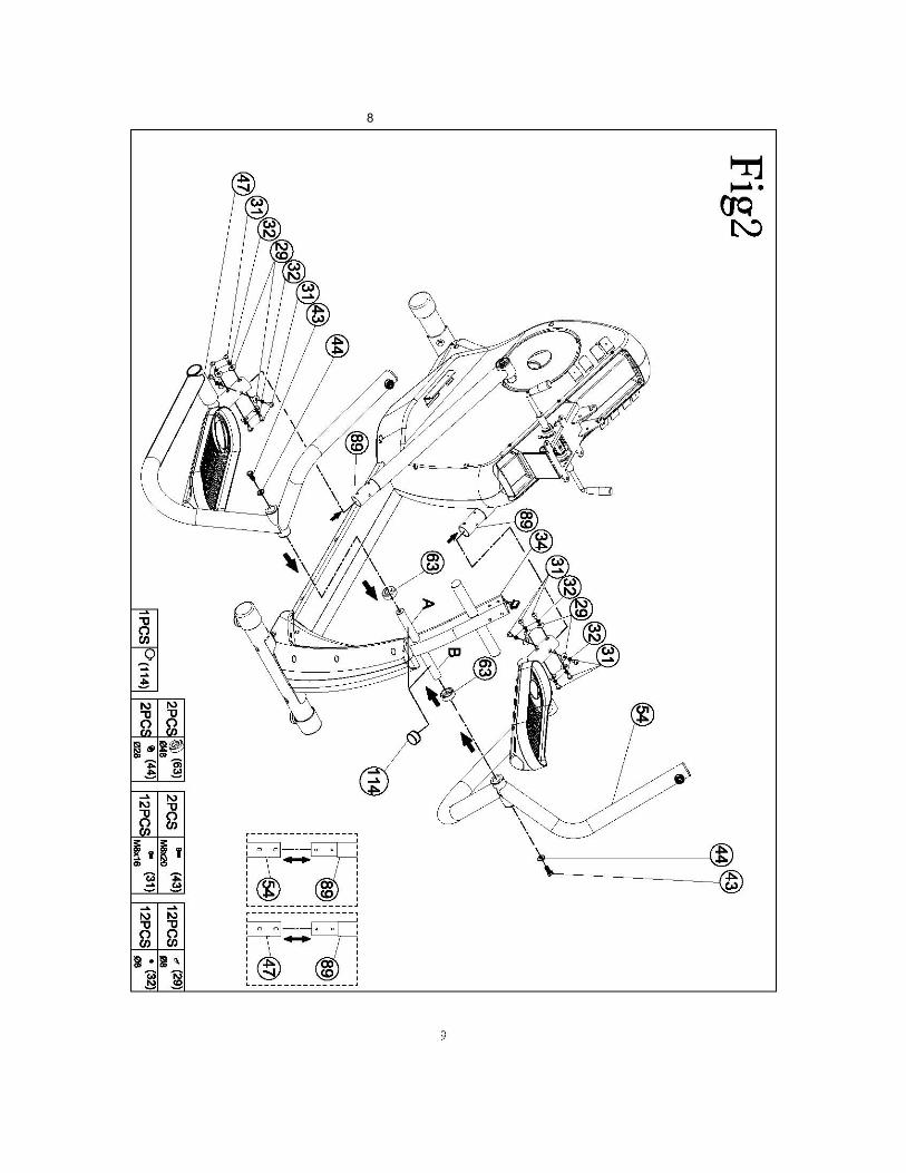
STEP 2: SWING ARM ASSEMBLY (See FIGURE 2)
A.) Place Arm Spacer (#63) on right side of Frame Pivot Shaft (A) with open end
facing inward. NOTE: Failure to assemble this part correctly will result in permanent damage to the machine during use!
B.) Place Right Lower Pedal Arm Assembly (#47) on Front Pivot Shaft (A). Secure using qty 1 Oversized Flat Washer (#44) and qty 1 M8x20 Hex Bolt (#43). NOTE: When assembling Pedal Arm put finger inside the Bearing Pivot to ensure spacer is centered. Without the Spacer centered you will not be able to place the Pedal Arm on the Shaft.
C.) Place the Right Lower Pedal Arm Assembly (#47) on top of the Styrofoam Support Block (with Red Dot) so the ball bearing connection assembly sits on top of the Styrofoam Support Block.
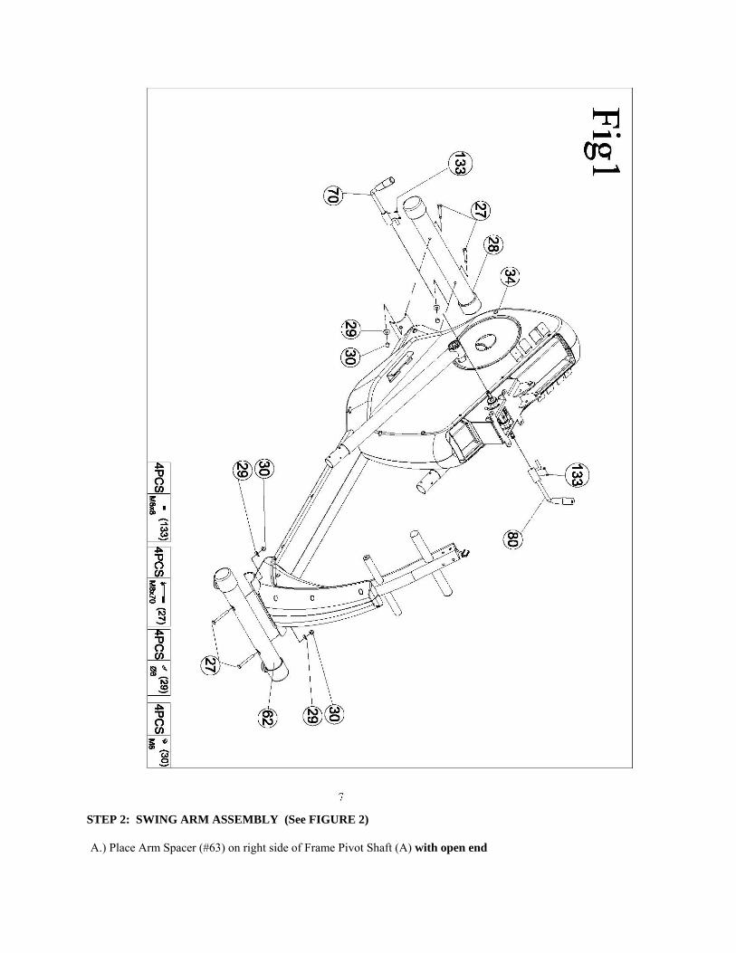
D.) Secure the Right Upper Pedal Arm Assembly (#89) to the Right Lower Pedal Arm Assembly (#47) as shown below using qty 6 Curved Washers (#29), qty 6 Lock Washers (#32) and qty 6 M8x16 socket screws (#31).
E.) Place Arm Spacer (#63) on left side of Frame Pivot Shaft (B) with open end facing inward. NOTE: Failure to assemble this part correctly will result in permanent damage to the machine during use!
F.) Place Left Lower Pedal Arm Assembly (#54) on Front Pivot Shaft (B). Secure using, qty 1 Oversized Flat washer (#44) and qty 1 M8x20 Hex Bolt (#43). NOTE: When assembling Pedal Arm put finger inside the Bearing Pivot to ensure spacer is centered. Without the Spacer centered you will not be able to place the Pedal Arm on the Shaft.
G.) Place the Left Lower Pedal Arm Assembly (#54) on top of the Styrofoam Support Block (with Red Dot) so the ball bearing connection assembly sits on top of the Styrofoam Support Block.
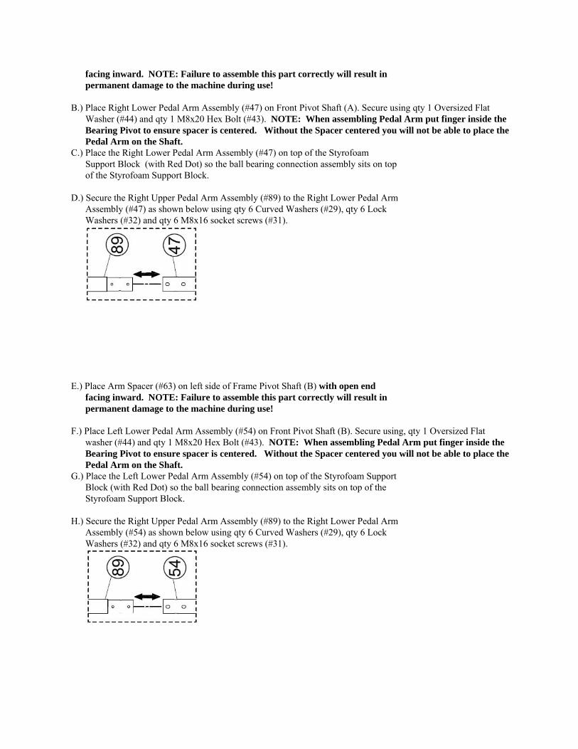
H.) Secure the Right Upper Pedal Arm Assembly (#89) to the Right Lower Pedal Arm Assembly (#54) as shown below using qty 6 Curved Washers (#29), qty 6 Lock Washers (#32) and qty 6 M8x16 socket screws (#31).
8
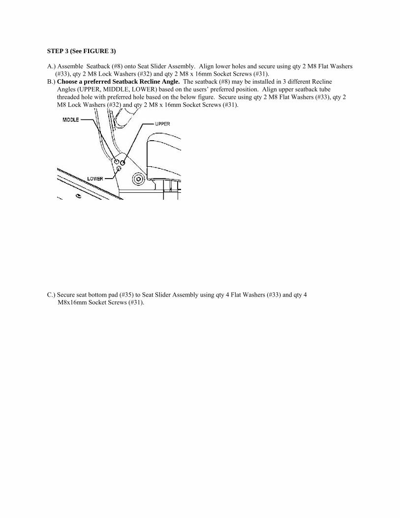
STEP 3 (See FIGURE 3)
A.) Assemble Seatback (#8) onto Seat Slider Assembly. Align lower holes and secure using qty 2 M8 Flat Washers (#33), qty 2 M8 Lock Washers (#32) and qty 2 M8 x 16mm Socket Screws (#31).
B.) Choose a preferred Seatback Recline Angle. The seatback (#8) may be installed in 3 different Recline Angles (UPPER, MIDDLE, LOWER) based on the users’ preferred position. Align upper seatback tube threaded hole with preferred hole based on the below figure. Secure using qty 2 M8 Flat Washers (#33), qty 2 M8 Lock Washers (#32) and qty 2 M8 x 16mm Socket Screws (#31).
C.) Secure seat bottom pad (#35) to Seat Slider Assembly using qty 4 Flat Washers (#33) and qty 4 M8x16mm Socket Screws (#31).
10
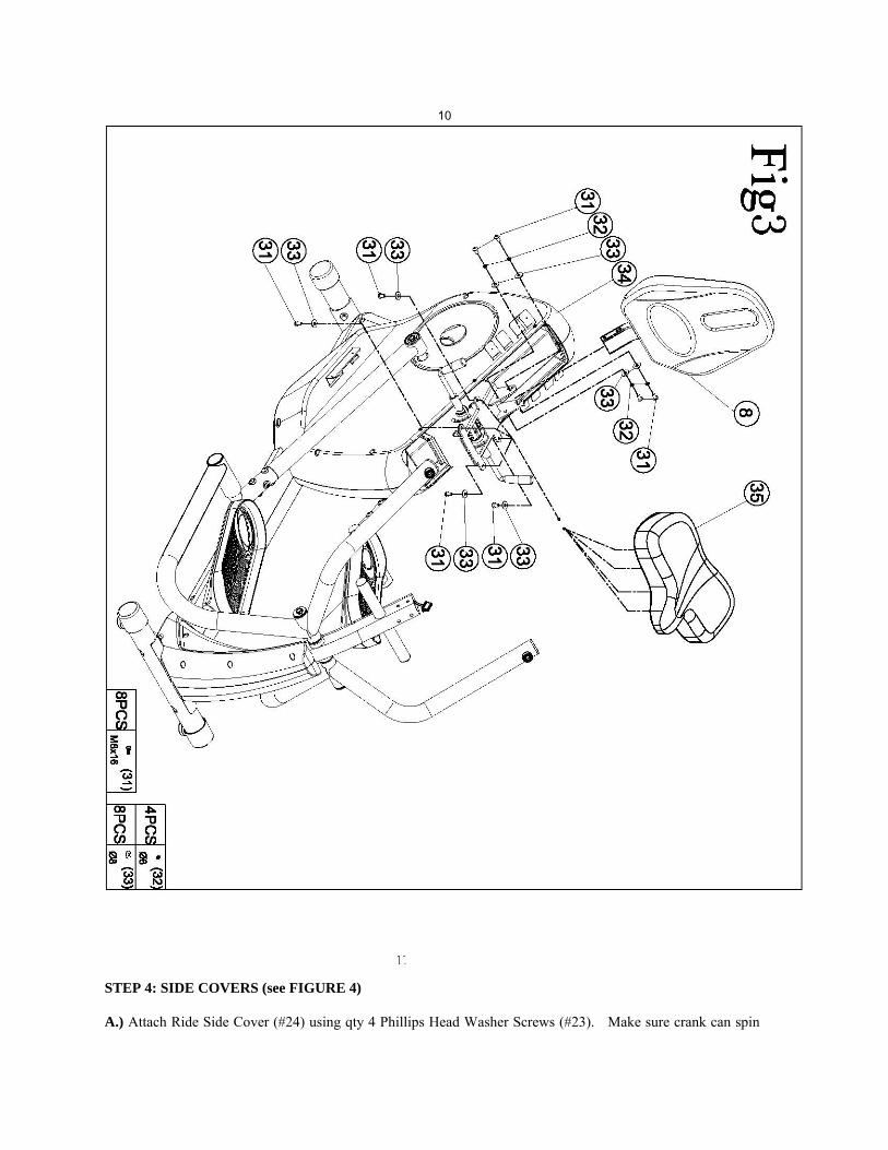
STEP 4: SIDE COVERS (see FIGURE 4)
A.) Attach Ride Side Cover (#24) using qty 4 Phillips Head Washer Screws (#23). Make sure crank can spin

freely with no side cover interference. B.) Attach Left Side Cover (#36) using qty 4 Phillips Head Washer Screws (#23). Make sure crank can spin freely
with no side cover interference.
12
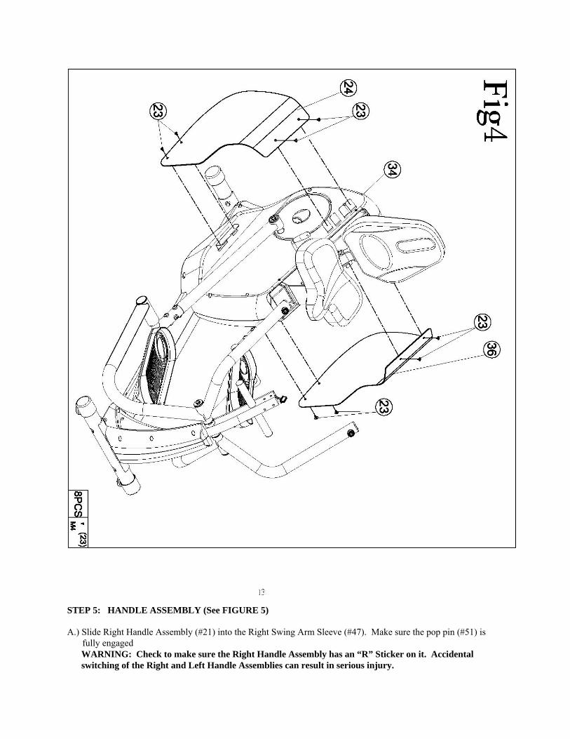
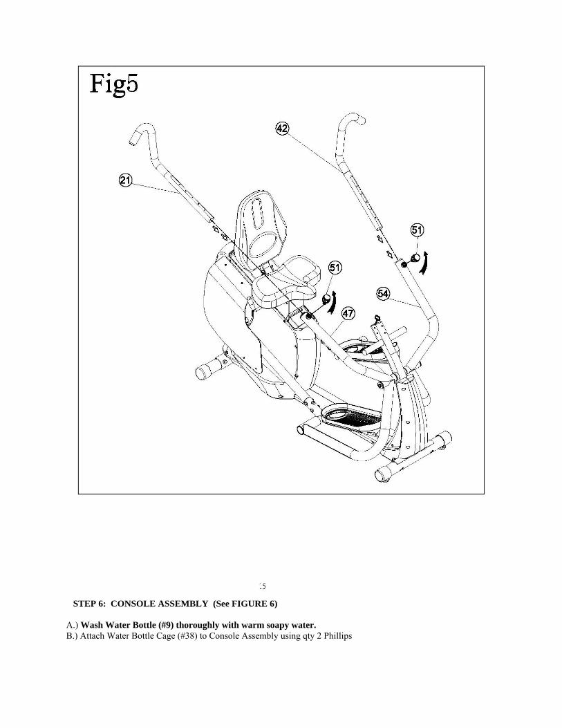
STEP 5: HANDLE ASSEMBLY (See FIGURE 5)
A.) Slide Right Handle Assembly (#21) into the Right Swing Arm Sleeve (#47). Make sure the pop pin (#51) is fully engaged WARNING: Check to make sure the Right Handle Assembly has an “R” Sticker on it. Accidental switching of the Right and Left Handle Assemblies can result in serious injury.

B.) Slide Left Handle Assembly (#42) into the Left Swing Arm Sleeve (#51). Make sure the pop pin (#51) is fully engaged WARNING: Check to make sure the Left Handle Assembly has an “L” Sticker on it. Accidental switching of the Right and Left Handle Assemblies can result in serious injury.
14
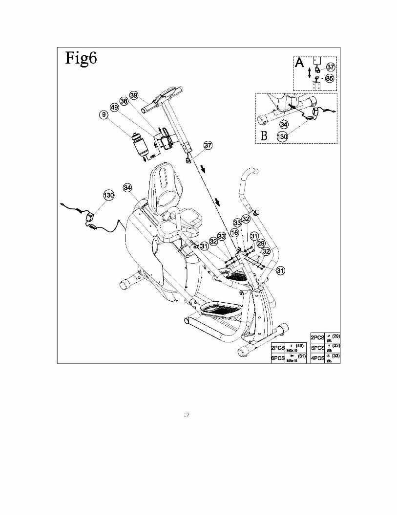
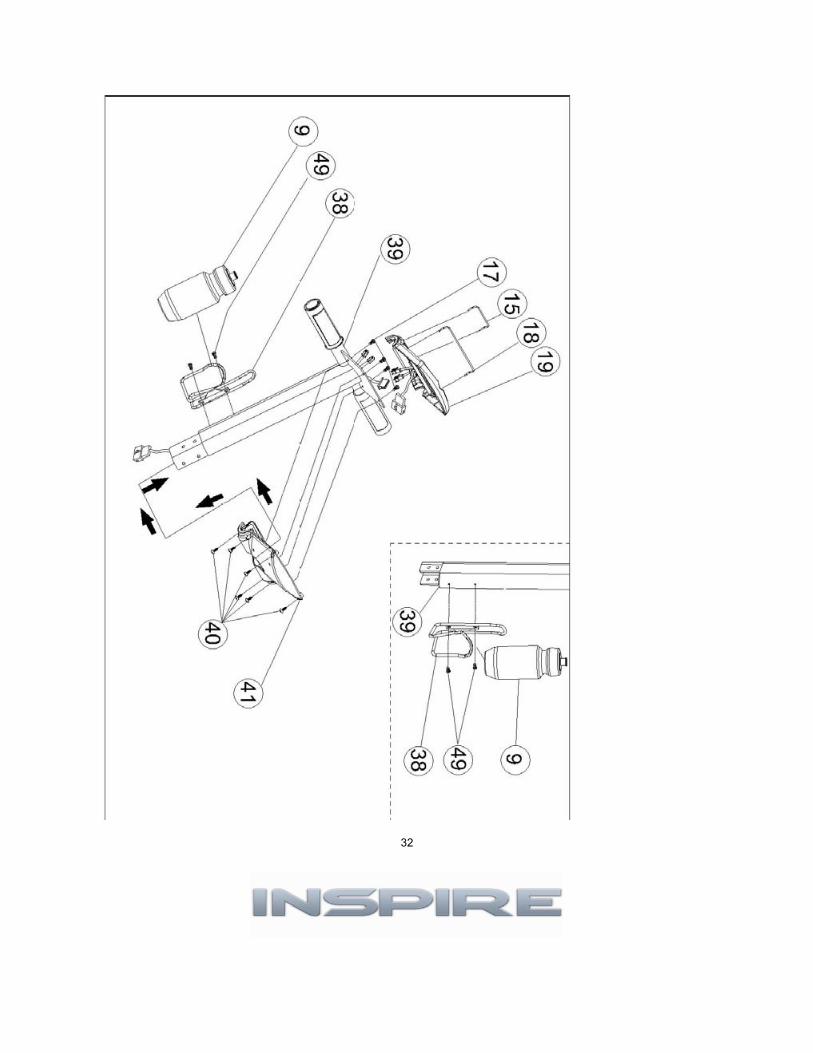
STEP 6: CONSOLE ASSEMBLY (See FIGURE 6)
A.) Wash Water Bottle (#9) thoroughly with warm soapy water. B.) Attach Water Bottle Cage (#38) to Console Assembly using qty 2 Phillips
Head Screws (#49). Slide on Water Bottle (#9). C.) Attach console cable (#37) to mast cable (#85) as shown in FIGURE A. D.) Slide Console Assembly (#39) onto the Main Frame (#34). NOTE: Make
sure not to pinch the cable assembly when assembling the console onto the mounting bracket. E.) Secure Console Assembly (#39) onto the Main Frame (#34) using qty 4 Flat Washers (#33) – flat sides of tube,
qty 2 Curved Washers (#29) – curved front of tube, qty 6 Lock Washers (#32), and qty 6 M8x16mm Screws (#31).
F.) Remove protective film from Console button overlay. G.) Insert the Power Adapter (#130) into the Rear Power Input Connector on Main Frame as shown in FIGURE B. Plug Power Adapter into power source.
Computer LCD should turn on and sound a long beep.
FINAL STEP
Unscrew levelers on Front Stabilizer Assembly (#62) so that both sit flat on the ground. An additional leveler under the frame center tube may be unscrewed to add support in the center of the unit.
16
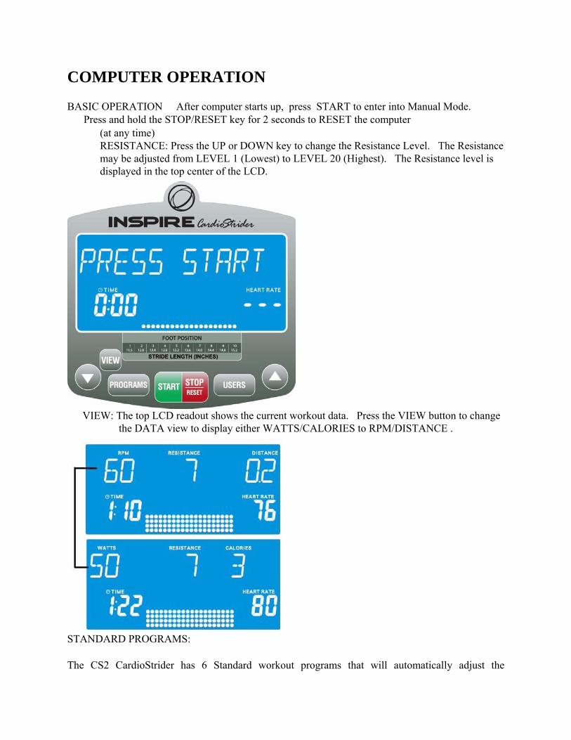
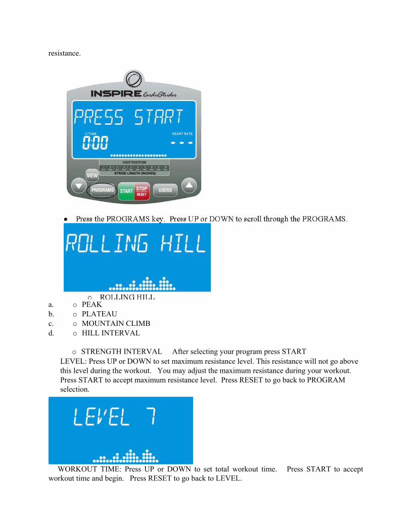
COMPUTER OPERATION
BASIC OPERATION � After computer starts up, press START to enter into Manual Mode. � Press and hold the STOP/RESET key for 2 seconds to RESET the computer
(at any time) � RESISTANCE: Press the UP or DOWN key to change the Resistance Level. The Resistance
may be adjusted from LEVEL 1 (Lowest) to LEVEL 20 (Highest). The Resistance level is displayed in the top center of the LCD.
� VIEW: The top LCD readout shows the current workout data. Press the VIEW button to change
the DATA view to display either WATTS/CALORIES to RPM/DISTANCE .
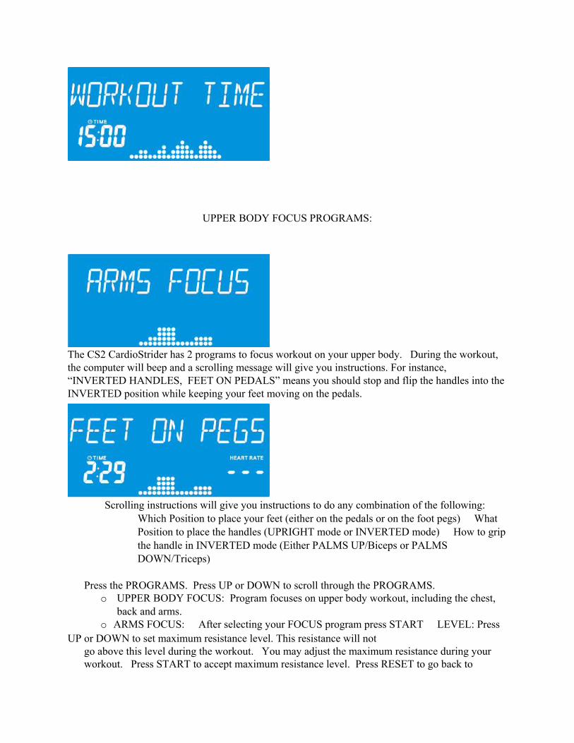
STANDARD PROGRAMS:
The CS2 CardioStrider has 6 Standard workout programs that will automatically adjust the
resistance.
a. o PEAK b. o PLATEAU c. o MOUNTAIN CLIMB d. o HILL INTERVAL
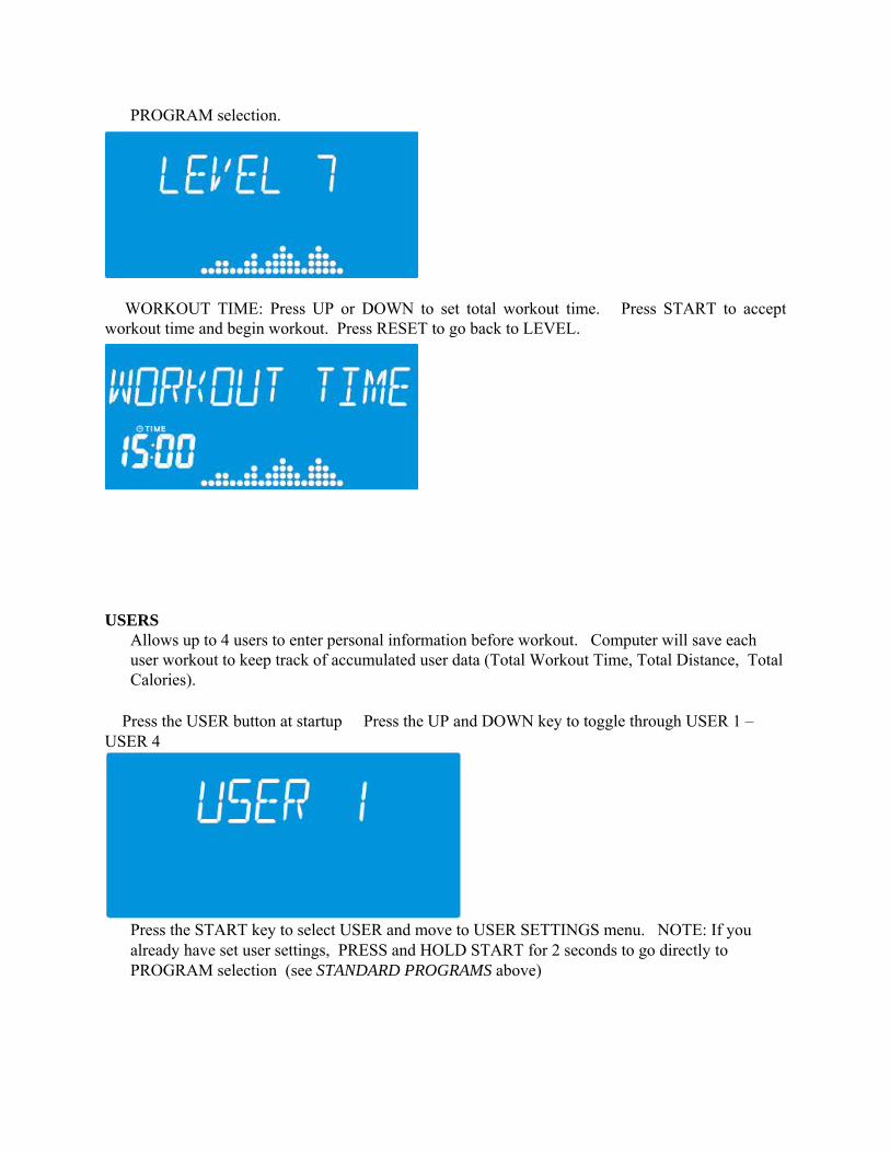
o STRENGTH INTERVAL � After selecting your program press START � LEVEL: Press UP or DOWN to set maximum resistance level. This resistance will not go above
this level during the workout. You may adjust the maximum resistance during your workout. Press START to accept maximum resistance level. Press RESET to go back to PROGRAM selection.
� WORKOUT TIME: Press UP or DOWN to set total workout time. Press START to accept workout time and begin. Press RESET to go back to LEVEL.
UPPER BODY FOCUS PROGRAMS:
The CS2 CardioStrider has 2 programs to focus workout on your upper body. During the workout, the computer will beep and a scrolling message will give you instructions. For instance, “INVERTED HANDLES, FEET ON PEDALS” means you should stop and flip the handles into the INVERTED position while keeping your feet moving on the pedals.
Scrolling instructions will give you instructions to do any combination of the following: �
Which Position to place your feet (either on the pedals or on the foot pegs) � What Position to place the handles (UPRIGHT mode or INVERTED mode) � How to grip the handle in INVERTED mode (Either PALMS UP/Biceps or PALMS DOWN/Triceps)
� Press the PROGRAMS. Press UP or DOWN to scroll through the PROGRAMS. o UPPER BODY FOCUS: Program focuses on upper body workout, including the chest,
back and arms. o ARMS FOCUS: � After selecting your FOCUS program press START � LEVEL: Press
UP or DOWN to set maximum resistance level. This resistance will not go above this level during the workout. You may adjust the maximum resistance during your workout. Press START to accept maximum resistance level. Press RESET to go back to
PROGRAM selection.
� WORKOUT TIME: Press UP or DOWN to set total workout time. Press START to accept workout time and begin workout. Press RESET to go back to LEVEL.
USERS Allows up to 4 users to enter personal information before workout. Computer will save each user workout to keep track of accumulated user data (Total Workout Time, Total Distance, Total Calories).
� Press the USER button at startup � Press the UP and DOWN key to toggle through USER 1 – USER 4
� Press the START key to select USER and move to USER SETTINGS menu. NOTE: If you
already have set user settings, PRESS and HOLD START for 2 seconds to go directly to PROGRAM selection (see STANDARD PROGRAMS above)

USER SETTINGS � Press the UP and DOWN key to toggle between CHANGE USER SETTINGS and
ACCUMULATED USER DATA � Press START to make selection
CHANGE USER DATA
� GENDER: Scrolling message reads “ENTER GENDER” 1 time, then displays “FEMALE” Press the UP or DOWN buttons to toggle between FEMALE and MALE. Press START to accept setting and move to AGE. Press RESET to go back to CHANGE USER SETTINGS.
� AGE: Scrolling message reads “AGE 40”, Press the UP or DOWN key to adjust the AGE value
in 1 year increments. Press START to accept setting and move to WEIGHT. Press RESET to go back GENDER.
� WEIGHT: Scrolling message reads “ENTER WEIGHT” 1 time and then 175 lbs is displayed.
Press the UP or DOWN key to adjust the WEIGHT value in 5 lb increments. Press RESET to go back to AGE.

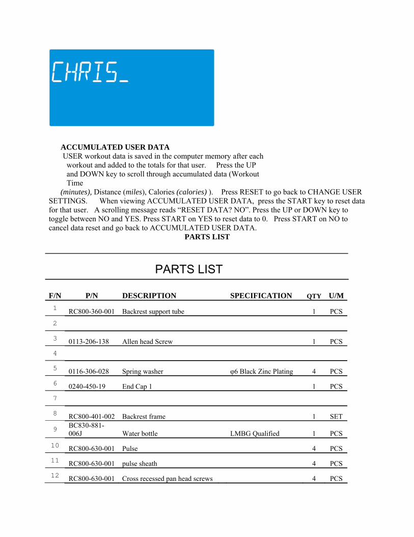
� CHANGE NAME: Scrolling message reads “CHANGE NAME?” 1 time and then “NO” is displayed on the scrolling message . Press the UP or DOWN key to toggle between “YES” and “NO”.
a. o Press START on “YES” to MODIFY CURRENT USER NAME. b. o Press the UP or DOWN key to scroll through 36 alpha-numeric characters (26 letters A-Z, 10 numbers 0-9) and 1 blank space. c. o Press the START key to accept alpha-numeric character and move to next space. If START is pressed before either UP or DOWN is pressed, a BLANK space is used in that location. d. o Press the RESET key to move back to the previous location. e. o A blinking underscore (“_”) is used to show the current location. f. o A Maximum of 8 alpha-numeric characters may be used. g. o After pressing START past at 8
th
space, USER NAME is set. h. o START may be pressed at any time for 2 seconds to set the USER NAME and go to PROGRAM selection.
ACCUMULATED USER DATA
� USER workout data is saved in the computer memory after each workout and added to the totals for that user. � Press the UP and DOWN key to scroll through accumulated data (Workout Time
(minutes), Distance (miles), Calories (calories) ).� Press RESET to go back to CHANGE USER SETTINGS. � When viewing ACCUMULATED USER DATA, press the START key to reset data for that user. A scrolling message reads “RESET DATA? NO”. Press the UP or DOWN key to toggle between NO and YES. Press START on YES to reset data to 0. Press START on NO to cancel data reset and go back to ACCUMULATED USER DATA.
PARTS LIST
PARTS LIST
F/N P/N DESCRIPTION SPECIFICATION QTY U/M 1 RC800-360-001 Backrest support tube 1 PCS 2 3 0113-206-138 Allen head Screw 1 PCS 4 5 0116-306-028 Spring washer φ6 Black Zinc Plating 4 PCS 6 0240-450-19 End Cap 1 1 PCS 7 8 RC800-401-002 Backrest frame 1 SET
9 BC830-881-006J Water bottle LMBG Qualified 1 PCS
10 RC800-630-001 Pulse 4 PCS 11 RC800-630-001 pulse sheath 4 PCS 12 RC800-630-001 Cross recessed pan head screws 4 PCS
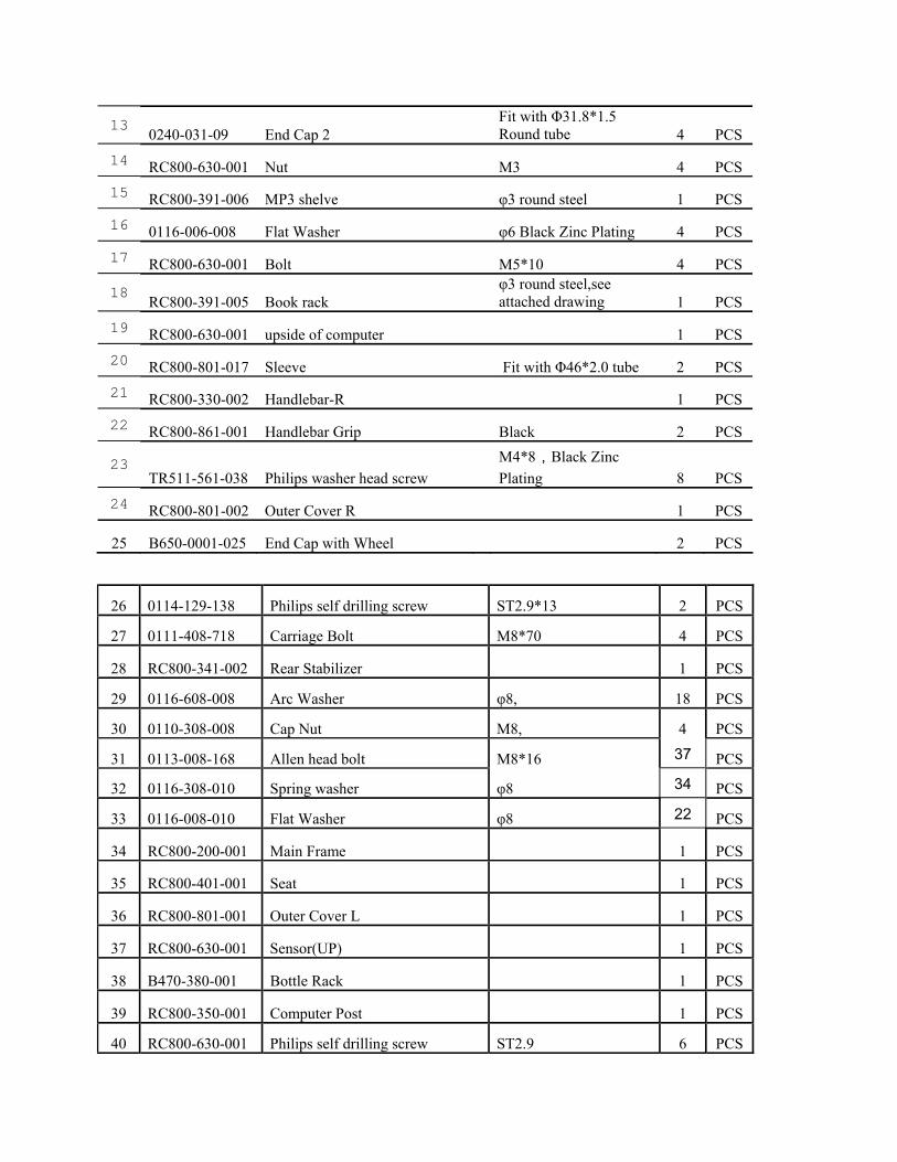
13 0240-031-09 End Cap 2 Fit with Φ31.8*1.5 Round tube 4 PCS
14 RC800-630-001 Nut M3 4 PCS 15 RC800-391-006 MP3 shelve φ3 round steel 1 PCS 16 0116-006-008 Flat Washer φ6 Black Zinc Plating 4 PCS 17 RC800-630-001 Bolt M5*10 4 PCS
18 RC800-391-005 Book rack φ3 round steel,see attached drawing 1 PCS
19 RC800-630-001 upside of computer 1 PCS 20 RC800-801-017 Sleeve Fit with Φ46*2.0 tube 2 PCS 21 RC800-330-002 Handlebar-R 1 PCS 22 RC800-861-001 Handlebar Grip Black 2 PCS
23 TR511-561-038 Philips washer head screw
M4*8,Black Zinc Plating 8 PCS
24 RC800-801-002 Outer Cover R 1 PCS
25 B650-0001-025 End Cap with Wheel 2 PCS
26 0114-129-138 Philips self drilling screw ST2.9*13 2 PCS
27 0111-408-718 Carriage Bolt M8*70 4 PCS
28 RC800-341-002 Rear Stabilizer 1 PCS
29 0116-608-008 Arc Washer φ8, 18 PCS
30 0110-308-008 Cap Nut M8, 4 PCS
31 0113-008-168 Allen head bolt M8*16 37 PCS
32 0116-308-010 Spring washer φ8 34 PCS
33 0116-008-010 Flat Washer φ8 22 PCS
34 RC800-200-001 Main Frame 1 PCS
35 RC800-401-001 Seat 1 PCS
36 RC800-801-001 Outer Cover L 1 PCS
37 RC800-630-001 Sensor(UP) 1 PCS
38 B470-380-001 Bottle Rack 1 PCS
39 RC800-350-001 Computer Post 1 PCS
40 RC800-630-001 Philips self drilling screw ST2.9 6 PCS
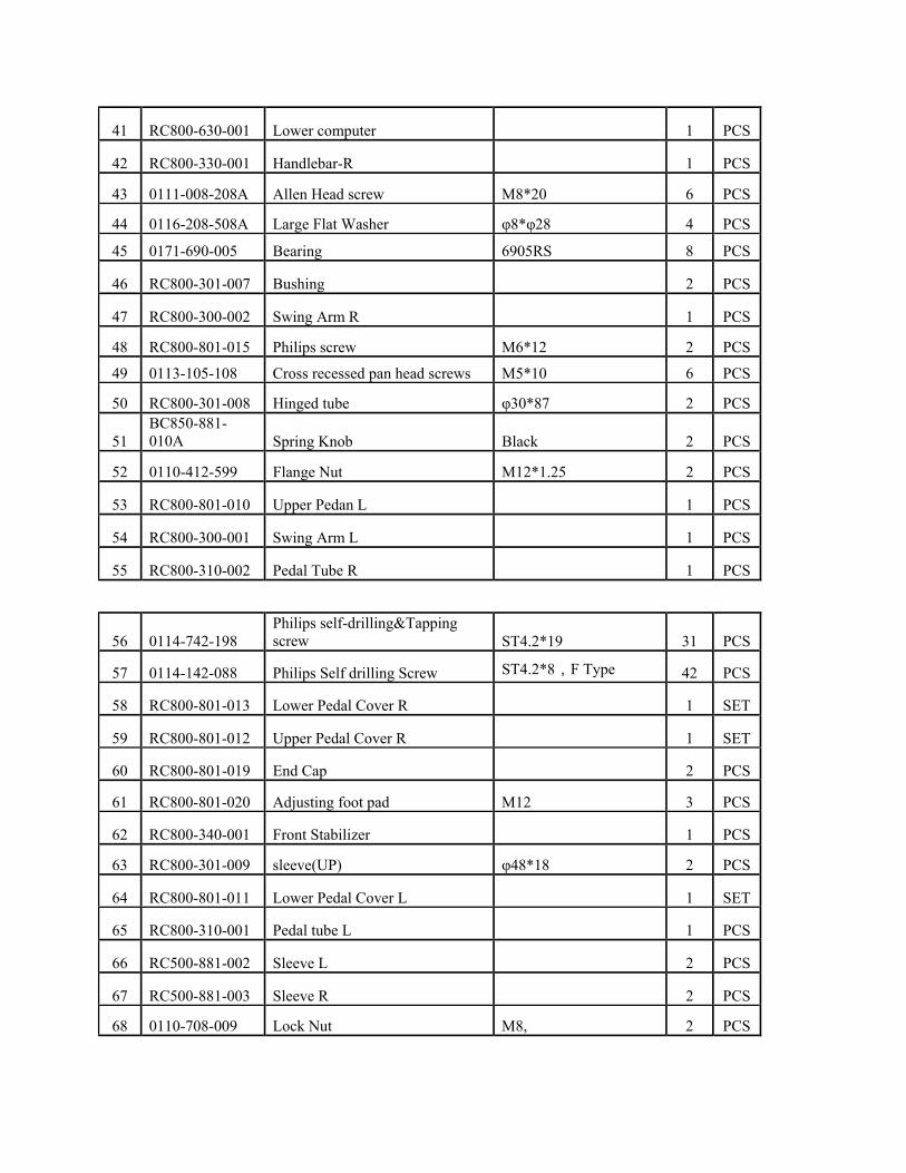
41 RC800-630-001 Lower computer 1 PCS
42 RC800-330-001 Handlebar-R 1 PCS
43 0111-008-208A Allen Head screw M8*20 6 PCS
44 0116-208-508A Large Flat Washer φ8*φ28 4 PCS
45 0171-690-005 Bearing 6905RS 8 PCS
46 RC800-301-007 Bushing 2 PCS
47 RC800-300-002 Swing Arm R 1 PCS
48 RC800-801-015 Philips screw M6*12 2 PCS
49 0113-105-108 Cross recessed pan head screws M5*10 6 PCS
50 RC800-301-008 Hinged tube φ30*87 2 PCS
51 BC850-881-010A Spring Knob Black 2 PCS
52 0110-412-599 Flange Nut M12*1.25 2 PCS
53 RC800-801-010 Upper Pedan L 1 PCS
54 RC800-300-001 Swing Arm L 1 PCS
55 RC800-310-002 Pedal Tube R 1 PCS
56 0114-742-198 Philips self-drilling&Tapping screw ST4.2*19 31 PCS
57 0114-142-088 Philips Self drilling Screw ST4.2*8,F Type 42 PCS
58 RC800-801-013 Lower Pedal Cover R 1 SET
59 RC800-801-012 Upper Pedal Cover R 1 SET
60 RC800-801-019 End Cap 2 PCS
61 RC800-801-020 Adjusting foot pad M12 3 PCS
62 RC800-340-001 Front Stabilizer 1 PCS
63 RC800-301-009 sleeve(UP) φ48*18 2 PCS
64 RC800-801-011 Lower Pedal Cover L 1 SET
65 RC800-310-001 Pedal tube L 1 PCS
66 RC500-881-002 Sleeve L 2 PCS
67 RC500-881-003 Sleeve R 2 PCS
68 0110-708-009 Lock Nut M8, 2 PCS
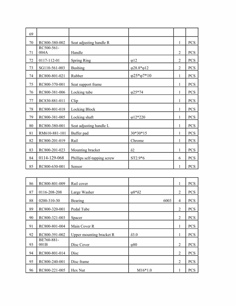
69
70 RC800-380-002 Seat adjusting handle R 1 PCS
71 RC500-561-004A Handle
2 PCS
72 0117-112-01 Spring Ring φ12 2 PCS
73 SG110-561-003 Bushing φ28.8*φ12 2 PCS
74 RC800-801-021 Rubber φ25*φ7*10 1 PCS
75 RC800-370-001 Seat support frame 1 PCS
76 RC800-381-006 Locking tube φ25*74 1 PCS
77 BC830-881-011 Clip 1 PCS
78 RC800-801-018 Locking Block 1 PCS
79 RC800-381-005 Locking shaft φ12*220 1 PCS
80 RC800-380-001 Seat adjusting handle L 1 PCS
81 RM610-881-101 Buffer pad 30*30*15 1 PCS
82 RC800-201-019 Rail Chrome 1 PCS
83 RC800-201-023 Mounting bracket δ2 1 PCS
84 0114-129-068 Phillips self-tapping screw ST2.9*6 6 PCS
85 RC800-630-001 Sensor 1 PCS
86 RC800-801-009 Rail cover 1 PCS
87 0116-208-208 Large Washer φ8*δ2 2 PCS
88 0200-310-30 Bearing 6003 4 PCS
89 RC800-320-001 Pedal Tube 2 PCS
90 RC800-321-003 Spacer 2 PCS
91 RC800-801-004 Main Cover R 1 PCS
92 RC800-391-002 Upper mounting bracket R δ3.0 1 PCS
93 BE760-881-001B Disc Cover φ80
2 PCS
94 RC800-801-014 Disc 2 PCS
95 RC800-240-001 Disc frame 2 PCS
96 RC800-221-005 Hex Nut M16*1.0 1 PCS
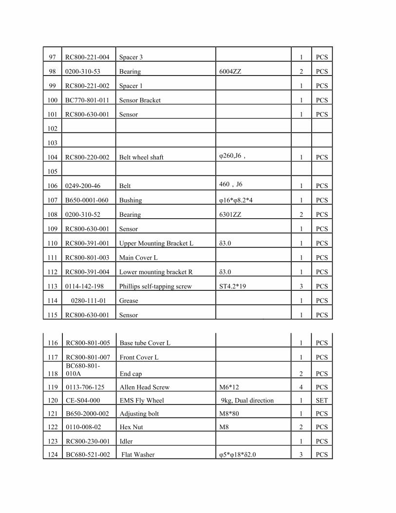
97 RC800-221-004 Spacer 3 1 PCS
98 0200-310-53 Bearing 6004ZZ 2 PCS
99 RC800-221-002 Spacer 1 1 PCS
100 BC770-801-011 Sensor Bracket 1 PCS
101 RC800-630-001 Sensor 1 PCS
102
103
104 RC800-220-002 Belt wheel shaft φ260,J6, 1 PCS
105
106 0249-200-46 Belt 460,J6 1 PCS
107 B650-0001-060 Bushing φ16*φ8.2*4 1 PCS
108 0200-310-52 Bearing 6301ZZ 2 PCS
109 RC800-630-001 Sensor 1 PCS
110 RC800-391-001 Upper Mounting Bracket L δ3.0 1 PCS
111 RC800-801-003 Main Cover L 1 PCS
112 RC800-391-004 Lower mounting bracket R δ3.0 1 PCS
113 0114-142-198 Phillips self-tapping screw ST4.2*19 3 PCS
114 0280-111-01 Grease 1 PCS
115 RC800-630-001 Sensor 1 PCS
116 RC800-801-005 Base tube Cover L 1 PCS
117 RC800-801-007 Front Cover L 1 PCS
118 BC680-801-010A End cap 2 PCS
119 0113-706-125 Allen Head Screw M6*12 4 PCS
120 CE-S04-000 EMS Fly Wheel 9kg, Dual direction 1 SET
121 B650-2000-002 Adjusting bolt M8*80 1 PCS
122 0110-008-02 Hex Nut M8 2 PCS
123 RC800-230-001 Idler 1 PCS
124 BC680-521-002 Flat Washer φ5*φ18*δ2.0 3 PCS
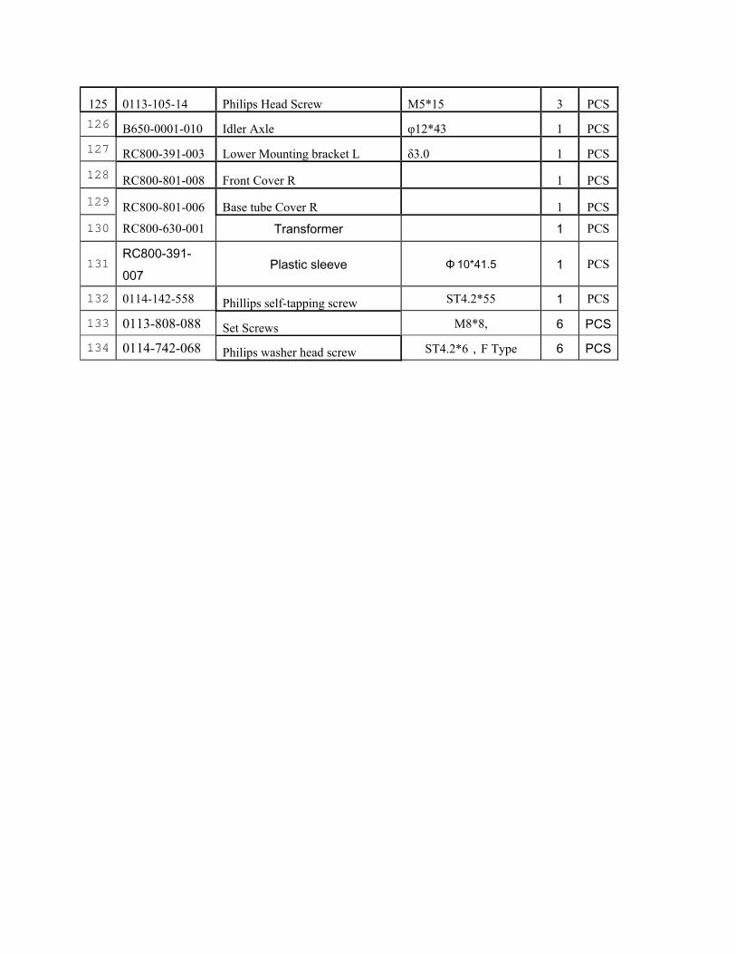
125 0113-105-14 Philips Head Screw M5*15 3 PCS 126 B650-0001-010 Idler Axle φ12*43 1 PCS 127 RC800-391-003 Lower Mounting bracket L δ3.0 1 PCS 128 RC800-801-008 Front Cover R 1 PCS 129 RC800-801-006 Base tube Cover R 1 PCS 130 RC800-630-001 Transformer 1 PCS
131 RC800-391-007
Plastic sleeve Φ 10*41.5 1 PCS
132 0114-142-558 Phillips self-tapping screw ST4.2*55 1 PCS
133 0113-808-088 Set Screws M8*8, 6 PCS
134 0114-742-068 Philips washer head screw ST4.2*6,F Type 6 PCS
32
Warranty This Warranty applies to Inspire Strength products manufactured or distributed by FG1 LLC. This Product is NOT intended for LIGHT-COMMERCIAL or HEALTH CLUB use
CONSUMER USE: 10 YEAR FRAME: Includes Main Frame and Welds
3 YEAR PARTS: Excluding Paint and Finish (unless defective out of box)
1 YEAR LABOR
FG1, LLC. warrants that the Product you have purchased for personal, family or household use from FG1 LLC or from an authorized FG1 reseller is free from defects in materials or workmanship under normal use during the warranty period. Your sales receipt, showing the date of purchase of the Product, is your proof of the date of purchase. This warranty extends only to you, the original purchaser. It is not transferable to anyone who subsequently purchases the Product from you. It excludes expendable parts such as paint and finish. This Warranty becomes VALID ONLY if the Product is assembled / installed according to the instructions / directions included with the Product.
Replacement and repair of parts. During the warranty period FG1 will, at no additional charge, repair or replace the Product if it becomes defective, malfunctions, or otherwise fails to conform with this Warranty under normal personal, family, or household use. In repairing the product FG1 may replace defective parts with, at the option of FG1, serviceable used parts that are equivalent to new parts in performance, or new parts. All exchanged parts and Products replaced under this warranty will become the property of FG1. FG1 reserves the right to change manufacturers and or specification of any part to cover any existing warranty.
Service procedures. To obtain warranty parts, you must return the parts to FG1 or an authorized FG1 retailer in its original container (or equivalent). You must pre-pay any shipping charges, taxes, or any other charges associated with transportation of the Product. In addition, you are responsible for insuring any Product shipped or returned. You assume the risk of loss during shipment. You must present FG1 with proof-of-purchase documents (including the date of purchase, Model, and Serial Number). Any evidence of alteration, erasing or forgery of proof -of-purchase documents will be cause to void this Warranty. Register your warranty online visit www.inspirefitness.net
Conditions and Exceptions. This Warranty does not extend to any Product not purchased from FG1 LLC or from an authorized FG1 reseller. This Warranty does not extend to any Product that has been damaged or rendered defective; (a) as a result of accident, misuse, or abuse; (b) by the use of parts not manufactured or sold by FG1; (c) by modification of the Product; (d) as a result of service by anyone other than FG1, or an authorized FG1 warranty service provider; (e) product that has not been properly maintained (follow maintenance schedule found on product). Should any product submitted for Warranty service be found to be ineligible, an estimate of repair cost will be furnished and the repair will be made if requested by you upon FG1 receipt of payment or acceptable arrangement of payment.
Disclaimer EXCEPT AS EXPRESSLY SET FORTH IN THIS WARRANTY FG1 MAKES NO OTHER WARRANTIES; EXPRESSED OR IMPLIED INCLUDING ANY IMPLIED WARRANTIES OF MERCHANTABILITY AND FITNESS FOR A PARTICULAR PURPOSE. FG1, LLC. EXPRESSLY DISCLAIMS ALL WARRANTIES NOT STATED IN THIS WARRANTY. ANY IMPLIED WARRANTIES THAT MAY BE IMPOSED BY LAW ARE LIMITED TO THE TERMS OF THIS WARRANTY. NEITHER FG1 NOR ANY OF ITS AFFILIATES SHALL BE RESPONSIBLE FOR INCIDENTAL OR CONSEQUENTIAL DAMAGES. FG1 IS NOT RESPOSIBLE FOR THE REPAIR OR REPLACEMENT OF ANY PARTS THAT FG1 DETERMINES HAVE BEEN SUBJECTED AFTER THE DATE OF MANUFACTURE TO ALTERATION, NEGLECT, ABUSE, MISUSE, NORMAL WEAR & TEAR, ACCIDENT, DAMAGE DURING TRANSIT OR INSTALLATION, FIRE, FLOOD, OR ANY ACT OF GOD. SOME STATES DO NOT ALLOW LIMITATIONS ON HOW LONG AN IMPLIED WARRANTY LASTS OR THE EXCLUSION OR LIMITATION OF INCIDENTAL OR CONSEQUENTIAL DAMAGES, SO THE ABOVE LIMITATIONS OR EXCLUSION MAY NOT APPLY TO YOU. This Warranty gives you specific legal rights and you may also have other rights that may vary from state to state. This is the only express warranty applicable to FG1’s “Inspire” branded strength products. FG1 neither assumes nor authorizes anyone to assume for it any other express warranty.
33