
TABLE OF CONTENTS - India’s Premier Educational … OF CONTENTS 1. Syllabus ... Load test on DC...
76
TABLE OF CONTENTS 1. Syllabus 2. Mapping of Program Outcomes with Instructional Objectives 3. Mapping of Program Educational Objectives with Program Outcomes 4. Session plan 5. Laboratory policies & Report format. 6. Evaluation sheet 7. Each experiment should be prefixed with prelab questions with answer key and suffixed with post lab questions with answer key. 8. Projects. 1
Transcript of TABLE OF CONTENTS - India’s Premier Educational … OF CONTENTS 1. Syllabus ... Load test on DC...

TABLE OF CONTENTS
1. Syllabus
2. Mapping of Program Outcomes with Instructional Objectives
3. Mapping of Program Educational Objectives with Program Outcomes
4. Session plan
5. Laboratory policies & Report format.
6. Evaluation sheet
7. Each experiment should be prefixed with prelab questions
with answer key and suffixed with post lab questions with
answer key.
8. Projects.
1

Syllabus 2

L T P C
EE 0209 ELECTRICAL MACHINES LAB - I 0 0 3 2
Prerequisite
EE 0201
PURPOSE
To give students a fair knowledge of testing different types of DC machines and transformers.
INSTRUCTIONAL OBJECTIVES At the end of the course the students will be able to:
1. Understand the performance and characteristics of DC machines and transformers.
2. Understand the testing of DC machines and transformers.
LIST OF EXPERIMENTS
1. Load test on DC shunt motor
2. Load test on DC Series motor
3. Speed Control of DC Shunt Motor.
4. Load test on DC shunt generator, DC compound generator.
5. Load test on single phase transformer.
6. Open circuit & Short circuit test on single phase transformer
7. Open circuit characteristics of DC generator (Self and Separately Excited)
8. Swinburne’s test and separation of losses in DC Machine.
9. Hopkinson’s test
10. Sumpner’s test on 1-phase transformers
11. 3-phase transformer connections
12. 3-phase to 2 -phase conversion
3

REFERENCE
Laboratory manual.
EE 0209 - ELECTRICAL MACHINES LAB - I (R) 1
2
Course designed by
Student outcomes
Department of Electrical and Electronics Engineering
a b c d e f g h i j k
x x x
Engineering
Basic Sciences
Category
3
Broad area (for ‘P’category)
General (G)
Electrical
Machines
x
Sciences and
(B) Technical
Arts(E)
Circuits Electronics
and
Systems
Professional Subjects(P)
x
Power Intelligent
System Systems
4 Course Coordinator Mrs. P.Sivasankari
4

Mapping of Program
Outcomes with Instructional
Objectives 5

Mapping of Program Instructional Objectives Vs Program Outcomes
Program Outcomes
Understand the Understand the
performance and testing of DC
characteristics of DC machines and
machines and transformers.
transformers.
a).An ability to apply x
knowledge of mathematics,
science, and engineering.
b). An ability to design and x x
conduct experiments, as
well as to analyze and
interpret results. e).An ability to identify, x
formulate, and solve engineering problems
6

Mapping of Program
Educational Objectives with
Program Outcomes 7

PROGRAM EDUCATIONAL
CRITERION 3 (a-k OUTCOMES) OBJECTIVES
1 2 3 4
(a) an ability to apply knowledge of X
mathematics, science, and engineering
(b) an ability to design and conduct X
experiments, as well as to analyze and
interpret data
(c) an ability to design a system, component, X
or process to meet desired needs within
realistic constraints such as economic,
environmental, social, political, ethical,
health and safety, manufacturability, and
sustainability
(d) an ability to function on multidisciplinary X X
teams
(e) an ability to identify, formulate, and X
solve engineering problems
(f) an understanding of professional and X
ethical responsibility
(g) an ability to communicate effectively in X
both verbal and written form.
(h) the broad education necessary to X
understand the impact of engineering
solutions in a global perspective.
(i) a recognition of the need for, and an X
ability to engage in life-long learning
(j) a knowledge of contemporary issues X
(k) an ability to use the techniques, skills, X X
and modern engineering tools necessary for
engineering practice.
8

Academic Course Description
SRM University, Kattankulathur
Faculty of Engineering and Technology
Department of Electrical and Electronics Engineering
COURSE : EE0209
TITLE : ELECTRICAL MACHINES LAB I
CREDIT : 01
LOCATION : DC Machines Lab
PREREQUISITES COURSES : EE0201-Electrical Machines - I
PREREQUISITIES BY TOPIC : NIL
Outcomes
Students who have successfully completed this course
Instructional Objective
The students will be able to:
Understand the performance and characteristics of DC
machines and transformers.
Understand the testing of DC machines and transformers
Program outcome
a) An ability to apply
knowledge of mathematics,
science, and engineering.
b) An ability to design and
conduct experiments, as
well as to analyze and
interpret data.
e) An ability to identify,
formulates, and solves
engineering problems.
9

Text book(s) and/or required materials:
1. B.L.THERAJA & A.K.THERAJA , vol II AC & DC
machines.
2. Electrical machines, Nagrath & kothari
3. Electrical machines lab I Manual
4. Electrical machines lab reference manual
Web Resources:
1. www.ncert.nic.in 2. www.electricalmachine.net
Professional component:
General
Basic Sciences
Engineering sciences & Technical arts
Professional subject
SESSION PLAN:
WEEK NAME OF THE
EXPERIMENT
I Load test on DC shunt motor
II Load test on DC Series motor
III Speed Control of DC Shunt
Motor.
IV Load test on DC shunt generator,
DC compound generator.
V Load test on single phase
transformer.
VI Open circuit & Short circuit test
on single phase transformer
VII open circuit characteristics of DC
generator (Self and Separately
Excited)
- 0%
- 0%
- 0%
- 100%
REFERENCE
1.B.L.THERAJA &
A.K.THERAJA , vol
II AC & DC
machines.
2.Electrical
machines lab I
Reference manual
OBJECTIVE
Understand the
performance and
characteristics of DC
machines and
transformers
10

VIII Swinburne’s test and separation of
losses in DC Machine.
IX Hopkinson’s test
X Sumpner’s test on 1-phase
transformers
XI 3-phase transformer connections
XII 3-phase to 2 -phase conversion
Understand the testing
of DC machines and
transformers
Understand the
performance and
characteristics of DC
machines and
transformers
Course Learning Outcome:
This course provides the foundation
education in electric circuit analysis and
design. Through lecture, laboratory, and
out-of-class assignments, students are
provided learning experience that enable
them to:
1. Understand the performance and
characteristics of DC machines and
transformers
2. Understand the testing of DC machines
and transformers
Correlates to
program outcome
H M L
H
H
H: high correlation, M: medium correlation, L: low correlation
11

EVALUVATION METHOD:
• Prelab Test - 10%
• Inlab Performance - 30%
• Postlab Test - 10%
• Attentance - 5%
• Record - 20%
• Final Exam - 25%
• Total - 100%
LABORATORY POLICIES AND REPORT FORMAT:
1. Lab reports should be submitted on A4 paper. Your report is a professional
presentation of your work in the lab. Neatness, organization, and completeness will be
rewarded. Points will be deducted for any part that is not clear.
2. The lab reports will be written individually. Please use the following format for your
lab reports.
a. Cover Page: Include your name, Subject Code, Subject title, Name
of the university.
b. Evaluation Sheet: Gives your internal mark split -up.
c. Index Sheet: Includes the name of all the experiments.
d. Experiment documentation: It includes experiment name, date,
objective,circuit diagram, simulated circuit and verified outputs.
e. Prelab and Postlab question should be retyped in the end of every
cycle.
3. Your work must be original and prepared independently. However, if you need any
guidance or have any questions or problems, please do not hesitate to approach your
staff incharge during office hours. The students should follow the dress code in the
Lab session.
4. Labs will be graded as per the following grading policy:
• Prelab Test - 10%
• Inlab Performance - 30%
• Postlab Test - 10%
• Attentance - 5%
• Record - 20%
• Final Exam - 25%
• Total - 100%
12

5. Reports Due Dates: Reports should be submitted at the end of each cycle. A late lab report
will have 20% of the points deducted for being one day late. If a report is 2 days late, a grade of 0
will be assigned.
6. Systems of Tests: Regular laboratory class work over the full semester will carry a
weightage of 75%. The remaining 25% weightage will be given by conducting an end
semester practical examination for every individual student if possible or by conducting a
1 to 1 ½ hours duration common written test for all students, based on all the experiment carried
out in the semester.
Prelab test is conducted at the beginning of each cycle as a written test and the post lab test
is conducted as viva-voce during the permission of report.
13

Pre-lab Questions 1. What is the working principle of generator?
2. What do you mean by Shunt Generator?
.
3. Write the EMF Equation of the Generator?
4. How may the number of parallel paths in an armature be increased?
5. How should a generator be started?
14

OPEN CIRCUIT AND LOAD CHARACTERISTICS OF DC SHUNT
GENERATOR
Aim:
To perform open circuit test and load test on the given DC shunt generator and to draw its
characteristics curves.
Apparatus Required:
S.No. Apparatus Range Type Quantity
1 Ammeter (0-1)A MC 1
2 Voltmeter (0-300)V MC 1
3 Rheostats 1250Ω, 0.8A Wire Wound 2
4 SPST Switch - - 1
5 Tachometer (0-1500)rpm Digital 1
6 Connecting Wires 2.5sq.mm. Copper Few
Precautions:
1. The field rheostat of motor should be in minimum resistance position at the time of
starting and stopping the machine.
2. The field rheostat of generator should be in maximum resistance position at the time
of starting and stopping the machine.
3. SPST switch is kept open during starting and stopping.
Procedure:
1. Connections are made as per the circuit diagram.
2. After checking minimum position of motor field rheostat, maximum position of
generator field rheostat, DPST switch is closed and starting resistance is gradually
removed.
3. By adjusting the field rheostat, the motor is brought to rated speed.
4. Voltmeter and ammeter readings are taken when the SPST switch is kept open.
5. After closing the SPST switch, by varying the generator field rheostat, voltmeter and
ammeter readings are taken.
15

6. After bringing the generator rheostat to maximum position, field rheostat of motor to
minimum position, SPST switch is opened and DPST switch is opened.
Formulate Used
1. Ia = Ir + IL
2. Eg = Ia Ra + VL
Tabular Column:
S.No. Ir (Amp) Eg (Volts)

Eo (
Volt
s)
Load Test
Sl.No. VL Ir IL Ia EG
(Volts) (Amp) (Amp) (Amp) (Volts)
Model Graph:
Critical Resistance = Eo / If Ohms
If
Eo
If (Amps)
Result:
Thus open circuit characteristics of self excited DC shunt generator are obtained and its critical
resistance is determined.
17

Post lab questions 1. What causes heating of armature?
2. How do we conclude theat connections between field coils and armature are correct?
3. When a generator loses its residual magnetism either due to lighting or short circuit ,how can it
be made to build up?
4.What are the causes of hot bearings?
5. Will a generator build up if it becomes reversed?
18

LOAD CHARACTERISTICS OF DC COMPOUND GENERATOR
Pre- Lab Questions:
1. How should a compound generator be started?
2. What in meant by build up of generator?
3. What is the procedure for shutting down a generator?
4. What is meant by armature reaction?
.
5. How are brushes connected in a dc generator?
19

LOAD CHARACTERISTICS OF DC COMPOUND GENERATOR
Aim:
To conduct a load test and to draw the external (or) load characteristics of the given
compound generator when it is,
(i) Cumulatively compounded
(ii) Differentially compounded
Apparatus Required:
S.No. Apparatus Range Type Quantity
(0-2)A MC 1 1 Ammeter
(0-20) A MC 1
2 Voltmeter (0-300)V MC 1
3 Rheostats 1200Ω, 0.8A Wire Wound 2
4 Loading Rheostat 5KW, 230V - 1
5 Tachometer (0-1500)rpm Digital 1
6 Connecting Wires 2.5sq.mm. Copper Few
Precautions:
1. The field rheostat of motor should be at minimum position.
2. The field rheostat of generator should be at maximum position.
3. No load should be connected to generator at the time of starting and stopping.
Procedure:
1. Connections are made as per the circuit diagram.
2. After checking minimum position of DC shunt motor field rheostat and maximum
position of DC shunt generator field rheostat, DPST switch is closed and starting
resistance is gradually removed.
3. Under no load condition, Ammeter and Voltmeter readings are noted, after
bringing the voltage to rated voltage by adjusting the field rheostat of generator.
4. Load is varied gradually and for each load, voltmeter and ammeter readings are
noted.
20

5. Then the generator is unloaded and the field rheostat of DC shunt generator is
brought to maximum position and the field rheostat of DC shunt motor to
minimum position, DPST switch is opened.
6. The connections of series field windings are reversed the above steps are
repeated.
7. The values of voltage for the particular currents are compared and then the
differential and cumulative compounded DC generator is concluded accordingly.
Tabular Column
Cumulative Compound
VL (Volts) IL (Amp)

V (
Volt
s)
Differential Compound
VL (Volts) IL (Amp)
Model Graph:
Cumulatively Compounded
Differentially Compounded
IL (Amps)
Result:
Thus load characteristics of DC compound generator under cumulative and differential mode
condition are obtained.
22

Post Lab questions:
1. What are the indication of an order loaded generator?
2. What are the causes of an overloaded generator?
3. What are the causes for the failure of generator to build up?
23

LOAD TEST ON DC SHUNT MOTOR Pre lab Questions:
1. Define Back EMF?
2. State the voltage equation of motor.
3. What is the condition for maximum power developed in motor?
4. Give an expression for the armature torque of a motor.
5. Give an expression for speed of DC motor
24

LOAD TEST ON DC SHUNT MOTOR
Aim:
To perform the load test on the given DC shunt motor and to draw the performance
characteristics
Apparatus Required:
S.No. Apparatus Range Type Quantity
1 Ammeter (0-20)A MC 1
2 Voltmeter (0-300)V MC 1
3 Rheostat 1250Ω, 0.8A Wire Wound 1
4 Tachometer (0-1500) rpm Digital 1
5 Connecting Wires 2.5sq.mm. Copper Few
Precautions:
1. DC shunt motor should be started and stopped under no load condition.
2. Field rheostat should be kept in the minimum position.
3. Brake drum should be cooled with water when it is under load.
Procedure:
1. Connections are made as per the circuit diagram.
2. After checking the no load condition, and minimum field rheostat position, DPST
switch is closed and starter resistance is gradually removed.
3. The motor is brought to its rated speed by adjusting the field rheostat.
4. Ammeter, Voltmeter readings, speed and spring balance readings are noted under no
load condition.
5. The load is then added to the motor gradually and for each load, voltmeter, ammeter,
spring balance readings and speed of the motor are noted.
6. The motor is then brought to no load condition and field rheostat to minimum
position, then DPST switch is opened.
25

Spee
d N
(rp
m)
Torq
ue
T (
Nm
)
Spee
d N
(rp
m)
Eff
icie
ncy
%
Formulae Used
1. Input power = V x I Watts
2. Torque = (9.81) x (S1 ~ S2) x R, N-m
2∏NT 3.
Output power
4. % efficiency =
Model Graphs:
y3 y2 y1
N
Watts 60
Output power x100% Input power
η
T
Output Power (Watts)
26
y
x
Torque T (Nm)

Tabular Column
Sl V I N Spring Balance Torque Input Output Efficiency
No. Volts Amp Rpm S1 S2 S1-S2 N-m Watts Watts %
Kg Kg Kg
Result:
The load test on the given dc shunt motor was connected and its performance
characteristics were drawn.
27

Post Lab Questions:
1. What will happen if the field of a dc shunt motor is opened?
2. Explain what happens of when dc moor is connected across an AC supply.
3. Why does a dc motor some time spark on light load?
4. What will happen if a shunt motor is directly connected to the supply line?
28

LOAD TEST ON DC SERIES MOTOR
Pre Lab Questions:
1. Explain the motor principle.
2. Define torque.
3. What do you mean by lost torque?
4. Give any two applications of DC series motor.
5. Is DC series motor a constant speed or variable speed motor.
29

LOAD TEST ON DC SERIES MOTOR
Aim:
To perform the load test on the given DC series motor and to plot its performance
characteristics
Apparatus Required:
S.No. Apparatus Range Type Quantity
1 Ammeter (0-20)A MC 1
2 Voltmeter (0-300)V MC 1
(0-3000) 3 Tachometer Digital 1
rpm
4 Connecting Wires 2.5sq.mm. Copper Few
Precautions:
1. The motor should be started and stopped with load
2. Brake drum should be cooled with water when it is under load.
Procedure:
1. Connections are made as per the circuit diagram.
2. After checking the load condition, DPST switch is closed and starter resistance is
gradually removed.
3. For various loads, Voltmeter, Ammeter readings, speed and spring balance readings
are noted.
4. After bringing the load to initial position, DPST switch is opened.
Formulae Used
1. Input power = W x I Watts
2. Torque = (S1 ~ S2)x 9.81 x R N - m
Where R is the radius of the brake drum
Circumference of the brake drum = 73 cm
(2 Π R) R = 0.116 m
2∏NT 3. Output power = Watts
60 Output power
4. Efficiency = x100% Input power
30

Torq
ueT
(Nm
)
Eff
icie
ncy
%
Sp
eed
N(r
pm
)
Tabular Column: Sl V I N Spring Balance Torque Input Output Efficiency
No. Volts Amp Rpm S1 S2 S1-S2 N-m Watts Watts %
Kg Kg Kg
Model Graph:
y3 y2 y1
T
E
N
Output Power
Result:
Thus load test on the DC series motor was conducted and its performance characteristics were
drawn.
31

Post Lab Questions: 1. Why series motor should always be started with some load?
2. What are the operating characteristics of DC series motors?
3. How do you fix the fuse rating of a DC machine?
32

SPEED CONTROL OF DC SHUNT MOTOR
Pre Lab Questions:
1. What are the factors controlling motor speed?
2. Name the various speed control methods flux control method,
3. Define stalling current.
4. What is the necessity of a starter?
33

SPEED CONTROL OF DC SHUNT MOTOR
Aim:
To control the speed of the given DC shunt motor by
a. Field control method
b. Armature control method
Apparatus Required:
S.No. Apparatus Range Type Quantity
1 Ammeter (0-20) A MC 1
2 Voltmeter (0-300) V MC 1
1250Ω, 0.8A Wire 3 Rheostats Each 1
50Ω, 3.5A Wound
4 Tachometer (0-3000) rpm Digital 1
5 Connecting Wires 2.5sq.mm. Copper Few
Precautions:
1. Field Rheostat should be kept in the minimum resistance position at the time of
starting and stopping the motor.
2. Armature Rheostat should be kept in the maximum resistance position at the time of
starting and stopping the motor.
Procedure:
1. Connections are made as per the circuit diagram.
2. After checking the maximum position of armature rheostat and minimum position of
field rheostat, DPST switch is closed
(i) Armature Control:
1. The field current is kept constant and the armature voltage is varied in steps with the
help of armature rheostat and the corresponding speeds are noted down
2. The above procedure is repeated for different values of field current.
(ii) Field Control:
1. Supply is switched ‘ON’ and the motor is started
2. The armature voltage is kept constant and the field current is varied in steps and the
corresponding speeds are noted.
34

3. The above procedure is repeated for different values of armature voltage
Tabular Column:
1. Armature Control Method
Ir1 = 0.8A Ir2 = 0.7A
Sl.No. V N V N
Volts Rpm Volts Rpm
35

Spee
d N
(rp
m)
Spee
d N
(rp
m)
2. Field Control Method
Sl.No. Ir N Ir N
A Rpm A Rpm
Model Graphs:
If1
If2
If3
Va1
Va3 Va2
Va (Volts)
Result:
If (Amps)
The speed of the given dc shunt motor was controlled by armature control method and field
control method, and the speed characteristics were drawn.
36

Post Lab Questions:
1. What are the advantages of field control method?
2. What are merits of rheostatic control method?
37

SWINBURNE’S TEST
Pre Lab Questions:
1. For what kind of machines this test in applicable?
2. What are the advantages of this test?
3. What is the disadvantages of this test?
38

SWINBURNE’S TEST
Aim:
To predetermine the efficiency of DC shunt machine when it acts as a generator and motor.
Apparatus Required:
S.No. Apparatus Range Type Quantity
1 Ammeter (0-20) A MC 1
2 Voltmeter (0-300) V MC 1
Wire 3 Rheostats 1250Ω, 0.8A 1
Wound
4 Tachometer (0-3000) rpm Digital 1
5 Resistive Load 5KW,230V - 1
6 Connecting Wires 2.5sq.mm. Copper Few
Precautions:
The field rheostat should be in the minimum position at the time of starting and stopping
the motor
Procedure:
1. Connections are made as per the circuit diagram.
2. After checking the minimum position of field rheostat, DPST switch is closed and
starting resistance is gradually removed.
3. By adjusting the field rheostat, the machine is brought to its rated speed.
4. The armature current, field current and voltage readings are noted.
5. The field rheostat is then brought to minimum position DPST switch is opened.
Formulae Used
Constant Losses Wc = Input power - Armature copper loss
= V x Io - (Io - Ir)2 x Ra
Where Ra is the resistance of the armature
39

For motor
(i) Ia - IL - If
(ii) Ia2 Ra
(iii) Total loss WT = WC + Ia2 Ra
(iv) Input power = V IL
Input Power − Total loss (v) Efficiency ηm = x100%
Input Power For Generator
(i) Ia - IL - If
(ii) Ia2 Ra
(iii) Total loss WT = WC + Ia2 Ra
(iv) Output power = V IL
Output Power (v) Efficiency ηG = x100%
Input Power +Total Loss
Model Graph:
As a Generator
% η
As a Motor
OUTPUT POWER P0
(W)

Tabular Columns:
V IO Ir
(Volts) (Amp) (Amp)
Motor
IL Ia=IL+Ir Ia2 Ra We WT =We+ Output Input %η A A Watts Watts Ia2 Ra Watts Watts
Watts
Generator
IL Ia=IL+Ir Ia2 Ra We WT =We+ Output Input %η A A Watts Watts Ia2 Ra Watts Watts
Watts
Result:
Thus the efficiency of the D.C shunt machine was predetermined when it is acting as a generator as well
as motor.
41

Post Lab Questions:
1. Why a three point starter is necessary for a DC shunt motor?
2 What is the precaution that should be followed?
3. What is the formula to find the efficiency of DC machine when running as a generator
and as a motor?
42

Pre Lab Questions:
1. What is the other name of Hopkinson’s test?
2. What is the main requirement in conducting Hopkinson’s test?
43

HOPKINSON’S TEST
Aim:
To conduct Hopkinson’s test on the given pair of DC machine and to obtain the
performance characteristics.
Apparatus Required:
S.No. Apparatus
1 Ammeter
2 Voltmeter
3 Rheostats
4 Tachometer
5 Resistive Load
6 Connecting Wires
Range
(0-1)A
(0-20) A
(0-300) V
(0-600)V
1250Ω, 0.8A
(0-3000) rpm
5KW,230V
2.5sq.mm.
Type
MC
MC
MC
MC
Wire
Wound
Digital
-
Copper
Quantity
1
2
1
1
2
1
1
Few
Precautions:
1. The field rheostat of the motor should be in the minimum position at the time of
starting and stopping the machine.
2. The field rheostat of the generator should be in the maximum position at the time
of starting and stopping the machine.
3. SPST switch should be kept open at the time of starting and stopping the machine.
Procedure:
1. Connections are made as per the circuit diagram.
2. After checking the minimum position of field rheostat of motor, maximum
position of field rheostat of generator, opening of SPST switch, DPST switch is
closed and starting resistance is gradually removed.
3. The motor is brought to its rated speed by adjusting the field rheostat of the motor.
4. The voltmeter V1 is made to read zero by adjusting field rheostat of generator and
SPST switch is closed.
5. By adjusting field rheostats of motor and generator, various Ammeter readings,
voltmeter readings are noted.
6. The rheostats and SPST switch are brought to their original positions and DPST
switch is opened.
44

Formulae Used
1. Power drawn from supply = Vs Is
2. Iam = IL + (Is - Ifm)
3. Armature copper loss in motor Iam2 Ram.
Where Ram is armature resistance of motor
4. Shunt field copper loss in generator = Vs Ifm
5. Iag = ILg + Ifg
6. Armature copper loss in generator = Iag2 Rag.
7. Shunt field copper loss in generator = Vs Ifg.
8. Total stray loss of both machines Ws =
Ws=Vs Is -[Iam2 Ram + Vs Ifm + Iag2 Rag +Vs Ifg]
W s
9. Stray loss of generator (or) motor = 2
10. W s
Total loss of motor WT = +Iam2 Ram + Vs Ifm 2
W s 11. Total loss of generator +Iam2 Ram + Vs Ifm
2 12. Output of generator = Vg. ILg
13. Input = Output + Total losses of generator
Output of generator 14. ηg = x100
Input of generator 15. Input of motor = Vs (Is + ILg)
16. Output of motor = Input of motor - Total losses of motor
45

17. ηm =
Output of motor x100 Input of motor
Tabular Column
Vs Is Ifm Vg Ifg ILg
(Volts) (Amp) (Amp) (Volts) (Amp) (Amp)
Generator
ILg Iag2 Ram
Shunt
Copper
Loss
Ws/2 WT
Output
Input
η %
Motor
ILg Iag2 Ram
Shunt
Copper
Loss
Ws/2 WT
Output
Input
η %
Model Graph:
As a Generator
%
As a
OUTPUT POWER P0
Result:
Thus Hopkinson’s test on the given pair of dc machines was conducted and the performance
characteristics were obtained.
46

Post Lab Questions
1. What is the advantages of this test?
2. What is the disadvantage of the test?
3. In rewinding the armature of a dc motor, progressive connections are changed to
retrogressive ones, will it affect the operation in anyway.
4. Why does dc motor some time run too fast when under load?
47

LOAD TEST ON SINGLE PHASE TRANSFORMER
Pre Lab Questions:
1. Define ideal transformer.
Its windings have no Ohmic resistance no magnetic leakage, no I2R and core
losses.
2. Give the transformer principle
Mutual induction.
3. Write the EMF equation of a transformer
E1 = 4.44 of N1 φm
E2 = 4.44 of N2 φm
4. Define voltage transformation ratio?
E N K = 2 2
= E N
1 1
48

LOAD TEST ON A SINGLE PHASE TRANSFORMER
Aim:
To conduct load test on the given single phase transformer and to draw its
characteristics.
Apparatus Required:
S.No. Apparatus
1 Ammeter
2 Voltmeter
3 Wattmeter
Range Type Quantity
(0-10)A MI 1
(0-5) A MI 1
(0-150)V MI 1
(0-300) V MI 1
(300V, 5A) Upf 1
(150V, 5A) Upf 1
4 Auto Transformer 1φ, (0-260)V - 1
5 Resistive Load 5KW, 230V - 1
6 Connecting Wires 2.5sq.mm Copper Few
Precautions:
1. Auto Transformer should be in minimum position.
2. The AC supply is given and removed from the transformer under no load condition.
Procedure:
1. Connections are made as per the circuit diagram.
2. After checking the no load condition, minimum position of auto transformer and
DPST switch is closed.
3. Ammeter, Voltmeter and Wattmeter readings on both primary side and secondary side
are noted.
4. The load is increased and for each load, Voltmeter, Ammeter and Wattmeter readings
on both primary and secondary sides are noted.
5. Again no load condition is obtained and DPST switch is opened.
49

Formulae:
1. % Efficiency η
2. % Regulation =
Tabular Column
Ws x100
Wp
V No load − V Load x100
V No Load
Vp Ip Wp (Watts) Vs Is Ws (Watts) % η %
(Volts) (Amps) OBS ACT (Volts) (Amps) OBS ACT Regulation
50

Eff
icie
ncy
η %
Reg
ula
tion R
%
Model Graphs:
η
R
Output Power (Watts) Result:
The load test on the single phase transformer was conducted and its characteristics
were drawn.
51

Post Lab Questions:
1. Why transformer rating is in KVA?
2. Define regulation of a transformer.
52

OC & SC TEST OF SINGLE PHASE TRANSFORMER Pre
Lab Questions:
1. What is the purpose of this test?
2. On which side of the transformer OC test in conducted?
3. On which side of the transformer SC test in conducted?
53

OPEN CIRCUIT & SHORT CIRCUIT TEST ON A
SINGLE PHASE TRANSFORMER Aim:
To conduct open circuit and short circuit test on the given single phase transformer and to
predetermine the efficiency and regulation of the transformer and also to draw the equivalent
circuit.
Apparatus Required:
S.No. Apparatus
1 Ammeter
2 Voltmeter
3 Wattmeter
4 Connecting Wires
Range Type Quantity
(0-2)A MI 1
(0-5) A MI 1
(0-150)V MI 2
(150V, 5A) LPF 1
(150V, 5A) UPF 1
2.5sq.mm Copper Few
Precautions:
1. Auto Transformer should be in minimum voltage position at the time of closing &
opening DPST Switch.
Procedure:
Open Circuit Test:
1. Connections are made as per the circuit diagram.
2. After checking the minimum position of Autotransformer, DPST switch is closed.
3. Auto transformer variac is adjusted get the rated primary voltage.
4. Voltmeter, Ammeter and Wattmeter readings on primary side are noted.
5. Auto transformer is again brought to minimum position and DPST switch is opened.
Short Circuit Test:
1. Connections are made as per the circuit diagram.
2. After checking the minimum position of Autotransformer, DPST switch is closed.
3. Auto transformer variac is adjusted get the rated primary current.
4. Voltmeter, Ammeter and Wattmeter readings on primary side are noted.
5. Auto transformer is again brought to minimum position and DPST switch is opened.
54

55

Tabular Column:
Open Circuit Test:
Vo Io Wo (Watts)
(Volts) (Amps) Observed Actual
Multiplication factor =
Short Circuit Test:
VSC
(Volts)
17.5
Voltage rating x current rating
Full scale deflection of wattmeter
ISC
(Amps) Observed
4.35 18
WSC (Watts)
Actual
72
Formulae Used:
1.
2.
W o
Cost φ0 = V Io o
Sin φ0 = 1− Cos 2φ o
V o
3. Ro = where Io cos φ0 = Iw I Cos φ
o o
V o
4. Xo = I Sinφ
where Io sin φ0 = Iμ
5. Ze1 =
6. Re1 =
o o
V SC
I SC
W SC
2 I SC
7. Xe1 = Z
2 2
−R
8.
9.
10.
e1 e1
V 2
K = V1
Re2 = K2 Re1
Xe2 = K2 Xe1
56

Predetermination of efficiency at
1. Core loss = Wo
⎡1 ⎣x
⎤ load
⎦
⎡1⎤
2
2. Copper loss = full load copper loss X ⎣
3. Total loss = core loss + copper loss
x ⎦
4. Output = V2 I2 cos φ where cos φ = 1 (or) 0.8 V2 = 115V
5. Input = Output + Total loss
6. % Efficiency = Output / Input x 100
Predetermination of Regulation
I R cosφ+ I X sinφ 2
Lagging PF =
I Leading PF =
2
e2 1 e2
V2
R cosφ− I X sinφ e2 1 e2
V 2
Tabular Column
Sl Load Core Copper Total Output Input %η No. Loss loss loss UPF 0.8 UPF 0.8 UPF 0.8
57

Load Cos φ Sin φ I2 Re2 I2 Xe2 % Regulation
Cos φ Sin φ Lag + Lead -
Equivalent Circuit:
ISCo
R
Io
Vo
Ro
N
Ro1 Xo1
L
O
A
D
Xo
58
ZL′ = ZL/K2

Eff
icie
ncy
η
%
Model Graphs:
Output power (Watts)
% lagging
Power factor
% leading
Result:
The open circuit and short circuit test on the given single phase transformer was
conducted and the efficiency and regulation of the transformer was predetermined and the
equivalent circuit was drawn.
59

Post Lab Questions:
1. On what factors the core loss of a transformer depends on?
2. What are two core losses?
.
60

SUMPNER’S TEST
Pre Lab Questions:
1. What is the requirement of Sumpner’s test?
2. What is the condition for maximum efficiency?
61

SUMPNER’S TEST
Aim:
To conduct Sumpner’s test on the given single phase transformers and to
predetermine the efficiency and regulation of the given transformers.
Apparatus Required:
S. No. Name of the Apparatus Range Type Quantity
1 Auto Transformer (0-270) V - 2
2 Wattmeter
3 Ammeter
4 Voltmeter
5 Connecting Wires
300 V, 10A LPF 1
75 V, 5 A UPF 1
(0-2) A MI 1
(0-20) A MI 1
(0-75) V MI 1
(0-150) V MI 1
2.5sq.mm Copper Few
Precautions:
1. Both the autotransformers should be kept at its minimum potential position.
2. SPST switch should be kept open, at the time of starting.
Procedure:
1. Connections are made as shown in the circuit diagram.
2. Rated voltage of 110V is adjusted to get in voltmeter by adjusting the variac of the
Auto Transformer which would be in zero before switching on the supply at the
primary side.
3. The readings of voltmeter, ammeter and wattmeter are noted on the primary side.
4. A voltmeter is connected across the secondary and with the secondary supply off i.e
switch S is kept open. The voltmeter reading is noted.
5. If the reading of voltmeter reads higher voltage, the terminals of any one of secondary
coil is interchanged in order that voltmeter reads zero.
6. The secondary is now switched on and SPST switch is closed with variac of auto
transformer is zero.
7. After switching on the secondary the variac of transformer (Auto) is adjusted so that
full load rated secondary current flows.
8. Then the readings of wattmeter, Ammeter and voltmeter are noted.
62

9. The Percentage Efficiency and percentage regulation are calculated and equivalent
circuit is drawn.
Tabular Column
Vo Io Wo Vs Is Ws (Watts)
(Volts) (amp) (Watts) (Volts) (Amp)
OBS ACT OBS ACT
Formulae Used:
1.
2.
Vs
Vs1 = 2
Secondary current thro each transformer Is1 = Is
W s
3. Power input to secondary Ws1 =
W V
2
4. Re1 = I
s1 2 Ze1 = e1
2 2
s1
I s1
5. Xe1 = Z −R e1 e1
W /2 6. Cos φ =
V 0 2
, Sin φ = 1−cos φ Io o /2
63

7. Ro = I
o
V o V o
, Xo = /2cosφ I /2sinφ
o
8.
9.
10.
V s
K = V p
Re2=K2 Re1
Xe2 = K2 Xe1
⎡1 ⎤ Predetermination of efficiency at ⎣
1. Core loss = Wo
load⎦ x
⎡1⎤
2
2. Copper loss = full load copper loss x ⎣x⎦ 3. Total loss = core loss + copper loss
4. Output = V2 I2 cos φ where cos φ = 1 (or) 0.8 V2 = 115V
5. Input = output + Total loss
6. % Efficiency = Output / Input x 100
Predetermination of Regulation
I R cosφ+ I X sinφ 2
Lagging PF =
Leading PF =
e2 2 e2
V 2
I2Re2 cosφ− I 2 X e2 sinφ
V 2
Tabular Column
Sl Load Core Copper Total Output Input %η No. Loss loss loss UPF 0.8 UPF 0.8 UPF 0.8
64

% E
ffic
iency
% R
egula
tion
Load Cos φ Sin φ I2 Re2 I2 Xe2 % Regulation
Cos φ Sin φ Lag + Lead -
Model Graphs:
Cos φ = 1
Cos φ = 0.8 (Lead & Cos φ = 1
Lag Cos φ = 0.8 Lag
Cos φ = 0.8 Lead
Secondary Current (Amps)
Secondary Current (Amps)
Result:
The Sumpner’s test on the given two single phase transformers was conducted and the
efficiency and regulation was predetermined.
65

Post Lab Questions
1. What is an auto transformer?
2. What are losses in a transformer?
3. Compare all day efficiency Vs
66

PARALLEL OPERATION OF SINGLE PHASE TRANSFORMER
Pre Lab Questions:
1. What is the condition that has to be satisfied for the parallel operation of transformer?
67
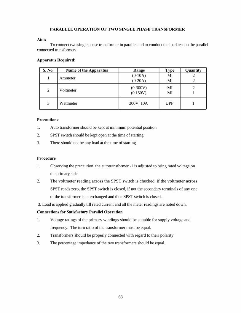
PARALLEL OPERATION OF TWO SINGLE PHASE TRANSFORMER
Aim:
To connect two single phase transformer in parallel and to conduct the load test on the parallel
connected transformers
Apparatus Required:
S. No. Name of the Apparatus
1 Ammeter
2 Voltmeter
Range Type Quantity
(0-10A) MI 2
(0-20A) MI 2
(0-300V) MI 2
(0.150V) MI 1
3 Wattmeter 300V, 10A UPF 1
Precautions:
1. Auto transformer should be kept at minimum potential position
2. SPST switch should be kept open at the time of starting
3. There should not be any load at the time of starting
Procedure
1. Observing the precaution, the autotransformer -1 is adjusted to bring rated voltage on
the primary side.
2. The voltmeter reading across the SPST switch is checked, if the voltmeter across
SPST reads zero, the SPST switch is closed, if not the secondary terminals of any one
of the transformer is interchanged and then SPST switch is closed.
3. Load is applied gradually till rated current and all the meter readings are noted down.
Connections for Satisfactory Parallel Operation
1. Voltage ratings of the primary windings should be suitable for supply voltage and
frequency. The turn ratio of the transformer must be equal.
2. Transformers should be properly connected with regard to their polarity
3. The percentage impedance of the two transformers should be equal.
68

Tabular Column
Vp Ip Wp (Watts) Is1 Is Is Vs Output η % Volts Amps OBS ACT Amps Amps Amps Volts Watts
Model Graph:
Result:
Two single phase transformers were connected in parallel and the load test was
conducted on the parallel connected transformers.
69

Post Lab Questions:
1. Does the transformer draw any current when its secondary in open?
2. Why?
70

THREE PHASE TRANSFORMER CONNECTION
Pre Lab Questions:
1. What are the possible three phase connections?
2. Mention the instrument transformers
71

THREE PHAE TRANSFORMER CONNECTIONS
Aim:
To connect the primary and secondary of the given 3 phase transformer in the
following different configurations and to conduct the load test on the same.
1. Star-Star connection
2. Delta - Delta connection
3. Delta - Star connection
4. Star-Delta connection
5. Scott connection
Apparatus Required:
S. No. Name of the Apparatus Range Type Quantity
1 Ammeter (0-5A) MI 2
2 Voltmeter
3 Wattmeter
(0-600V) MI 1
(0-600V) MI 1
600V, 5A UPF 1
300V, 5A UPF 1
Precaution:
1. The 3 phase variac should be kept in minimum potential position
2. There should not be any load at the time of starting
Procedure
1. The 3 phase transformer is connected in any one of the configurations as
mentioned above.
2. The 3 phase variac is varied gradually and rated voltage is applied to the
transformer.
3. Then load is applied gradually till rated current and the corresponding meter
readings are noted down.
4. The above procedure is repeated for all the configurations.
Formulae Used
1. Input = Wp watts
2. Output power = Ws Watts
3. % Efficiency = Wp / Ws x 100 %
72

THREE PHASE TRANSFORMER CONNECTIONS
THREE PHASE TRANSFORMER CONNECTIONS
73

THREE PHASE TRANSFORMER CONNECTIONS
THREE PHASE TRANSFORMER CONNECTIONS
74

Model Graph:
Tabular Column
Sl. Vp Ip Vs Is Wp Ws % η No. (Volts) (Amps) (Volts) (amps) (Watts) (Watts)
OBS ACT OBS ACT
Result:
The three phase transformer was connected in different configurations and the load test was
conducted on the same.
75

Pre Lab Questions:
1. What is biggest advantage of T -T connection over V - V connection for 3 phase
power transformer?
2. Which connection is best suited for 3 phase 4 wire service?
76