Table of Contents - Elektromotor-online · this manual thoroughly before using the inverter. ......
53
-
Upload
phungthuan -
Category
Documents
-
view
216 -
download
0
Transcript of Table of Contents - Elektromotor-online · this manual thoroughly before using the inverter. ......


1
Table of Contents
Chapter 0 Preface .............................................................................................................2 0.1 Preface .............................................................................................................................2
Chapter 1 Safety precautions.....................................................................................3
1.1 Before power up ..............................................................................................................3 1.2 During power up..............................................................................................................4 1.3 Before operation ............................................................................................................4 1.4 During operation ............................................................................................................4 1.5 Inverter Disposal ...........................................................................................................5
Chapter 2 Ambient Environment and Installation ...........................................6
2.1 Precautions for peripheral applications .......................................................................6 2.2 Specifications..................................................................................................................7
2.2.1 Product Specifications ...........................................................................................7 2.2.2 General Specifications ...........................................................................................9
2.3 Standard wiring.............................................................................................................11 2.3.1 Single Phase..........................................................................................................11 2.3.2 Single/Three Phase...............................................................................................12 2.3.3 Three Phase...........................................................................................................13
2.4 Terminal Description ....................................................................................................14 2.4.1 Description of main circuit terminals..................................................................14 2.4.2 Control circuit terminal description ....................................................................15
2.5 Outline Dimensions ....................................................................................................16
Chapter 3 Software Index ...........................................................................................25 3.1 Keypad Description.......................................................................................................25
3.1.1 Panel Function ......................................................................................................25 3.2 Programmable Functions Groups ...............................................................................26 Chapter 4 Troubleshooting and Maintenance .................................................47 4.1 Error display and corrective action .............................................................................47
4.1.1 Manual Reset and Auto-Reset .............................................................................47 4.1.2 Keypad Operation Error Instruction....................................................................49 4.1.3 Special conditions ................................................................................................50
4.2 General troubleshooting...............................................................................................51

2
Chapter 0 Preface 0.1 Preface
To extend the performance of the product and ensure personnel safety, please read this manual thoroughly before using the inverter. Should there be any problem in using the product that cannot be solved with the information provided in the manual, contact Our’s technical or sales representative who will be willing to help you. ※Precautions
The inverter is an electrical product. For your safety, there are symbols such as “Danger”, “Caution” in this manual as a reminder to pay attention to safety instructions on handling, installing, operating, and checking the inverter. Be sure to follow the instructions for highest safety.
Danger Indicates a potential hazard that could cause death or serious personal injury if misused.
Caution Indicates that the inverter or the mechanical system might be damaged if misused.
Danger Risk of electric shock. The DC link capacitors remain charged for five
minutes after power has been removed. It is not permissible to open the equipment until 5 minutes after the power has been removed.
Do not make any connections when the inverter is powered on. Do not check parts and signals on circuit boards during the inverter operation.
Do not disassemble the inverter or modify any internal wires, circuits, or parts.
Ensure that the Inveter Ground terminal is connected correctly.
Caution Do not perform a voltage test on parts inside the inverter. High voltage can
destroy the semiconductor components.
Do not connect T1(L), T2, and T3(N) terminals of the inverter to any AC input power supply.
CMOS ICs on the inverter’s main board are susceptible to static electricity. Do not touch the main circuit board.

3
1.1 Before Power Up
Danger
Make sure the main circuit connections are correct Single phase L1(L),L3(N), Three phase L1(L),L2,L3(N) are power-input terminals and must not be mistaken for T1,T2 and T3. Otherwise, inverter damage can result.
Caution The line voltage applied must comply with the inverter’s specified input
voltage.(See the nameplate) To avoid the front cover from disengaging, or other damge do not carry the
inverter by its covers. Support the drive by the heat sink when transporting. Improper handling can damage the inverter or injure personnel and should be avoided.
To avoid the risk of fire, do not install the inverter on a flammable object.Install on nonflammable objects such as metal.
This product provides the 24V for internal use only, do not use as the power supply sources for other external components, such as sensors, electronic components ... etc., otherwise it will cause adverse situation.
When disconnecting the remote keypad, turn the power off first to avoid any damage to the keypad or the inverter.
Caution This product is sold subject to EN 61800-3 and EN 61800-5-1.
In a domestic environment this product may cause radio interference in which case the user may be required to apply corrective measures.
Caution
Work on the device/system by unqualified personnel or failure to comply with warnings can result in severe personal injury or serious damage to material. Only suitably qualified personnel trained in the setup, installation, commissioning and operation of the product should carry out work on the device/system.
Only permanently-wired input power connections are allowed.

4
1.2 During Power Up
Danger When the momentary power loss is longer than 2 seconds, the inverter will not
have sufficient stored power for its control circuit. Therefore, when the power is re-applied, the run operation of the inverter will be based on the setup of following parameters:
• Run parameters. 00-02 or 00-03. • Direct run on power up. Parameter. 07-04 and the status of external run
switch,
Note-: the start operation will be regardless of the settings for parameters 07-00/07-01/07-02.
Danger. Direct run on power up. If direct run on power up is enabled and inverter is set to external run with the run FWD/REV switch closed then the inverter will restart.
Danger Prior to use, ensure that all risks and safety implications are considered.
When the momentary power loss ride through is selected and the power loss is short, the inverter will have sufficient stored power for its control circuits to function, therefore,when the power is resumed the inverter will automatically restart depending on the setup of parameters 07-00 & &- 7-01.
1.3 Before Operation
Caution
Make sure the inverter model and rating are the same as that set in parameter 13-00.
Note :On power up the supply voltage set in parameter 01-01 will flash on the display for 2 seconds.
1.4 During Operation Danger
Do not connect or disconnect the motor during operation. Otherwise, It may cause the inverter to trip or damage the unit.

5
Caution
Do not touch heat radiating components such as heat sinks and brake
resistors.
The inverter can drive the motor from low speed to high speed. Verify the allowable speed ranges of the motor and the associated machinery.
Risk of electric shock. The DC link capacitors remain charged for five minutes after power has been removed. It is not permissible to open the equipment until 5 minutes after the power has been removed.
Caution
The Inverter should be used in environments with temperature range from (14-104°F) or (-10 to 50°C) and relative humidity of 95%.
Danger
Make sure that the power is switched off before disassembling or checking any components.
1.5 Inverter Disposal
Caution
Please dispose of this unit with care as an industrial waste and according to your required local regulations.
The capacitors of inverter main circuit and printed circuit board are considered as hazardous waste and must not be burnt.
The plastic enclosure and parts of the inverter such as the cover board will release harmful gases if burnt.
Danger To avoid electric shock, do not take the front cover off while power is on. The motor will restart automatically after stop when auto-restart function is
enabled. In this case, care must be taken while working around the drive and associated equipment .
The operation of the stop switch is different than that of the emergency stop switch. The stop switch has to be activated to be effective. Emergency stop has to be de-activated to become effective.

6
Chapter 2 Environment & Installation
2.1 Considerations for peripheral equipment (
Power
Ensure that the supply voltage is correct. A molded-case circuit breaker or fused disconnect must be installed between the AC source and the inverter
Circuit Breaker & RCD
Use a molded-case circuit breaker that conforms to the rated voltage and current of the inverter. Do not use the circuit breaker as the run/stop switch for the inverter. Residual Current Circuit Breaker(RCD) Current setting should be 200mA or above and the operating time at 0.1 second or longer to prevent malfunctions.
Magnetic contactor
Normally a magnetic contactor is not needed. A contactor can be used to perform functions such as external control and auto restart after power failure. Do not use the magnetic contactor as the run/stop switch of the inverter.
AC reactor for power quality improvement
When a 200V/400V inverter with rating below 15KW is connected to a high capacity power source (600KVA or above) then an AC reactor can be connected for power factor improvement and reducing harmonics.
Input noise filter
E510 inverter has a built-in filter to Class “A” first Environment. (CategoryC2) To satisfy the required EMC regulations for your specific application you may require an additional EMC filter.
Inverter
Connect the single phase power to Terminals, L1(L) & L3(N). Warning! Connecting the input terminals T1, T2, and T3 to AC input power will damage the inverter.Output terminals T1, T2, and T3 are connected to U, V, and W terminals of the motor. To reverse the motor rotation direction just swap any two wires at terminals T1, T2, and T3. Ground the Inverter and motor correctly. Ground Resistance for 200V power<100 Ohms. Ground Resistance for 400V power<10 Ohms
Motor
Three-phase induction motor. Voltage drop on motor due to long cable can be calculated. Volts drop should be < 10%. Phase-to-phase voltage drop (V) =
3 ×resistance of wire (Ω/km)×length of line(m)×current×10-3
Grounding

7
2.2 Specifications 2.2.1 Product Specifications 220V Class:Single phase Model:E510-- H1F 2P5 201 202 203 Horse power (HP) 0.5 1 2 3 Suitable motor capacity (KW) 0.4 0.75 1.5 2.2 Rated output current (A) 3.1 4.5 7.5 10.5 Rated capacity (KVA) 1.2 1.7 2.90 4.00 Input voltage range(V) Single Phase:200~240V,50/60HZ Allowable voltage fluctuation +10%-15% Output voltage range(V) Three phase: 0~240V Input current (A)* 8.5 12 16 23.9 Inverter net weight (KG) 1.65 1.65 2.5 2.5 Allowable momentary power loss time (S) 2.0 2.0 2.0 2.0 Enclosure IP20 220V Class:Single/Three phase Model:E510-- H 2P5 201 202 203 Horse power (HP) 0.5 1 2 3 Suitable motor capacity (KW) 0.4 0.75 1.5 2.2 Rated output current (A) 3.1 4.5 7.5 10.5 Rated capacity (KVA) 1.2 1.7 2.90 4.00 Input voltage range(V) Single/Three Phase:200~240V, 50/60HZ Allowable voltage fluctuation +10%-15% Output voltage range(V) Three phase: 0~240V Input current (A)* 8.5/4.5 12/6.5 16/11 23.9/12.5 Inverter net weight (KG) 1.6 1.6 2.5 2.5 Allowable momentary power loss time (S) 2.0 2.0 2.0 2.0
Enclosure IP20 220VClass:Three phase Model: E510-- H3 202 205 208 210 215 220 Horse power (HP) 2 5 7.5 10 15 20 Suitable motor capacity (KW) 1.5 3.7 5.5 7.5 11 15 Rated output current (A) 7.5 17.5 26 35 48 64 Rated capacity (KVA) 2.9 6.7 9.9 13.3 20.6 27.4 Input voltage range(V) Three phase :200~240V,50/60HZ Allowable voltage fluctuation +10%-15% Output voltage range(V) Three phase : 0~240V Input current (A)* 11 20.5 33 42 57 70 Inverter net weight (KG) 2.5 2.5 6.5 6.5 10.1 10.4 Allowable momentary power loss time (S) 2.0 2.0 2.0 2.0 2.0 2.0 Enclosure IP20 *The input current is calculated value at full rated output current.

8
400VClass:Three phase Model:E510-- H3 401 402 403 405 Horse power (HP) 1 2 3 5 Suitable motor capacity (KW) 0.75 1.5 2.2 3.7 Rated output current (A) 2.3 3.8 5.2 8.8 Rated capacity (KVA) 1.7 2.9 4.0 6.7 Input voltage range(V) Three phase:380~480V,50/60HZ Allowable voltage fluctuation +10%-15% Output voltage range(V) Three phase:0~ 480V Input current (A)* 4.2 5.6 7.3 11.6 Inverter net weight (KG) 1.7 1.7 2.5 2.5 Allowable momentary power loss time (S) 2.0 2.0 2.0 2.0 Enclosure IP20 Model:E510-- H3(F) 408 410 415 420 425 Horse power (HP) 7.5 10 15 20 25 Suitable motor capacity (KW) 5.5 7.5 11 15 18.5 Rated output current (A) 13.0 17.5 25 32 40 Rated capacity (KVA) 9.9 13.3 19.1 27.4 34 Input voltage range(V) Three phase:380~480V,50/60HZ Allowable voltage fluctuation +10%-15% Output voltage range(V) Three phase: 0~480V Input current (A)* 17 23 31 38 48 Inverter net weight (KG) 6.7 6.7 6.7 10.5 10.5 Allowable momentary power loss time (S) 2.0 2.0 2.0 2.0 2.0
Enclosure IP20 *The input current is calculated value at full rated output current.

9
2.2.2 General Specifications Item E510
Control Mode V/F Control, Vector Control Output Frequency 0.01~650.00Hz Starting Torque 150%/1Hz(Vector) Speed Control Range 1:50
Digital input: 0.01Hz Setting resolution Analog input:0.06Hz/60Hz
Keypad:Set directly with keys or the VR on the keypad External Input Terminlas: AI1(0/2~10V), AI2(0/4~20mA)input Multifunction input up/down function(Group3)
Setting
Setting frequency by communication method.
Frequency
Frequency limit Lower and upper frequency limits 3 skip frequency settings. Keypad run, stop button External terminals: Multi- operation-mode2 / 3 wire selection Jog operation
Run Operation set
Run signal by communication method. V / F curve setting 18 fixed curves and one customized curve Carrier frequency 1~16KHz Acceleration and deceleration control
2 off Acc / dec time parameters. 4 off S curve parameters.
Multifunction input 26 functions (refer to description on group3) Multifunction output 19 functions (refer to description on group3) Multifunction analog output 5 functions (refer to description on group3)
Main Control Features
Main features
Overload Detection,16 preset speeds,Auto-run,Acc/Dec Switch (2 Stages),Main/Alt run Command select,Main/Alt Frequency Command select,PID control, torque boost, V/F start Frequency, Fault reset, Firemode.
LED
Display :parameter / parameter value / frequency / line speed / DC voltage / output voltage / output current / PID feedback / input and output terminal status / Heat sink temperature / Program Version / Fault Log.
Display
LED Status Indicator Run / Stop / Forward / Reverse ,and etc.
Overload Protection The relays to protect the motor and the inverter. (150%/1min)
Over voltage ·220V: >410V ,380V: >820V Under Voltage ·220V: <190V , 380V: <380V Momentary Power Loss Restart Inverter auto-restart after a momentary power loss.
Stall Prevention Stall prevention for Acceleration/ Deceleration/ Operation.
Short-circuit output terminal Electronic Circuit Protection
Grounding Fault Electronic Circuit Protection
Protective Functions
Other protection features Protection for overheating of heat sink,The carrier
frequency decreasing with the temperature function,fault output,reverse prohibit,prohibit for

10
direct start after power up and error recovery ,parameter lock up
All frames include brake transistor
Communication control Standard built-in RS485 communication (Modbus), One to one or One to many control.
Operating temperature -10~50 (Note1) Storage temperature -20~60
Humidity 95% RH or less (no condensation) (Compliance with IEC 60068 - 2-78)
Shock 20Hz or less 1G(9.8m/s²)20~50Hz 0.6G(5.88m/s²) (Compliance with IEC 60068 - 2-6)
Environment
Protection class IP20 Note1: –10 ~ 50 in distributor (without dustproof cover/ paster),
–10 ~40 outside distributor (with dustproof cover/ paster).

11
2.3 Standard wiring 2.3.1 Single Phase:
Frequency indicator deviceor PID input
Frequency Indicator
(
MCCBL1(L)
L3(N)(
MC
ACPowersource
+
T1
10VAI1
AI2
AGND
0 ~10V
M
0~20mA
-
Inverter output
Induction Motor
S3
S4
S5
S6
S2
FWD (Run/Stop) S1
R2C
RS485
CON2
AO
AGND
+
- 0~10VDC
NPN
PNP
AI1 AI2
AV1AV2
JP1
Ground
REV (Run/Stop)
R2A
R1A
R1B
R1C
T2
T3
JP2
JP3
Molded-case circuit breaker
Molded-case circuit breaker
Magnetic contactor
Magnetic contactor
+ 24V(PNP)COM (NPN)
Safety Function InputSGSF
Speed Control
Mul
tifun
ctio
n In
put T
erm
inal
s
E
E EP
P
Reset
Indicates twisted-pair shield wire P
Shows control circuitShows main circuit
Indicates shield wire
*2
*1: Independent protection circuit is suggested to be installed for the purpose of protecting the circuit. *2: If the jumper wire between SF and SG is connected, the inverter stops output. *3: JP1:NPN/PNP selection, JP2:AI1 0~10V/0~20mA selection, JP3:AI2 0~10V/0~20mA selection*4: Connect to terminal Com or +24vdc depending on position of JP1.
*3
1:Data+2:Data-3:Data+4:Reserved5:Reserved6:Data-7:5V8:GND
*4
Model: 200V: E510-2P5-H1F/ E510-201-H1F/ E510-202-H1F/
E510-203-H1F

12
2.3.2 Single/Three Phase
Model: 200V: E510-2P5-H/ E510-201-H/ E510-202-H/ E510-203-H

13
2.3.3 Three phase
Frequency indicator deviceor PID input
Frequency Indicator
(
MCCBL1(L)
+
T1
L3(N)(
10VAI1
AI2
MC
AGND
0 ~10V
M
0~20mA
-
L2(
Inverter outputAC
Power source
Induction Motor
S3
S4
S5
S6
S2
FWD (Run/Stop) S1
R2C
RS485
CON2
AO
AGND
+
- 0~10VDC
NPN
PNP
AI1 AI2
AV1AV2
JP1
Ground
Three phases power input
REV (Run/Stop)
R2A
R1A
R1B
R1C
T2
T3
JP2
JP3
Safety Function InputSGSF
Speed Control
Mul
tifun
ctio
n In
put T
erm
inal
s
E
E EP
P
Reset
* *3
1:Data+2:Data-3:Data+4:Reserved5:Reserved6:Data-7:5V8:GND
+ 24V(PNP)COM (NPN)
*4
Indicates twisted-pair shield wire P
Shows control circuitShows main circuit
Indicates shield wire
*1: Independent protection circuit is suggested to be installed for the purpose of protecting the circuit. *2: If the jumper wire between SF and SG is connected, the inverter stops output. *3: JP1:NPN/PNP selection, JP2:AI1 0~10V/0~20mA selection, JP3:AI2 0~10V/0~20mA selection*4: Connect to terminal Com or +24vdc depending on position of JP1.
Model: 200V:E510-205-H3/E510-208-H3/E510-210-H3/
E510-215-H3/E510-220-H3 400V:E510-401-H3(F)/ E510-402-H3(F)/ E510-403-H3(F)/
E510-405-H3(F)/E510-408-H3(F)/E510-410-H3(F)/ E510-415-H3(F)/E510-420-H3(F)/E510-425-H3(F)

14
2.4 Terminal Description 2.4.1 Description of main circuit terminals Terminal symbols TM1 Function Description
L1(L) L2
L3(N) Main power input, L1(L)/L2/L3(N)
T1 T2 T3
Inverter output, connect to U/V/W terminals of motor
P BR
Braking resistor connection terminal: Used in applications when it is required to stop a high inertia load rapidly. (refer to specifications of the braking resistor)
Ground terminal

15
2.4.2 Control circuit terminal description Type Terminal Terminal function Signal level
S1 ForwardStop (Preset), Multi function input terminal S2 ReverseStop (Preset), Multi function input terminal S3 Preset Speed0(5-02),Multi function input terminal S4 Preset Speed1(5-03), Multi function input terminal S5 Preset Speed2(5-05), Multi function input terminal
Digital input signal
S6 Fault reset input, Multi function input terminal
24 VDC, 8 mA, Optical coupling isolation(Max,voltage30 Vdc, Input impedance 3.3kΩ)
R1A NO(Normally open)
R1B NC(Normally closed)
R1C COMMON R2A
Relay output
R2C
Multi function output:Run,Fault,setting Frequency ,Frequency Reached,Auto Restart,Momentary AC Power Loss,Rapid Stop ,Base Block Stop Mode,Motor Overload Protection,Drive Overload Protection,Over-torque Threshold Level、Preset Current level Reached、Preset Brake Frequency Reached,PID Feedback Signal Loss,Final count value reached, Initial count value recahed,PLC Status Indicator ,PLC control…
250VAC/1A(30VDC/1A)
24V Digital signal common terminal (JP1 Switching NPN position) 24VPower
supply COM Digital signal common terminal (JP1 Switching PNP position)
±15%,Max output current 60mA
10V Built in Power for an external speed potentiometer 10V(Max current:2mA)
AI1
Multifunctional analog input available JP2 switching voltage or current input Voltage:JP2 Switching AVI position Current:JP2 Switching ACI position
0 ~ 10V,(Max current:2mA) (Input impedance: 153KΩ)
AI2
Multifunctional analog input available JP3 switching voltage or current input Voltage:JP3 cut to AVI position Current:JP3 cut to ACI position
0 ~ 10V,0 ~20mA (Input impedance: 153KΩ)
AGND The analog common terminal ----
The analog input signal
Shielding wire connecting terminal (The earth) ----
AO Multifunctional analog output terminal*3 0 ~10V,(Max current:2mA) The analog onput signal
AGND The analog common terminal ----
SF Safety switch SG
Terminal SF is for safety switch, SF can cut off the inverter voltage output.
Control circuit terminal:

16
2.5 Outline Dimensions mm(inch) Frame1 Single/Three phase: 200V 0.5~1HP; Single phase: 200V 0.5~1HP; Three phase: 200V 2HP; 400V 1~2HP;
2- Q1
2- Q2
W1
H1 H
W2W
E
D
D1
Unit:mm(inch)
Dimensions Model
W W1 W2 H H1 D D1 E d1 d2
N.W (KG) Tolerance table
E510-2P5-H E510-201-H
E510-2P5-H1F E510-201-H1F E510-202-H3* E510-401-H3 E510-402-H3
E510-401-H3F E510-402-H3F
90.6 (3.57)
81 (3.19)
81 (3.19)
163.6 (6.44)
153 (6.02)
146.8 (5.78)
141 (5.55)
48 (1.89)
4.3 (0.17)
2.2 (0.09) 1.7
0 ~ 10 ± 0.1 10 ~ 50 ± 0.2
50 ~ 100 ± 0.3 100 ~ 200± 0.5 200 ~ 400 ± 0.8
* 2012 Q1 available
2-d2
2-d1

17
Frame2 Single/Three phase: 200V 2~3HP; Single phase: 200V 2~3HP; Three phase: 200V 5HP; 400V 3~5HP;
W1H1 H2
W2
W
2-Q1
E
D1
DD2
2-Q2
H
Unit:mm(inch)
Dimensions Model W W1 W2 H H1 H2 D D1 D2 E d1 d2
N.W (KG) Tolerance table
E510-202-H
E510-203-H
E510-202-H1F
E510-203-H1F
E510-205-H3
E510-403-H3
E510-405-H3
E510-403-H3F
E510-405-H3F
128.7 (5.07)
118 (4.65)
118 (4.65)
187.6 (7.39)
177.6 (6.99)
197.5 (7.78)
147.8 (5.82)
133.8 (5.27)
141.8 (5.58)
48.2 (1.9)
4.5
(0.18)
2.25 (0.08) 2.5
0 ~ 10 ± 0.1 10 ~ 50± 0.2
50 ~ 100± 0.3 100 ~ 200± 0.5 200 ~ 400± 0.8
2-d1
2-d2

18
Frame3 Three phase: 200V 8~10HP; 400V 8~15HP;
W1
H
W
DD1D2
EW2
H22-Q1
H1
2-Q2
Unit:mm(inch)
Dimensions
Model W W1 W2 H H1 H2 D D1 D2 E d1 d2
N.W (KG)
Tolerance table
E510-208-H3
E510-210-H3
E510-408-H3
E510-410-H3
E510-415-H3
E510-408-H3F
E510-410-H3F
E510-415-H3F
186.9 (7.36)
176 (6.92)
175 (6.89)
260.9 (10.27)
249.8 (9.83)
273 (10.75)
195 (7.68)
184 (7.24)
189 (7.44)
84.7 (3.33)
4.5 (0.18)
2.3 (0.09) 6.7
0 ~ 10± 0.1 10 ~ 50± 0.2
50 ~ 100± 0.3
100 ~ 200± 0.5
200 ~ 400± 0.8
2-d1
2-d2
19
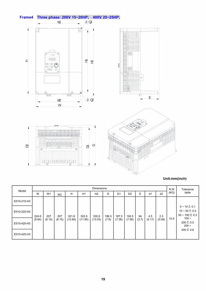
Frame4 Three phase: 200V 15~20HP; 400V 20~25HP;
D1 DD2
E
2- Q1
2- Q2
H1 H2
W2W
HW1
Unit:mm(inch)
Dimensions
Model W W1 W2 H H1 H2 D D1 D2 E d1 d2
N.W (KG)
Tolerance table
E510-215-H3
E510-220-H3
E510-420-H3
E510-425-H3
224.6 (8.84)
207 (8.15)
207 (8.15)
321.6 (12.66)
303.5 (11.95)
330.9 (13.03)
198.3 (7.8)
187.5 (7.38)
192.5 (7.58)
94 (3.7)
4.5 (0.17)
2.3 (0.09) 10.5
0 ~ 10± 0.1 10 ~ 50± 0.2
50 ~ 100± 0.3100 ~
200± 0.5 200 ~
400± 0.8

20
Frame4 (Built-in EMC filter) Three: 400V 20~25HP;
D1 DD2
E
2-Q
H
W
W1H2
E2
H1
E1
Unit:mm(inch)
Dimensions
Model W W1 H H1 H2 D D1 D2 E E1 E2 d1
N.W (KG) Tolerance table
E510-420-H3F
E510-425-H3F
207 (8.15)
224.6 (8.84)
400.8 (15.78)
320.8 (12.63)
405.8 (15.98)
198.3 (7.81)
187.5 (7.38)
192.5 (7.58)
86 (3.39)
94 (3.7)
192.5 (7.58)
6 (0.24) 10.5
0 ~ 10± 0.1 10 ~ 50± 0.2
50 ~ 100± 0.3100 ~
200± 0.5 200 ~
400± 0.8
2-d1

21
Frame1(NEMA1) Single/Three phase: 200V 0.5~1HP; Single phase: 200V 0.5~1HP; Three phase: 200V 2HP; 400V 1~2HP;
W1
W
HH1
D
D1D2
E
E1
2- Q
Unit:mm(inch) Dimensions
Model W W1 H H1 D D1 D2 E E1 d1
N.W (KG) Tolerance table
E510-2P5-H
E510-201-H
E510-2P5-H1F
E510-201-H1F
E510-401-H3
E510-402-H3
E510-401-H3F
E510-402-H3F
90.65
(3.57)
80.5
(3.17)
186.2
(7.33)
189.2
(7.45)
146.8
(5.77)
137.8
(5.42)
140.8
(5.54)
41.2
(1.62)
120.5
(4.74)
4.33
(0.17) 1.9
0 ~ 10± 0.1 10 ~ 50± 0.2
50 ~ 100± 0.3 100 ~ 200± 0.5200 ~ 400± 0.8
2-d1

22
Frame2(NEMA1) Single/Three phase: 200V 2~3HP; Single phase: 200V 2~3HP; Three phase: 200V 5HP; 400V 3~5HP;
W1
W
HH1
E1
E
D
D1D22-Q
Unit:mm(inch)
Dimensions
Model W W1 H H1 D D1 D2 E E1 d1
N.W (KG) Tolerance table
E510-202-H
E510-203-H
E510-202-H1F
E510-203-H1F
E510-205-H3
E510-403-H3
E510-405-H3
E510-403-H3F
E510-405-H3F
128.7
(5.06)
118.3
(4.66)
210.6
(8.29)
213.6
(8.41)
147.8
(5.82)
133.8
(5.27)
141.8
(5.58)
46.1
(1.81)
121.1
(4.77)
4.5
(0.18) 2.8
0 ~ 10± 0.1 10 ~ 50± 0.2
50 ~ 100± 0.3100 ~ 200± 0.5200 ~ 400± 0.8
2-d1

23
Frame3(NEMA1) Three phase: 200V 8~10HP; 400V 8~15HP; W1
H
W
DD1D2
E
H1
2-Q
E1
Unit:mm(inch) Dimensions
Model W W1 H H1 D D1 D2 E E1 d1
N.W (KG) Tolerance table
E510-208-H3
E510-210-H3
E510-408-H3
E510-410-H3
E510-415-H3
E510-408-H3F
E510-410-H3F
E510-415-H3F
186.9
(7.36)
175
(6.89)
291
(11.47)
296
(11.65)
195
(7.67)
184
(7.24)
189
(7.44)
76.7
(3.02)
170.6
(6.72)
4.5
(0.17) 7.1
0 ~ 10± 0.1 10 ~ 50± 0.2
50 ~ 100± 0.3100 ~ 200± 0.5200 ~ 400± 0.8
2-d1

24
Frame4(NEMA1) Three phase: 200V 15~20HP; 400V 20~25HP;
D1 DD2
2- Q
H
W
H1
W1
E
E1
Unit:mm(inch)
Dimensions Model
W W1 H H1 D D1 D2 E E1 d1 N.W (KG) Tolerance table
E510-215-H3
E510-220-H3
E510-420-H3
E510-425-H3
E510-420-H3F
E510-425-H3F
224.6
(8.84)
207
(8.15)
350.1
(13.78)
355.1
(13.98)
198.3
(7.81)
187.5
(7.38)
192.5
(7.58)
86
(3.89)
174
(6.85)
6
(0.24) 11
0 ~ 10± 0.1 10 ~ 50± 0.2
50 ~ 100± 0.3100 ~ 200± 0.5200 ~ 400± 0.8
2-d1

25
Chapter 3 Software Index 3.1 Keypad Description 3.1.1 Operator Panel Functions
Type Item Function
Main digital displays Frequency Display, Parameter, voltage, Current, Temperature , Fault messages.
Digital display &
LEDs LED Status
Hz/RPM: ON when the frequency or line speed is displayed. OFF when the parameters are displayed.
FWD: ON while the inverter is running forward. Flashes while stopped.
REV: ON while the inverter is running reverse. Flashes while stopped.
FUN: ON when the parameters are displayed. OFF when the frequency is displayed.
Variable Resistor FREQ SET Used to set the frequency
RUN RUN: Run at the set frequency. STOP STOP: Decelerate or Coast to Stop. Increment parameter number and preset values. Decrement parameter number and preset values.
FWD/REV (Dual function
keys)
FWD: Forward Run REV: Reverse Run
DSP/FUN (Dual function
keys)
DSP: Switch between available displays FUN: Used to examine the parameter content
READ/ENTER (Dual function
keys)
READ: ENTER: Used to display the preset value of parameters and for saving the changed parameter values.
Keys On Keypad (8 buttons)
</ RESET (Dual function keys)
“<”Left Shift: used while changing the parameters or parameter values RESET: Use to Reset alarms or resettable faults

26
3.2 Programmable Parameter Groups Parameter Group No.
Description
Group 00 Basic parameters
Group 01 V/F Pattern selections & setup
Group 02 Motor parameters
Group 03 Multi function digital Inputs/Outputs
Group 04 Analog signal inputs/ Analog output
Group 05 Preset Frequency Selections.
Group 06 Auto Run(Auto Sequencer) function
Group 07 Start/Stop command setup
Group 08 Drive and motor Protection
Group 09 Communication function setup
Group 10 PID function setup
Group 11 Performance control functions
Group 12 Digital Display & Monitor functions
Group 13 Inspection & Maintenance function
Group 14 PLC Setting function
Group 15 PLC Monitoring function
Parameter notes for Parameter Groups
*1 Parameter can be adjusted during running mode
*2 Cannot be modified in communication mode
*3 Does not change with factory reset
*4 Read only

27
Group 00- The basic parameters group No. Description Range Factory
Setting Unit Note
0:V/F mode 00-00 Control Mode Selection 1:Vector mode
0 -
00-01 Reserved 0:Keypad 1:External Run/Stop Control 2:Communication 00-02 Main Run Command
Source Selection 3:PLC
0 -
0:Keypad 1:External Run/Stop Control 00-03 Alternative Run Command
Source Selection 2:Communication 0 -
0: Forward/Stop-Reverse/Stop 1: Run/Stop- Reverse/Forward 00-04 Operation Modes for
External Terminals 2: 3-Wire Control Mode-Run/Stop
0 -
0: UP/DOWM of Keypad 1:Potentiometer on Keypad 2:External AI1Analog Signal Input 3:External AI2 Analog Signal Input 4:External Up/Down Frequency Control 5:Communication Setting Frequency
00-05 Main Frequency Command Source Selection
6:PID Ouput Frequency
0 -
0:UP/DOWM of Keypad 1:Potentiometer on Keypad 2:External AI1Analog Signal Input 3:External AI2 Analog Signal Input 4:External Up/Down Frequency Control 5:Communication Setting Frequency
00-06 Alternative Frequency Command Source Selection
6:PID Ouput Frequency
4 -
00-07 Main and Alternative Frequency Command modes
0: Main Or Alternative Frequency 1: Main frequency+ Alternative Frequency
0 -
00-08 Communication Frequency Command
0.00~650.00 60.00 Hz *4
0:Save the frequency before power down 00-09 Frequency command
save mode 1:Save Keypad Frequency
0 -
0:by Current Frequency Command 1:by 0 Frequency Command 00-10 Initial Frequency
Selection (keypad mode) 2:by 00-11
0 -
00-11 Initial Frequency Keypad Mode 0.00~650.00 50.00/60.00 Hz
00-12 Frequency Upper Limit 0.01~650.00 50.00/60.00 Hz 00-13 Frequency Lower Limit 0.00~649.99 0.00 Hz 00-14 Acceleration Time 1 0.1~3600.0 10.0 Sec *1 00-15 Deceleration Time 1 0.1~3600.0 10.0 Sec *1 00-16 Acceleration Time 2 0.1~3600.0 10.0 Sec *1 00-17 Deceleration Time 2 0.1~3600.0 10.0 Sec *1 00-18 Jog Frequency 1.00~25.00 2.00 Hz *1 00-19 Jog Acceleration Time 0.1~25.5 0.5 Sec *1 00-20 Jog Deceleration Time 0.1~25.5 0.5 Sec *1
28
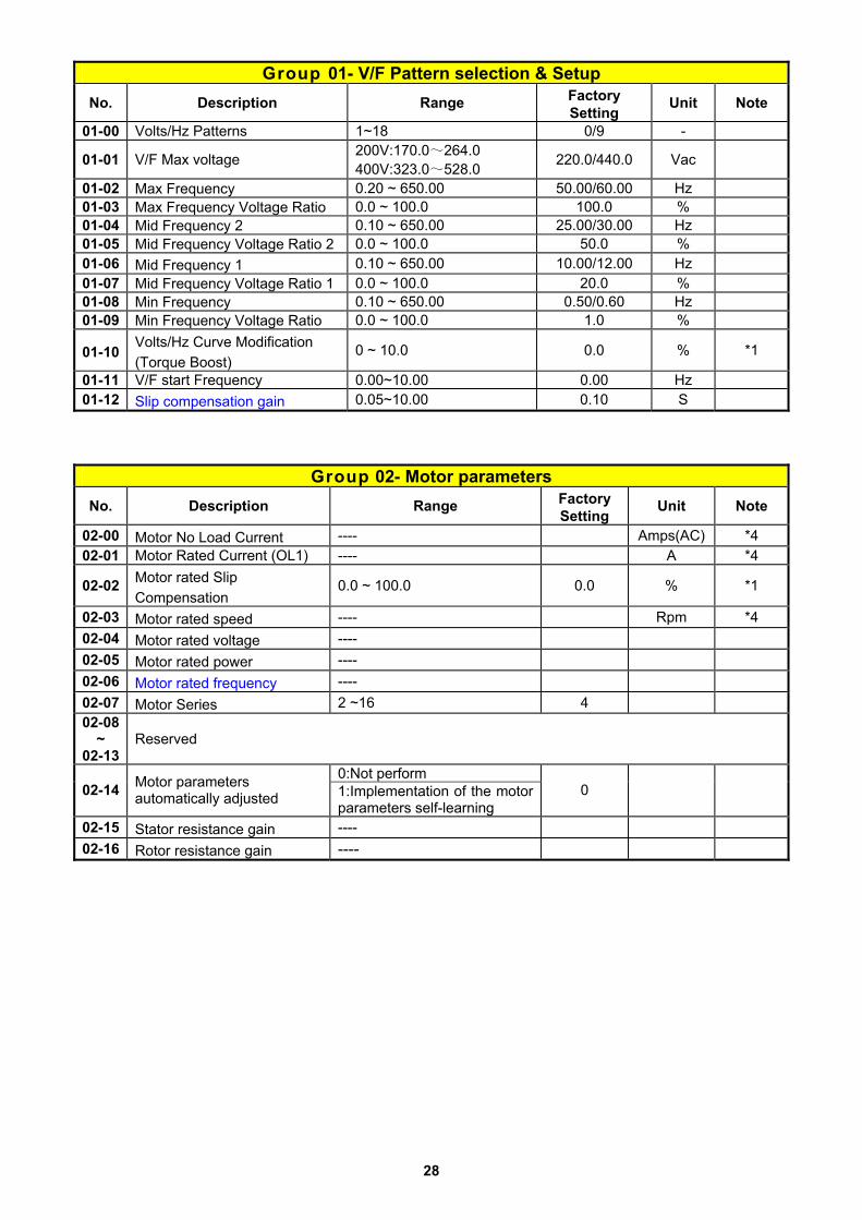
Group 01- V/F Pattern selection & Setup No. Description Range Factory
Setting Unit Note
01-00 Volts/Hz Patterns 1~18 0/9 -
01-01 V/F Max voltage 200V:170.0~264.0 400V:323.0~528.0 220.0/440.0 Vac
01-02 Max Frequency 0.20 ~ 650.00 50.00/60.00 Hz 01-03 Max Frequency Voltage Ratio 0.0 ~ 100.0 100.0 % 01-04 Mid Frequency 2 0.10 ~ 650.00 25.00/30.00 Hz 01-05 Mid Frequency Voltage Ratio 2 0.0 ~ 100.0 50.0 % 01-06 Mid Frequency 1 0.10 ~ 650.00 10.00/12.00 Hz 01-07 Mid Frequency Voltage Ratio 1 0.0 ~ 100.0 20.0 % 01-08 Min Frequency 0.10 ~ 650.00 0.50/0.60 Hz 01-09 Min Frequency Voltage Ratio 0.0 ~ 100.0 1.0 %
01-10 Volts/Hz Curve Modification (Torque Boost)
0 ~ 10.0 0.0 % *1
01-11 V/F start Frequency 0.00~10.00 0.00 Hz 01-12 Slip compensation gain 0.05~10.00 0.10 S
Group 02- Motor parameters No. Description Range Factory
Setting Unit Note
02-00 Motor No Load Current ---- Amps(AC) *4 02-01 Motor Rated Current (OL1) ---- A *4
02-02 Motor rated Slip Compensation
0.0 ~ 100.0 0.0 % *1
02-03 Motor rated speed ---- Rpm *4 02-04 Motor rated voltage ---- 02-05 Motor rated power ---- 02-06 Motor rated frequency ---- 02-07 Motor Series 2 ~16 4 02-08
~ 02-13
Reserved
0:Not perform 02-14 Motor parameters
automatically adjusted 1:Implementation of the motor parameters self-learning
0
02-15 Stator resistance gain ---- 02-16 Rotor resistance gain ----

29
Group 00- Basic parameters
No. Description Range Factory Setting
Unit Note
0:V/F Mode 00-00 Control Mode Selection 1:Vector Mode
0 -
00-01 Reserved 0:Keypad 1:External Run/Stop Control 2:Communication 00-02 Main Run Command
Source Selection 3:PLC
0 -
0:Keypad 1:External Run/Stop Control 00-03 Alternative Run Command
Source Selection 2:Communication 0 -
0: Forward/Stop-Reverse/Stop 1: Run/Stop- Reverse/Forward 00-04 Operation Modes for
External Terminals 2: 3 Wire Control Mode-Run/Stop
0 -
0:UP/DOWM of Keypad 1:Potentiometer on Keypad 2:External AI1Analog Signal Input 3:External AI2 Analog Signal Input 4:External Up/Down Frequency Control5:Communication Setting Frequency
00-05 Main Frequency Command Source Selection
6:PID Ouput Frequency
0 -
0:UP/DOWM of Keypad 1:Potentiometer on Keypad 2:External AI1Analog Signal Input 3:External AI2 Analog Signal Input 4:External Up/Down Frequency Control5:Communication Setting Frequency
00-06 Alternative Frequency Command Source Selection
6:PID Ouput Frequency
4 -
00-07 Main and Alternative Frequency Command Modes
0: Main or Alternative Frequency 1: Main Frequency+ Alternative Frequency
0 -
00-08 Communication Frequency Command
0.00~650.00 60.00 Hz *4
0: Disable 00-09 Frequency Command Save on Power Down 1: Enable
0 -
0:by Current Frequency Command 1:by 0 Frequency Command 00-10
Initial Frequency Selection (keypad mode) 2:by 00-11
0 -
00-11 Initial Frequency Setpoint 0.00~650.00 50.00/60.00 Hz 00-12 Frequency Upper Limit 0.01~650.00 50.00/60.00 Hz 00-13 Frequency Lower Limit 0.00~649.99 0.00 Hz 00-14 Acceleration Time 1 0.1~3600.0 10.0 s *1 00-15 Deceleration Time 1 0.1~3600.0 10.0 s *1 00-16 Acceleration Time 2 0.1~3600.0 10.0 s *1 00-17 Deceleration Time 2 0.1~3600.0 10.0 s *1 00-18 Jog Frequency 1.00~25.00 2.00 Hz *1 00-19 Jog Acceleration Time 0.1~25.5 0.5 s *1 00-20 Jog Deceleration Time 0.1~25.5 0.5 s *1

30
Group 01- V/F Pattern selection & Setup
No. Description Range Factory Setting
Unit Note
01-00 Volts/Hz Patterns 1~18 0/9 -
01-01 V/F Max voltage 200V:170.0~264.0 400V:323.0~528.0 220.0/440.0 Vac
01-02 Max Frequency 0.20 ~ 650.00 50.00/60.00 Hz 01-03 Max Frequency Voltage Ratio 0.0 ~ 100.0 100.0 % 01-04 Mid Frequency 2 0.10 ~ 650.00 25.00/30.00 Hz 01-05 Mid Frequency Voltage Ratio 2 0.0 ~ 100.0 50.0 % 01-06 Mid Frequency 1 0.10 ~ 650.00 10.00/12.00 Hz 01-07 Mid Frequency Voltage Ratio 1 0.0 ~ 100.0 20.0 % 01-08 Min Frequency 0.10 ~ 650.00 0.50/0.60 Hz 01-09 Min Frequency Voltage Ratio 0.0 ~ 100.0 1.0 %
01-10 Volts/Hz Curve Modification (Torque Boost)
0 ~ 10.0 0.0 % *1
01-11 V/F start Frequency 0.00~10.00 0.00 Hz 01-12 Slip compensation gain 0.05~10.00 0.10 ms
Group 02- Motor parameters
No. Description Range Factory Setting
Unit Note
02-00 Motor No Load Current ---- Amps(AC) *4 02-01 Motor Rated Current (OL1) ---- A *4 02-02 Motor rated Slip Compensation 0.0 ~ 100.0 0.0 % *1 02-03 Motor rated speed ---- Rpm *4 02-04 Motor rated voltage ---- 02-05 Motor rated power ---- 02-06 Motor rated frequency ---- 02-07 Motor pole number 2 ~16 4 02-08 ~ 02-13
Reserved
0: Disable 02-14 Auto Tune 1: Start Auto tune function. 0
02-15 Stator resistance gain ---- 02-16 Rotor resistance gain ----

31
Group 03- External Digital Inputs and Relay Output Functions
No. Description Range Factory Setting
Unit Note
03-00 Multifunction Input Term. S1 0:Forward/Stop Command 0 - 03-01 Multifunction Input Term. S2 1:Reverse/Stop Command 1 - 03-02 Multifunction Input Term. S3 2:Preset Speed 0(5-02) 2 - 03-03 Multifunction Input Term. S4 3:Preset Speed 1(5-03) 3 - 03-04 Multifunction Input Term. S5 4:Preset Speed 2(5-05) 4 -
5:Preset Speed 3(5-09) 6:Jog Forward Command 7:Jog Reverse Command 8:Up Command 9:Down Command 10:Acc/Dec 2 11:Acc/Dec Disabled 12:Main/Alternative run source select 13:Main/ Alternative Frequency Command select 14: Rapid Stop ( Decel to stop ) 15: Base Block 16: Disabl PID Function 17:Reset 18:Auto Run Mode Enable 19:Speed Search 20:Energy Saving (only V/F) 21: Reset PID integral value to Zero 22:Pulse Input 23: Pulse input Counter Reset 24: PLC Input 25:Reserved 26:Reserved 27:Enable KEB Function
17 03-05 Multifunction Input Term. S6
28: Fire mode function (Valid for software issued after rev. 1.1 )
03-06 Up/Down frequency step 0.00~5.00 0.00 Hz 0: When Up/Down is used, the preset frequency is held as the inverter stops, and the UP/Down function is disabled 1:When Up/Down is used, the preset frequency is reset to 0 Hz as the inverter stops.
03-07 Up/Down Keep Frequency Status after Stop Command
2:When Up/Down is used, the preset frequency is held as the inverter stops, and the UP/Down is available.
0
-
03-08 S1~S6 scan confirmation 1~200 Number of Scan cycles 10 2ms xxxx0:S1 NO xxxx1:S1 NC xxx0x:S2 NO xxx1x:S2 NC xx0xx:S3 NO xx1xx:S3 NC x0xxx:S4 NO x1xxx:S4 NC
03-09 S1~ S5 switch type select
0xxxx:S5 NO 1xxxx:S5 NC
00000 -
- 03-10 S6 switch type select xxxx0:S6 NO xxxx1:S6 NC 00000

32
Group 03- External Digital Inputs and Relay Output Functions
No. Description Range Factory Setting
Unit Note
03-11 Output Relay RY1 ( Terminals R1A,R1B, R1C ) 0:Run 0 -
1:Fault 2:Setting Frequency Reached 3:Frequency Reached. Set by (3-13±3-14) 4:Output Frequency Detection1(> 3-13) 5:Output Frequency Detection2(< 3-13) 6:Auto Restart 7:Momentary AC Power Loss 8:Rapid Stop 9:Base Block 10:Motor Overload Protection(OL1) 11:Drive Overload Protection(OL2) 12: Over-torque Threshold Level (OL3) 13:Preset Output Current Reached 14:Brake Control ON 15:PID Feedback Signal Loss 16:Final count value reached (3-22~23) 17:Initial count value reached (3-22~23) 18:PLC Status Indicator (00-02)
03-12 Output Relay RY2. ( Terminals R2A, R2C )
19:PLC control
1
03-13 Frequency Reached Level 0.00~650.00 0.00 Hz *1
03-14 Frequency Reached Detection Range (±)
0.00~30.00 2.00 Hz *1
03-15 Preset output current reached 0.1~15.0 0.1 A
03-16 Preset output Current detection delay Time 0.1~10.0 0.1 s
03-17 Brake Release level 0.00~20.00 0.00 Hz
03-18 Brake Engage Level 0.00~20.00 0.00 Hz
03-19 Relay Output function type 0:A (Normally open) 1:B (Normally close) 0 -
03-20 Internal / external multi-function input terminal selection 0~63 0 -
03-21 Action to set the internal multi-function input terminals 0~63 0 -
03-22 Final preset Count reached 0~9999 0 - 03-23 Initial preset count reached 0~9999 0 -
0:Disable 03-24 Low Current detection selection. 1:Enable
0 -
03-25 Low Current Detection Level 5%~100% 20% %
03-26 Low Current Detection Delay Time 0.0~50.0s 20.0 s
※ “NO” indicates normally open, “NC” indicates normally closed.

33
Group 04- Analog signal inputs / Analog output
No. Description Range Factory Setting
Unit Note
AI1 AI2
0: 0~10V or(0~20mA)
0~10V or(0~20mA)
1: 0~10V or(0~20mA)
2~10V or(4~20mA)
2: 2~10V or(4~20mA)
0~10V or(0~20mA)
04-00
Analog Input Signal Type Select (AI1/AI2)
3: 2~10V or(4~20mA)
2~10V or(4~20mA)
0
-
04-01 AI1 Signal Verification Scan Rate 1~200 50 2ms
04-02 AI1 Gain 0 ~ 1000 100 % *1 04-03 AI1 Bias 0 ~ 100 0 % *1 04-04 AI1 Bias Selection 0: Positive 1: Negative 0 - *1 04-05 AI1 Slope 0: Positive 1: Negative 0 - *1
04-06 AI2 Signal Verification Scan Rate 1~200 50 2ms
04-07 AI2 Gain 0 ~ 1000 100 % *1 04-08 AI2 Bias 0 ~ 100 0 % *1 04-09 AI2 Bias Selection 0: Positive 1: Negative 0 - *1 04-10 AI2 Slope 0: Positive 1: Negative 0 - *1
04-11 Analog Output (AO) Mode
0: Output Frequency 1: Frequency Command 2: Output Voltage 3: DC Bus Voltage 4: Motor Current
0 - *1
04-12 Analog Output (AO) Gain 0 ~ 1000 100 % *1 04-13 Analog Output (AO) Bias 0 ~ 100 0 % *1 04-14 AO Bias Selection 0: Positive 1: Negative 0 - *1 04-15 AO Slope 0: Positive 1: Negative 0 - *1 04-16 F-Gain Function 0: Invalid 1: Effective 0 - *1

34
Group 05- Preset Frequency Selections
No. Description Range Factory Setting
Unit Note
0: Common Accel/Decel Accel/Decel 1 or 2 apply to all speeds
05-00 Preset Speed Control Mode Selection 1: Individual Accel/Decel for each preset speed
0-15 apply to the selected preset speeds (Acc0/Dec0~Acc15/Dec15)
0 -
05-01 Preset Speed 0 (Keypad Freq) 5.00 Hz
05-02 Preset Speed1 (Hz) 5.00 Hz *1 05-03 Preset Speed2 (Hz) 10.00 Hz *1 05-04 Preset Speed3 (Hz) 20.00 Hz *1 05-05 Preset Speed4 (Hz) 30.00 Hz *1 05-06 Preset Speed5 (Hz) 40.00 Hz *1 05-07 Preset Speed6 (Hz) 50.00 Hz *1 05-08 Preset Speed7 (Hz) 50.00 Hz *1 05-09 Preset Speed8 (Hz) 0.00 Hz *1 05-10 Preset Speed9 (Hz) 0.00 Hz *1 05-11 Preset Speed10 (Hz) 0.00 Hz *1 05-12 Preset Speed11 (Hz) 0.00 Hz *1 05-13 Preset Speed12 (Hz) 0.00 Hz *1 05-14 Preset Speed13 (Hz) 0.00 Hz *1 05-15 Preset Speed14 (Hz) 0.00 Hz *1 05-16 Preset Speed15 (Hz)
0.00 ~ 650.00
0.00 Hz *1 05-17 Preset Speed0-Acctime 10.0 s *1 05-18 Preset Speed0-Dectime 10.0 s *1 05-19 Preset Speed1-Acctime 10.0 s *1 05-20 Preset Speed1-Dectime 10.0 s *1 05-21 Preset Speed2-Acctime 10.0 s *1 05-22 Preset Speed2-Dectime 10.0 s *1 05-23 Preset Speed3-Acctime 10.0 s *1 05-24 Preset Speed3-Dectime 10.0 s *1 05-25 Preset Speed4-Acctime 10.0 s *1 05-26 Preset Speed4-Dectime 10.0 s *1 05-27 Preset Speed5-Acctime 10.0 s *1 05-28 Preset Speed5-Dectime 10.0 s *1 05-29 Preset Speed6-Acctime 10.0 s *1 05-30 Preset Speed6-Dectime 10.0 s *1 05-31 Preset Speed7-Acctime 10.0 s *1 05-32 Preset Speed7-Dectime 10.0 s *1 05-33 Preset Speed8-Acctime 10.0 s *1 05-34 Preset Speed8-Dectime 10.0 s *1 05-35 Preset Speed9-Acctime 10.0 s *1 05-36 Preset Speed9-Dectime 10.0 s *1
05-37 Preset Speed10-Acctime
10.0 s *1
05-38 Preset Speed10-Dectime
10.0 s *1
05-39 Preset Speed11-Acctime
0.1 ~ 3600.0
10.0 s *1

35
Group 05- Preset Frequency Selections
No. Description Range Factory Setting
Unit Note
05-40 Preset Speed11-Dectime
10.0 s *1
05-41 Preset Speed12-Acctime
10.0 s *1
05-42 Preset Speed12-Dectime
10.0 s *1
05-43 Preset Speed13-Acctime
10.0 s *1
05-44 Preset Speed13-Dectime
10.0 s *1
05-45 Preset Speed14-Acctime
10.0 s *1
05-46 Preset Speed14-Dectime
10.0 s *1
05-47 Preset Speed15-Acctime
10.0 s *1
05-48 Preset Speed15-Dectime
10.0 s *1
Group 06- Auto Run Function (Auto Sequencer)
No. Description Range Factory Setting
Unit Note
06-00 Auto Run Mode Selection (Sequencer)
0: Disabled. 1: Single cycle. (Continues to run from the Unfinished step if
restarted). 2: Periodic cycle.
(Continues to run from the unfinished step if restarted).
3: Single cycle, then holds the speed Of final step to run. (Continues to run from the
unfinished step if restarted). 4: Single cycle.
(Starts a new cycle if restarted). 5: Periodic cycle.
(Starts a new cycle if restarted). 6: Single cycle, then hold the speed of final step to run. (Starts a new cycle if restarted).
0 -
06-01 Auto _ Run Mode Frequency Command 1
0.00 Hz *1
06-02 Auto _ Run Mode Frequency Command 2
0.00 Hz *1
06-03 Auto _ Run Mode Frequency Command 3
0.00 Hz *1
06-04 Auto _ Run Mode Frequency Command 4
0.00 Hz *1
06-05 Auto _ Run Mode Frequency Command 5
0.00~650.00
0.00 Hz *1

36
Group 06- Auto Run Function (Auto Sequencer)
No. Description Range Factory Setting
Unit Note
06-06 Auto _ Run Mode Frequency Command 6
0.00 Hz *1
06-07 Auto _ Run Mode Frequency Command 7
0.00 Hz *1
06-08 Auto _ Run Mode Frequency Command 8
0.00 Hz *1
06-09 Auto _ Run Mode Frequency Command 9
0.00 Hz *1
06-10 Auto _ Run Mode Frequency Command10
0.00 Hz *1
06-11 Auto _ Run Mode Frequency Command 11
0.00 Hz *1
06-12 Auto _ Run Mode Frequency Command 12
0.00 Hz *1
06-13 Auto _ Run Mode Frequency Command 13
0.00 Hz *1
06-14 Auto _ Run Mode Frequency Command 14
0.00 Hz *1
06-15 Auto _ Run Mode Frequency Command 15
0.00 Hz *1
06-16 Auto_ Run Mode Running Time Setting 0
0.0 Sec
06-17 Auto_ Run Mode Running Time Setting 1
0.0 Sec
06-18 Auto_ Run Mode Running Time Setting 2
0.0 Sec
06-19 Auto_ Run Mode Running Time Setting 3
0.0 Sec
06-20 Auto_ Run Mode Running Time Setting 4
0.0 Sec
06-21 Auto_ Run Mode Running Time Setting 5
0.0 Sec
06-22 Auto_ Run Mode Running Time Setting 6
0.0 Sec
06-23 Auto_ Run Mode Running Time Setting 7
0.0 Sec
06-24 Auto_ Run Mode Running Time Setting 8
0.0 Sec
06-25 Auto_ Run Mode Running Time Setting 9
0.0 Sec
06-26 Auto_ Run Mode Running Time Setting 10
0.0 ~ 3600.0
0.0 Sec

37
Group 06- Auto Run Function (Auto Sequencer)
No. Description Range Factory Setting
Unit Note
06-27 Auto_ Run Mode Running Time Setting 11
0.0 Sec
06-28 Auto_ Run Mode Running Time Setting 12
0.0 Sec
06-29 Auto_ Run Mode Running Time Setting 13
0.0 Sec
06-30 Auto_ Run Mode Running Time Setting 14
0.0 Sec
06-31 Auto_ Run Mode Running Time Setting 15
0.0 Sec
06-32 Auto_ Run Mode Running Direction 0
0 -
06-33 Auto_ Run Mode Running Direction 1
0 -
06-34 Auto_ Run Mode Running Direction 2
0 -
06-35 Auto_ Run Mode Running Direction 3
0 -
06-36 Auto_ Run Mode Running Direction 4
0 -
06-37 Auto_ Run Mode Running Direction 5
0 -
06-38 Auto_ Run Mode Running Direction 6
0 -
06-39 Auto_ Run Mode Running Direction 7
0 -
06-40 Auto_ Run Mode Running Direction 8
0 -
06-41 Auto_ Run Mode Running Direction 9
0 -
06-42 Auto_ Run Mode Running Direction10
0 -
06-43 Auto_ Run Mode Running Direction 11
0 -
06-44 Auto_ Run Mode Running Direction12
0 -
06-45 Auto_ Run Mode Running Direction13
0 -
06-46 Auto_ Run Mode Running Direction 14
0 -
06-47 Auto_ Run Mode Running Direction 15
0: Stop 1: Forward 2: Reverse
0 -
※ Frequency of the step 0 is set by parameter 05-01, keypad frequency.

38
Group 07- Start/Stop Command Setup
No. Description Range Factory Setting
Unit Note
07-00 Momentary Power Loss and Restart
0: Momentary Power Loss and Restart Disable 1: Momentary Power Loss and Restart Enable
0 -
07-01 Auto Restart Delay Time 0.0~800.0 0.0 s
07-02 Number of Auto Restart Attempts 0~10 0 -
07-03 Reset Mode Setting
0: Enable Reset Only when Run Command is Off
1: Enable Reset when Run Command is On or Off
0 -
07-04 Direct Running on Power Up
0: Enable Direct run on power up 1: Disable Direct run on power up
1 -
07-05 Delay-ON Timer 1.0~300.0 1.0 S
07-06 DC Injection Brake Start Frequency (Hz) In Stop Mode
0.10 ~ 10.00 1.5 Hz
07-07 DC Injection Brake Level (%) In Stop Mode 0.0 ~ 150.0 50.0 %
07-08 DC Injection Brake Time (Seconds) In Stop Mode
0.0 ~ 25.5 0.5 s
07-09 Stopping Method 0: Deceleration to stop 1: Coast to stop 0 -
07-10 Starting Methods 0: Normal Start 1: Speed Search 0 -
07-11 Starting method for auto restart after fault 0: Speed Search 1: Normal start 0 -
07-12 Power Loss Ride Through Time 0.0 ~ 2.0 0.5 s
07-13 Main Circuit Low Voltage Detection Level 150.0~210.0 300.0~420.0 190.0/3
80.0 Vac
07-14 Kinetic Energy Back-up Deceleration Time 0.0~25.0: KEB Deceleration Time 0.0 s

39
Group 08- Drive & Motor Protection Functions
No. Description Range Factory Setting
Unit Note
08-00 Trip Prevention Selection
xxxx0: Enable Trip Prevention During Acceleration
xxxx1: Disable Trip Prevention During Acceleration
xxx0x: Enable Trip Prevention During Deceleration
xxx1x: Disable Trip Prevention During Deceleration
xx0xx: Enable Trip Prevention in Run Mode
xx1xx: Disable Trip Prevention in Run Mode
x0xxx: Enable Over Voltage Prevention in Run Mode
x1xxx: Disable Over Voltage Prevention in Run Mode
00000 -
08-01 Trip Prevention Level During Acceleration (%)
50 ~ 200 200
08-02 Trip Prevention Level During Deceleration (%)
50 ~ 200 200
08-03 Trip Prevention Level in Run Mode (%)
50 ~ 200 200
%1
08-04 Over Voltage Prevention Level in Run Mode
350.0~390.0/700.0~780.0 380.0/760.0
VDC
08-05 Electronic Motor Overload Protection Operation Mode
0: Enable Electronic Motor Overload Protection 1: Disable Electronic Motor Overload Protection
0 -
08-06 Operation After Overload Protection is Activated
0: Coast-to-Stop After Overload Protection is Activated
1: Drive Will Not Trip when Overload Protection is Activated (OL1)
0 -
08-07 Over Heat Protection ( cooling fan control)
0: Auto (Depends on temp.) 1: Operate while in RUN Mode 2: Always Run 3: Disabled
1 -
0: AVR Function Enable 1: AVR Function Disable 2: AVR Function Disable for Stop 3: AVR Function Disable for Deceleration. 4: AVR Function Disabled for Stop and Deceleration.
08-08 AVR Function (Auto Voltage Regulation)
5: When VDC>360V,AVR Function is Disabled for Stop and Deceleration.
4 -
08-09 Input Phase Loss Protection
0:Disabled 1:Enabled 0 -
0:Disabled 08-10 Output Phase Losts Protection 1:Enabled
0 -
0:Overload protection (Standard Motor) 08-11 Motor Type Selection 1:Overload protection (Inverter Duty Motor) 0 -
0: Motor Overload Protection for General loads (OL=103 %) (150% for 1 Minutes) 08-12 Motor Overload
Protection Curve 1: Motor Over load Protection for HVAC ( Fan & Pump) (OL=113%) (123% for 1 Minutes).
0 -
1 Base on the percentage of inverter rated current.
40
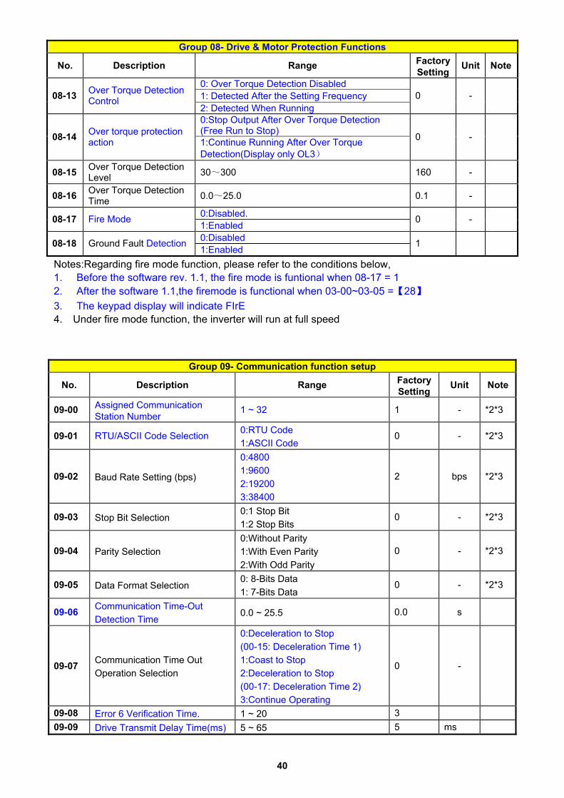
Group 08- Drive & Motor Protection Functions
No. Description Range Factory Setting
Unit Note
0: Over Torque Detection Disabled 1: Detected After the Setting Frequency 08-13 Over Torque Detection
Control 2: Detected When Running
0 -
0:Stop Output After Over Torque Detection (Free Run to Stop) 08-14 Over torque protection
action 1:Continue Running After Over Torque Detection(Display only OL3)
0 -
08-15 Over Torque Detection Level 30~300 160 -
08-16 Over Torque Detection Time 0.0~25.0 0.1 -
0:Disabled. 08-17 Fire Mode 1:Enabled
0 -
0:Disabled 08-18 Ground Fault Detection 1:Enabled
1
Notes:Regarding fire mode function, please refer to the conditions below, 1. Before the software rev. 1.1, the fire mode is funtional when 08-17 = 1 2. After the software 1.1,the firemode is functional when 03-00~03-05 =【28】 3. The keypad display will indicate FIrE 4. Under fire mode function, the inverter will run at full speed
Group 09- Communication function setup
No. Description Range Factory Setting
Unit Note
09-00 Assigned Communication Station Number
1 ~ 32 1 - *2*3
09-01 RTU/ASCII Code Selection 0:RTU Code 1:ASCII Code
0 - *2*3
09-02 Baud Rate Setting (bps)
0:4800 1:9600 2:19200 3:38400
2 bps *2*3
09-03 Stop Bit Selection 0:1 Stop Bit 1:2 Stop Bits
0 - *2*3
09-04 Parity Selection 0:Without Parity 1:With Even Parity 2:With Odd Parity
0 - *2*3
09-05 Data Format Selection 0: 8-Bits Data 1: 7-Bits Data
0 - *2*3
09-06 Communication Time-Out Detection Time
0.0 ~ 25.5 0.0 s
09-07 Communication Time Out Operation Selection
0:Deceleration to Stop (00-15: Deceleration Time 1) 1:Coast to Stop 2:Deceleration to Stop (00-17: Deceleration Time 2) 3:Continue Operating
0 -
09-08 Error 6 Verification Time. 1 ~ 20 3 09-09 Drive Transmit Delay Time(ms) 5 ~ 65 5 ms

41
Group 10- PID Function Setup
No. Description Range Factory Setting
Unit Note
10-00 PID Target Value Selection (When 00-03\00-04=6 This Function is Enabled)
0:Potentiometer on Keypad 1: Analog Signal Input. (AI1) 2: Analog Signal Input. (AI2) 3: Frequency Set by Communication 4: Keypad Frequency Parameter 10-02
1 - *1
10-01 PID Feedback Value Selection
0:Potentiometer on Keypad 1: Analog Signal Input. (AI1) 2: Analog Signal Input. (AI2) 3: Frequency Set by Communication
2 - *1
10-02 PID Target(Keypad Input) 0.0~100.0 50.0 % *1
10-03 PID Mode Selection
0:Disabled 1: Deviation D Control.
FWD Characteristic. 2: Feedback D Control
FWD Characteristic. 3: Deviation D Control
Reverse Characteristic. 4: Feedback D Control Reverse Characteristic.
0 -
10-04 Feedback Gain Coefficient 0.00 ~ 10.00 1.00 % *1 10-05 Proportional Gain 0.0 ~ 10.0 1.0 *1 10-06 Integral Time 0.0 ~ 100.0 10.0 s *1 10-07 Derivative Time 0.00 ~ 10.00 0.00 s *1
10-08 PID Offset 0: Positive 1: Negative
0 - *1
10-09 PID Offset Adjust 0 ~ 109 0 % *1 10-10 PID Output Lag Filter Time 0.0 ~ 2.5 0.0 s *1
10-11 Feedback Loss Detection Mode
0: Disabled 1: Enabled - Drive Continues to
Operate After Feedback Loss 2: Enabled - Drive "STOPS" After Feedback Loss
0 -
10-12 Feedback Loss Detection Level
0 ~ 100 0 %
10-13 Feedback Loss Detection Delay Time 0.0 ~25.5 1.0 s
10-14 Integration Limit Value 0 ~ 109 100 % *1
10-15 Integral Value Resets to Zero when Feedback Signal Equals the Target Value
0: Disabled 1: After 1 Second 30: After 30 Second (0~30)
0 -
10-16 Allowable Integral value Error Margin (Units, 1 Unit = 1/8192)
0 ~ 100 0 -
10-17 PID Sleep Frequency Level 0.00~650.00 0.00 Hz 10-18 PID Sleep Function Delay Time 0.0 ~25.5 0.0 s 10-19 PID Wake up frequency Level 0.00 ~ 650.00 0.00 Hz
10-20 PID Wake up function Delay Time 0.0 ~ 25.5 0.0 s
10-21 Max PID Feedback Setting Level 0 ~999 100 - *1 10-22 Min PID Feedback Setting Level 0 ~999 0 - *1

42
Group 11- Performance Control Functions
No. Description Range Factory Setting
unit Note
11-00 Reverse Operation Control 0: Reverse Command is Enabled 1: Reverse Command is Disabled
0 -
11-01 Carrier Frequency (kHz) 1~16 5 KHz
11-02 Carrier Mode Selection
0: Mode0, 3Phase PWM modulation 1: Mode1, 2Phase PWM modulation 2: Mode2, 2Phase Random PWM Modulation
0 -
11-03 Carrier Frequency Reduction by Temperature Rise
0:Disabled 1:Enabled
0 -
11-04 S-Curve Acc 1 0.0 ~ 4.0 0.00 s 11-05 S-Curve Acc 2 0.0 ~ 4.0 0.00 s 11-06 S-Curve Dec 3 0.0 ~ 4.0 0.00 s 11-07 S-Curve Dec 4 0.0 ~ 4.0 0.00 s 11-08 Skip Frequency 1 0.00 ~ 650.00 0.00 Hz *1 11-09 Skip Frequency 2 0.00 ~ 650.00 0.00 Hz *1 11-10 Skip Frequency 3 0.00 ~ 650.00 0.00 Hz *1
11-11 Skip Frequency Range Bandwith (±) 0.00 ~ 30.00 0.00 Hz *1
11-12 Energy Saving Gain (V/F Mode) 0 ~ 100 80 %
0:Invalid 1:Vaild 11-13 Regeneration Avoidance
Operation Selection 2:Vaild (Only in The Constant Speed)
0 -
11-14 Regeneration Avoidance Operation level 300~800V 380/760 V
11-15 Regeneration Avoidance Frequency Limit Compensation
0.00 ~ 15.00 3.00 Hz
11-16 Regeneration Avoidance Voltage Gain 0~200 100 %
11-17 Regeneration Avoidance Frequency Gain 0~200 100 %
Group 12 Digital Display & Monitor Functions
No. Description Range Factory Setting
Unit Note
00000~88888 Each digit can be set from 0 to 8 as listed below. 0: Default Display (Frequency and Parameters) 1:Output Current 2:Output Voltage 3:DC Voltage 4:Temperature 5:PID Feedback 6:Analog Signal Input.(AI1) 7:Analog Signal Input.(AI2)
12-00 Extended Display Mode
8: Pulse input Count value
00000 - *1
0:Integer (xxx) 1:One Decimal Place (xx.x) 12-01 PID Feedback Display
Format 2:Two Decimal Places (x.xx)
0 - *1

43
Group 12 Digital Display & Monitor Functions
No. Description Range Factory Setting
Unit Note
0:xxx-- 1:xxxpb(pressure) 12-02 PID Feedback Display Unit
Setting 2:xxxfl(flow)
0 - *1
12-03 Custom Units (Line Speed) Value 0~65535 1500/1800 RPM *1
0:Drive Output Frequency is Displayed 1: :Line Speed.Integer.(xxxxx) 2:Line Speed.One Decimal Place. (xxxx.x) 3:Line Speed.Two Decimal Places (xxx.xx)
12-04 Custom Units (Line Speed) Display Mode
4::Line Speed.Three Decimal Places (xx.xxx)
0 - *1
12-05 Inputs and Output Logic Status Display ( S1~S6, RY1 and RY2)
S1 S2 S3 S4 S5 S6
RY1 RY2
- - *4
xxxx0:Life Alarm of Inrush Current Suppression Circuit is Invalid xxxx1:Life Alarm of Inrush Current Suppression Circuit is Valid xxx0x:Life Alarm of Control Circuit Capacitors is Invalid xxx1x:Life Alarm of Control Circuit Capacitors is Valid
12-06
Alarm Selections for Inverter Components Life Expectancy
xx0xx:Life Alarm of Main Circuit Capacitors is Invalid xx1xx:Life Alarm of Main Circuit Capacitors is Valid
00000 - *1
12-07 Detect Main Circuit Capacitors Reserved
12-08 Display of Inrush Current Suppression Circuit 0~100 100 %
12-09 Display of Control Circuit Capacitors 0~100 100 %
12-10 Display of Main Circuit Capacitors 0~100 100 %
12-11 Output Current when Fault Appeared ---- 0 A
12-12 Output Voltage when Fault Appeared ---- 0 Vac
12-13 Output Frequency when Fault Appeared ---- 0 Hz
12-14 DC Bus Voltage when Fault Appeared ---- 0 Vac
12-15 Frequency Command when Fault Appeared ---- 0 Hz

44
Group 13 Inspection & Maintenance Functions
No. Description Range Factory Setting
unit Note
13-00 Drive Horsepower Code ---- - - *3 13-01 Software Version ---- - - *3*4
13-02 Fault Log (Latest 3 Faults) ---- - - *3*4
13-03 Accumulated Inverter Operation Time 1 0~23 - hour *3
13-04 Accumulated Inverter Operation Time 2 0~65535 ---- day *3
13-05 Accumulated Inverter Operation Time Mode
0: Power On time 1: Operation time
0 - *3
13-06 Parameter Lock
0:Enable all Functions 1: Preset Speeds from 05-01 to 05-15 Can’t be Changed 2:All Functions Can’t be Changed Except for Preset speeds from 05-01 to 05-15 3: Disable All Functions Except 13-06
0 -
13-07 Parameter Lock Code 00000~65535 00000 -
13-08 Reset Drive to Factory Settings
1150:Reset to Factory Setting(50Hz System) 1160:Reset to Factory Setting(60 Hz System) 1112:Reset PLC
00000 -

45
Group 14 PLC Setting function
No. Description Range Factory Setting
unit Note
14-00 Setting Value1 of T1 0~9999 0 - 14-01 Setting Value1 of T1 (mode 7) 0~9999 0 - 14-02 Setting Value1 of T2 0~9999 0 - 14-03 Setting Value1 of T2 (mode 7) 0~9999 0 - 14-04 Setting Value1 of T3 0~9999 0 - 14-05 Setting Value1 of T3 (mode 7) 0~9999 0 - 14-06 Setting Value1 of T4 0~9999 0 - 14-07 Setting Value1 of T4 (mode 7) 0~9999 0 - 14-08 Setting Value1 of T5 0~9999 0 - 14-09 Setting Value1 of T5 (mode 7) 0~9999 0 - 14-10 Setting Value1 of T6 0~9999 0 - 14-11 Setting Value1 of T6 (mode 7) 0~9999 0 - 14-12 Setting Value1 of T7 0~9999 0 - 14-13 Setting Value1 of T7 (mode 7) 0~9999 0 - 14-14 Setting Value1 of T8 0~9999 0 - 14-15 Setting Value1 of T8 (mode 7) 0~9999 0 - 14-16 Setting Value1 of C1 0~65535 0 - 14-17 Setting Value1 of C2 0~65535 0 - 14-18 Setting Value1 of C3 0~65535 0 - 14-19 Setting Value1 of C4 0~65535 0 - 14-20 Setting Value1 of C5 0~65535 0 - 14-21 Setting Value1 of C6 0~65535 0 - 14-22 Setting Value1 of C7 0~65535 0 - 14-23 Setting Value1 of C8 0~65535 0 - 14-24 Setting Value1 of AS1 0~65535 0 - 14-25 Setting Value2 of AS1 0~65535 0 - 14-26 Setting Value3 of AS1 0~65535 0 - 14-27 Setting Value1 of AS2 0~65535 0 - 14-28 Setting Value2 of AS2 0~65535 0 - 14-29 Setting Value3 of AS2 0~65535 0 - 14-30 Setting Value1 of AS3 0~65535 0 - 14-31 Setting Value2 of AS3 0~65535 0 - 14-32 Setting Value3 of AS3 0~65535 0 - 14-33 Setting Value1 of AS4 0~65535 0 - 14-34 Setting Value2 of AS4 0~65535 0 - 14-35 Setting Value3 of AS4 0~65535 0 - 14-36 Setting Value1 of MD1 0~65535 1 - 14-37 Setting Value2 of MD1 0~65535 1 - 14-38 Setting Value3 of MD1 1~65535 1 - 14-39 Setting Value1 of MD2 0~65535 1 - 14-40 Setting Value2 of MD2 0~65535 1 - 14-41 Setting Value3 of MD2 1~65535 1 - 14-42 Setting Value1 of MD3 0~65535 1 - 14-43 Setting Value2 of MD3 0~65535 1 - 14-44 Setting Value3 of MD3 1~65535 1 - 14-45 Setting Value1 of MD4 0~65535 1 - 14-46 Setting Value2 of MD4 0~65535 1 14-47 Setting Value3 of MD4 1~65535 1 -

46
Group 15 PLC Monitoring function
No. Description Range Factory Setting
unit Note
15-00 Current Value of T1 0~9999 0 - 15-01 Current Value of T1(mode 7) 0~9999 0 - 15-02 Current Value of T2 0~9999 0 - 15-03 Current Value of T2(mode 7) 0~9999 0 - 15-04 Current Value of T3 0~9999 0 - 15-05 Current Value of T3(mode 7) 0~9999 0 - 15-06 Current Value of T4 0~9999 0 - 15-07 Current Value of T4(mode 7) 0~9999 0 - 15-08 Current Value of T5 0~9999 0 - 15-09 Current Value of T5(mode 7) 0~9999 0 - 15-10 Current Value of T6 0~9999 0 - 15-11 Current Value of T6(mode 7) 0~9999 0 - 15-12 Current Value of T7 0~9999 0 - 15-13 Current Value of T7(mode 7) 0~9999 0 - 15-14 Current Value of T8 0~9999 0 - 15-15 Current Value of T8(mode 7) 0~9999 0 - 15-16 Current Value of C1 0~65535 0 - 15-17 Current Value of C2 0~65535 0 - 15-18 Current Value of C3 0~65535 0 - 15-19 Current Value of C4 0~65535 0 - 15-20 Current Value of C5 0~65535 0 - 15-21 Current Value of C6 0~65535 0 - 15-22 Current Value of C7 0~65535 0 - 15-23 Current Value of C8 0~65535 0 - 15-24 Current Value of AS1 0~65535 0 - 15-25 Current Value of AS2 0~65535 0 - 15-26 Current Value of AS3 0~65535 0 - 15-27 Current Value of AS4 0~65535 0 - 15-28 Current Value of MD1 0~65535 0 - 15-29 Current Value of MD2 0~65535 0 - 15-30 Current Value of MD3 0~65535 0 - 15-31 Current Value of MD4 0~65535 0 - 15-32 Current Value of TD 0~65535 0 μs

47
Chapter 4 Troubleshooting and Maintenance 4.1 Error display and corrective action 4.1.1 Manual Reset and Auto-Reset
Faults which can not be recovered manually Display content Cause Corrective action -OV-
Voltage too high when stopped Detection circuit malfunction Consult with the supplier
-LV-
Voltage too low when stopped
1. Power voltage too low 2. Pre-charge resistor or fuse
burnt out. 3. Detection circuit malfunction
1.Check if the power voltage is correct
2.Replace the pre-charge resistor or the fuse
3.Return the inverter -OH-
The inverter is overheated when stopped
1. Detection circuit malfunction2. Ambient temperature too
high or bad ventilation
Improve the ventilation conditions, if no result then replace the inverter
EPr
Current Sensor detection error
Current sensor error or circuit malfunction Consult with the supplier
COt
EEPROM problem Faulty EEPROM Consult with the supplier
CtEr
Current Sensor detection error
Current sensor error or circuit malfunction
Consult with the supplier
Faults which can be recovered manually and automatically Display content Cause Corrective action OC-A
Over-current at acceleration
1.Acceleration time too short 2.The capacity of the motor
exceeds the capacity of the inverter
3.Short circuit between the motor coil and the case
4.Short circuit between motor wiring and ground
5.IGBT module damaged
1.Set a longer acceleration time
2.Replace inverter with one that has the same rating as that of the motor
3.Check the motor 4.Check the wiring 5. Consult with the supplier
OC-C
Over-current at fixed speed
1. Transient load change 2. Transient power change
1. Increase the capacity of the inverter
2.Install inductor on the power Supply input side
OC-d
Over-current at deceleration
The preset deceleration time is too short.
Set a longer deceleration time
OC-S
Over current at start
1.Short circuit between the motor coil and the case
2.Short circuit between motor coil and ground
3.the IGBT module damaged
1.Inspect the motor 2.Inspect the wiring 3. Consult with the supplier
OV-C Excessive Voltage 1.Deceleration time setting 1.Set a longer deceleration

48
during operation/ deceleration
too short or excessive load inertia 2.Power voltage varies widely (fluctuates)
time 2. Add a brake resistor or brake module 3.Add a reactor at the power input side
Err4
CPU Illegal interrupt External noise If it often occurs, please
Consult with the supplier.
PF
Input phase Loss Abnormal fluctuations in the
main circuit voltage
1. Check the main circuit power supply wiring. 2. Check the power supply voltage
ud-C
Low current detection
Input current< Low current detection level
Set the level according to the actual situation
LF
Output phase loss Occurrence of lacking phase
at Inverter output side
1.Check Output cables wiring is disconnected or the connection error occurred 2.Determine resistance between the lines 3.Check whether the terminals are loose
Faults which can be recovered manually but not automatically Display content Cause Corrective action
OC
Over-current during stop
Detection circuit malfunction Consult with the supplier
OL1
Motor overload loading too large Consider increasing the
Motor capacity
OL2
Inverter overload Excessive Load Consider increasing the
inverter capacity
OL3
Over torque
1. Load too large 2.the setting of (8-15、8-16) too small
1. Increase the inverter capacity 2. Set(8-15、8-16) as needed
LV-C
Voltage too low during operation
1.Power voltage too low 2.Power voltage varies widely (fluctuates)
1.Improve power quality 2.Consider adding a reactor at the power input side
OVSP
Motor rotating too fast
Rotation speed and the set speed value vary widely
1.Load may be too large 2.Check if the set speed is correct.
LIFE1
The life of the inrush current
suppression circuit alarm
Inrush current suppression circuit is damaged Return the inverter for repair
LIFE2
The life of Capacitor Control Circuit alarm
Capacitor Control Circuit is damaged Return the inverter for repair
LIFE3
Main Circuit Capacitor life expectancy alarm
Capacitor Main Circuit is damaged Return the inverter for repair

49
GF
Output side ground Fault
While output is connected to ground , and grounding current flow through the circuit, output of inverter will be stopped. this protect function is set by 08-18
1) Check the motor winding resistance for failures.
2) Check the motor cable for ground short circuits
4.1.2Keypad Operation Error Instruction
Display content Cause Corrective action LOC
1. Parameter already locked 2.Motor direction locked 3. Parameter password(13 - 07) enabled
1. Attempt to modify frequency parameter while 13-06>0. 2.Attempt to reverse direction when 11- 00=1。 3. Parameter (13 - 07) enabled, set the correct password will show LOC.
1. Adjust 13-06 2.Adjust 11-00
Err1
Keypad operation error
1.Press or while 00-05/00-06>0 or running at preset speed. 2.Attempt to modify the Parameter.Can not be modified during operation (refer to the parameter list).
1.The or is available for modifying the parameter only when 00-05/00-06=0 2. Modify the parameter in STOP mode.
Err2
Parameter setting error
1. 00-13 is within the range of(11-08 ± 11-11) or (11-09 ± 11-11) or (11-10 ± 11-11) 2.00- 12≦00-13
1. Modify 11-08~11-10 or 11-11
2. Set 00-12>00-13
Err5
Modification of parameter is not available in communication
1.Control command sent during communication.
2.Attempt to modify the function 09-02 ~ 09-05 during communication
1.Issue enable command before communication
2. Set parameters 09-02 ~ 09-05 function before communication
Err6
Communication failed
1.Wiring error 2.Communication parameter setting error. 3.Incorrect communication protocol
1. Check hardware and wiring2. Check Functions
(09-00~09- 05).
Err7
Parameter conflict
1.Attempt to modify the function 13-00/13-08.
2.Voltage and current detection circuit is abnormal.
If reset is not possible, please consult with the supplier.

50
4.1.3 Special conditions Display Fault Description
StP0
Zero speed at stop Occurs when preset frequency <0.1Hz
StP1
Fail to start directly On power up.
If the inverter is set for external terminal control mode (00-02/00-03=1) and direct start is disabled (07-04=1) The inverter cannot be started and will flash STP1. The run input is active at power-up, refer to descriptions of (07-04).
StP2
Keypad Stop Operated when inverter in external Control mode.
If the Stop key is pressed while the inverter is set to external control mode (00-02/00-03=1) then‘STP2’flashes after stop. Release and re-activate the run contact to restart the inverter.
E.S.
External Rapid stop
When external rapid stop input is activated the inverter will decelerate to stop and the display will flash with E.S. message.
b.b.
External base block
When external base block input is activated the inverter stops immediately and then the display will flash with b.b. message.
PdEr
PID feedback loss PID feedback loss is detected.
AtEr
Auto tuninig error 1.Motor nameplate data Input errors.
2. Emergency stop is activated while auto tuning.
FIrE
Fire Mode
1. Software rev below 1.1, the fire mode functions when 08-17 = 1
2. Software ver 1.1 and above,the firemode functions when 03-00~03-05 =【28】
3. The diplay on the keypad indicates FIrE 4. Under fire mode function, the inverter will run at full speed

51
4.2 General troubleshooting Status Checking point Remedy
Is the wiring for the output terminals correct?
Wiring must match U, V, and W terminals of the motor. Motor runs
in wrong direction Is the wiring for forward and
reverse signals correct? Check for correct wiring.
Is the wiring for the analog frequency inputs correct? Check for correct wiring.
Is the setting of operation mode correct? Check the operation mode of the operator.
The motor speed can not be regulated.
Is the load too excessive? Reduce the load. Check the motor specifications (poles, voltage…) correct? Confirm the motor specifications.
Is the gear ratio correct? Confirm the gear ratio.
Motor running speed too high or too low
Is the setting of the highest output frequency correct? Confirm the highest output frequency
Is the load too excessive? Reduce the load.
Does the load vary excessively?1.Minimize the variation of the load. 2. Consider increasing the capacities of the
inverter and the motor. 1. Consider adding an AC reactor at the power
input side if using single-phase power.
Motor speed varies unusually
Is the input power erratic or is there a phase loss ? 2. Check wiring if using three-phase power. Is the power connected to the correct L1(L), L2, and L3(N) terminals? is the charging indicator lit ?
1. Is the power applied ? 2. Turn the power OFF and then ON again. 3. Make sure the power voltage is correct. 4. Make sure screws are secured firmly.
Is there voltage across the output terminals T1, T2, and T3? Turn the power OFF and then ON again.
Is overload causing the motor to stall? Reduce the load so the motor will run.
Are there any abnormalities in the inverter? Is there a forward or reverse run command ?
See error descriptions to check wiring and correct if necessary.
Has the analog frequency signal been input?
1.Is analog frequency input signal wiring correct?
2.Is voltage of frequency input correct?
Motor can not run
Is the operation mode setting correct? Operate through the digital keypad