Table of Contents - Mississippisp.mdot.ms.gov/Roadway Design/CADD/Microstation/CADD...
24
Table of Contents ROADWAY DESIGN IPLOT AND MICROSTATION PRINTING PROCEDURES Introduction IPLOT (Projectwise Interplot) IPLOT DIALOG INTERFACE (Plotting within Microstation) IPLOT ORGANIZER (Plotting outside Microstation – Batch Plot) Rescaling Plot Sets in Microstation Video IPLOT Instructor-led Training Video for New Users IPLOT PLOTTING PROCEDURES Creating IPLOT PDF plots Creating a PDF with IPLOT inside Microstation Creating a PDF Plot Set with IPLOT Organizer Video for creating PDF files with IPLOT Standard PDF File Names IPLOT Settings Files IPLOT Resources and Non-Standard IPLOT Plotting IPLOT Software Custom Configuration Files Roadway Design Plotter Hardware Guide MICROSTATION PRINTING (MPLOT) PROCEDURES Introduction Roadway Design Plot Drivers (PLTCFG) Print Style Library Microstation Printing PDF Creation Plotting Procedure Microstation V8i Print Organizer Video Instructor-led Recording of an Online Microstation Print Organizer Class
Transcript of Table of Contents - Mississippisp.mdot.ms.gov/Roadway Design/CADD/Microstation/CADD...
Table of Contents
ROADWAY DESIGN IPLOT AND MICROSTATION PRINTING PROCEDURES
Introduction
IPLOT (Projectwise Interplot)
IPLOT DIALOG INTERFACE (Plotting within Microstation)
IPLOT ORGANIZER (Plotting outside Microstation – Batch Plot)
Rescaling Plot Sets in Microstation Video
IPLOT Instructor-led Training Video for New Users
IPLOT PLOTTING PROCEDURES
Creating IPLOT PDF plots
Creating a PDF with IPLOT inside Microstation
Creating a PDF Plot Set with IPLOT Organizer
Video for creating PDF files with IPLOT
Standard PDF File Names
IPLOT Settings Files
IPLOT Resources and Non-Standard IPLOT Plotting
IPLOT Software Custom Configuration Files
Roadway Design Plotter Hardware Guide
MICROSTATION PRINTING (MPLOT) PROCEDURES
Introduction
Roadway Design Plot Drivers (PLTCFG)
Print Style Library
Microstation Printing PDF Creation Plotting Procedure
Microstation V8i Print Organizer Video
Instructor-led Recording of an Online Microstation Print Organizer Class
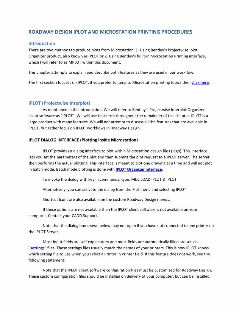
ROADWAY DESIGN IPLOT AND MICROSTATION PRINTING PROCEDURES
Introduction There are two methods to produce plots from Microstation. 1. Using Bentley’s Projectwise Iplot Organizer product, also known as IPLOT or 2. Using Bentley’s built-in Microstation Printing interface, which I will refer to as MPLOT within this document.
This chapter attempts to explain and describe both features as they are used in our workflow.
The first section focuses on IPLOT, if you prefer to jump to Microstation printing topics then click here.
IPLOT (Projectwise Interplot) As mentioned in the introduction, We will refer to Bentley’s Projectwise Interplot Organizer
client software as “IPLOT”. We will use that term throughout the remainder of this chapter. IPLOT is a large product with many features. We will not attempt to discuss all the features that are available in IPLOT, but rather focus on IPLOT workflows in Roadway Design.
IPLOT DIALOG INTERFACE (Plotting inside Microstation)
IPLOT provides a dialog interface to plot within Microstation design files (.dgn). This interface lets you set the parameters of the plot and then submits the plot request to a IPLOT server. The server then performs the actual plotting. This interface is meant to plot one drawing at a time and will not plot in batch mode. Batch mode plotting is done with IPLOT Organizer interface.
To invoke the dialog with key in commands, type: MDL LOAD IPLOT & IPLOT
Alternatively, you can activate the dialog from the FILE menu and selecting IPLOT
Shortcut Icons are also available on the custom Roadway Design menus.
If these options are not available then the IPLOT client software is not available on your computer. Contact your CADD Support.
Note that the dialog box shown below may not open if you have not connected to any printer on the IPLOT Server.
Most input fields are self-explanatory and most fields are automatically filled are set via “settings” files. These settings files usually match the names of your printers. This is how IPLOT knows which setting file to use when you select a Printer in Printer field. If this feature does not work, see the following statement:
Note that the IPLOT client software configuration files must be customized for Roadway Design. These custom configuration files should be installed on delivery of your computer, but can be installed
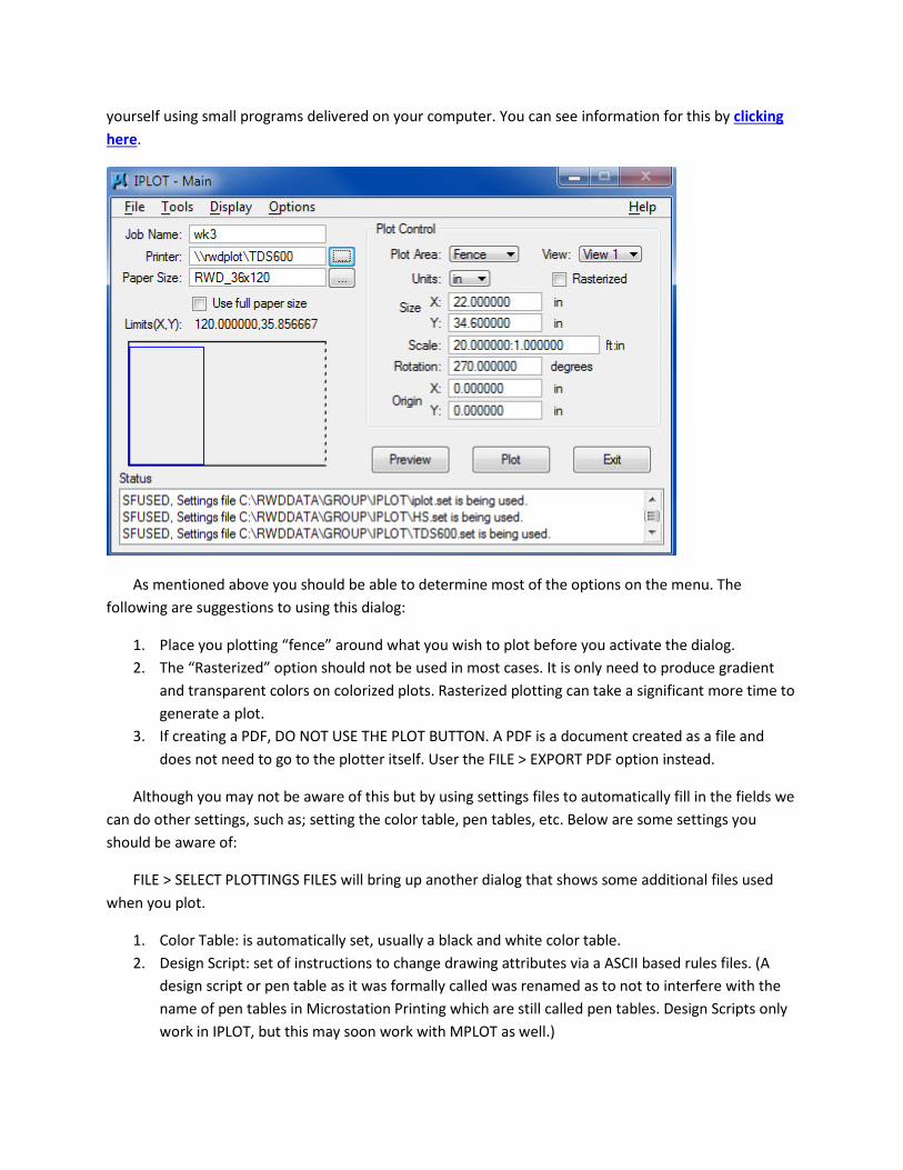
yourself using small programs delivered on your computer. You can see information for this by clicking here.
As mentioned above you should be able to determine most of the options on the menu. The following are suggestions to using this dialog:
1. Place you plotting “fence” around what you wish to plot before you activate the dialog. 2. The “Rasterized” option should not be used in most cases. It is only need to produce gradient
and transparent colors on colorized plots. Rasterized plotting can take a significant more time to generate a plot.
3. If creating a PDF, DO NOT USE THE PLOT BUTTON. A PDF is a document created as a file and does not need to go to the plotter itself. User the FILE > EXPORT PDF option instead.
Although you may not be aware of this but by using settings files to automatically fill in the fields we can do other settings, such as; setting the color table, pen tables, etc. Below are some settings you should be aware of:
FILE > SELECT PLOTTINGS FILES will bring up another dialog that shows some additional files used when you plot.
1. Color Table: is automatically set, usually a black and white color table. 2. Design Script: set of instructions to change drawing attributes via a ASCII based rules files. (A
design script or pen table as it was formally called was renamed as to not to interfere with the name of pen tables in Microstation Printing which are still called pen tables. Design Scripts only work in IPLOT, but this may soon work with MPLOT as well.)
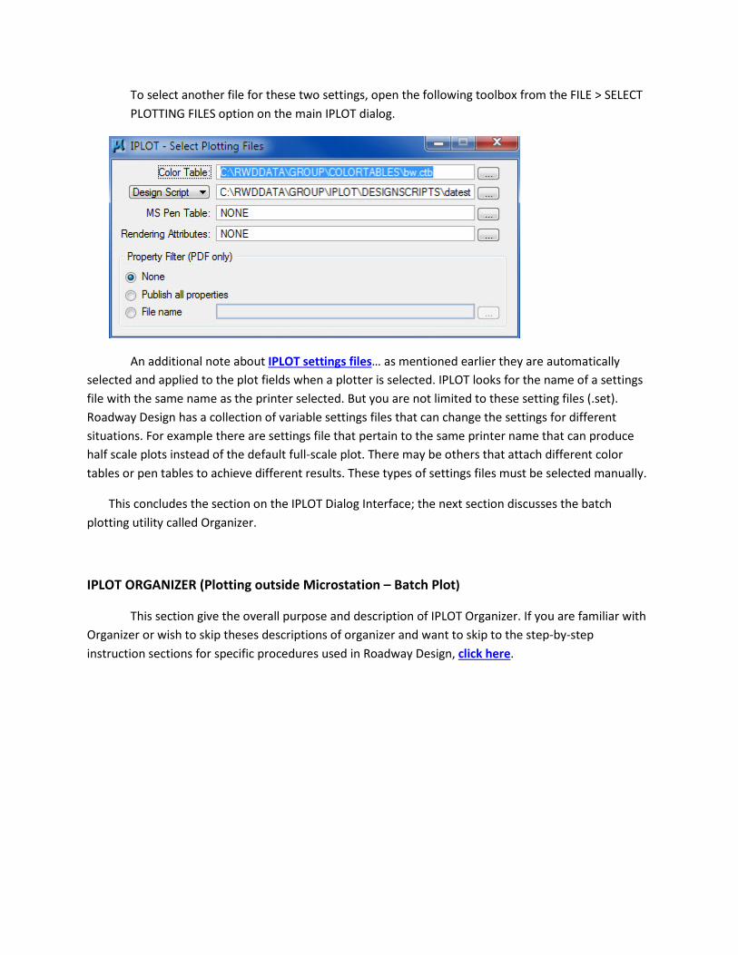
To select another file for these two settings, open the following toolbox from the FILE > SELECT PLOTTING FILES option on the main IPLOT dialog.
An additional note about IPLOT settings files… as mentioned earlier they are automatically selected and applied to the plot fields when a plotter is selected. IPLOT looks for the name of a settings file with the same name as the printer selected. But you are not limited to these setting files (.set). Roadway Design has a collection of variable settings files that can change the settings for different situations. For example there are settings file that pertain to the same printer name that can produce half scale plots instead of the default full-scale plot. There may be others that attach different color tables or pen tables to achieve different results. These types of settings files must be selected manually.
This concludes the section on the IPLOT Dialog Interface; the next section discusses the batch plotting utility called Organizer.
IPLOT ORGANIZER (Plotting outside Microstation – Batch Plot)
This section give the overall purpose and description of IPLOT Organizer. If you are familiar with Organizer or wish to skip theses descriptions of organizer and want to skip to the step-by-step instruction sections for specific procedures used in Roadway Design, click here.
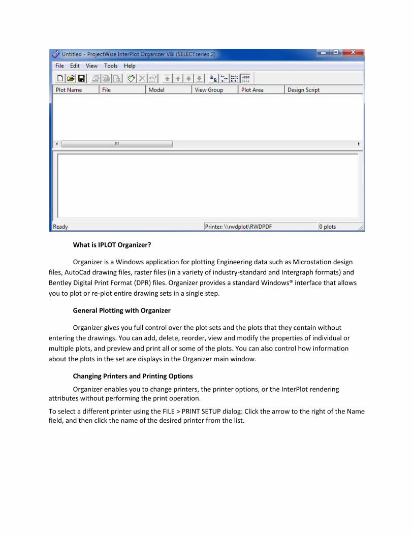
What is IPLOT Organizer?
Organizer is a Windows application for plotting Engineering data such as Microstation design files, AutoCad drawing files, raster files (in a variety of industry-standard and Intergraph formats) and Bentley Digital Print Format (DPR) files. Organizer provides a standard Windows® interface that allows you to plot or re-plot entire drawing sets in a single step.
General Plotting with Organizer
Organizer gives you full control over the plot sets and the plots that they contain without entering the drawings. You can add, delete, reorder, view and modify the properties of individual or multiple plots, and preview and print all or some of the plots. You can also control how information about the plots in the set are displays in the Organizer main window.
Changing Printers and Printing Options
Organizer enables you to change printers, the printer options, or the InterPlot rendering attributes without performing the print operation.
To select a different printer using the FILE > PRINT SETUP dialog: Click the arrow to the right of the Name field, and then click the name of the desired printer from the list.
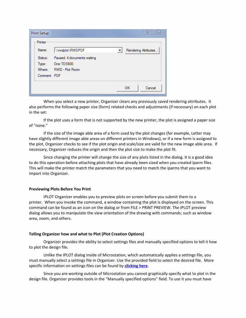
When you select a new printer, Organizer clears any previously saved rendering attributes. It
also performs the following paper size (form) related checks and adjustments (if necessary) on each plot in the set:
If the plot uses a form that is not supported by the new printer, the plot is assigned a paper size of "none."
If the size of the image able area of a form used by the plot changes (for example, Letter may have slightly different image able areas on different printers in Windows), or if a new form is assigned to the plot, Organizer checks to see if the plot origin and scale/size are valid for the new image able area. If necessary, Organizer reduces the origin and then the plot size to make the plot fit.
Since changing the printer will change the size of any plots listed in the dialog. It is a good idea to do this operation before attaching plots that have already been sized when you created iparm files. This will make the printer match the parameters that you need to match the iparms that you want to import into Organizer.
Previewing Plots Before You Print
IPLOT Organizer enables you to preview plots on screen before you submit them to a printer. When you invoke the command, a window containing the plot is displayed on the screen. This command can be found as an icon on the dialog or from FILE > PRINT PREVIEW. The IPLOT preview dialog allows you to manipulate the view orientation of the drawing with commands; such as window area, zoom, and others.
Telling Organizer how and what to Plot (Plot Creation Options)
Organizer provides the ability to select settings files and manually specified options to tell it how to plot the design file.
Unlike the IPLOT dialog inside of Microstation, which automatically applies a settings file, you must manually select a settings file in Organizer. Use the provided field to select the desired file. More specific information on settings files can be found by clicking here.
Since you are working outside of Microstation you cannot graphically specify what to plot in the design file. Organizer provides tools in the “Manually specified options” field. To use it you must have
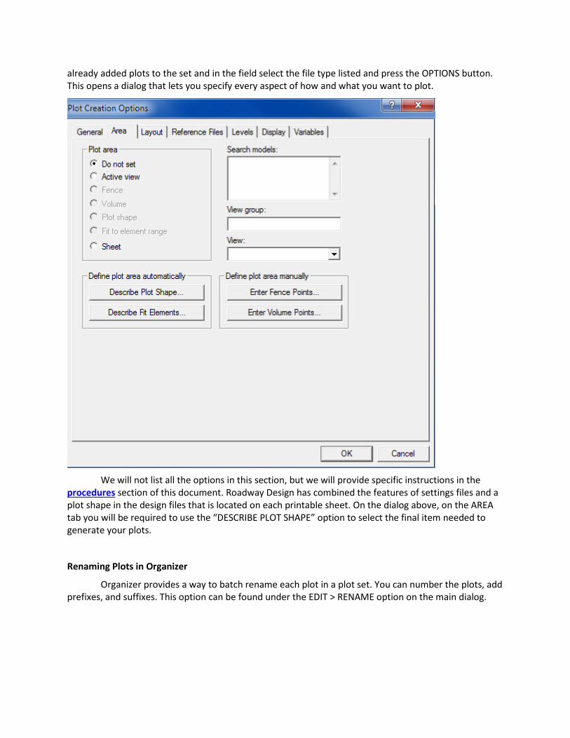
already added plots to the set and in the field select the file type listed and press the OPTIONS button. This opens a dialog that lets you specify every aspect of how and what you want to plot.
We will not list all the options in this section, but we will provide specific instructions in the procedures section of this document. Roadway Design has combined the features of settings files and a plot shape in the design files that is located on each printable sheet. On the dialog above, on the AREA tab you will be required to use the “DESCRIBE PLOT SHAPE” option to select the final item needed to generate your plots.
Renaming Plots in Organizer
Organizer provides a way to batch rename each plot in a plot set. You can number the plots, add prefixes, and suffixes. This option can be found under the EDIT > RENAME option on the main dialog.
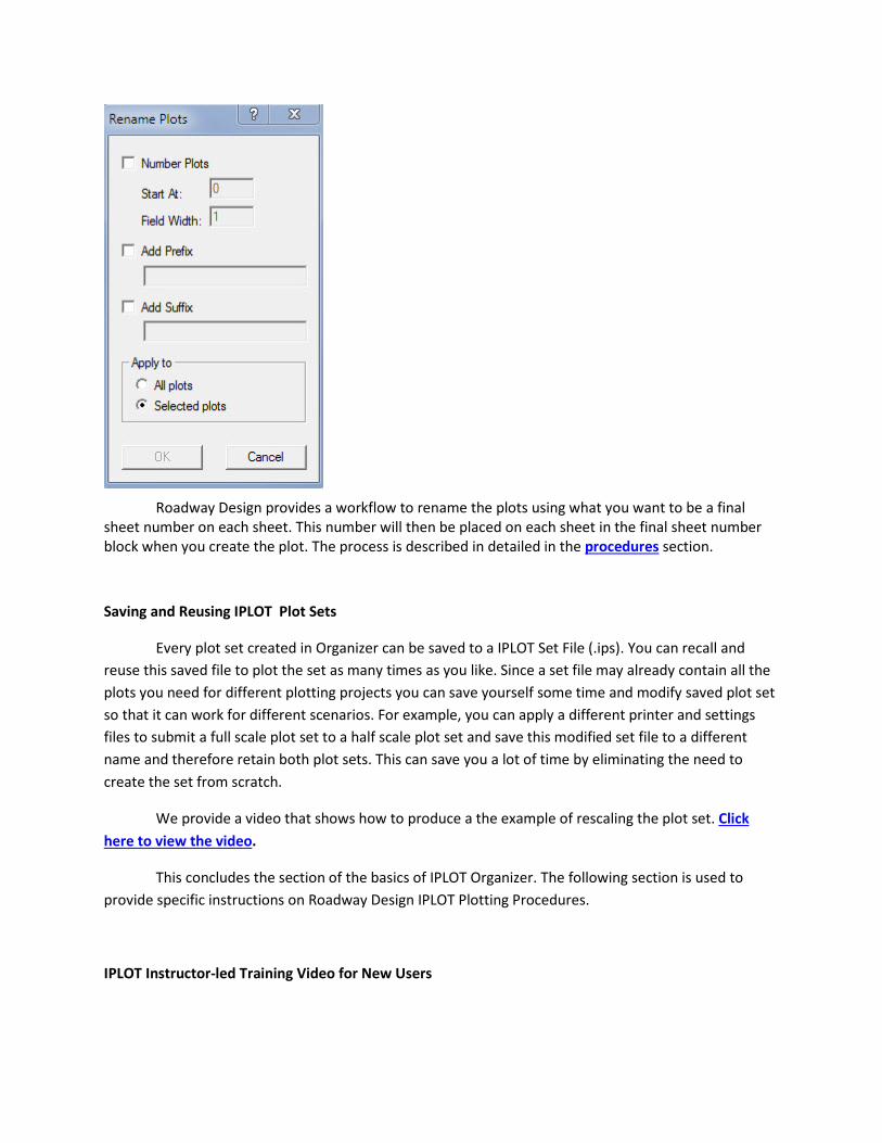
Roadway Design provides a workflow to rename the plots using what you want to be a final sheet number on each sheet. This number will then be placed on each sheet in the final sheet number block when you create the plot. The process is described in detailed in the procedures section.
Saving and Reusing IPLOT Plot Sets
Every plot set created in Organizer can be saved to a IPLOT Set File (.ips). You can recall and reuse this saved file to plot the set as many times as you like. Since a set file may already contain all the plots you need for different plotting projects you can save yourself some time and modify saved plot set so that it can work for different scenarios. For example, you can apply a different printer and settings files to submit a full scale plot set to a half scale plot set and save this modified set file to a different name and therefore retain both plot sets. This can save you a lot of time by eliminating the need to create the set from scratch.
We provide a video that shows how to produce a the example of rescaling the plot set. Click here to view the video.
This concludes the section of the basics of IPLOT Organizer. The following section is used to provide specific instructions on Roadway Design IPLOT Plotting Procedures.
IPLOT Instructor-led Training Video for New Users
Roadway Design has recorded an online instructor-led class showing how to use the basics of IPLOT plotting focusing on new users. This is a 2 ½-hour video located on our ftp site. It is recommended that you copy the video to your local computer before you watch it. To copy it click on the link below, click the wmw video file and SAVE a copy to your computer:
http://ftp.mdot.state.ms.us/ftp/Roadway_Design/RWD_Files/CADD_Training/Online-IPlot_New_Employee_Training/
IPLOT PLOTTING PROCEDURES
Creating IPLOT PDF plots
The following section describes in detail have to create a Roadway Design plan set in PDF format.
Creating a PDF with IPLOT inside Microstation
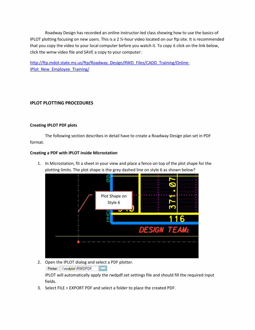
1. In Microstation, fit a sheet in your view and place a fence on top of the plot shape for the plotting limits. The plot shape is the grey dashed line on style 6 as shown below?
2. Open the IPLOT dialog and select a PDF plotter.
IPLOT will automatically apply the rwdpdf.set settings file and should fill the required input fields.
3. Select FILE > EXPORT PDF and select a folder to place the created PDF.
Plot Shape on Style 6
Creating a PDF Plot Set with IPLOT Organizer
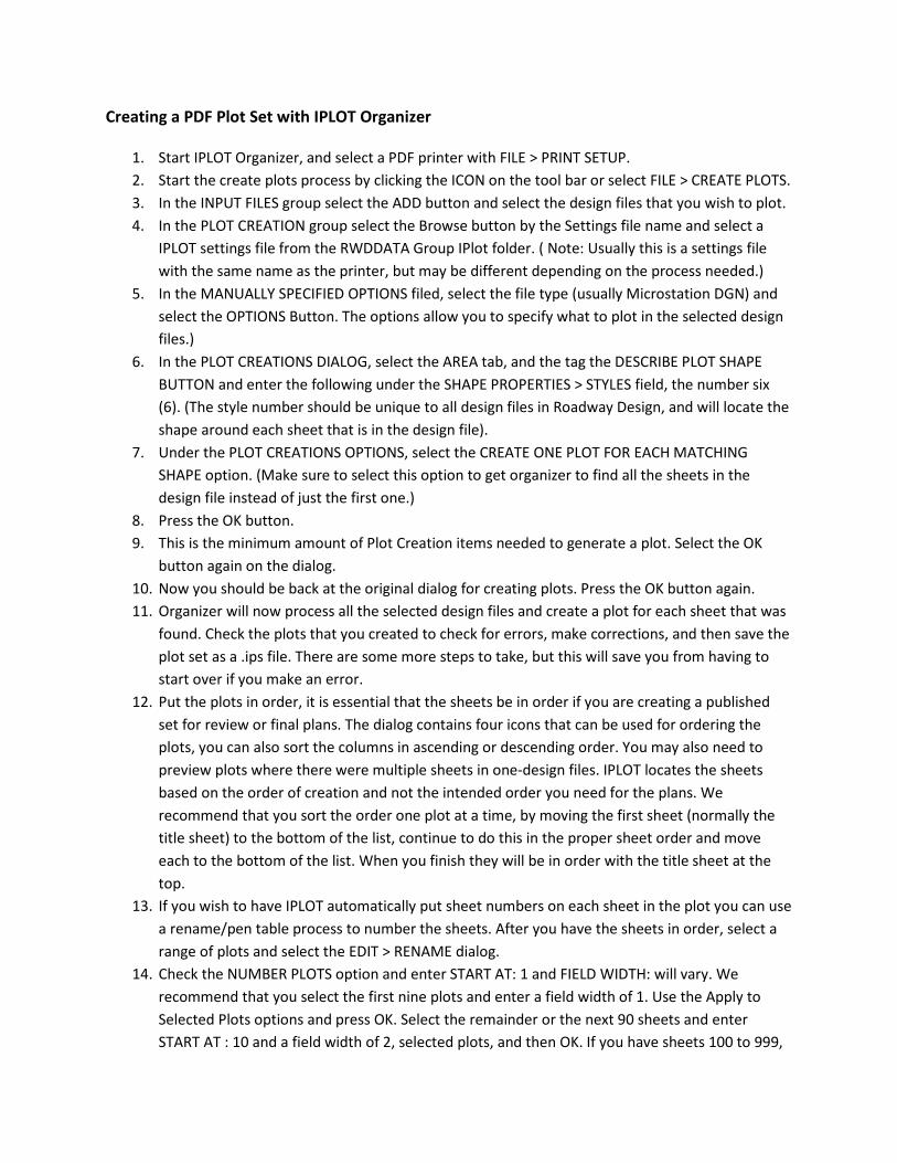
1. Start IPLOT Organizer, and select a PDF printer with FILE > PRINT SETUP. 2. Start the create plots process by clicking the ICON on the tool bar or select FILE > CREATE PLOTS. 3. In the INPUT FILES group select the ADD button and select the design files that you wish to plot. 4. In the PLOT CREATION group select the Browse button by the Settings file name and select a
IPLOT settings file from the RWDDATA Group IPlot folder. ( Note: Usually this is a settings file with the same name as the printer, but may be different depending on the process needed.)
5. In the MANUALLY SPECIFIED OPTIONS filed, select the file type (usually Microstation DGN) and select the OPTIONS Button. The options allow you to specify what to plot in the selected design files.)
6. In the PLOT CREATIONS DIALOG, select the AREA tab, and the tag the DESCRIBE PLOT SHAPE BUTTON and enter the following under the SHAPE PROPERTIES > STYLES field, the number six (6). (The style number should be unique to all design files in Roadway Design, and will locate the shape around each sheet that is in the design file).
7. Under the PLOT CREATIONS OPTIONS, select the CREATE ONE PLOT FOR EACH MATCHING SHAPE option. (Make sure to select this option to get organizer to find all the sheets in the design file instead of just the first one.)
8. Press the OK button. 9. This is the minimum amount of Plot Creation items needed to generate a plot. Select the OK
button again on the dialog. 10. Now you should be back at the original dialog for creating plots. Press the OK button again. 11. Organizer will now process all the selected design files and create a plot for each sheet that was
found. Check the plots that you created to check for errors, make corrections, and then save the plot set as a .ips file. There are some more steps to take, but this will save you from having to start over if you make an error.
12. Put the plots in order, it is essential that the sheets be in order if you are creating a published set for review or final plans. The dialog contains four icons that can be used for ordering the plots, you can also sort the columns in ascending or descending order. You may also need to preview plots where there were multiple sheets in one-design files. IPLOT locates the sheets based on the order of creation and not the intended order you need for the plans. We recommend that you sort the order one plot at a time, by moving the first sheet (normally the title sheet) to the bottom of the list, continue to do this in the proper sheet order and move each to the bottom of the list. When you finish they will be in order with the title sheet at the top.
13. If you wish to have IPLOT automatically put sheet numbers on each sheet in the plot you can use a rename/pen table process to number the sheets. After you have the sheets in order, select a range of plots and select the EDIT > RENAME dialog.
14. Check the NUMBER PLOTS option and enter START AT: 1 and FIELD WIDTH: will vary. We recommend that you select the first nine plots and enter a field width of 1. Use the Apply to Selected Plots options and press OK. Select the remainder or the next 90 sheets and enter START AT : 10 and a field width of 2, selected plots, and then OK. If you have sheets 100 to 999,
repeat the process for those. You do not have to do exact counts of sheets, because you can always adjust the numbers later if you miscounted or just guessed. In the end you want to have the exact number for the required sheet number in the PLOT NAME column. This number will get copied to the generated plot. (NOTE: for this process to work, you must have the text ($PG$) located in the sheet number block of every sheet in the design file).
15. Apply color to Plan/Profile sheets. First, select only plan profile sheets in the Organizer dialog. 16. Right-Click on the selected plots and select PROPERTIES. 17. Select the GENERAL tab in the dialog. 18. Under the MICROSTATION PEN TABLE field, select the BROWSE button and select a pen table
that will apply the Roadway Color scheme to the plots. These are located in the RWDDATA Group PenTables folder. The pen table you select may change over time. Use the pen table that is designed to produce the colors. (Note: There may be one that produces preliminary plots and one to produce final plans).
19. Press the OK button to apply the pen table to the selected plan/profile sheets. 20. To apply the number plot names to each plot, select all the files and right click to select
PROPERTIES. 21. Select the GENERAL tab in the dialog. 22. Under RESYMBOLIZATION FILE, check the DESIGN SCRIPT box and in the file name field use the
BROWSE button to locate the RWDDATA Iplot DesignScript folder and select the proper script to number the plot. Use the script that is designed to do final page numbers.
23. Press the OK button to apply the script to all files. 24. It is now recommended that you spot check or preview a few plots to check for errors and make
corrections. RESAVE the .ips file. Things to check for: a. Check the quality of the plot and make sure the plot encompasses the entire sheet. b. Ensure all data is present (levels, references, etc.) c. Check plot rotation d. Check plan/profile sheets for colors.
25. Create the final single multi-page PDF file, Press the PDF icon or FILE > EXPORT PDF… There is a standard process in place for the name of the PDF file. Click here to see the details.
26. In the EXPORT PDF dialog, check your plot range, make sure to CREATE ONE PDF CONTAINING ALL PLOTS, and press the PDF FORMAT CONFIGURATION button.
27. In the format configuration dialog, we currently recommend the following settings: Resolution: 400 or 600 dpi (we recommend 600 dpi) Version: Changes over time (we recommend one version prior to the latest version) Searchable Text: turned on or checked Levels/Files (Optional Content) (we recommend that the be turned off or unchecked) RGB JPEG Compression (turned on by default) Disable Saved Views/References Bookmark (turned on by default)
Note: After initial settings are they are saved, but only on the computer you are working on. Press OK to set and close the format dialog.
28. You can now create the PDF file by pressing the CREATE PDF button. (Note: that you can check the “Invoke PDF Viewer when done” option if you want to open and view the created pdf.)
PDF Video – A detailed video is available showing the process of creating PDF files using IPLOT. You can click on this link to view the video.
IPLOT Organizer can be used to plot hardcopies directly to plotters as well. The processes are similar to PDF other than you do not export to a PDF file.
Standard PDF File Names
The individual sheet plot names have to be renamed to use the sheet numbering procedure, but the single PDF must conform to the following standard names: FMSNUMBER -Date-Print Type.PDF Examples are below. Note that each Final ROW revision requires 2 documents to be submitted, one with only revisions, and the other with the most current ROW plans. Cross Sections should be submitted in separate multi-page files.
Examples for each print type:
100078-201000-2009-04-05-HydraulicSurvey.PDF
100078-201000-2009-04-05-Conceptual.PDF
100078-201000-2009-09-05- PreROW.PDF
100078-201000-2009-11-05-FI.PDF
100078-201000-2010-01-08-FinalROW.PDF
100078-201000-2010-01-08-FinalROWXS.PDF
First ROW Revision 100078-201000-2010-02-03-FinalROW.PDF (Contains all sheets and the revisions – This creates a current set of plans with the Revisions included.) 100078-201000-2010-02-03-FinalROWRev.PDF (Contains Title Sheet & just revised sheets only in the multi-page pdf.)
Second ROW Revision 100078-201000-2010-04-08-FinalROW.PDF (Contains all sheets and the revisions – This creates a current set of plans with the Revisions included.) 100078-201000-2010-04-08-FinalROWRev.PDF (Contains Title Sheet & just revised sheets only in the multi-page pdf.)
100078-301000-2010-11-10-OfficeReview.PDF
100078-301000-2010-11-10-FinalXS.PDF
Notes: a) IT IS CRITICAL TO HAVE THE FILES IN ORDER (SHEET ORDER) in the multi-page
document and for automatic numbering. b) The FMSNumber should be 13 characters (100078-201000) and should be the ROW
FMS # for ROW related plans & the Construction FMS # for all plans printed for Office Review & Final Plans.
c) The Date should be a date close to the actual print request or the actual date of a revision.
IPLOT Settings Files
IPLOT setting files are used to pre-set some of the options that are normally done manually in the Dialog Interface or in Iplot Organizer.
If you frequently use standard sets of parameters, it rapidly becomes tedious to re-specify these each time you submit a plot. Therefore, you can use an IPLOT "settings file" that enables you to specify groups of parameters for repeated use.
Below is an example of common settings that can put in this file:
-workspace_user = rwdeast -paper_size="11x17" -units=in -rotation=0 -color_table=gr:bw.ctb -ysize=10.5 -pen_table=gr:datestamp.pen -update
The key words listed above can be found in the IPLOT Help Document under "Introducing the IPLOT Command Line"
IPLOT Resources and Non-Standard IPLOT Plotting
When receiving design files or AutoCad files from outside sources you might discover that the files contain non-standard items, such as; different fonts or line styles. To get these to plot correctly you must have access to the resources that were used to create the original design files.
Our workspace files in the department are now read-only, which will no longer allow us make local workspace changes to compensate. To get around this problem, we are now providing their font resource files directly in our dataset.
If the file was designed and drawn by either Traffic or Geo Tec division, users may not be able to
plot them correctly due to the fact that they use different font resources. The necessary resources are located in these folders:

…\rwddata\group\fonts\TrafficFonts\ …\rwddata\group\fonts\GeoTecFonts\ To use these resources during plotting, you can manually specify a user configuration file that will point to the font resources located in one of the previously listed folders (See the WORKSPACE section in the file for more information on the user config files). When plotting, select one of the user configuration names below: TrafficFonts : use Traffic Division fonts when plotting the file GeoTecFonts : use Geo Tec Division fonts when plot the file Important Note: The user configuration files above should probably only be used when plotting and not for viewing the files, but it is possible to manually select these user config files in Microstation Manager when opening one of these divisions’ files. This will allow you to view them with their font’s active, but be aware that we do not provide any associated preferences. Thus, the design file will NOT open with our menus opened and docked as you would expect. You may also get an error message about items not being found due to this issue. This is a buggy aspect that occurs in Microstation when it tries to auto-create a new set of user preferences. Switching to a set of Microstation preferences that are so adverse to ours has a bad side effect of messing up your docked menus when you return to using the normal RWD user workspace and preferences. This scenario is really only good for viewing the file and not so good for doing any work. Due to the side-effects it is recommended that you only use them to plot.
If the resources needed are not listed under the groups folder you will have to convert the drawing so that it uses standard Roadway resources. Fonts and line styles are controlled by the Microstation workspace configuration. The workspace has variables that point to the locations of these resource files. If plotting within Microstation, you will not have to specify the Roadway Design workspace to be used, but in Iplot Organizer you may have to specify the workspace name to use on the General tab. This is usually automated via the Iplot set files.
Below is a list of our current Microstation resources:
Font Resource files are located in ...\rwddata\group\fonts\ and...\rwddata\mgroup
Line Style Resource files are located in ...\rwddata\group\linestyles\ and ...\rwddata\mgroup
Microstation Workspace configuration files are located in ...\rwddata\workspace\
In addition to these resource files, there are some resource files that we generally do not use on our projects, but are needed for special projects.
Standard Drawings:
Our standard drawings were not created by Roadway Design. A outside source was selected to create our standard drawings in Microstation design file format. This outside source decided on their own to create and use a few additional resource files. The names and descriptions are below:
cacadlst.rsc : A line style resource of which I do not know the source.
acadlsty.rsc : A default resource file included with Microstation.
lstyle.rsc : Another default resource file included with Microstation.
IPLOT Software Custom Configuration Files
The IPLOT client software loaded on the individual computers uses configuration files that tell the software were to for files such as settings files, resources, and how to perform certain plotting actions. Roadway Design has customized these files and they must be installed in order for many of the features depicted in this chapter to work as designed.
CADD support will make an effort to install these files when your computer is delivered or updated. If the files are not delivered you can install then yourself. This is done with small programs that can be found on your desktop folders.
To install the correct version of IPLOT Configuration files, follow these instructions:
1. Locate the folder _RWD_APPS_ on your desktop and open it. 2. In this folder, locate the sub folder labeled APPS FOR RWD ONLY and open it. 3. Locate the sub folder labeled IPLOT_CONFIGURE and open it.
This folder contains the custom IPLOT configuration files than need to be copied to the IPLOT software folders. To do this you will double-click one of the following batch file programs:
Install_IPLOT_English_CFG.bat – use this to install the config files on a 32-bit OS Windows computer.
Install_IPLOT_English_CFG_64bit.bat – use this file instead if your computer is 64-bit OS.
The other two batch files are run if you are working on a METRIC project. (Note: Remember to run the English or metric batch files each time you switch between these projects.)
A text file is available in this folder for instructions if you do not want to refer back to this chapter.
When you run the batch file a command window will open showing you the results of the copy process. You should be able to determine from the message if it was successful or not, if not see your CADD Support. Hit the ENTER key to close the command window.
Roadway Design Plotter Hardware Guide
Oce' TDS600
The Oce' TDS600 is a black and white plotting device. It was obtained for the purpose of plotting full scale and half scale work sheets and design drawings. It is configured to plot on 36 inch and 18 inch wide paper. The paper size the plots come out on are controlled by the size of the plot submitted. With the scanner attachment you can also make hard and electronic raster copies of large format drawings.
Printer queues are set as follows on Plot Server RWDPLOT
Hard prints that are submitted to this plot server use a Oce' TDS600 driver. After the print has been processed it is sent directly to the Oce' TDS600 Controller Server which sends the file to the plotter.
This printer is also used for its print sizes and configurations. The custom print sizes or forms are used to help generate PDF files using IPLOT and the printer name RWDPDF.
Oce' Colorwave
The Oce' Colorwave is a color plotting device. Its main purpose is to provide the Plan Room the ability to make hard copies of large format drawings but is will also be used to plot full scale and half scale work sheets and design drawings. It can generate both black & white and color drawings. It is configured to plot on 36 inch and 18 inch wide paper. The paper size the plots come out on are controlled by the size of the plot submitted.
Printer queues are set as follows on Plot Server RWDSRVPLOT
All prints that are submitted to this plot server use a Oce' ColorWave driver. After the print has been processed it is sent directly to the Oce' Colorwave Controller which is built into the plotter. The controller settings can be accessed by typing 10.1.40.10 in a web browser.
HP 5500
The HP 5500 is a color plotting device. Its purpose is to provide the ability to plot large format color prints up to 42 inches wide. It is used mainly to produce large aerial photos, maps, and color presentations.
Printer queues are available on the Plot Server RWDPLOT
HPT 1120
The HPT 1120 is a color plotting and scanning device. Its purpose is to provide the ability scan large format color prints. The scans can be sent to file or printed on the device as a copy. It is used mainly to copy large aerial photos, maps, and color presentations. Typically it can print faster than the HP 5500, but usually the quality may not be as good.
Printer queues are available on the Plot Server RWDPLOT
Laser Printers
There are various types of Laser Printers positioned through-out the department. Use the description associated with the names of these printers to help determine which ones to connect. These printers are serviced through one of the following plot servers; RWDPLOT or RWDSRVPLOT. Some laser printers support color, but most support only black and white. Most have the ability to plot at sizes (12x18, 11x17, & 8 ½ x 11).
See CADD SUPPORT for information regarding these printers.
MICROSTATION PRINTING (MPLOT) PROCEDURES
Introduction
This section is designed to help users that use Microstation only to plot (Non-IPLOT). This section of the help includes information about Microstation plot drivers (.pltcfg) files. Some of these were created to help emulate the appearance of graphics printed with Iplot and the creation of PDF/Tiff files.
Roadway Design Plot Drivers (PLTCFG)
Roadway Design has created some MicroStation Plotter Configuration template driver files that can be used to emulate Roadway Design plotting. The files may need editing to comply with some of your local printing abilities. The files are located in the supplied RWD/Group directories. Instructions for each are listed below, but you can also find instructions inside each file. These are XML based file types and can only be viewed and edited within Microstation Printing Interface. To view or edit the settings of the plot configuration files click on FILE > PRINT. In the Printer Dialog, click the GENERAL tab to get a description of the driver.
1A. RWDPDF.PLTCFG
USE PRIMARILY TO PLOT TO PDF (BLACK & WHITE - MONOCHROME) This plot driver configuration file generates a PDF (Portable Document File). The file is created by default in the same directory as the source dgn file, except with a .pdf extension.
The PDF generated can be opened with Adobe Reader 7 (PDF 1.6) or higher. If you require that the PDF be opened with an older Reader version you can change this under the tab, Base Properties -> Driver Properties -> PDF Version. Some properties of the PDF may be negated if older versions are selected. The notable Base Properties are listed below, we recommend that you leave these set to (On): Engineering Links (On) : If your dgn elements contain a web link, that link transfers to the PDF file. Searchable Text (On): Text elements in the dgn will be searchable in the PDF file. Plot to 3D (On): If your dgn file is 3D you can transfer the 3D content to the PDF file. Optional Content (Off): All the levels and references in the dgn file ARE NOT transferred to the PDF by default. You are allowed to turn it on, but it could significantly slow the plotting process. The plotted weights generated are set to emulate the weights produced by a 400 dpi plotter using IPlot software. The PDF file is also generated at 400 dpi. This dpi setting was selected to reduce file size and still get reasonable resolution quality. Since this config file does send the file to a system printer it allows you to set paper sizes. The sizes that have been set are standard for printing Roadway sheet sizes of Full (34.6 x 22) and Half (17.3x11) and the other common sizes of letter, legal, and 11 x 17. The color output is defaulted to black & white - monochrome. You can plot to color by changing to color on the main dialog window or by changing Base Properties > General > Default Color Mode. The pen table (stamp.tbl) is attached to replace text with a date and filename. It is assumed that you will be plotting a sheet cell. If no sheet cell is used it is not necessary to detach the pen table unless you want to use your own pen table. If you do not want anyone to be able to modify or print the outputted PDF file you will can modify the settings under Base Properties > Driver Properties features for "Allow Changes" and "Allow Printing".
1B. RWDPDFXS.PLTCFG
WAS USED PRIMARILY TO PLOT CROSS SECTION SHEETS TO PDF (BLACK & WHITE - MONOCHROME) This plot driver is currently the same as RWDPDF.PLTCFG. At one time it was different in that it would not produce the levels and files in the PDF. This was a necessary to prevent long processing times it took to produce the large number of reference in a cross section file. This has also been turned off in RWDPDF.PLTCFG.
1B. RWDPDF_COLOR.PLTCFG
USE TO PLOT COLORIZED PLAN PROFILE SHEETS TO PDF (TRUE COLOR) This plot driver configuration file generates a PDF (Portable Document File). The file is created by default in the same directory as the source dgn file, except with a .pdf extension.
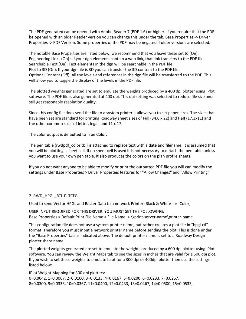
The PDF generated can be opened with Adobe Reader 7 (PDF 1.6) or higher. If you require that the PDF be opened with an older Reader version you can change this under the tab, Base Properties -> Driver Properties -> PDF Version. Some properties of the PDF may be negated if older versions are selected. The notable Base Properties are listed below, we recommend that you leave these set to (On): Engineering Links (On) : If your dgn elements contain a web link, that link transfers to the PDF file. Searchable Text (On): Text elements in the dgn will be searchable in the PDF file. Plot to 3D (On): If your dgn file is 3D you can transfer the 3D content to the PDF file. Optional Content (Off): All the levels and references in the dgn file will be transferred to the PDF. This will allow you to toggle the display of the levels in the PDF file. The plotted weights generated are set to emulate the weights produced by a 400 dpi plotter using IPlot software. The PDF file is also generated at 400 dpi. This dpi setting was selected to reduce file size and still get reasonable resolution quality. Since this config file does send the file to a system printer it allows you to set paper sizes. The sizes that have been set are standard for printing Roadway sheet sizes of Full (34.6 x 22) and Half (17.3x11) and the other common sizes of letter, legal, and 11 x 17. The color output is defaulted to True Color. The pen table (rwdpdf_color.tbl) is attached to replace text with a date and filename. It is assumed that you will be plotting a sheet cell. If no sheet cell is used it is not necessary to detach the pen table unless you want to use your own pen table. It also produces the colors on the plan profile sheets. If you do not want anyone to be able to modify or print the outputted PDF file you will can modify the settings under Base Properties > Driver Properties features for "Allow Changes" and "Allow Printing".
2. RWD_HPGL_RTL.PLTCFG
Used to send Vector HPGL and Raster Data to a network Printer (Black & White -or- Color)
USER INPUT REQUIRED FOR THIS DRIVER. YOU MUST SET THE FOLLOWING: Base Properties > Default Print File Name > File Name: < \\print-server-name\printer-name
This configuration file does not use a system printer name, but rather creates a plot file in "hpgl-rtl" format. Therefore you must input a network printer name before sending the plot. This is done under the "Base Properties" tab as indicated above. The default printer name is set to a Roadway Design plotter share name.
The plotted weights generated are set to emulate the weights produced by a 600 dpi plotter using IPlot software. You can review the Weight Maps tab to see the sizes in inches that are valid for a 600 dpi plot. If you wish to set these weights to emulate Iplot for a 300 dpi or 400dpi plotter then use the settings listed below:
IPlot Weight Mapping for 300 dpi plotters: 0=0.0042, 1=0.0067, 2=0.0100, 3=0.0133, 4=0.0167, 5=0.0200, 6=0.0233, 7=0.0267, 8=0.0300, 9=0.0333, 10=0.0367, 11=0.0400, 12=0.0433, 13=0.0467, 14=0.0500, 15=0.0533,
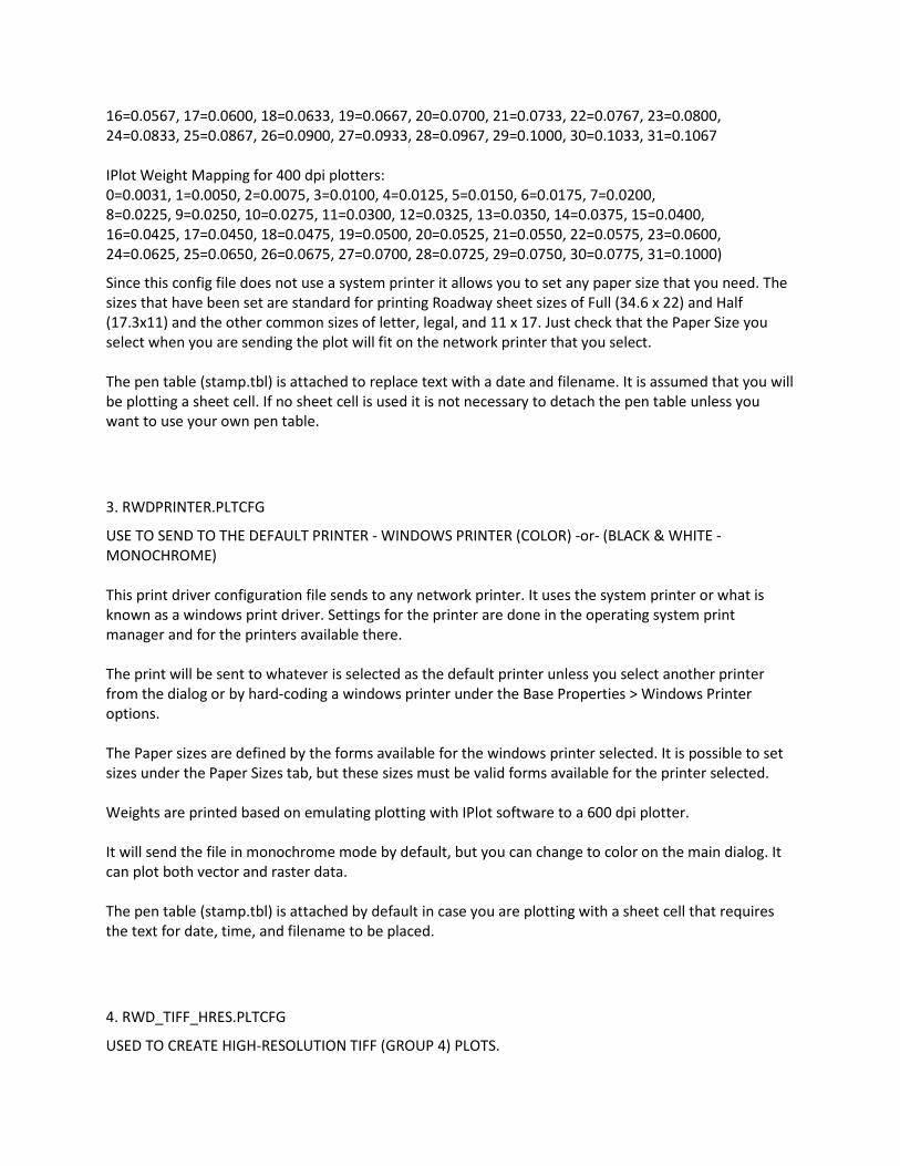
16=0.0567, 17=0.0600, 18=0.0633, 19=0.0667, 20=0.0700, 21=0.0733, 22=0.0767, 23=0.0800, 24=0.0833, 25=0.0867, 26=0.0900, 27=0.0933, 28=0.0967, 29=0.1000, 30=0.1033, 31=0.1067 IPlot Weight Mapping for 400 dpi plotters: 0=0.0031, 1=0.0050, 2=0.0075, 3=0.0100, 4=0.0125, 5=0.0150, 6=0.0175, 7=0.0200, 8=0.0225, 9=0.0250, 10=0.0275, 11=0.0300, 12=0.0325, 13=0.0350, 14=0.0375, 15=0.0400, 16=0.0425, 17=0.0450, 18=0.0475, 19=0.0500, 20=0.0525, 21=0.0550, 22=0.0575, 23=0.0600, 24=0.0625, 25=0.0650, 26=0.0675, 27=0.0700, 28=0.0725, 29=0.0750, 30=0.0775, 31=0.1000)
Since this config file does not use a system printer it allows you to set any paper size that you need. The sizes that have been set are standard for printing Roadway sheet sizes of Full (34.6 x 22) and Half (17.3x11) and the other common sizes of letter, legal, and 11 x 17. Just check that the Paper Size you select when you are sending the plot will fit on the network printer that you select. The pen table (stamp.tbl) is attached to replace text with a date and filename. It is assumed that you will be plotting a sheet cell. If no sheet cell is used it is not necessary to detach the pen table unless you want to use your own pen table.
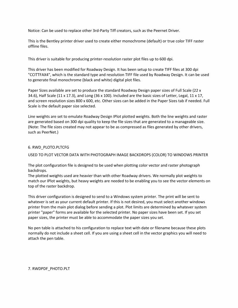
3. RWDPRINTER.PLTCFG
USE TO SEND TO THE DEFAULT PRINTER - WINDOWS PRINTER (COLOR) -or- (BLACK & WHITE - MONOCHROME) This print driver configuration file sends to any network printer. It uses the system printer or what is known as a windows print driver. Settings for the printer are done in the operating system print manager and for the printers available there. The print will be sent to whatever is selected as the default printer unless you select another printer from the dialog or by hard-coding a windows printer under the Base Properties > Windows Printer options. The Paper sizes are defined by the forms available for the windows printer selected. It is possible to set sizes under the Paper Sizes tab, but these sizes must be valid forms available for the printer selected. Weights are printed based on emulating plotting with IPlot software to a 600 dpi plotter. It will send the file in monochrome mode by default, but you can change to color on the main dialog. It can plot both vector and raster data. The pen table (stamp.tbl) is attached by default in case you are plotting with a sheet cell that requires the text for date, time, and filename to be placed.
4. RWD_TIFF_HRES.PLTCFG
USED TO CREATE HIGH-RESOLUTION TIFF (GROUP 4) PLOTS.
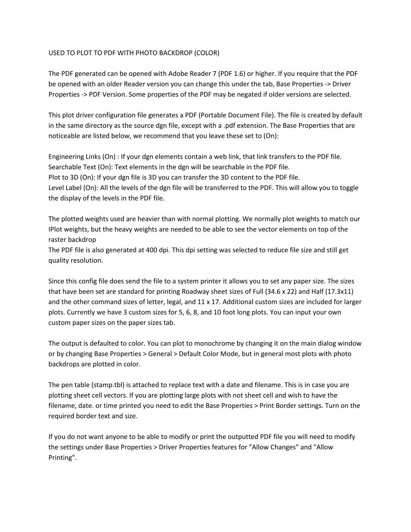
Notice: Can be used to replace other 3rd-Party Tiff creators, such as the Peernet Driver. This is the Bentley printer driver used to create either monochrome (default) or true color TIFF raster offline files.
This driver is suitable for producing printer-resolution raster plot files up to 600 dpi. This driver has been modified for Roadway Design. It has been setup to create TIFF files at 300 dpi "CCITTFAX4", which is the standard type and resolution TIFF file used by Roadway Design. It can be used to generate final monochrome (black and white) digital plot files. Paper Sizes available are set to produce the standard Roadway Design paper sizes of Full Scale (22 x 34.6), Half Scale (11 x 17.3), and Long (36 x 100). Included are the basic sizes of Letter, Legal, 11 x 17, and screen resolution sizes 800 x 600, etc. Other sizes can be added in the Paper Sizes tab if needed. Full Scale is the default paper size selected. Line weights are set to emulate Roadway Design IPlot plotted weights. Both the line weights and raster are generated based on 300 dpi quality to keep the file sizes that are generated to a manageable size. (Note: The file sizes created may not appear to be as compressed as files generated by other drivers, such as PeerNet.)
6. RWD_PLOTO.PLTCFG
USED TO PLOT VECTOR DATA WITH PHOTOGRAPH IMAGE BACKDROPS (COLOR) TO WINDOWS PRINTER The plot configuration file is designed to be used when plotting color vector and raster photograph backdrops. The plotted weights used are heavier than with other Roadway drivers. We normally plot weights to match our IPlot weights, but heavy weights are needed to be enabling you to see the vector elements on top of the raster backdrop. This driver configuration is designed to send to a Windows system printer. The print will be sent to whatever is set as your current default printer. If this is not desired, you must select another windows printer from the main plot dialog before sending a plot. Plot limits are determined by whatever system printer "paper" forms are available for the selected printer. No paper sizes have been set. If you set paper sizes, the printer must be able to accommodate the paper sizes you set. No pen table is attached to his configuration to replace text with date or filename because these plots normally do not include a sheet cell. If you are using a sheet cell in the vector graphics you will need to attach the pen table.
7. RWDPDF_PHOTO.PLT
USED TO PLOT TO PDF WITH PHOTO BACKDROP (COLOR) The PDF generated can be opened with Adobe Reader 7 (PDF 1.6) or higher. If you require that the PDF be opened with an older Reader version you can change this under the tab, Base Properties -> Driver Properties -> PDF Version. Some properties of the PDF may be negated if older versions are selected. This plot driver configuration file generates a PDF (Portable Document File). The file is created by default in the same directory as the source dgn file, except with a .pdf extension. The Base Properties that are noticeable are listed below, we recommend that you leave these set to (On): Engineering Links (On) : If your dgn elements contain a web link, that link transfers to the PDF file. Searchable Text (On): Text elements in the dgn will be searchable in the PDF file. Plot to 3D (On): If your dgn file is 3D you can transfer the 3D content to the PDF file. Level Label (On): All the levels of the dgn file will be transferred to the PDF. This will allow you to toggle the display of the levels in the PDF file. The plotted weights used are heavier than with normal plotting. We normally plot weights to match our IPlot weights, but the heavy weights are needed to be able to see the vector elements on top of the raster backdrop The PDF file is also generated at 400 dpi. This dpi setting was selected to reduce file size and still get quality resolution. Since this config file does send the file to a system printer it allows you to set any paper size. The sizes that have been set are standard for printing Roadway sheet sizes of Full (34.6 x 22) and Half (17.3x11) and the other command sizes of letter, legal, and 11 x 17. Additional custom sizes are included for larger plots. Currently we have 3 custom sizes for 5, 6, 8, and 10 foot long plots. You can input your own custom paper sizes on the paper sizes tab. The output is defaulted to color. You can plot to monochrome by changing it on the main dialog window or by changing Base Properties > General > Default Color Mode, but in general most plots with photo backdrops are plotted in color. The pen table (stamp.tbl) is attached to replace text with a date and filename. This is in case you are plotting sheet cell vectors. If you are plotting large plots with not sheet cell and wish to have the filename, date. or time printed you need to edit the Base Properties > Print Border settings. Turn on the required border text and size. If you do not want anyone to be able to modify or print the outputted PDF file you will need to modify the settings under Base Properties > Driver Properties features for "Allow Changes" and "Allow Printing".
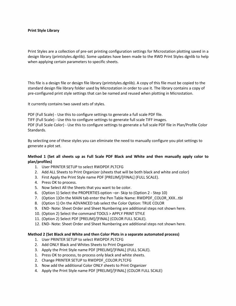
Print Style Library
Print Styles are a collection of pre-set printing configuration settings for Microstation plotting saved in a design library (printstyles.dgnlib). Some updates have been made to the RWD Print Styles dgnlib to help when applying certain parameters to specific sheets.
This file is a design file or design file library (printstyles.dgnlib). A copy of this file must be copied to the standard design file library folder used by Microstation in order to use it. The library contains a copy of pre-configured print style settings that can be named and reused when plotting in Microstation.
It currently contains two saved sets of styles.
PDF (Full Scale) - Use this to configure settings to generate a full scale PDF file. TIFF (Full Scale) - Use this to configure settings to generate full scale TIFF images. PDF (Full Scale Color) - Use this to configure settings to generate a full scale PDF file in Plan/Profile Color Standards.
By selecting one of these styles you can eliminate the need to manually configure you plot settings to generate a plot set.
Method 1 (Set all sheets up as Full Scale PDF Black and White and then manually apply color to plan/profiles)
1. User PRINTER SETUP to select RWDPDF.PLTCFG 2. Add ALL Sheets to Print Organizer (sheets that will be both black and white and color) 3. First Apply the Print Style name PDF [PRELIM]/[FINAL] (FULL SCALE). 4. Press OK to process. 5. Now Select All the Sheets that you want to be color. 6. (Option 1) Select the PROPERTIES option –or- Skip to (Option 2 - Step 10) 7. (Option 1)On the MAIN tab enter the Pen Table Name: RWDPDF_COLOR_XXX…tbl 8. (Option 1) On the ADVANCED tab select the Color Option: TRUE COLOR 9. END- Note: Sheet Order and Sheet Numbering are additional steps not shown here. 10. (Option 2) Select the command TOOLS > APPLY PRINT STYLE 11. (Option 2) Select PDF [PRELIM]/[FINAL] (COLOR FULL SCALE). 12. END- Note: Sheet Order and Sheet Numbering are additional steps not shown here.
Method 2 (Set Black and White and then Color Plots in a separate automated process)
1. User PRINTER SETUP to select RWDPDF.PLTCFG 2. Add ONLY Black and Whites Sheets to Print Organizer 3. Apply the Print Style name PDF [PRELIM]/[FINAL] (FULL SCALE). 1. Press OK to process, to process only black and white sheets. 2. Change PRINTER SETUP to RWDPDF_COLOR.PLTCFG 3. Now add the additional Color ONLY sheets to Print Organizer 4. Apply the Print Style name PDF [PRELIM]/[FINAL] (COLOR FULL SCALE)
5. Press OK to process. 6. END- Note: Sheet Order and Sheet Numbering are additional steps not shown here.
Microstation Printing PDF Creation Plotting Procedure
This describes the procedures that Districts and Consultants can use to generate a set of electronic print sets (PDF Images) from your project design files using a batch printing method within Microstation using Print Organizer.
The following links will activate a video that will give you a good basic understanding of how to do the batch plotting and creating PDF's.
To get the current PDF standard file names click here.
To view an Instructional Video of how to create PDF files with Microstation, click the following link: Microstation V8i Print Organizer video.
Microstation Print Organizer Instructor-led video Class
Roadway Design has recorded an Instructor-led Microstation Print Organizer Class. This class gives an overall session on how to use the features of Print Organizer. Users can interactively use lab data along with class to learn how to use the skills learned in the course. The following links can be used to access the lab data and video.
The Lab Data is located on a FTP Server. The lab data is not required to take the class, but is recommended. To take the course with the lab data, you should first download the data from the following link (use the README.TXT file on the ftp site for downloading instructions):
http://ftp.mdot.state.ms.us/ftp/Roadway_Design/RWD_Files/CADD_Training/Online-Print_Organizer_Class
The video of the class is located on the MDOT TV site. You can view the video from a line on this page. Once you reach the line below, locate the TRAINING link and then the video with the title “MICROSTATION PRINT ORGANIZER”, and click the link next to it to view the video.
http://mdottv.mdot.state.ms.us/