TABLE OF CONTENTS - dec.state.ny.us · GAC slurry metering pump Hydraulic Spreader Barge...
23
ONONDAGA LAKE CAPPING FIELD DEMONSTRATION WORK PLAN PARSONS P:\Honeywell -SYR\446807 - Lake Capping Field Demo\09 Reports\9.1 work plan (446389)\Final Work Plan\Demonstration Capping Workplan 101811 final.docx October 20, 2011 i TABLE OF CONTENTS Page LIST OF ACROYNYMS ................................................................................................ iii SECTION 1 INTRODUCTION................................................................................... 1-1 1.1 FIELD DEMONSTRATION LOCATION ....................................................... 1-1 1.2 CONTENTS OF THIS WORK PLAN .............................................................. 1-2 SECTION 2 FIELD ACTIVITIES .............................................................................. 2-1 2.1 MOBILIZATION AND SITE PREPARATION............................................... 2-1 2.1.1 Mobilization ............................................................................................ 2-1 2.1.2 Stormwater/Erosion Control .................................................................... 2-2 2.1.3 Road Upgrades ........................................................................................ 2-3 2.1.4 Site Clearing ............................................................................................ 2-3 2.1.5 Support Area ............................................................................................ 2-3 2.2 MATERIAL TRANSPORT .............................................................................. 2-3 2.3 MATERIAL STAGING .................................................................................... 2-3 2.4 CAP MATERIAL MIXING AND DELIVERY SYSTEM CONSTRUCTION ............................................................................................ 2-3 2.4.1 Sand Feed System.................................................................................... 2-4 2.4.2 Carbon (GAC) Feed System .................................................................... 2-4 2.4.3 Sand/GAC Slurry Mix Tank .................................................................... 2-4 2.4.4 Slurry Line ............................................................................................... 2-4 2.4.5 Spreader Barge ........................................................................................ 2-5 2.4.6 Demarcation System ................................................................................ 2-5 2.5 CAP PLACEMENT FIELD DEMONSTRATION ........................................... 2-6 2.5.1 Demonstration Procedures ....................................................................... 2-6 2.5.2 Verification Sampling and Analysis ........................................................ 2-7 2.5.3 Water Quality Sampling .......................................................................... 2-8 2.5.4 Current Velocity and Wave Height Measurement .................................. 2-9 2.6 REPORTING ..................................................................................................... 2-9
-
Upload
duonghuong -
Category
Documents
-
view
216 -
download
0
Transcript of TABLE OF CONTENTS - dec.state.ny.us · GAC slurry metering pump Hydraulic Spreader Barge...

ONONDAGA LAKE
CAPPING FIELD DEMONSTRATION WORK PLAN
PARSONS
P:\Honeywell -SYR\446807 - Lake Capping Field Demo\09 Reports\9.1 work plan (446389)\Final Work Plan\Demonstration Capping Workplan 101811 final.docx
October 20, 2011
i
TABLE OF CONTENTS
Page
LIST OF ACROYNYMS ................................................................................................ iii
SECTION 1 INTRODUCTION................................................................................... 1-1
1.1 FIELD DEMONSTRATION LOCATION ....................................................... 1-1
1.2 CONTENTS OF THIS WORK PLAN .............................................................. 1-2
SECTION 2 FIELD ACTIVITIES .............................................................................. 2-1
2.1 MOBILIZATION AND SITE PREPARATION ............................................... 2-1
2.1.1 Mobilization ............................................................................................ 2-1
2.1.2 Stormwater/Erosion Control .................................................................... 2-2
2.1.3 Road Upgrades ........................................................................................ 2-3
2.1.4 Site Clearing ............................................................................................ 2-3
2.1.5 Support Area ............................................................................................ 2-3
2.2 MATERIAL TRANSPORT .............................................................................. 2-3
2.3 MATERIAL STAGING .................................................................................... 2-3
2.4 CAP MATERIAL MIXING AND DELIVERY SYSTEM
CONSTRUCTION ............................................................................................ 2-3
2.4.1 Sand Feed System .................................................................................... 2-4
2.4.2 Carbon (GAC) Feed System .................................................................... 2-4
2.4.3 Sand/GAC Slurry Mix Tank .................................................................... 2-4
2.4.4 Slurry Line ............................................................................................... 2-4
2.4.5 Spreader Barge ........................................................................................ 2-5
2.4.6 Demarcation System ................................................................................ 2-5
2.5 CAP PLACEMENT FIELD DEMONSTRATION ........................................... 2-6
2.5.1 Demonstration Procedures ....................................................................... 2-6
2.5.2 Verification Sampling and Analysis ........................................................ 2-7
2.5.3 Water Quality Sampling .......................................................................... 2-8
2.5.4 Current Velocity and Wave Height Measurement .................................. 2-9
2.6 REPORTING ..................................................................................................... 2-9

ONONDAGA LAKE
CAPPING FIELD DEMONSTRATION WORK PLAN
PARSONS
P:\Honeywell -SYR\446807 - Lake Capping Field Demo\09 Reports\9.1 work plan (446389)\Final Work Plan\Demonstration Capping Workplan 101811 final.docx
October 20, 2011
ii
TABLE OF CONTENTS (CONTINUED)
Page
SECTION 3 HEALTH AND SAFETY ....................................................................... 3-1
3.1 HEALTH AND SAFETY OVERVIEW ........................................................... 3-1
3.2 COMMUNITY HEALTH AND SAFETY ....................................................... 3-1
3.2.1 Site Security ............................................................................................. 3-1
3.3.2 In-Lake Activities and Lakeshore Support Area ..................................... 3-2
2.3.3 Traffic Management ................................................................................ 3-2
SECTION 4 REFERENCES ........................................................................................ 4-1
LIST OF FIGURES
Figure 1 Cap Demonstration
Figure 2 Demonstration Material Transportation Routes
Figure 3 Process Flow Diagram
Figure 4 Detailed Demonstration Equipment Layout
Figure 5 Water Quality Monitoring Locations

ONONDAGA LAKE
CAPPING FIELD DEMONSTRATION WORK PLAN
PARSONS
P:\Honeywell -SYR\446807 - Lake Capping Field Demo\09 Reports\9.1 work plan (446389)\Final Work Plan\Demonstration Capping Workplan 101811 final.docx
October 20, 2011
iii
LIST OF ACRONYMS
CY cubic yards
GAC granular activated carbon
HDPE high-density polyethylene
IRM Interim Remedial Measure
NYSDEC New York State Department of Environmental Conservation
NYSDOH New York State Department of Health
NYSDOT New York State Department of Transportation
PSP Project Safety Plan
QC quality control
ROD Record of Decision
SES Sevenson Environmental Services
USEPA United States Environmental Protection Agency

ONONDAGA LAKE
CAPPING FIELD DEMONSTRATION WORK PLAN
PARSONS
P:\Honeywell -SYR\446807 - Lake Capping Field Demo\09 Reports\9.1 work plan (446389)\Final Work Plan\Demonstration Capping Workplan 101811 final.docx
October 20, 2011
1-1
SECTION 1
INTRODUCTION
Honeywell continues the progress toward achieving the goals of the Onondaga Lake Record
of Decision (ROD) and the community’s vision for a restored lake with the development of this
Capping Field Demonstration Work Plan (Work Plan). The lake remediation plan, which was
selected by the New York State Department of Environmental Conservation (NYSDEC) and the
United States Environmental Protection Agency (USEPA), includes dredging of up to an
estimated 2.65 million cubic yards (CY) of contaminated sediments and capping of over 400
acres of lake bottom. Consistent with ongoing design evaluations, the chemical isolation layer of
the cap in portions of the lake will include addition of granular activate carbon (GAC) in order to
promote long-term chemical isolation. The capping field demonstration described in this work
plan will be completed to provide additional design- and construction-related information
pertaining to placement of the GAC-amended chemical isolation layer.
The primary purpose of the work described in this Work Plan is to demonstrate the ability to
effectively place sand and GAC through the water column, resulting in a chemical isolation layer
with GAC distributed throughout. The Work Plan describes the field demonstration equipment
and materials necessary for on-shore material management and placement of the material within
the lake, and the procedures that will be followed during the demonstration. The capping field
demonstration will provide an evaluation of the implementability of mixing/slurrying GAC and
sand and placing the material uniformly over a pre-defined depth and area within the lake.
Information obtained from this demonstration will be utilized in construction planning and
constructability details.
In order to demonstrate the ability to effectively place sand and GAC through the water
column prior to the start of the lake dredging in 2012, the capping field demonstration will be
conducted in the fall of 2011.
1.1 FIELD DEMONSTRATION LOCATION
The location for the capping field demonstration will be in an approximately 1 acre area of
Remediation Area D. The cap material staging and slurry equipment location for the
demonstration will be on the Wastebed B site adjacent to the in-lake demonstration area. This
support location is at or near the proposed full-scale capping support area. The demonstration
and support locations are shown in Figure 1.
The demonstration area will be in water depths ranging from approximately 5 to 30 ft. The
majority of the demonstration area is in an area planned for capping-only (i.e., no initial
dredging), and the full-scale cap for this area will be placed over the demonstration cap during
final construction. Any demonstration cap placed over an area that is within the area planned for
initial dredging prior to capping (dredge-and-cap area) will be removed during dredging of that
area as part of the full-scale remediation.

ONONDAGA LAKE
CAPPING FIELD DEMONSTRATION WORK PLAN
PARSONS
P:\Honeywell -SYR\446807 - Lake Capping Field Demo\09 Reports\9.1 work plan (446389)\Final Work Plan\Demonstration Capping Workplan 101811 final.docx
October 20, 2011
1-2
1.2 CONTENTS OF THIS WORK PLAN
The organization of the Work Plan is summarized below.
Section 1 – Introduction
Section 2 – Field Activities
Section 3 – Health and Safety
Section 4 – References

ONONDAGA LAKE
CAPPING FIELD DEMONSTRATION WORK PLAN
PARSONS
P:\Honeywell -SYR\446807 - Lake Capping Field Demo\09 Reports\9.1 work plan (446389)\Final Work Plan\Demonstration Capping Workplan 101811 final.docx
October 20, 2011
2-1
SECTION 2
FIELD ACTIVITIES
The field work for the demonstration will consist of the following major activities:
Mobilization and Site Preparation - Mobilization, road upgrades if needed, and
above ground site clearing.
Material Transport – Trucks will deliver capping materials (sand and GAC) to the
lakeshore.
Material Staging – Capping material stockpiles will be created to support the field
demonstration.
Cap Mixing System Construction – This will include installation of separate sand
and GAC feed systems that will feed capping materials from stockpiles to a sand/GAC
slurry mix system. The sand/GAC slurry mix system will allow the materials to be
mixed with water for pumping. The capping slurry will be pumped through a pipeline
and booster pumps to a spreader barge. A hydraulic spreader barge will be used during
the capping field demonstration for placement of materials. Section 2.4 provides
additional details on the capping system.
Cap Placement Field Demonstration – This will include placement of sand and
GAC in a series of parallel “lanes”. Monitoring and measurements will be conducted
to validate placement of specified GAC within the sand cap.
With oversight by Parsons, Sevenson Environmental Services (SES) will be responsible for
implementation of the capping field demonstration. Sevenson will also be responsible for the
Quality Control (QC) during implementation of the capping field demonstration. SES will
mobilize water-based and shore support equipment, install and assemble the systems, perform
cap material placement for the demonstration, and remove selective equipment as required. A
portion of the equipment and support appurtenances that will be used for the demonstration test
are also expected to be used for 2012 capping operations. This equipment will be winterized, and
left on site, or moved to a temporary storage location. Each of the planned activities is detailed
below.
2.1 MOBILIZATION AND SITE PREPARATION
Site preparation activities will include equipment and material mobilization, upgrading
existing site roads, site clearing, establishing a shore support area, and storm water/erosion
control.
2.1.1 Mobilization
Equipment, personnel, materials, and supplies will be mobilized to the site. Items to be
mobilized are anticipated to include:
Shore Support

ONONDAGA LAKE
CAPPING FIELD DEMONSTRATION WORK PLAN
PARSONS
P:\Honeywell -SYR\446807 - Lake Capping Field Demo\09 Reports\9.1 work plan (446389)\Final Work Plan\Demonstration Capping Workplan 101811 final.docx
October 20, 2011
2-2
Storage container
Sanitary facilities
Equipment
Loader
Crane
Backhoe
Forklift
Sectional barges
Work boats
Booster pumps
Slurry make up water pump
Sand feed hopper
Material Conveyors
Sand/GAC slurry mix tank
GAC process tank with agitation
GAC slurry metering pump
Hydraulic Spreader Barge
High-density polyethelene (HDPE) pipe welder
Materials
Sand, estimated 4,000 tons
GAC, estimate 18,000 pounds
HDPE pipe
Demarcation system with buoys and lights
Miscellaneous hand tools and portable equipment
Analytical and geotechnical characterization results of the sand to be used for the demonstration
will be provided to the NYSDEC for review prior to the commencement of placement of the
demonstration.
2.1.2 Stormwater/Erosion Control
Stormwater, erosion, and sediment control is anticipated to consist of silt fencing around the
stockpile storage and slurry mix areas to prevent sediment or soil erosion from leaving the site.
Silt fencing will be installed prior to the start of site clearing, road upgrades or installation of
support facilities. Shore activities performed during the Capping Field Demonstration are
covered by the Storm Water Polution Prevention Plan for the West Wall Interim Remedial
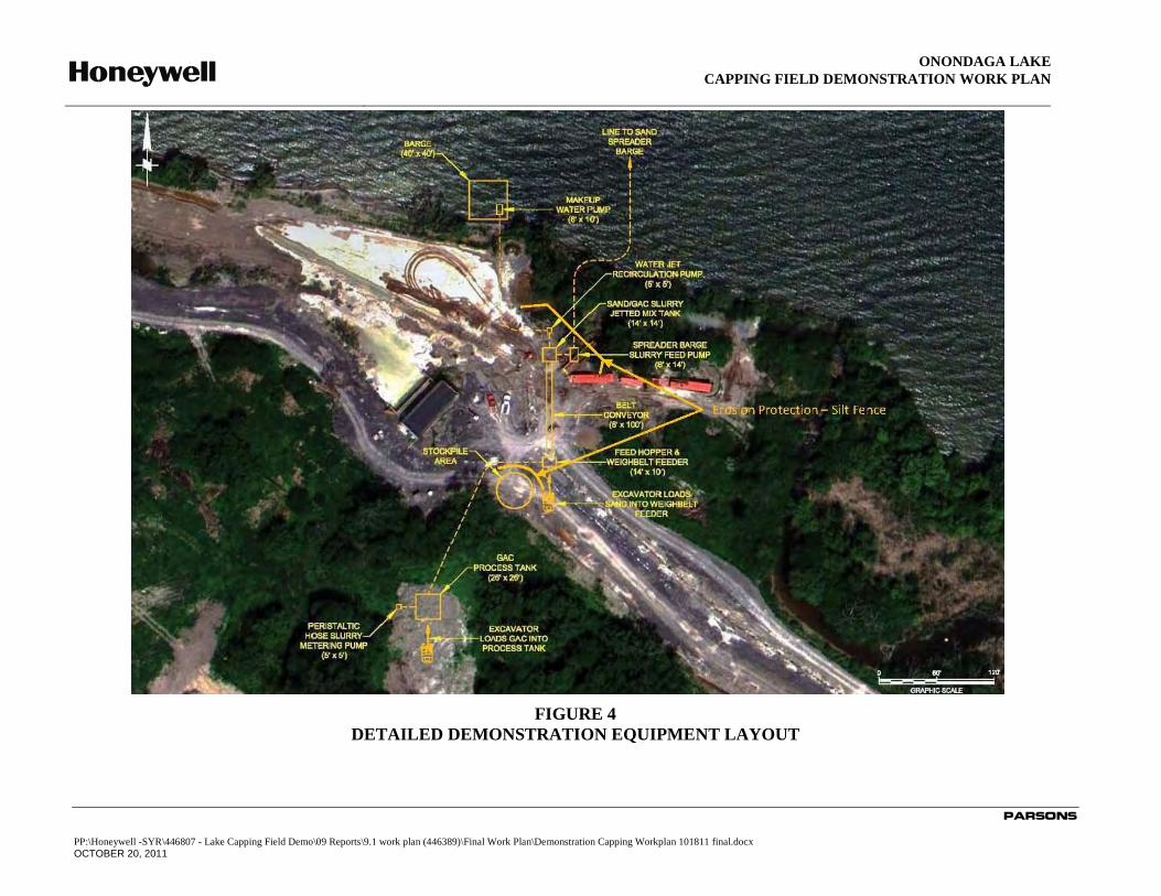
Measure (IRM) (Parsons 2010). Figure 4, Detailed Demonstration Equipment Layout, depicts the
location of erosion control measures to be implemented during the demonstration.

ONONDAGA LAKE
CAPPING FIELD DEMONSTRATION WORK PLAN
PARSONS
P:\Honeywell -SYR\446807 - Lake Capping Field Demo\09 Reports\9.1 work plan (446389)\Final Work Plan\Demonstration Capping Workplan 101811 final.docx
October 20, 2011
2-3
2.1.3 Road Upgrades
Upgrades to existing site roads, if required, may include placing and grading of gravel,
recycled asphalt, crushed rock, or other appropriate aggregate material on an as-needed basis.
Aggregate material will be obtained from off-site, or reused from on-site sources if available.
2.1.4 Site Clearing
Site clearing will be performed in designated work areas as required. Site clearing for the
work described in this Work Plan will take place near the area of Wastebed B/Harbor Brook as
shown on the shoreline support area Figure 1. Site clearing may include of cutting and removing
trees, if required. The area will be leveled as required and covered with gravel to make a
platform for the on-shore capping slurry equipment.
2.1.5 Support Area
Temporary facilities, sanitary facilities, storage containers, and material handling equipment
will be installed as required.
2.2 MATERIAL TRANSPORT
Cap demonstration material will be trucked to the site. Transport routes to the site will
maximize major highways as shown in Figure 2.
GAC will be delivered on site in prepackaged 1,000 pound supersacks. GAC will be kept
dry and stored in the supersacks until they are introduced into the GAC process tank for
saturation. Trucks delivering the GAC will take the same routes onto the site as the capping
material trucks above.
2.3 MATERIAL STAGING
Material stockpiles will be used to supply the necessary capping materials throughout the
cap demonstration project. Stockpiles will be kept to a minimum size, with an estimated one to
three days of quantity available to ensure the demonstration can be performed as scheduled
without delays. Maintaining small stockpiles will minimize the need to handle the capping
material multiple times, reduce the stockpile maintenance required, and result in as small a
footprint of the stockpile as practicable.
2.4 CAP MATERIAL MIXING AND DELIVERY SYSTEM CONSTRUCTION
A hydraulic capping system will be used for the placement of capping materials during this
demonstration. System components will be comprised of the same equipment planned for the
full-scale capping construction, or equipment similar in capacity and function to what will be
used at full-scale. A Process Flow diagram for the demonstration is shown on Figure 3. The
hydraulic slurry system will be comprised of an upland hopper that will feed capping materials
(sand and GAC mixed together) from a stockpile to a slurry system that will mix the capping
materials with water from the lake. The slurried cap materials will be pumped through a pipeline
by a booster pump to the spreader barge at the demonstration location. The hydraulic cap
placement system will consist of a spreader barge equipped with a diffuser plate that reduces the
ONONDAGA LAKE
CAPPING FIELD DEMONSTRATION WORK PLAN
PARSONS
P:\Honeywell -SYR\446807 - Lake Capping Field Demo\09 Reports\9.1 work plan (446389)\Final Work Plan\Demonstration Capping Workplan 101811 final.docx
October 20, 2011
2-4
energy and evenly distributes the capping materials. Each of these components is discussed
below.
2.4.1 Sand Feed System
The sand slurry system will consist of a stockpile, feed hopper, weighbelt feeder, and a belt
conveyor. A hydraulic excavator will load the sand material into the hopper. The sand will then
be dropped to a belt conveyor with a weigh-belt scale and transported to the sand/GAC slurry
mix tank at a constant rate. It is anticipated that the feed rate for the sand material during the
field demonstration will be approximately 100 CY per hour. The actual rate of application may
vary throughout the test.
2.4.2 Carbon (GAC) Feed System
The GAC will be mixed with water prior to placement in order to saturate the void space of
the GAC (i.e. removing entrained air) to promote more rapid settling through the water column
during placement. The GAC is planned to be loaded at the end of the day in order to soak
overnight. Although not expected, if dry GAC is required to be added to the agitated mix tank
during the test day, the minimum saturation time for the agitated GAC will be two hours. If
required, capping lanes that use GAC that has not been soaked overnight will be placed
separately from GAC that has soaked overnight. This will keep the variable of soaking consistent
within each demonstration test lane.
The GAC slurry system will consist of an agitated process mix tank, a water make-up pump,
and a slurry metering pump. GAC will be delivered and stored in 1,000 pound supersacks. A
hydraulic excavator will load the supersacks into the GAC process tank where it will be
combined with make-up water from the lake via a makeup water pump. The GAC will be mixed
with water to create a known concentration of GAC in the water solution. The agitation process
mix tank will homogenize the wetted GAC and maintain a uniform concentration. The GAC
slurry will then be pumped from the tank through a peristaltic metering pump and flow meter,
and delivered to the sand/GAC slurry mix tank at the desired rate, based on the planned GAC
dose in the chemical isolation layer. The rate of in situ GAC loading (in pounds of GAC per
hour, or per square foot) slurry will be determined from the proposed carbon dosage and the rate
of the sand being introduced into the sand/GAC slurry mix tank.
2.4.3 Sand/GAC Slurry Mix Tank
Sand and GAC will be introduced into the makeup water that is being pumped through the
slurry mix tank. The sand and GAC will be mixed into the water to form a slurry. The tank will
be fitted with water jet recirculation pumps to keep the slurry in suspension and homogenized.
The slurry will be drawn from the tank through a slurry feed pump and pumped out to the
spreader barge for placement.
2.4.4 Slurry Line
A HDPE pipeline will be used to transport the sand/GAC slurry to the spreader barge. The
HDPE pipe and fittings will be mobilized to the site and fused together to produce the required
length of pipe for the demonstration test. The slurry pipeline will be marked by buoys and lights
to warn recreational boats of the work area. The line may be submerged where appropriate.

ONONDAGA LAKE
CAPPING FIELD DEMONSTRATION WORK PLAN
PARSONS
P:\Honeywell -SYR\446807 - Lake Capping Field Demo\09 Reports\9.1 work plan (446389)\Final Work Plan\Demonstration Capping Workplan 101811 final.docx
October 20, 2011
2-5
2.4.5 Spreader Barge
The HDPE slurry pipe will be connecected to a diffuser located on the spreader barge. The
diffuser system will be attached to the back of the barge. The barge will have a waterfall type
discharge apparatus (steel plate angled towards the water) positioned on the deck of the barge.
The angled discharge plate will act to dissipate the energy in the capping material slurry
delivered to the placement barge via the floating line, allowing the slurry to enter the water in a
controlled manner, thus allowing for uniform placement of capping materials. The diffuser barge
will have a hydraulic cable winch system and anchors to facilitate the movement of the barge for
placement of the material. Using the arrangement of winches and anchors, the diffuser barge will
be operated in a series of parallel “lanes” equal to the width of the diffuser barge itself.
2.4.6 Demarcation System
A demarcation system will be installed around the demonstration area to delineate the
demonstration area. The demarcation of the demonstration area will include lighted buoys for
visibility of the area at night, in accordance with US Coast Guard regulations. The demarcation
system will be held in place with Danforth type anchors, chain, and anchor line. Spacing of the
anchors will allow minimal movement in the current and wind and accommodate any water level
fluctuations. Components will be installed and anchored prior to the start of the demonstration
test.

ONONDAGA LAKE
CAPPING FIELD DEMONSTRATION WORK PLAN
PARSONS
P:\Honeywell -SYR\446807 - Lake Capping Field Demo\09 Reports\9.1 work plan (446389)\Final Work Plan\Demonstration Capping Workplan 101811 final.docx
October 20, 2011
2-6
2.5 CAP PLACEMENT FIELD DEMONSTRATION
2.5.1 Demonstration Procedures
The capping materials will be placed in a series of parallel “lanes” that are 20 ft. wide
(corresponding to the width of the angle plate diffuser on the spreader barge). The cap placement
operation will start at one end of a capping lane, and the sand spreader barge will progress along
that lane at a constant rate that will provide the target lift thickness for the capping material.
Multiple lifts in the same capping lane may be required to achieve the targeted thickness, with
lifts varying between 6 inches and 12 inches. This is the same lift thickness anticipated during
full-scale capping operations in 2012.
Placement within a given capping lane may progress from shallow to deep water, or from
deep to shallow water, depending on a number of factors including the anchor configurations,
water depth, lift thickness, spreader barge location, etc. A capping lane may encompass the
complete demonstration water depth (5 ft. of water to 30 ft. of water), or just a targeted portion
of depth (i.e., 5-10 ft. of water, or 15-20 ft. of water).

ONONDAGA LAKE
CAPPING FIELD DEMONSTRATION WORK PLAN
PARSONS
P:\Honeywell -SYR\446807 - Lake Capping Field Demo\09 Reports\9.1 work plan (446389)\Final Work Plan\Demonstration Capping Workplan 101811 final.docx
October 20, 2011
2-7
The demonstration cap will be constructed with two target GAC placement rates. For visual
observation of the vertical distribution of GAC, a placement rate of 1.0 pound per square foot
will be employed in each targeted water depth. During the column testing, this dosage rate
allowed for visual observation of the carbon in the sand layer. Due to the volume of carbon used
for the 1.0 pound per square foot dosage, this rate will applied as few times as necessary. The
second GAC placement rate of 0.25 pounds per square foot will be used for lower dose testing.
This lower rate is the approximate average dosage rate proposed for the amended cap being
placed in 2012.
It is anticipated that approximately one to three targeted depth capping lanes will be placed
per day. The total duration for the demonstration is anticiapted to be approximately one to two
weeks, subject to actual production rates, weather delays, etc. Samples collected at various steps
within the mixing and delivery process, as well as from the placed cap material, will be analyzed
for GAC content, as discussed in Section 2.5.2. Analysis will be conducted with a fast turn-
around-time (e.g., overnight) so that results from one day will be available to guide the next
day’s activities.
It is expected that the testing will establish a correlation between the measured input
concentration of GAC and the measured in-place concentration. Once this correlation is
established, refinements can be made to the placement technique, sampling method, carbon input
volume and/or carbon verification procedures to fine tune the system. This flexibility of
placement, sampling, and testing variables will allow a dynamic field demonstration. This will
allow the most flexibility to ensure that the carbon can be consistently placed in the sand cap
during full scale operations.
2.5.2 Verification Sampling and Analysis
Post-placement verification samples will be collected as part of the capping demonstration
project to measure the thickness of capping materials placed and the concentration of GAC.
Verification samples will be collected using a “catch pan”, which consists of a small open-top
container placed on the bottom piror to cap placement and collected after placement to measure
the applied thickness. Multiple catch pans will be deployed for each capping lane demonstration
lift. The targeted water depth will vary with each capping lane demonstration lift. The catch pans
will rest on the existing sediment surface and will be attached to a rope and buoy to allow for
retrieval. The capping operations will pass over the top of a catch pan during each capping lift.
After a lift with the capping spreader barge, the catch pans will be retrieved. The thickness of
capping material will be measured in each catch pan and samples will be collected for
measurement of the GAC content and comparison to the input GAC content.
Verification samples will also be collected at several steps during the cap material mixing
and delivery process (i.e., prior to placement on the lake bottom) to measure the GAC content.
Samples will be collected from the discharge of the carbon mix tank, the discharge of the
sand/GAC slurry mix tank, and just prior to entering the water column, as shown in Figure 3.
Samples will be collected through sampling ports installed at the exit of the carbon slurry mix
tank, the sand/GAC slurry mix tank, and at the discharge of the spreader barge. A process
sampling summary is provided below.
ONONDAGA LAKE
CAPPING FIELD DEMONSTRATION WORK PLAN
PARSONS
P:\Honeywell -SYR\446807 - Lake Capping Field Demo\09 Reports\9.1 work plan (446389)\Final Work Plan\Demonstration Capping Workplan 101811 final.docx
October 20, 2011
2-8
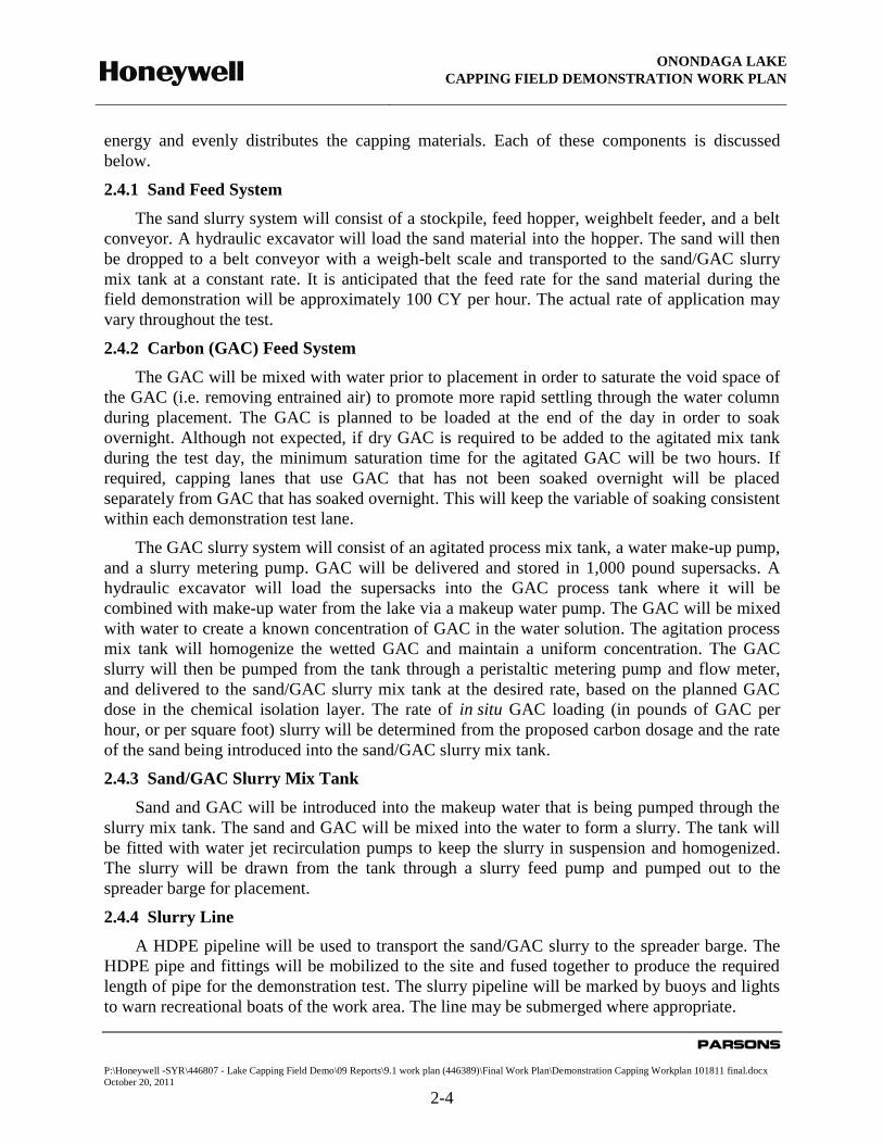
Sample
Location
Primary
Catch pans
Secondary
GAC Process
Tank
Secondary
Sand/GAC
Slurry Mix
Tank
Secondary
Energy Diffuser
Plate
Sample
Frequency¹ Min. 3 per run² 10 minute intervals
10 minute
intervals
10 minute
intervals
Analysis Thickness, GAC
dosage
GAC/water slurry
concentration GAC dosage GAC dosage
¹ Test sample frequency may be varied depending on the target water depth and length of a capping lane.
² A run consists of a single capping lane, through a targeted water depth. The targeted water depth will
vary for each run, and may consist of a similar depth interval (i.e. 10 ft to 15 ft, or 20 ft to 25 ft), or a
larger water depth interval (i.e. 5 ft to 25 ft).
Once the sample has been collected, it will be transferred to shore for measurement of GAC
content. GAC will be removed from the sample matrix by thermal destruction and quantified.
The thermal destruction method will be used to accurately measure, by weight, the amount of
GAC present in sand/GAC slurry samples. The method was developed to allow for large sample
sizes and rapid turnaround times.
The thermal method developed for the GAC removal relies on exposing the sample to heat
that will burn off the GAC without burning off the sand. Full capping catch pan samples taken
from a capping run will be placed in containers for analysis at the lab. The samples will be
sieved to remove particle sizes larger and smaller than the expected GAC particles. This sieve
step reduces the sample size to be dried and heated. Following the sieve step, the samples will be
placed in an oven and heated to 110°C to remove the water from the sample. Once the water has
been removed the sample will be weighted and placed in an oven and heated to approximately
500°C to burn off the GAC. The sample will be reweighed to determine the quantity of GAC in
the sample. The weight of GAC removed from the sample will be used with the area of the catch
pan to determine the dose of the GAC in the layer (lb/sf).Each day's operations will include a
control sample of a known weight of carbon in a sand matrix to verify recovery of GAC within
the matrix. If more than 20 samples are taken per day, a control sample will be taken for each 20
field demonstration samples.
Demonstration samples will be used to track the GAC content in the capping material
throughout the process, from initial mixing with sand through the delivery to the water column,
and for comparison with GAC content of the capping materials measured in situ following
placement (via catch pans discussed above). It is anticipated that for full-scale capping, a
relationship will established between the input GAC content to the in situ (post-placement) GAC
content, and the frequency of in situ sampling can be reduced or eliminated.
2.5.3 Water Quality Sampling
During the Capping Field Demonstration, turbidity will be monitored at performance and
compliance monitoring stations to assess the water quality conditions during capping at locations

ONONDAGA LAKE
CAPPING FIELD DEMONSTRATION WORK PLAN
PARSONS
P:\Honeywell -SYR\446807 - Lake Capping Field Demo\09 Reports\9.1 work plan (446389)\Final Work Plan\Demonstration Capping Workplan 101811 final.docx
October 20, 2011
2-9
similar to the full-scale program. Performance monitoring stations will be placed approximately
300 ft. outside of the demarcation curtain at upcurrent (background), down current, and adjacent
to the demonstration area. A compliance monitoring station will be placed approximately 500 ft.
outside of the demarcation curtain. Results will be continuously recorded (i.e., 15-minute interval
averaged into 2-hour values) from each location during the demonstration. Water quality
sampling locations are depicted in Figure 5.
Visual monitoring of turbidity during the demonstration will also be employed. If visual
observations indicate that revisions to the monitoring program, such as adding monitoring
locations or moving the performance monitoring locations closer to the work area would provide
more useful data, the Design Team will consult with DEC on the new proposed location (s).
Washed sand will be used for the demonstration test to minimize turbidity and focus the
demonstration on the placement of GAC in the sand layer. Un-washed screened sand may be
used after the initial demonstration to provide observational and turbidity data for use in the Lake
Final Design Documents.
2.5.4 Current Velocity and Wave Height Measurement
During the Capping Field Demonstration, current velocity will be measured to assess the
water current conditions during capping demonstration. The current velocity will be measured at
a specified point within the water column for the demonstration. The water velocities will be
measured in 20 ft. of water at the middle of the water column. The monitor will take real time
velocity throughout the demonstration. The monitor will be located approximately 200 ft. west of
the demonstration area.
Wave heights will be measured and recorded throughout the demonstration placement in
order to evaluate potential wave affects on placement.
2.6 REPORTING
After completion of the demonstration test, a Capping Field Demonstration Final Report will
be drafted and submitted to NYSDEC to compile the information collected during the
demonstration. The report will include the equipment utilized for the test, and the details and
results of the sand and GAC placement. The results of the demonstration will be communicated
to the NYSDEC by early December 2011 for benefit of review and consideration prior to
submittal of the Onondaga Lake Capping, Dredging, Habitat and Profundal Zone Final Design.

ONONDAGA LAKE
CAPPING FIELD DEMONSTRATION WORK PLAN
PARSONS
P:\Honeywell -SYR\446807 - Lake Capping Field Demo\09 Reports\9.1 work plan (446389)\Final Work Plan\Demonstration Capping Workplan 101811 final.docx
October 20, 2011
3-1
SECTION 3
HEALTH AND SAFETY
3.1 HEALTH AND SAFETY OVERVIEW
The health and safety of the site-workers are of paramount importance in designing and
implementing the lake remedy. Worker safety is addressed through a system of planning and
management that will be performed by Parsons during the construction planning and execution
stages. A Project Safety Plan (PSP) (Parsons, 2011) has been developed to document the worker
safety system.
As stated in Section 1.1, the Capping Field Demonstration work will be performed prior to
the start of dredging and will consist of conventional hydraulic capping equipment with clean
materials delivered to the site. The field demonstration work will involve placement of clean
sand on top of the lake sediments. With this consideration, risks to the health and safety of the
community during field demonstration work are very low.
3.2 COMMUNITY HEALTH AND SAFETY
Community project health and safety procedures have been developed to provide safety
during the capping field demonstration. These initiatives will provide protection to both
Honeywell’s contractors and the local community. Initiatives include measures for site security
at the established work areas, traffic protection for both public vehicles and recreational vessels,
demarcation and navigational safety of the work area, preventive measures and responses for
addressing potential spills of petroleum, oils and lubricants, and Honeywell’s routine monitoring
of noise levels during operations.
3.2.1 Site Security
The land based work area has been established to support the project. Access to the site and
to this area will be restricted. Anyone wishing to access the site will be required to sign in and
show proper identification.
Security measures will include clearly identifying work areas (using flagging tape,
construction fencing, etc.) and restricting access where work is taking place. If any equipment is
to be left unattended overnight, additional security measures will be implemented, as necessary.
Precautions will be observed in order to protect materials, equipment, and completed work from
unauthorized public access, damage by theft, vandalism, and/or sabotage.
Each day, portable equipment will be secured in designated areas. If required, heavy
equipment will be relocated to a safe location and work areas will be properly barricaded.
Temporary fencing will be installed as required. On the lake, barges and support boats will be
securely anchored and all will have night lights, reflectors, and signage as appropriate.

ONONDAGA LAKE
CAPPING FIELD DEMONSTRATION WORK PLAN
PARSONS
P:\Honeywell -SYR\446807 - Lake Capping Field Demo\09 Reports\9.1 work plan (446389)\Final Work Plan\Demonstration Capping Workplan 101811 final.docx
October 20, 2011
3-2
3.3.2 In-Lake Activities and Lakeshore Support Area
A shoreline support area will be constructed on Honeywell lakeshore property. Shoreline
support areas for the capping activities will consist of, at a minimum, docks for access to the
lake, equipment staging for shoreline activities, cap material stockpiles, staging and storage of
other materials, equipment, and storage trailers.
In-lake work zones will be clearly marked. Buoys will be installed around the work
activities to alert the boating public to avoid work zones. Air horns or other appropriate means
will warn non-project vessels approaching an active work area to keep away. In addition, high
visibility demarcation booms will serve as a barrier to keep the boating public out of the work
area.
On-water equipment will use biodegradable hydraulic oils and antifreeze. The capping barge
will be equipped with safety equipment and spill prevention materials to address any petroleum
spills that may occur. Support vessels will also be equipped with safety equipment. Additional
spill prevention materials will be on hand at the lakeshore.
Water based equipment will be stored securely when not in use. Prior to disembarking a
project vessel for a shutdown period, workers will ensure vessel enclosures have been locked,
and equipment and supplies have been secured. When not in use, vessels will dock at or near the
project docking facilities, which will be illuminated during night hours.
2.3.3 Traffic Management
The traffic management strategy establishes preferred approved New York State Department
of Transportation (NYSDOT) roadways for trucks use in order to minimize congestion and
maximize safety. However, for specific times or activities, the routes may vary. Traffic to and
from the project sites will be active for the duration of the project including regular material
deliveries to the Capping Field Demonstration shore support area.
Traffic leaving the project work sites will be monitored for dirt/mud to minimize tracking
material onto the roads. Enforcement of project safe driving practices for drivers delivering
equipment and materials to the project sites will be covered with all employees. This includes
practices such as adhering to local speed limits and always covering loads with tarps. Awareness
training will be provided to contractors involved with the transport of demonstration materials.
To the extent practicable, traffic routes will maximize use of major state highways. The
route that will be used for traffic to and from the shoreline support area will be the same as was
used during the installation of the sheet pile barrier wall along the shoreline of the southwest
corner of the lake. Regular traffic to and from this location will include delivery of capping
materials and regular maintenance and site workers.
As depicted in Figure 2, incoming traffic will access this site from the Exit 7 ramp from
I-690 west bound. Outgoing traffic will access I-690 from State Fair Blvd. Based on normal
traffic in this area from the New York State Fair and nearby businesses, traffic associated with
the Capping Field Demonstration is expected to have minimal impact on the surrounding
community.
ONONDAGA LAKE
CAPPING FIELD DEMONSTRATION WORK PLAN
PARSONS
PP:\Honeywell -SYR\446807 - Lake Capping Field Demo\09 Reports\9.1 work plan (446389)\Final Work Plan\Demonstration Capping Workplan 101811 final.docx
OCTOBER 20, 2011
4-1
SECTION 4
REFERENCES
New York State Department of Environmental Conservation (NYSDEC) and United States
Environmental Protection Agency (USEPA) Region 2. 2005. Record of Decision. Onondaga
Lake Bottom Subsite of the Onondaga Lake Superfund Site. July 2005.
New York State Department of Health (NYSDOH). 2000. Generic Community Air Monitoring
Plan.
Parsons 2011. Draft Onondaga Lake Capping, Dredging, and Habitat Intermediate Design,
January 2011.

ONONDAGA LAKE
CAPPING FIELD DEMONSTRATION WORK PLAN
PARSONS
PP:\Honeywell -SYR\446807 - Lake Capping Field Demo\09 Reports\9.1 work plan (446389)\Final Work Plan\Demonstration Capping Workplan 101811 final.docx
OCTOBER 20, 2011
FIGURES

ONONDAGA LAKE
CAPPING FIELD DEMONSTRATION WORK PLAN
PARSONS
PP:\Honeywell -SYR\446807 - Lake Capping Field Demo\09 Reports\9.1 work plan (446389)\Final Work Plan\Demonstration Capping Workplan 101811 final.docx
OCTOBER 20, 2011
FIGURE 1
FIGURE 1
CAP DEMONSTRATION

ONONDAGA LAKE
CAPPING FIELD DEMONSTRATION WORK PLAN
PARSONS
PP:\Honeywell -SYR\446807 - Lake Capping Field Demo\09 Reports\9.1 work plan (446389)\Final Work Plan\Demonstration Capping Workplan 101811 final.docx
OCTOBER 20, 2011
FIGURE 2
DEMONSTRATION MATERIAL TRANSPORTATION ROUTES

ONONDAGA LAKE
CAPPING FIELD DEMONSTRATION WORK PLAN
PARSONS
PP:\Honeywell -SYR\446807 - Lake Capping Field Demo\09 Reports\9.1 work plan (446389)\Final Work Plan\Demonstration Capping Workplan 101811 final.docx
OCTOBER 20, 2011
FIGURE 3
PROCESS FLOW DIAGRAM
ONONDAGA LAKE
CAPPING FIELD DEMONSTRATION WORK PLAN
PARSONS
PP:\Honeywell -SYR\446807 - Lake Capping Field Demo\09 Reports\9.1 work plan (446389)\Final Work Plan\Demonstration Capping Workplan 101811 final.docx
OCTOBER 20, 2011
FIGURE 4
DETAILED DEMONSTRATION EQUIPMENT LAYOUT

ONONDAGA LAKE
CAPPING FIELD DEMONSTRATION WORK PLAN
PARSONS
PP:\Honeywell -SYR\446807 - Lake Capping Field Demo\09 Reports\9.1 work plan (446389)\Final Work Plan\Demonstration Capping Workplan 101811 final.docx
OCTOBER 20, 2011
FIGURE 5
WATER QUALITY MONITORING LOCATIONS