T60 REGULATOR REPAIR KIT INSTRUCTIONS - … · 3030 S Susan Street PPI-68 REV. B IMPCO Technologies...
15
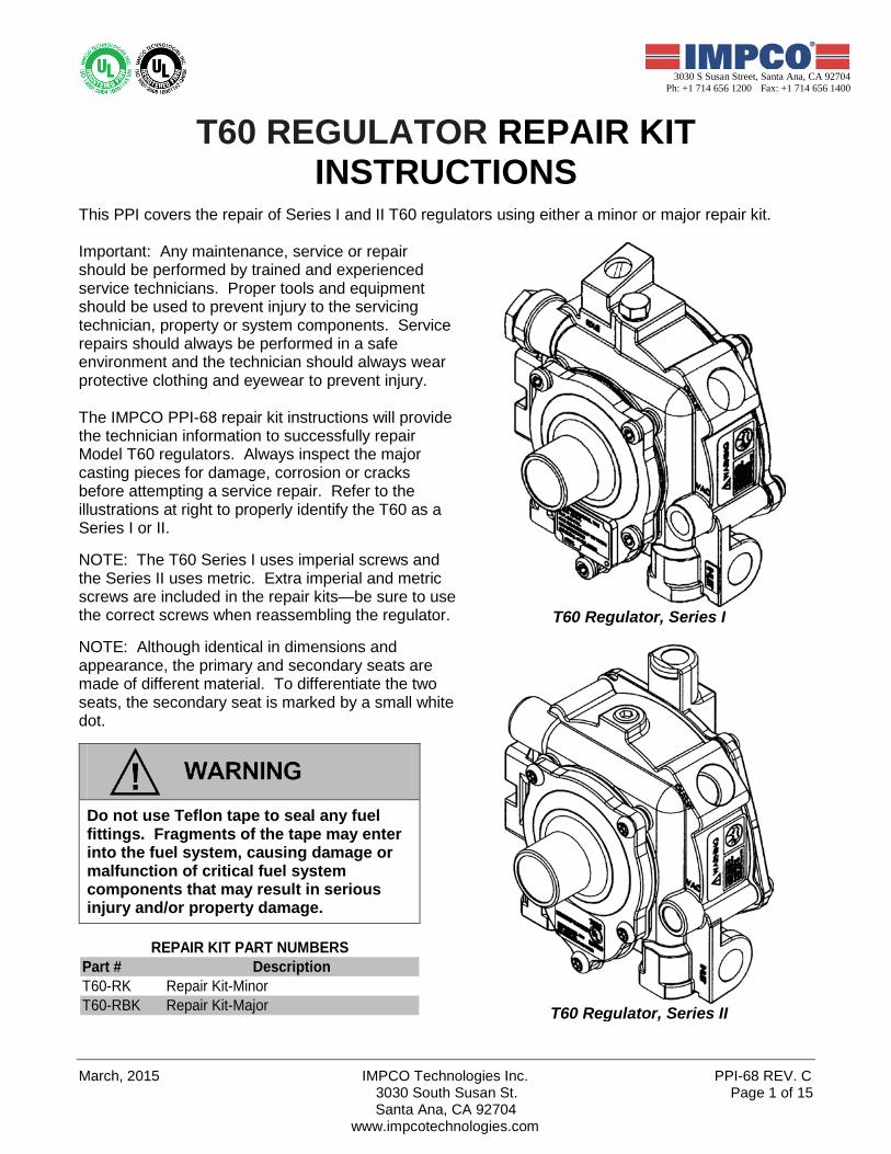
March, 2015 IMPCO Technologies Inc. PPI-68 REV. C 3030 South Susan St. Page 1 of 15 Santa Ana, CA 92704 www.impcotechnologies.com 3030 S Susan Street, Santa Ana, CA 92704 Ph: +1 714 656 1200 Fax: +1 714 656 1400 T60 REGULATOR REPAIR KIT INSTRUCTIONS This PPI covers the repair of Series I and II T60 regulators using either a minor or major repair kit. Important: Any maintenance, service or repair should be performed by trained and experienced service technicians. Proper tools and equipment should be used to prevent injury to the servicing technician, property or system components. Service repairs should always be performed in a safe environment and the technician should always wear protective clothing and eyewear to prevent injury. The IMPCO PPI-68 repair kit instructions will provide the technician information to successfully repair Model T60 regulators. Always inspect the major casting pieces for damage, corrosion or cracks before attempting a service repair. Refer to the illustrations at right to properly identify the T60 as a Series I or II. NOTE: The T60 Series I uses imperial screws and the Series II uses metric. Extra imperial and metric screws are included in the repair kits—be sure to use the correct screws when reassembling the regulator. NOTE: Although identical in dimensions and appearance, the primary and secondary seats are made of different material. To differentiate the two seats, the secondary seat is marked by a small white dot. Do not use Teflon tape to seal any fuel fittings. Fragments of the tape may enter into the fuel system, causing damage or malfunction of critical fuel system components that may result in serious injury and/or property damage. Part # Description T60-RK Repair Kit-Minor T60-RBK Repair Kit-Major REPAIR KIT PART NUMBERS T60 Regulator, Series I T60 Regulator, Series II
Transcript of T60 REGULATOR REPAIR KIT INSTRUCTIONS - … · 3030 S Susan Street PPI-68 REV. B IMPCO Technologies...
March, 2015 IMPCO Technologies Inc. PPI-68 REV. C 3030 South Susan St. Page 1 of 15
Santa Ana, CA 92704 www.impcotechnologies.com
3030 S Susan Street, Santa Ana, CA 92704 Ph: +1 714 656 1200 Fax: +1 714 656 1400
T60 REGULATOR REPAIR KIT INSTRUCTIONS
This PPI covers the repair of Series I and II T60 regulators using either a minor or major repair kit. Important: Any maintenance, service or repair should be performed by trained and experienced service technicians. Proper tools and equipment should be used to prevent injury to the servicing technician, property or system components. Service repairs should always be performed in a safe environment and the technician should always wear protective clothing and eyewear to prevent injury. The IMPCO PPI-68 repair kit instructions will provide the technician information to successfully repair Model T60 regulators. Always inspect the major casting pieces for damage, corrosion or cracks before attempting a service repair. Refer to the illustrations at right to properly identify the T60 as a Series I or II. NOTE: The T60 Series I uses imperial screws and the Series II uses metric. Extra imperial and metric screws are included in the repair kits—be sure to use the correct screws when reassembling the regulator. NOTE: Although identical in dimensions and appearance, the primary and secondary seats are made of different material. To differentiate the two seats, the secondary seat is marked by a small white dot.
Do not use Teflon tape to seal any fuel fittings. Fragments of the tape may enter into the fuel system, causing damage or malfunction of critical fuel system components that may result in serious injury and/or property damage.
Part # DescriptionT60-RK Repair Kit-MinorT60-RBK Repair Kit-Major
REPAIR KIT PART NUMBERS
T60 Regulator, Series I
T60 Regulator, Series II
PPI-68 REV. B IMPCO Technologies Inc. May, 2014 3030 South Susan St. Page 2 of 15
Santa Ana, CA 92704 www.impcotechnologies.com
3030 S Susan Street, Santa Ana, CA 92704 Ph: +1 714 656 1200 Fax: +1 714 656 1400
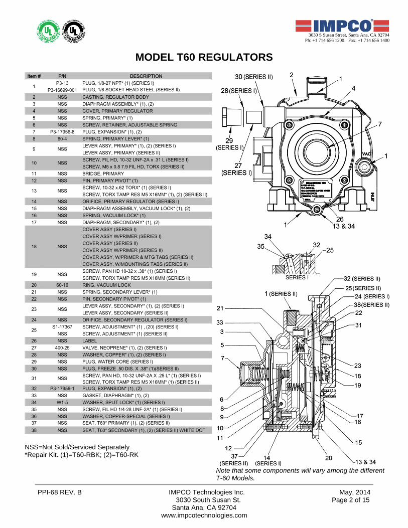
MODEL T60 REGULATORS
Item # P/N DESCRIPTION P3-13 PLUG, 1/8-27 NPT* (1) (SERIES I)
P3-16699-001 PLUG, 1/8 SOCKET HEAD STEEL (SERIES II)2 NSS CASTING, REGULATOR BODY 3 NSS DIAPHRAGM ASSEMBLY* (1), (2)4 NSS COVER, PRIMARY REGULATOR5 NSS SPRING, PRIMARY* (1)6 NSS SCREW, RETAINER, ADJUSTABLE SPRING7 P3-17956-8 PLUG, EXPANSION* (1), (2)8 60-4 SPRING, PRIMARY LEVER* (1)
LEVER ASSY, PRIMARY* (1), (2) (SERIES I)LEVER ASSY, PRIMARY (SERIES II)SCREW, FIL HD, 10-32 UNF-2A x .31 L (SERIES I)SCREW, M5 x 0.8 7.9 FIL HD, TORX (SERIES II)
11 NSS BRIDGE, PRIMARY12 NSS PIN, PRIMARY PIVOT* (1)
SCREW, 10-32 x.62 TORX* (1) (SERIES I)SCREW, TORX TAMP RES M5 X16MM* (1), (2) (SERIES II)
14 NSS ORIFICE, PRIMARY REGULATOR (SERIES I)15 NSS DIAPHRAGM ASSEMBLY, VACUUM LOCK* (1), (2)16 NSS SPRING, VACUUM LOCK* (1)17 NSS DIAPHRAGM, SECONDARY* (1), (2)
COVER ASSY (SERIES I)COVER ASSY W/PRIMER (SERIES I)COVER ASSY (SERIES II)COVER ASSY W/PRIMER (SERIES II)COVER ASSY, W/PRIMER & MTG TABS (SERIES II)COVER ASSY, W/MOUNTINGS TABS (SERIES II)SCREW, PAN HD 10-32 x .38* (1) (SERIES I)SCREW, TORX TAMP RES M5 X16MM (SERIES II)
20 60-16 RING, VACUUM LOCK 21 NSS SPRING, SECONDARY LEVER* (1)22 NSS PIN, SECONDARY PIVOT* (1)
LEVER ASSY, SECONDARY* (1), (2) (SERIES I)LEVER ASSY, SECONDARY (SERIES II)
24 NSS ORIFICE, SECONDARY REGULATOR (SERIES I)S1-17367 SCREW, ADJUSTMENT* (1) , (20) (SERIES I)
NSS SCREW, ADJUSTMENT* (1) (SERIES II)26 NSS LABEL27 400-25 VALVE, NEOPRENE* (1), (2) (SERIES I)28 NSS WASHER, COPPER* (1), (2) (SERIES I)29 NSS PLUG, WATER CORE (SERIES I)30 NSS PLUG, FREEZE .50 DIS. X .38* (1)(SERIES II)
SCREW, PAN HD, 10-32 UNF-2A X .25 L* (1) (SERIES I)SCREW, TORX TAMP RES M5 X16MM* (1) (SERIES II)
32 P3-17956-1 PLUG, EXPANSION* (1), (2)33 NSS GASKET, DIAPHRAGM* (1), (2)34 W1-5 WASHER, SPLIT LOCK* (1) (SERIES I)35 NSS SCREW, FIL HD 1/4-28 UNF-2A* (1) (SERIES I)36 NSS WASHER, COPPER-SPECIAL (SERIES I)37 NSS SEAT, T60* PRIMARY (1), (2) (SERIES II)38 NSS SEAT, T60* SECONDARY (1), (2) (SERIES II) WHITE DOT
1
NSS
10 NSS
13
NSS9
NSS
31 NSS
NSS
NSS19
25
23
18
NSS=Not Sold/Serviced Separately *Repair Kit. (1)=T60-RBK; (2)=T60-RK
Note that some components will vary among the different T-60 Models.
March, 2015 IMPCO Technologies Inc. PPI-68 REV. C 3030 South Susan St. Page 3 of 15
Santa Ana, CA 92704 www.impcotechnologies.com
3030 S Susan Street, Santa Ana, CA 92704 Ph: +1 714 656 1200 Fax: +1 714 656 1400
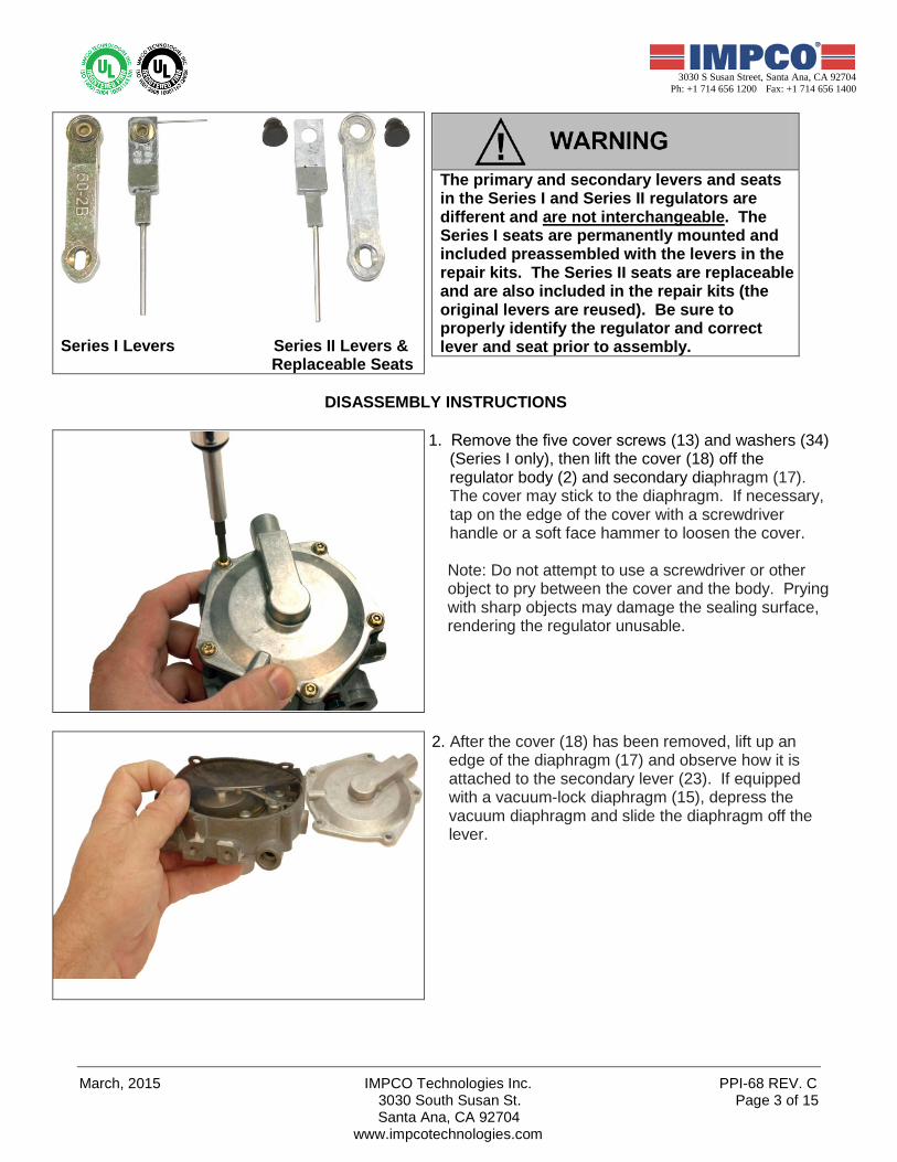
Series I Levers Series II Levers & Replaceable Seats
The primary and secondary levers and seats in the Series I and Series II regulators are different and are not interchangeable. The Series I seats are permanently mounted and included preassembled with the levers in the repair kits. The Series II seats are replaceable and are also included in the repair kits (the original levers are reused). Be sure to properly identify the regulator and correct lever and seat prior to assembly.
DISASSEMBLY INSTRUCTIONS
1. Remove the five cover screws (13) and washers (34) (Series I only), then lift the cover (18) off the regulator body (2) and secondary diaphragm (17). The cover may stick to the diaphragm. If necessary, tap on the edge of the cover with a screwdriver handle or a soft face hammer to loosen the cover.
Note: Do not attempt to use a screwdriver or other object to pry between the cover and the body. Prying with sharp objects may damage the sealing surface, rendering the regulator unusable.
2. After the cover (18) has been removed, lift up an edge of the diaphragm (17) and observe how it is attached to the secondary lever (23). If equipped with a vacuum-lock diaphragm (15), depress the vacuum diaphragm and slide the diaphragm off the lever.

PPI-68 REV. B IMPCO Technologies Inc. May, 2014 3030 South Susan St. Page 4 of 15
Santa Ana, CA 92704 www.impcotechnologies.com
3030 S Susan Street, Santa Ana, CA 92704 Ph: +1 714 656 1200 Fax: +1 714 656 1400
3. Loosen the two screws (31) holding the secondary lever pivot pin (22) in place and remove pin, lever (23) and spring (21).
Vacuum Lock Models Only (Skip to Step 5 for models without a Vacuum Lock): 4. Remove the four screws (19) holding the vacuum-
lock ring (20) and diaphragm (15) in place. Lift ring, diaphragm and spring (16) from regulator body (2).
5. Remove the expansion plug (7) by drilling a small hole in the plug, carefully threading in a small sheet metal screw, then pulling the plug out using a slide hammer (as shown in the photo of Step 11). Once the plug is removed, also remove the primary pressure adjusting screw (6) and spring (5).
Use care when drilling the expansion plug hole by not drilling further into the retaining screw.
March, 2015 IMPCO Technologies Inc. PPI-68 REV. C 3030 South Susan St. Page 5 of 15
Santa Ana, CA 92704 www.impcotechnologies.com
3030 S Susan Street, Santa Ana, CA 92704 Ph: +1 714 656 1200 Fax: +1 714 656 1400
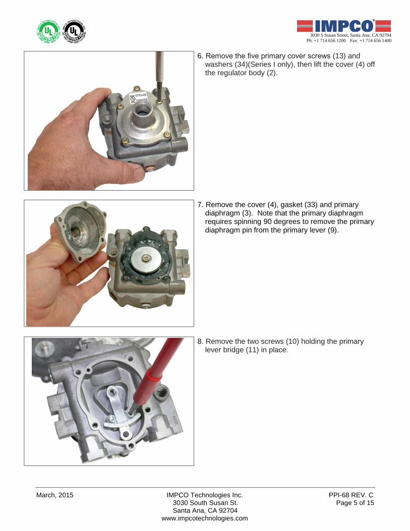
6. Remove the five primary cover screws (13) and washers (34)(Series I only), then lift the cover (4) off the regulator body (2).
7. Remove the cover (4), gasket (33) and primary diaphragm (3). Note that the primary diaphragm requires spinning 90 degrees to remove the primary diaphragm pin from the primary lever (9).
8. Remove the two screws (10) holding the primary lever bridge (11) in place.
PPI-68 REV. B IMPCO Technologies Inc. May, 2014 3030 South Susan St. Page 6 of 15
Santa Ana, CA 92704 www.impcotechnologies.com
3030 S Susan Street, Santa Ana, CA 92704 Ph: +1 714 656 1200 Fax: +1 714 656 1400
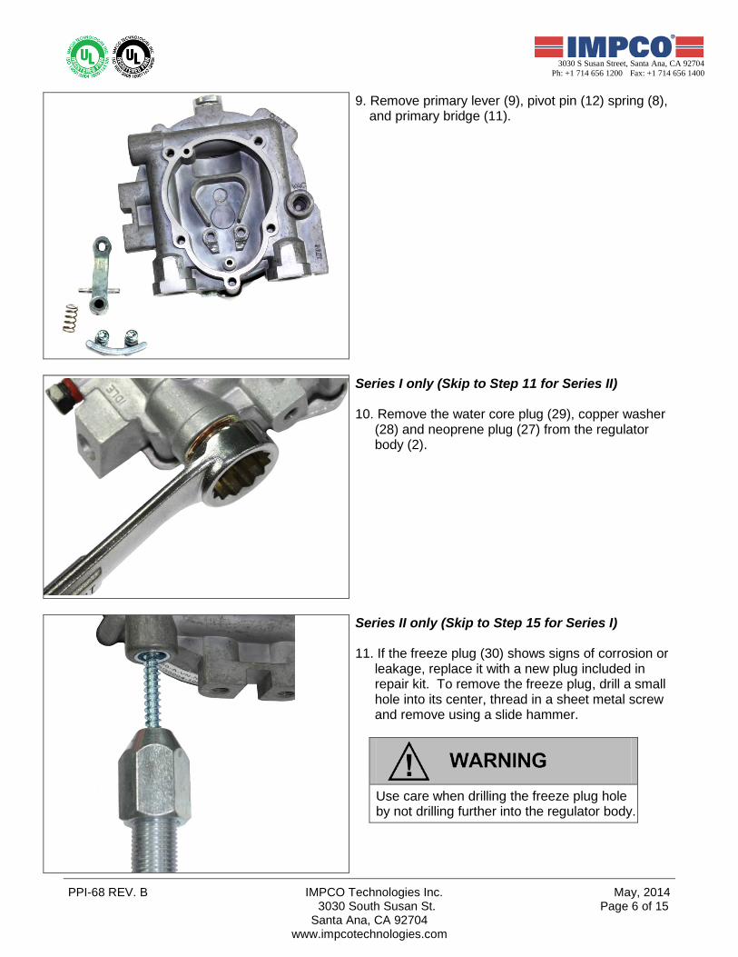
9. Remove primary lever (9), pivot pin (12) spring (8), and primary bridge (11).
Series I only (Skip to Step 11 for Series II) 10. Remove the water core plug (29), copper washer
(28) and neoprene plug (27) from the regulator body (2).
Series II only (Skip to Step 15 for Series I) 11. If the freeze plug (30) shows signs of corrosion or
leakage, replace it with a new plug included in repair kit. To remove the freeze plug, drill a small hole into its center, thread in a sheet metal screw and remove using a slide hammer.
Use care when drilling the freeze plug hole by not drilling further into the regulator body.
March, 2015 IMPCO Technologies Inc. PPI-68 REV. C 3030 South Susan St. Page 7 of 15
Santa Ana, CA 92704 www.impcotechnologies.com
3030 S Susan Street, Santa Ana, CA 92704 Ph: +1 714 656 1200 Fax: +1 714 656 1400
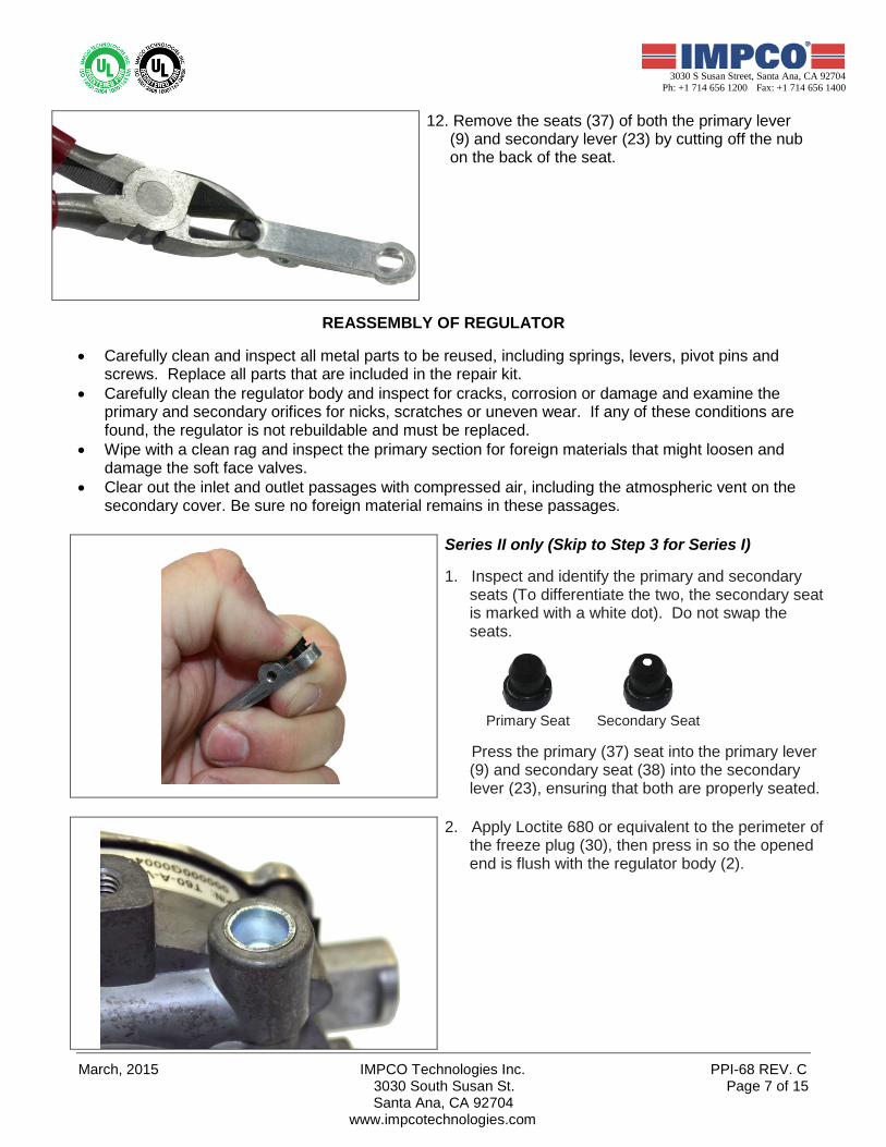
12. Remove the seats (37) of both the primary lever (9) and secondary lever (23) by cutting off the nub on the back of the seat.
REASSEMBLY OF REGULATOR
• Carefully clean and inspect all metal parts to be reused, including springs, levers, pivot pins and
screws. Replace all parts that are included in the repair kit. • Carefully clean the regulator body and inspect for cracks, corrosion or damage and examine the
primary and secondary orifices for nicks, scratches or uneven wear. If any of these conditions are found, the regulator is not rebuildable and must be replaced.
• Wipe with a clean rag and inspect the primary section for foreign materials that might loosen and damage the soft face valves.
• Clear out the inlet and outlet passages with compressed air, including the atmospheric vent on the secondary cover. Be sure no foreign material remains in these passages.
Series II only (Skip to Step 3 for Series I) 1. Inspect and identify the primary and secondary
seats (To differentiate the two, the secondary seat is marked with a white dot). Do not swap the seats.
Primary Seat Secondary Seat
Press the primary (37) seat into the primary lever
(9) and secondary seat (38) into the secondary lever (23), ensuring that both are properly seated.
2. Apply Loctite 680 or equivalent to the perimeter of the freeze plug (30), then press in so the opened end is flush with the regulator body (2).
PPI-68 REV. B IMPCO Technologies Inc. May, 2014 3030 South Susan St. Page 8 of 15
Santa Ana, CA 92704 www.impcotechnologies.com
3030 S Susan Street, Santa Ana, CA 92704 Ph: +1 714 656 1200 Fax: +1 714 656 1400
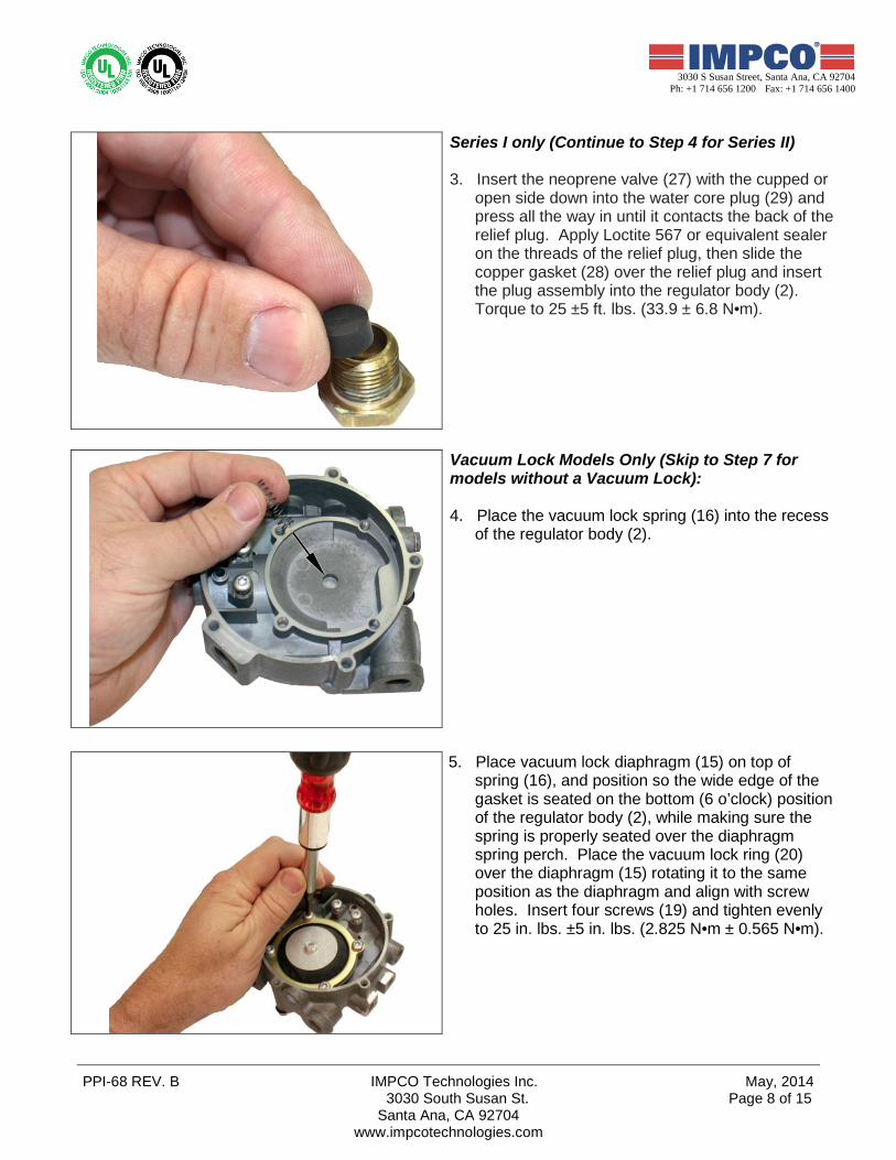
Series I only (Continue to Step 4 for Series II) 3. Insert the neoprene valve (27) with the cupped or
open side down into the water core plug (29) and press all the way in until it contacts the back of the relief plug. Apply Loctite 567 or equivalent sealer on the threads of the relief plug, then slide the copper gasket (28) over the relief plug and insert the plug assembly into the regulator body (2). Torque to 25 ±5 ft. lbs. (33.9 ± 6.8 N•m).
Vacuum Lock Models Only (Skip to Step 7 for models without a Vacuum Lock): 4. Place the vacuum lock spring (16) into the recess
of the regulator body (2).
5. Place vacuum lock diaphragm (15) on top of spring (16), and position so the wide edge of the gasket is seated on the bottom (6 o’clock) position of the regulator body (2), while making sure the spring is properly seated over the diaphragm spring perch. Place the vacuum lock ring (20) over the diaphragm (15) rotating it to the same position as the diaphragm and align with screw holes. Insert four screws (19) and tighten evenly to 25 in. lbs. ±5 in. lbs. (2.825 N•m ± 0.565 N•m).
March, 2015 IMPCO Technologies Inc. PPI-68 REV. C 3030 South Susan St. Page 9 of 15
Santa Ana, CA 92704 www.impcotechnologies.com
3030 S Susan Street, Santa Ana, CA 92704 Ph: +1 714 656 1200 Fax: +1 714 656 1400
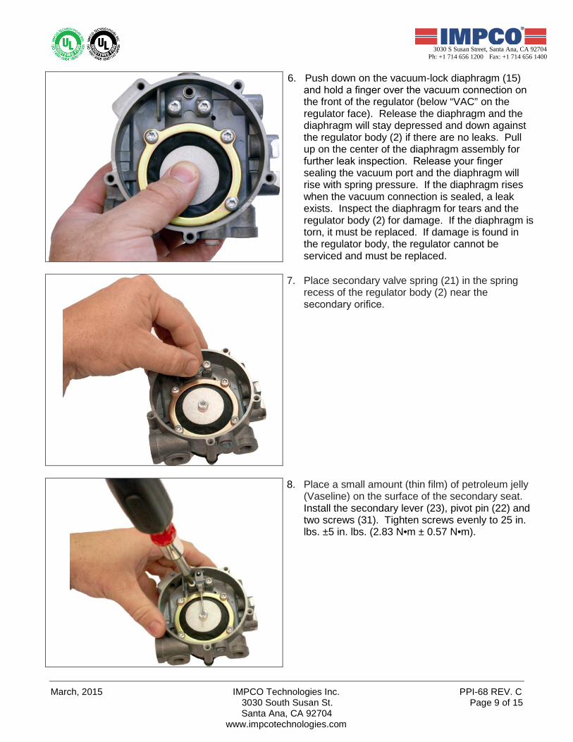
6. Push down on the vacuum-lock diaphragm (15) and hold a finger over the vacuum connection on the front of the regulator (below “VAC” on the regulator face). Release the diaphragm and the diaphragm will stay depressed and down against the regulator body (2) if there are no leaks. Pull up on the center of the diaphragm assembly for further leak inspection. Release your finger sealing the vacuum port and the diaphragm will rise with spring pressure. If the diaphragm rises when the vacuum connection is sealed, a leak exists. Inspect the diaphragm for tears and the regulator body (2) for damage. If the diaphragm is torn, it must be replaced. If damage is found in the regulator body, the regulator cannot be serviced and must be replaced.
7. Place secondary valve spring (21) in the spring recess of the regulator body (2) near the secondary orifice.
8. Place a small amount (thin film) of petroleum jelly (Vaseline) on the surface of the secondary seat. Install the secondary lever (23), pivot pin (22) and two screws (31). Tighten screws evenly to 25 in. lbs. ±5 in. lbs. (2.83 N•m ± 0.57 N•m).
PPI-68 REV. B IMPCO Technologies Inc. May, 2014 3030 South Susan St. Page 10 of 15
Santa Ana, CA 92704 www.impcotechnologies.com
3030 S Susan Street, Santa Ana, CA 92704 Ph: +1 714 656 1200 Fax: +1 714 656 1400
9. Inspect the height of the secondary lever (23). Using a ruler or straight edge, verify that the tip or end of the lever rod is level or flush with the top of the regulator body (2). If the lever requires adjusting, DO NOT bend while installed (bending may damage the valve seat). Remove the lever, bend, reinstall, then recheck lever height.
10. Lay the regulator body (2) flat on a clean working surface with the primary section up. Place the primary spring (8) in the recess as shown.
NOTE: Repair kit T60-RK does not include the primary spring; T60-RBK does.
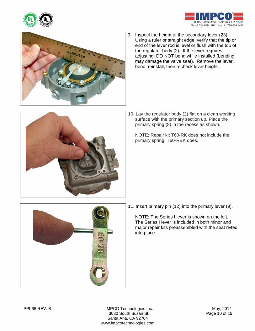
11. Insert primary pin (12) into the primary lever (9).
NOTE: The Series I lever is shown on the left. The Series I lever is included in both minor and major repair kits preassembled with the seat rivted into place.
March, 2015 IMPCO Technologies Inc. PPI-68 REV. C 3030 South Susan St. Page 11 of 15
Santa Ana, CA 92704 www.impcotechnologies.com
3030 S Susan Street, Santa Ana, CA 92704 Ph: +1 714 656 1200 Fax: +1 714 656 1400
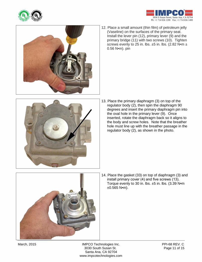
12. Place a small amount (thin film) of petroleum jelly (Vaseline) on the surfaces of the primary seat. Install the lever pin (12), primary lever (9) and the primary bridge (11) with two screws (10). Tighten screws evenly to 25 in. lbs. ±5 in. lbs. (2.82 N•m ± 0.56 N•m). pin
13. Place the primary diaphragm (3) on top of the regulator body (2), then spin the diaphragm 90 degrees and insert the primary diaphragm pin into the oval hole in the primary lever (9). Once inserted, rotate the diaphragm back so it aligns to the body and screw holes. Note that the breather hole must line up with the breather passage in the regulator body (2), as shown in the photo.
14. Place the gasket (33) on top of diaphragm (3) and install primary cover (4) and five screws (13). Torque evenly to 30 in. lbs. ±5 in. lbs. (3.39 N•m ±0.565 N•m).
PPI-68 REV. B IMPCO Technologies Inc. May, 2014 3030 South Susan St. Page 12 of 15
Santa Ana, CA 92704 www.impcotechnologies.com
3030 S Susan Street, Santa Ana, CA 92704 Ph: +1 714 656 1200 Fax: +1 714 656 1400
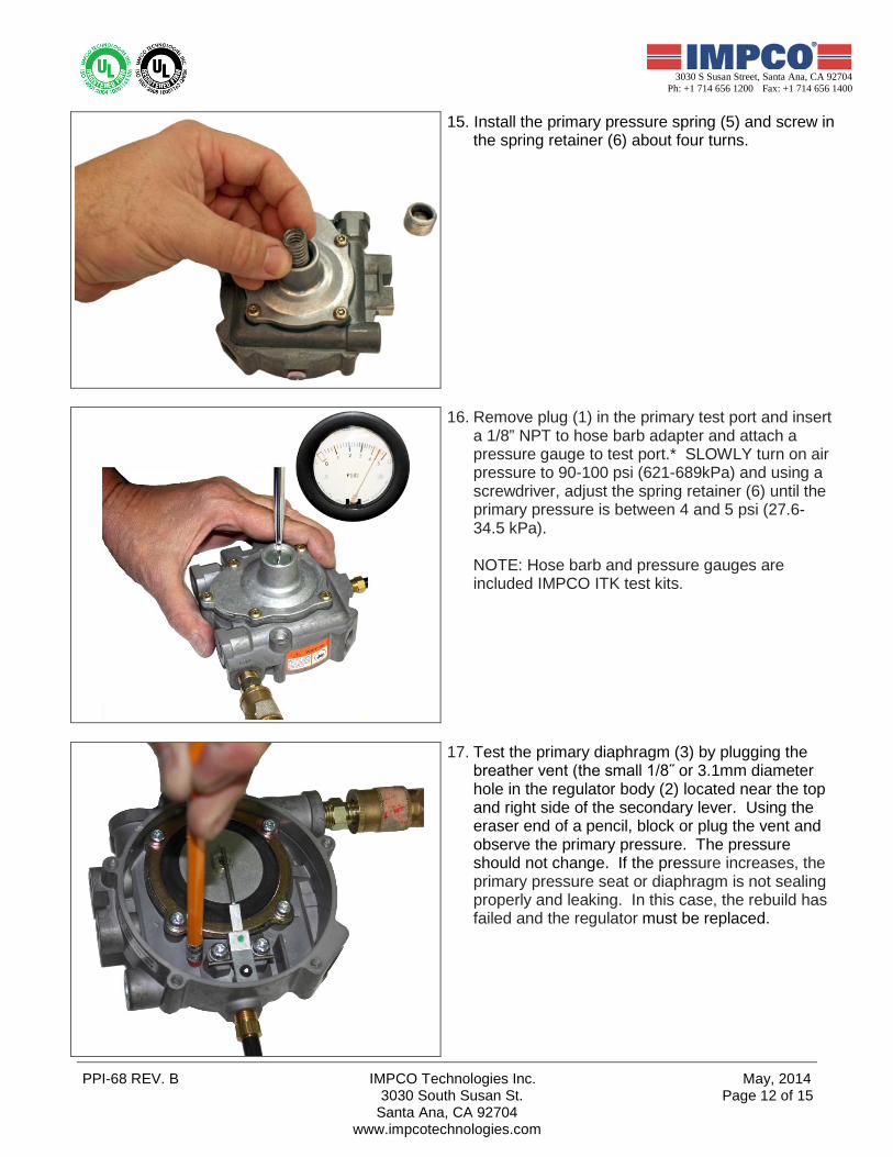
15. Install the primary pressure spring (5) and screw in the spring retainer (6) about four turns.
16. Remove plug (1) in the primary test port and insert a 1/8” NPT to hose barb adapter and attach a pressure gauge to test port.* SLOWLY turn on air pressure to 90-100 psi (621-689kPa) and using a screwdriver, adjust the spring retainer (6) until the primary pressure is between 4 and 5 psi (27.6-34.5 kPa).
NOTE: Hose barb and pressure gauges are included IMPCO ITK test kits.
17. Test the primary diaphragm (3) by plugging the breather vent (the small 1/8˝ or 3.1mm diameter hole in the regulator body (2) located near the top and right side of the secondary lever. Using the eraser end of a pencil, block or plug the vent and observe the primary pressure. The pressure should not change. If the pressure increases, the primary pressure seat or diaphragm is not sealing properly and leaking. In this case, the rebuild has failed and the regulator must be replaced.
March, 2015 IMPCO Technologies Inc. PPI-68 REV. C 3030 South Susan St. Page 13 of 15
Santa Ana, CA 92704 www.impcotechnologies.com
3030 S Susan Street, Santa Ana, CA 92704 Ph: +1 714 656 1200 Fax: +1 714 656 1400
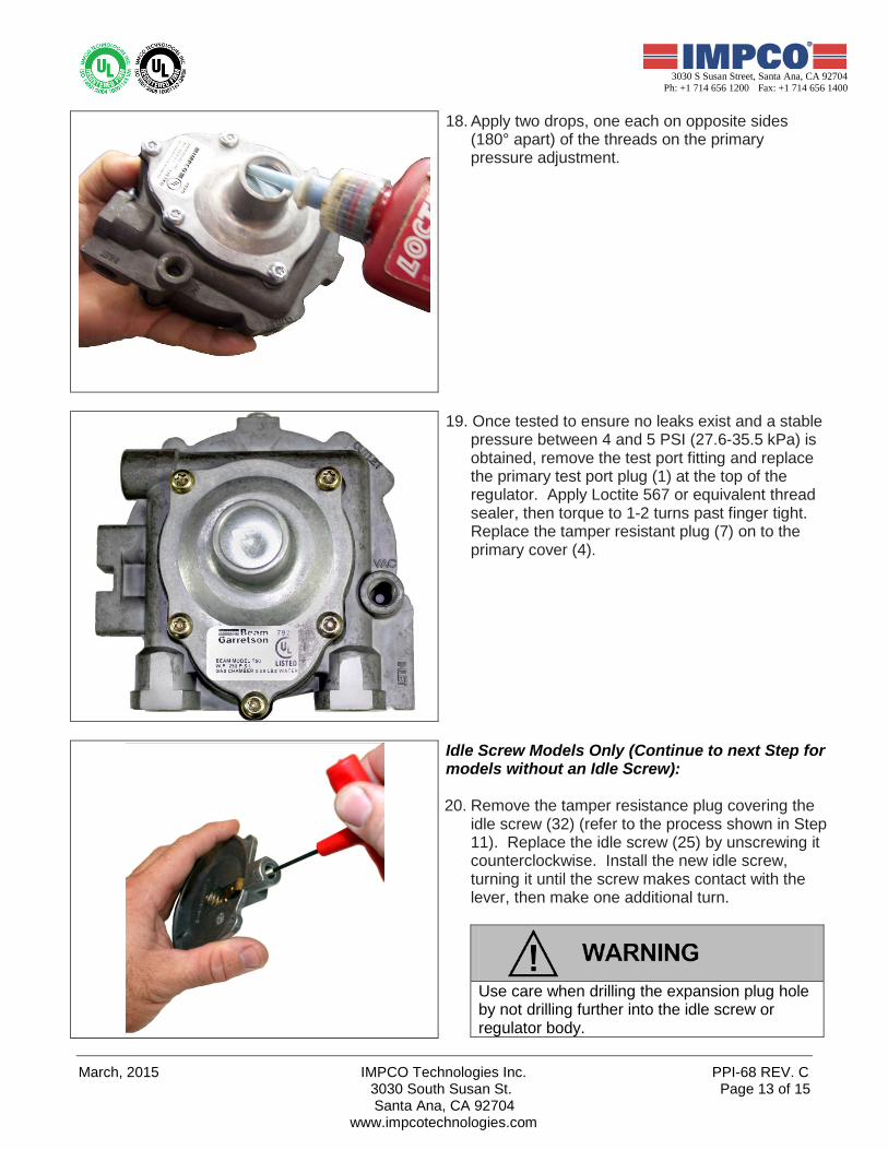
18. Apply two drops, one each on opposite sides (180° apart) of the threads on the primary pressure adjustment.
19. Once tested to ensure no leaks exist and a stable pressure between 4 and 5 PSI (27.6-35.5 kPa) is obtained, remove the test port fitting and replace the primary test port plug (1) at the top of the regulator. Apply Loctite 567 or equivalent thread sealer, then torque to 1-2 turns past finger tight. Replace the tamper resistant plug (7) on to the primary cover (4).
Idle Screw Models Only (Continue to next Step for models without an Idle Screw): 20. Remove the tamper resistance plug covering the
idle screw (32) (refer to the process shown in Step 11). Replace the idle screw (25) by unscrewing it counterclockwise. Install the new idle screw, turning it until the screw makes contact with the lever, then make one additional turn.
Use care when drilling the expansion plug hole by not drilling further into the idle screw or regulator body.
PPI-68 REV. B IMPCO Technologies Inc. May, 2014 3030 South Susan St. Page 14 of 15
Santa Ana, CA 92704 www.impcotechnologies.com
3030 S Susan Street, Santa Ana, CA 92704 Ph: +1 714 656 1200 Fax: +1 714 656 1400
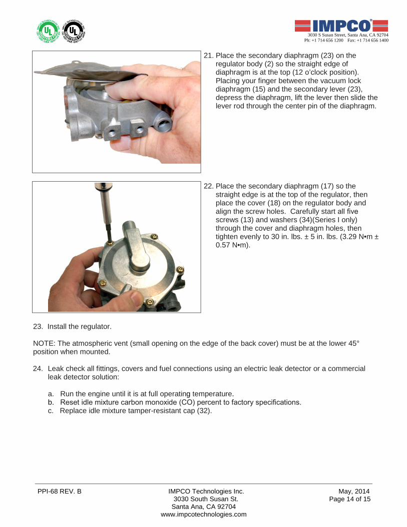
21. Place the secondary diaphragm (23) on the regulator body (2) so the straight edge of diaphragm is at the top (12 o’clock position). Placing your finger between the vacuum lock diaphragm (15) and the secondary lever (23), depress the diaphragm, lift the lever then slide the lever rod through the center pin of the diaphragm.
22. Place the secondary diaphragm (17) so the straight edge is at the top of the regulator, then place the cover (18) on the regulator body and align the screw holes. Carefully start all five screws (13) and washers (34)(Series I only) through the cover and diaphragm holes, then tighten evenly to 30 in. lbs. ± 5 in. lbs. (3.29 N•m ± 0.57 N•m).
23. Install the regulator. NOTE: The atmospheric vent (small opening on the edge of the back cover) must be at the lower 45° position when mounted.
24. Leak check all fittings, covers and fuel connections using an electric leak detector or a commercial
leak detector solution:
a. Run the engine until it is at full operating temperature. b. Reset idle mixture carbon monoxide (CO) percent to factory specifications. c. Replace idle mixture tamper-resistant cap (32).

March, 2015 IMPCO Technologies Inc. PPI-68 REV. C 3030 South Susan St. Page 15 of 15
Santa Ana, CA 92704 www.impcotechnologies.com
3030 S Susan Street, Santa Ana, CA 92704 Ph: +1 714 656 1200 Fax: +1 714 656 1400
WARNING: IMPROPER INSTALLATION OR USE OF THIS PRODUCT MAY CAUSE
SERIOUS INJURY AND/OR PROPERTY DAMAGE. SERVICE TECHNICIANS AND USERS SHOULD CAREFULLY READ AND ABIDE BY THE PROVISIONS SET FORTH IN NATIONAL FIRE PROTECTION ASSOCIATION PAMPHLET #37 FOR STATIONARY ENGINES, #52 FOR CNG VEHICULAR FUEL SYSTEMS OR #58 FOR LPG SYSTEMS. INSTALLERS LPG INSTALLATIONS IN THE UNITED STATES MUST BE DONE IN ACCORDANCE WITH FEDERAL, STATE AND LOCAL LAWS AND NATIONAL FIRE PROTECTION ASSOCIATION PAMPHLET #58, STANDARD FOR STORAGE AND HANDLING OF LIQUEFIED PETROLEUM GASES, TO THE EXTENT THESE STANDARDS ARE NOT IN VIOLATION OF FEDERAL, STATE OR LOCAL LAW. COUNTRIES OUTSIDE OF USA REFER TO THE GOVERNING AGENCIES OVERSEEING CNG AND PROPANE APPLICATIONS. CNG INSTALLATIONS IN THE UNITED STATES MUST BE DONE IN ACCORDANCE WITH FEDERAL, STATE AND LOCAL LAW AND NATIONAL FIRE PROTECTION ASSOCIATION PAMPHLET #52, COMPRESSED NATURAL GAS (CNG) VEHICULAR FUEL SYSTEMS, TO THE EXTENT THESE STANDARDS ARE NOT IN VIOLATION OF FEDERAL, STATE OR LOCAL LAW. LPG AND/OR NATURAL GAS INSTALLATIONS ON STATIONARY ENGINES MUST BE DONE IN ACCORDANCE WITH FEDERAL, STATE AND LOCAL LAW AND NATIONAL FIRE PROTECTION ASSOCIATION PAMPHLET #37, STATIONARY COMBUSTION ENGINES AND GAS TURBINE ENGINES, TO THE EXTENT THESE STANDARDS ARE NOT IN VIOLATION WITH FEDERAL, STATE OR LOCAL LAW. FAILURE TO ABIDE BY THE ABOVE WILL VOID ANY IMPCO WARRANTY ON THE PRODUCTS AND MAY CAUSE SERIOUS INJURY OR PROPERTY DAMAGE. SERVICE TECHNICIANS DUE TO THE INHERENT DANGER OF GASEOUS FUELS, IMPCO PRODUCTS SHOULD NOT BE INSTALLED OR USED BY PERSONS NOT KNOWLEDGEABLE OF THE HAZARDS ASSOCIATED WITH THE USE OF GASEOUS FUELS. ANY MAINTENANCE, SERVICE OR REPAIR SHOULD BE PERFORMED BY TRAINED AND EXPERIENCED SERVICE TECHNICIANS. PROPER TOOLS AND EQUIPMENT PROPER TOOLS AND EQUIPMENT SHOULD BE USED TO PREVENT INJURY TO THE SERVICING TECHNICIAN, PROPERTY OR SYSTEM COMPONENTS. SERVICE REPAIRS SHOULD ALWAYS BE PERFORMED IN A SAFE ENVIRONMENT AND THE TECHNICIAN SHOULD ALWAYS WEAR PROTECTIVE CLOTHING TO PREVENT INJURY. INSPECT BEFORE USE ALWAYS INSPECT THE MAJOR CASTING PIECES FOR DAMAGE, CORROSION OR CRACKS BEFORE ATTEMPTING A SERVICE REPAIR. BE SURE THE REPAIR KIT PART NUMBER YOU ARE USING IS CORRECT FOR THE COMPONENT(S) BEING SERVICED. NO TEFLON TAPE DO NOT USE TEFLON TAPE TO SEAL ANY FUEL FITTINGS. FAILURE TO FOLLOW THIS WARNING MAY CAUSE THE REGULATOR TO LEAK INTERNALLY, POSSIBLY RESULTING IN SERIOUS INJURY, DEATH AND/OR PROPERTY DAMAGE AND MAY VOID ANY WARRANTY COVERAGE.