T3 Mixer Primer - Marki Microwave · T3 Mixer Primer A Tutorial on High Linearity / High IP3 RF &...
17
T3 Mixer Primer A Tutorial on High Linearity / High IP3 RF & Microwave Mixers By Ferenc Marki & Christopher Marki, Ph.D. Intermodulation distortion (IMD) suppression is a critical issue in modern military and commercial RF/microwave systems. Pressed by the demands imposed by distortion-sensitive digital modulation formats, modern systems routinely specify linearity requirements that are impossible to attain using conventional approaches. To meet these new challenges, Marki Microwave has introduced the Two-Tone-Terminator (T3) mixer family. The T3 mixer is the most sophisticated mixer circuit on the market today and offers unparalleled performance when compared to all other mixer technologies. This Primer describes the key operating principles of the T3 mixer and compares the performance against traditional double balanced mixers. Section 1. T3 Mixer Overview The T3 mixer possesses the following properties: 1. Low conversion loss and extremely wide bandwidth. Typical conversion loss is 7 dB with a bandwidth of 10 MHz to 12 GHz. 2. Unparalleled IMD suppression. Input third order intercept (IIP3) performance is typically 10 dB higher than the LO drive across the band. IIP3 values as high as 20 dB above the LO drive have been witnessed in lab. 3. High 1 dB compression point. The T3 compression point is approximately 1-3 dB below the LO drive level. Conventional mixers compress 5-7 dB below the LO drive level.
-
Upload
phungthuan -
Category
Documents
-
view
243 -
download
4
Transcript of T3 Mixer Primer - Marki Microwave · T3 Mixer Primer A Tutorial on High Linearity / High IP3 RF &...

T3 Mixer Primer
A Tutorial on High Linearity / High IP3 RF & Microwave Mixers
By Ferenc Marki
& Christopher Marki, Ph.D.
Intermodulation distortion (IMD) suppression is a critical issue in modern military and
commercial RF/microwave systems. Pressed by the demands imposed by distortion-sensitive
digital modulation formats, modern systems routinely specify linearity requirements that are
impossible to attain using conventional approaches. To meet these new challenges, Marki
Microwave has introduced the Two-Tone-Terminator (T3) mixer family. The T3 mixer is the
most sophisticated mixer circuit on the market today and offers unparalleled performance when
compared to all other mixer technologies. This Primer describes the key operating principles of
the T3 mixer and compares the performance against traditional double balanced mixers.
Section 1. T3 Mixer Overview
The T3 mixer possesses the following properties:
1. Low conversion loss and extremely wide bandwidth. Typical conversion loss is 7 dB with
a bandwidth of 10 MHz to 12 GHz.
2. Unparalleled IMD suppression. Input third order intercept (IIP3) performance is typically
10 dB higher than the LO drive across the band. IIP3 values as high as 20 dB above the
LO drive have been witnessed in lab.
3. High 1 dB compression point. The T3 compression point is approximately 1-3 dB below
the LO drive level. Conventional mixers compress 5-7 dB below the LO drive level.

Marki Microwave | 215 Vineyard Ct. | Morgan Hill, CA 95037 | PH 408.778.4200 | [email protected]
4. LO drive level flexibility. A T3 mixer’s conversion loss is constant for LO drives ranging
from +12 dBm through +25 dBm. As LO drive increases, 1 dB compression and IMD
performance improve nearly dB for dB. No other mixer exhibits this unique property.
5. T3 mixer performance optimizes with a square-wave LO drive.
Two key breakthroughs enable the T3 mixer: the use of near-ideal commutating
behavior and the employment of internal feedback circuitry. It has been known for over half a
century that commutating (i.e. switching) mixers produce ideal IMD behavior. In switching
mixers, the unwanted nonlinear characteristics of the diode are minimized such that only the
LO is capable of turning the diode ON and OFF. When combined with square-wave LO drive, the
linearity of the commutating mixer is additionally improved because the switching is allowed to
occur nearly instantaneously. The T3, as it will be demonstrated, combines switching behavior
and square-wave drive to achieve unparalleled linear performance.
T3 performance is enhanced by its novel circuit design. Standard double balanced
mixers operate with a prescribed LO drive level that optimizes performance over a 3 dB range.
Outside of this recommended range, unexpected problems can manifest, especially in terms of
nonlinear performance. In most systems, the engineer must use caution and ensure that the
proper LO drive is applied. The sensitivity of traditional double balanced mixers to LO drive can
cause increased design time, hardware cost, and complexity.1 For the T3, however, the
sensitivity of the mixer to LO drive is eliminated by using a novel passive feedback scheme. In
essence, the T3 can “sense” the amount of LO being applied and adjust the switching level
accordingly. Therefore, the same T3 can be used at +15 dBm drive and +25 dBm drive, without
1 We have found from experience that customers sometimes make the assumption that driving
the LO at a lower-than-recommended level is an acceptable practice, as long as the system can
handle the increased conversion loss. In truth, one should never make such a design tradeoff
because nearly every other mixer property (isolation, IIP3, spurious response, 1 dB
compression, etc..) will suffer in unpredictable and unrepeatable ways. The idea that a lower LO
drive can improve IIP3 over narrow frequency bands has been perpetuated in the industry [1]
but is a practice that Marki Microwave cautions against. The nonlinearity of a mixer below the
recommended LO drive level depends on the individual diode characteristics, circuit tolerances
and temperature. Experimental studies show that unit to unit variances combined with
temperature fluctuations can cause unexpected mixer behavior that is difficult to control
reliably. The only proven method to ensure success is to drive the double balanced mixer at the
vendor recommended drive levels.

Marki Microwave | 215 Vineyard Ct. | Morgan Hill, CA 95037 | PH 408.778.4200 | [email protected]
affecting the conversion loss significantly. Moreover, as the LO is increased, the 1 dB
compression and IMD performance of the T3 actually improve.
VIF
+
-
VLO
VRF
Voltage
Cu
rren
t
Voltage
Cu
rren
t
Ideal Commutator Actual Schottky Diode
(c)(b)
(a)
Transition Region
Fig. 1. (a) Simple single ended mixer. I-V characteristics for (b) the ideal commutator
and (c) a realistic Schottky diode.
The T3’s unmatched performance is vividly illustrated in the following Sections. We
begin by demonstrating the performance of a single ended diode mixer subject to sine wave
and square-wave LO drive. We show that the nonlinear behavior of the diode can be accurately
modeled using a simple set of assumptions and that a square-wave drive is critical for mixer
linearity. We then demonstrate T3 performance in terms of conversion loss, 1 dB compression,
and IMD and compare the results to the common double balanced mixer. In nearly all
categories, the T3 is shown to have superior performance and that the square-wave LO drive
can significantly improve mixer linearity.
Section 2. Single Diode Mixer: Theory and Experiment
The concept of the switching mixer was previously described in the Marki Microwave
application note Mixer Basics Primer [2]. This Section builds on the concepts for the Primer with
a focus on modeling and experimental results. We begin by discussing the nonlinear
performance of a single diode (i.e. unbalanced) mixer to simplify the analysis.
The circuit under analysis is shown in Fig. 1. As was discussed in the Mixer Basics Primer,
the transition region of the diode is largely responsible for generating unwanted IMD. When
the RF tone rivals the strength of the LO signal, the diode no longer behaves as an ideal switch
and high levels of IMD are generated in this transition region. Incidentally, many text books
(e.g. [3]) describe that frequency conversion in a mixer is enabled by the nonlinear interaction
Marki Microwave | 215 Vineyard Ct. | Morgan Hill, CA 95037 | PH 408.778.4200 | [email protected]
of the RF and LO on the diode transition region and that the process is best described by a
Taylor series expansion. We believe this is a flawed approach because it masks the fundamental
understanding of diode mixers as switching mixers. Experience has shown that the goal is to
minimize the interaction of the RF and LO in the diode transition region because frequency
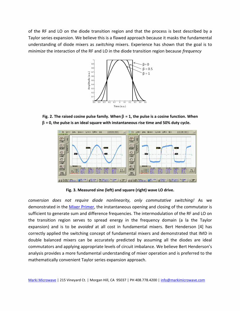
Fig. 2. The raised cosine pulse family. When = 1, the pulse is a cosine function. When
= 0, the pulse is an ideal square with instantaneous rise time and 50% duty cycle.
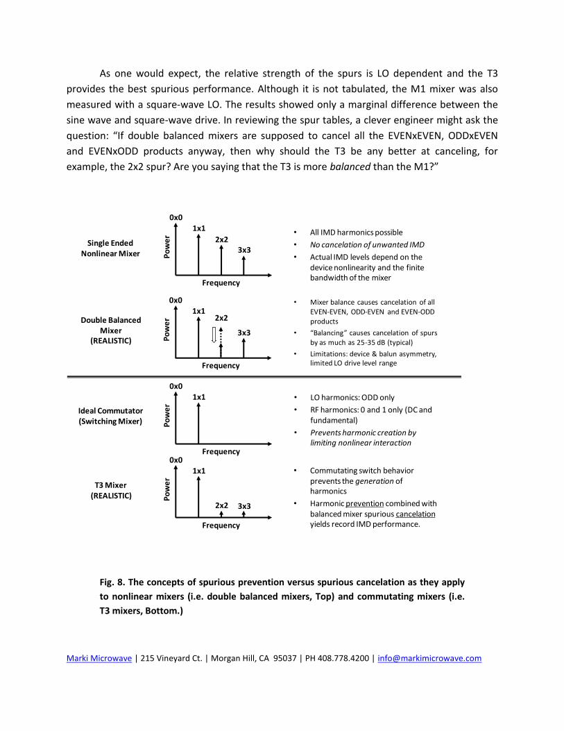
Fig. 3. Measured sine (left) and square (right) wave LO drive.
conversion does not require diode nonlinearity, only commutative switching! As we
demonstrated in the Mixer Primer, the instantaneous opening and closing of the commutator is
sufficient to generate sum and difference frequencies. The intermodulation of the RF and LO on
the transition region serves to spread energy in the frequency domain (a la the Taylor
expansion) and is to be avoided at all cost in fundamental mixers. Bert Henderson [4] has
correctly applied the switching concept of fundamental mixers and demonstrated that IMD in
double balanced mixers can be accurately predicted by assuming all the diodes are ideal
commutators and applying appropriate levels of circuit imbalance. We believe Bert Henderson’s
analysis provides a more fundamental understanding of mixer operation and is preferred to the
mathematically convenient Taylor series expansion approach.

Marki Microwave | 215 Vineyard Ct. | Morgan Hill, CA 95037 | PH 408.778.4200 | [email protected]
When the LO alone controls the diode conductance, the mixer approximates the ideal
switching behavior. As one might expect, the faster the LO passes through the transition region,
the more linear the mixer becomes. Essentially, the role of the LO is to force the diode to be
fully short (ON) or fully open (OFF). The time it takes the LO to swing the diode on and off is
associated with the rise time of the LO waveform. The common sine wave LO drive waveform
has a rise time on the order of 30% of the total period (e.g. 300 ps for a 1 GHz sine wave LO).
Fig. 4. Calculated and measured spurious response for a single diode mixer driven by a
sine wave (left) and a square-wave (right). “X” marks represent measured data points.
Employing a square-wave LO drive can significantly improve the LO rise/fall time and
thus reduce the IMD generated in the diode transition region. Conveniently, both sine wave
and square-wave LO drives can be modeled using the well known raised cosine pulse shape.
Raised cosine pulses are convenient for two reasons. First, the transition between the sine and
square-wave pulse shape is controlled by a single parameter, . When = 1, the LO is a sine
wave. When = 0, the LO is a perfect square-wave (i.e. instantaneous rise time). Second, as
sweeps between 0 and 1, different rise/fall times can be tailored. For example, when = 0.5,
the rise time of the raised cosine pulse is about 15% of the pulse period. Control over the pulse
rise time using the parameter makes the raised cosine pulse a convenient waveform for
modeling the finite rise time of realistic square-waves.
A single diode mixer was constructed to demonstrate experimentally the impact of LO
rise time on mixer IMD. The LO waveforms are shown in Fig. 3. Both LO waveforms had a peak-
peak voltage swing of about 2 V, as measured by a 70 GHz sampling oscilloscope. The sine wave
rise time was measured to be about 270 ps, corresponding to a percent rise time of 27% at 1
GHz. The square-wave rise time was measured to be 50 ps, corresponding to a percent rise time
of 5% at 1 GHz. The square-wave was created using the Marki Microwave A-0010EZP square-
wave LO driver amplifier.

Marki Microwave | 215 Vineyard Ct. | Morgan Hill, CA 95037 | PH 408.778.4200 | [email protected]
A simple MATLAB script was used to predict the single tone spurious performance of the
single diode mixer in the presence of sine and square-wave LO. The LO waveform was modeled
as a pure sine wave (= 1) and as a square-wave ( = 0.17). The value of = 0.17 corresponds
to a 5% rise time raised cosine pulse. The diode I-V characteristics were taken from the
measured Schottky diode in Fig. 1c. The spurious response was found by taking the Fourier
transform of the resulting IF current.
Fig. 5. Calculated and measured two-tone response for a single diode mixer driven by
a sine wave (left) and a square-wave (right). “X” marks represent measured data
points.
A simple downconversion was performed to measure the spurious performance on a
spectrum analyzer. The results are shown in Fig. 4. The curves show the predicted spurious
performance as calculated by the MATLAB script and the black “X’s” show the measured values
for the 2x2, 3x3, 4x4 and 5x5 spurious tones. The results clearly demonstrate that for the same
peak-peak voltage swing, the square-wave significantly outperforms the sine wave. The reason
is that the square-wave switches the diode as a near-ideal commutator and prevents the RF and
LO from intermodulating over the transition region of the diode. For all spurs measured, the
square-wave improves performance on the average of 15-20 dB!
Two-tone performance was also measured as shown in Fig. 5. Again, the square-wave
enables significantly enhanced mixer linearity. As is clearly shown, the square-wave
outperforms the sine wave drive, even when the sine wave is several dB larger.

Marki Microwave | 215 Vineyard Ct. | Morgan Hill, CA 95037 | PH 408.778.4200 | [email protected]
Clearly, operating the mixer diode as a commutator helps to prevent nonlinear
intermodulation from being generated in the diode transition region. By providing mixer
balance, much of the remaining IMD can be canceled as previously described in the Mixer
Basics Primer. The T3 mixer makes use of both of these concepts—harmonic prevention
through diode commutation and spurious cancelation through mixer balance—to achieve its
unmatched performance.
Section 3. T3 Mixers VS. Double Balanced Mixers
The most common commercially available mixer is the double balanced mixer. The
double balanced mixer is known for its high isolation, DC IF capability, and excellent conversion
loss. Since the 1960s, double balanced mixers have been the workhorse mixer for the
microwave industry. Indeed, since the early 1990’s, Marki Microwave has shipped more M1
double balanced mixers than all others combined.
Owing to the ubiquity of double balanced mixers in the microwave/RF industry, it seems
appropriate, then, to compare their design with that of the T3 mixer. In the following sections,
experimental measurements illustrate the key differences between the M1 and T3 mixers and
highlight the significant design advantages afforded by the latter.
Section 3.1 Conversion Loss
As was previously explained in the Mixer Primer, conversion loss is a critical mixer
metric because it is an indication of how efficiently the mixer converts frequencies. Conversion
loss is additionally important because it can be used as a diagnostic measurement for other key
mixer metrics such as isolation. In other words, if the conversion loss is poor, then other mixer
metrics can be inferred to be poor as well.
The conversion loss curves for the M1 and T3 mixers are shown in Fig. 6. As a basis of
comparison, we focus on the 2-4 GHz band because this is a common area of interest for many
customers and applications. The conversion loss measurement is a constant IF downconversion
where the LO and RF sources are swept with a constant 15 MHz offset. This is the standard
technique employed by Marki Microwave to measure conversion loss for all prototype and
production level mixers. Note that each mixer is measured with both a sine wave and a square-
wave LO— the sine wave LO is generated by a synthesizer and the square-wave is generated by
a Marki Microwave AP-0010EZP single positive bias square-wave amplifier. We found the AP-
0010EZP amplifier to be particularly convenient during measurement because the overall
amplifier output could be easily tuned by changing the single positive bias from about +4 V to
+8 V without worrying about the cumbersome negative bias of most wideband amplifiers. We

Marki Microwave | 215 Vineyard Ct. | Morgan Hill, CA 95037 | PH 408.778.4200 | [email protected]
also found that the rise time and overall pulse shape of the AP-0010EZP square-waves
remained constant for all bias points.
As was mentioned previously, the DBM (i.e. the M1 mixer) has the lower conversion
loss of the two measured mixers due to its highly efficient, low loss design. This trend is
confirmed in Fig. 6 when the M1 is driven by a 9 dBm sine wave (an appropriate drive level for a
Fig. 6. Conversion loss for sine and square-wave LO for the M1 (left) and T3 (right)
mixers. Notice that the M1 mixer is more sensitive to the LO, especially for high level
drives. The T3 has a flatter, more robust conversion loss as a function of LO.
low barrier “L” diode quad). Even when the M1 is over-driven with a +19 dBm sine wave, the
conversion loss is an outstanding 5.5 dB. However, when a square-wave is applied, the M1
conversion loss suffers considerably. For the highest square-wave drive measured2 (+19 dBm),
the M1 conversion loss increases by as much as 2 dB! As will become the general trend, the
traditional double balanced mixer actually deteriorates with a square-wave drive. We have
found this trend to be consistently true for all commercially available DBMs, whether they are
produced by Marki or otherwise. We view this sensitivity of the DBM to square-wave drive to be
an inherent weakness of traditional double balanced mixers.
By comparison, the T3 has a slightly higher conversion loss but also shows less sensitivity
to LO drive. In fact, the variation in conversion loss is smaller than 1 dB for the sine and square-
wave LO, for all drive levels. Most importantly, results show that the conversion loss of the T3 is
highly insensitive to drive level when a square-wave is applied. The T3 also exhibits a flatter
conversion loss when compared to the M1.
2 Since most customers are unable to measure the peak to peak voltage of the square-wave, it
is more convenient to quote square-wave power. We define square-wave power as the power
measured in the fundamental frequency of the square-wave after all higher harmonics are
filtered using a lowpass filter.

Marki Microwave | 215 Vineyard Ct. | Morgan Hill, CA 95037 | PH 408.778.4200 | [email protected]
Section 3.2 1 dB Compression Point
The compression point of a mixer is described in the Mixer Basics Primer and relates to
how well the LO is able to control the conductance of the diodes, even in the presence of a
strong RF tone. When the RF begins to challenge the LO for control of the diode switching, the
mixer begins to compress (i.e. the conversion loss increases). Many engineers believe that
mixer compression can be avoided by increasing the LO drive. In reality, this reasoning is wrong
Fig. 7. 1 dB compression point as a function of LO drive power. Notice that M1
compression does not improve as LO is increased while the T3 improves almost
linearly.
assuming one is using a traditional double balanced mixer. The plots in Fig. 7 measure the 1 dB
compression point as a function of LO drive (again, for both sine and square-wave). M1 and T3
mixers exhibit vastly different behavior in terms of compression. For the M1 mixer, one finds
that the 1 dB compression is very weakly dependent on LO drive. As the LO sweeps from +10 to
+20 dBm, the 1 dB compression of the M1 mixer improves by, at best, 2 dB. The conventional
rule of thumb of a DBM is as follows: the 1 dB compression point will be 5-7 dB below the
largest recommended LO drive level. Since +10 dBm is the largest recommended drive for a low
barrier diode, the 1 dB compression point of the M1 will be somewhere between +3 and +5
dBm. This is confirmed by the results. Clearly, increasing the drive has a marginal impact on
compression.
On the other hand, the T3 shows an improvement in 1 dB compression point as LO is
increased. For a sine wave LO drive, the T3 compression point improves about 0.7 dB for every
dB increase in LO drive. When the square-wave LO is applied, the impact on 1 dB compression
is even more striking. For the T3, the square-wave improves the compression by 3-4 dB as
compared to the sine wave! In fact, the T3 compression point improves so drastically with the

Marki Microwave | 215 Vineyard Ct. | Morgan Hill, CA 95037 | PH 408.778.4200 | [email protected]
square-wave that the dynamic range of the measurement equipment limits the results for
square-wave drive above +18 dBm (i.e. 5 Vpp).
Section 3.3 Single-tone Intermodulation
Most engineers are comfortable with the notion that balanced mixers cancel some of
the IMD products. As was discussed in the Mixer Basics Primer, double balanced mixers are
designed specifically to cancel all EVEN-EVEN, EVEN-ODD and ODD-EVEN single tone products.
The level to which these products are canceled depends on the balance of the overall mixer
DOUBLE-BALANCED: M1/M3/M4/M8/M9 (L & M Diodes)
Spurious Suppression (Typical) - dBc
5R 100 100 90 110 95
4R 80 95 95 100 90
RF Input @ -10 dBm 3R 50 70 55 70 60
2R 55 50 50 50 50
1R --- 20 10 25 20
1L 2L 3L 4L 5L
TABLE 1. Double Balanced Spur Table: Sine wave LO.
TRIPLE-BALANCED: T3’s – Sine-Wave LO-Drive
Spurious Suppression (Typical) - dBc
4R 100 100 100 100 100
RF Input @ -10 dBm 3R 90 100 75 90 90
LO Input @ +25 dBm 2R 70 55 70 70 75
1R --- 20 10 20 15
1L 2L 3L 4L 5L
TRIPLE-BALANCED: T3’s – Square-Wave LO-Drive
Spurious Suppression (Typical) - dBc
4R 100 100 100 100 100
RF Input @ -10 dBm 3R 100 100 100 100 100
LO Input @ +25 dBm 2R 80 90 90 90 90
1R --- 40 15 30 20
1L 2L 3L 4L 5L
TABLE 2. T3 Spur Table: Sine wave and Square-wave LO.
circuit. In order to predict the relative strength of a particular spurious product, mixer “spur
tables” can be used which tabulate the magnitude of all NxM products. Marki Microwave spur
tables for double balanced and T3 mixers are shown in TABLE 1 and TABLE 2.
Marki Microwave | 215 Vineyard Ct. | Morgan Hill, CA 95037 | PH 408.778.4200 | [email protected]
As one would expect, the relative strength of the spurs is LO dependent and the T3
provides the best spurious performance. Although it is not tabulated, the M1 mixer was also
measured with a square-wave LO. The results showed only a marginal difference between the
sine wave and square-wave drive. In reviewing the spur tables, a clever engineer might ask the
question: “If double balanced mixers are supposed to cancel all the EVENxEVEN, ODDxEVEN
and EVENxODD products anyway, then why should the T3 be any better at canceling, for
example, the 2x2 spur? Are you saying that the T3 is more balanced than the M1?”
Frequency
0x01x1
2x2
Po
we
r
3x3
Frequency
0x01x1
2x2
Po
we
r
3x3Single Ended
Nonlinear Mixer
Double BalancedMixer
(REALISTIC)
Frequency
0x01x1
2x2
Po
we
r
3x3
T3 Mixer(REALISTIC)
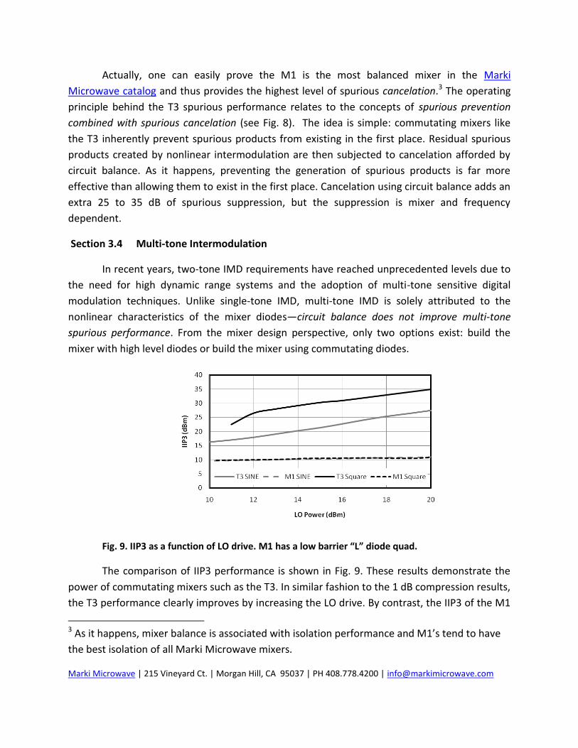
• All IMD harmonics possible
• No cancelation of unwanted IMD
• Actual IMD levels depend on the device nonlinearity and the finite bandwidth of the mixer
• Mixer balance causes cancelation of all EVEN-EVEN, ODD-EVEN and EVEN-ODD products
• “Balancing” causes cancelation of spurs by as much as 25-35 dB (typical)
• Limitations: device & balun asymmetry, limited LO drive level range
• Commutating switch behavior prevents the generation of harmonics
• Harmonic prevention combined with balanced mixer spurious cancelation yields record IMD performance.
Frequency
0x01x1
Po
we
r
Ideal Commutator(Switching Mixer)
• LO harmonics: ODD only
• RF harmonics: 0 and 1 only (DC and fundamental)
• Prevents harmonic creation by limiting nonlinear interaction
Fig. 8. The concepts of spurious prevention versus spurious cancelation as they apply
to nonlinear mixers (i.e. double balanced mixers, Top) and commutating mixers (i.e.
T3 mixers, Bottom.)
Marki Microwave | 215 Vineyard Ct. | Morgan Hill, CA 95037 | PH 408.778.4200 | [email protected]
Actually, one can easily prove the M1 is the most balanced mixer in the Marki
Microwave catalog and thus provides the highest level of spurious cancelation.3 The operating
principle behind the T3 spurious performance relates to the concepts of spurious prevention
combined with spurious cancelation (see Fig. 8). The idea is simple: commutating mixers like
the T3 inherently prevent spurious products from existing in the first place. Residual spurious
products created by nonlinear intermodulation are then subjected to cancelation afforded by
circuit balance. As it happens, preventing the generation of spurious products is far more
effective than allowing them to exist in the first place. Cancelation using circuit balance adds an
extra 25 to 35 dB of spurious suppression, but the suppression is mixer and frequency
dependent.
Section 3.4 Multi-tone Intermodulation
In recent years, two-tone IMD requirements have reached unprecedented levels due to
the need for high dynamic range systems and the adoption of multi-tone sensitive digital
modulation techniques. Unlike single-tone IMD, multi-tone IMD is solely attributed to the
nonlinear characteristics of the mixer diodes—circuit balance does not improve multi-tone
spurious performance. From the mixer design perspective, only two options exist: build the
mixer with high level diodes or build the mixer using commutating diodes.
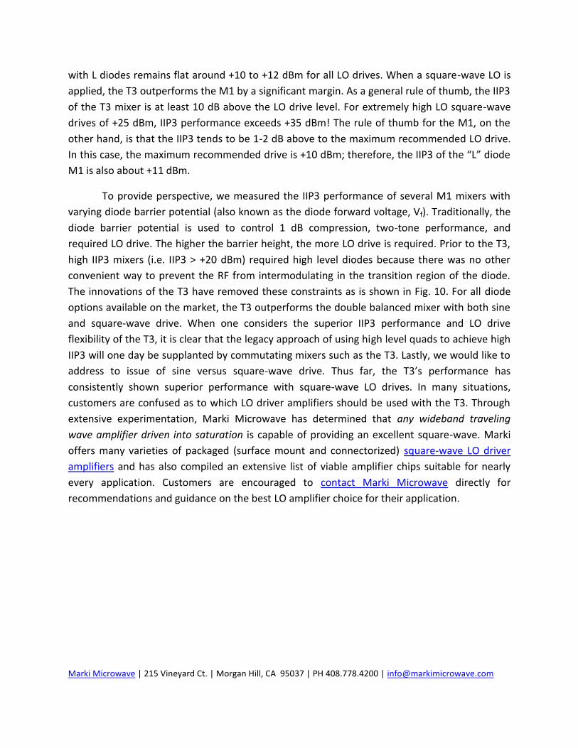
Fig. 9. IIP3 as a function of LO drive. M1 has a low barrier “L” diode quad.
The comparison of IIP3 performance is shown in Fig. 9. These results demonstrate the
power of commutating mixers such as the T3. In similar fashion to the 1 dB compression results,
the T3 performance clearly improves by increasing the LO drive. By contrast, the IIP3 of the M1
3 As it happens, mixer balance is associated with isolation performance and M1’s tend to have
the best isolation of all Marki Microwave mixers.
Marki Microwave | 215 Vineyard Ct. | Morgan Hill, CA 95037 | PH 408.778.4200 | [email protected]
with L diodes remains flat around +10 to +12 dBm for all LO drives. When a square-wave LO is
applied, the T3 outperforms the M1 by a significant margin. As a general rule of thumb, the IIP3
of the T3 mixer is at least 10 dB above the LO drive level. For extremely high LO square-wave
drives of +25 dBm, IIP3 performance exceeds +35 dBm! The rule of thumb for the M1, on the
other hand, is that the IIP3 tends to be 1-2 dB above to the maximum recommended LO drive.
In this case, the maximum recommended drive is +10 dBm; therefore, the IIP3 of the “L” diode
M1 is also about +11 dBm.
To provide perspective, we measured the IIP3 performance of several M1 mixers with
varying diode barrier potential (also known as the diode forward voltage, Vf). Traditionally, the
diode barrier potential is used to control 1 dB compression, two-tone performance, and
required LO drive. The higher the barrier height, the more LO drive is required. Prior to the T3,
high IIP3 mixers (i.e. IIP3 > +20 dBm) required high level diodes because there was no other
convenient way to prevent the RF from intermodulating in the transition region of the diode.
The innovations of the T3 have removed these constraints as is shown in Fig. 10. For all diode
options available on the market, the T3 outperforms the double balanced mixer with both sine
and square-wave drive. When one considers the superior IIP3 performance and LO drive
flexibility of the T3, it is clear that the legacy approach of using high level quads to achieve high
IIP3 will one day be supplanted by commutating mixers such as the T3. Lastly, we would like to
address to issue of sine versus square-wave drive. Thus far, the T3’s performance has
consistently shown superior performance with square-wave LO drives. In many situations,
customers are confused as to which LO driver amplifiers should be used with the T3. Through
extensive experimentation, Marki Microwave has determined that any wideband traveling
wave amplifier driven into saturation is capable of providing an excellent square-wave. Marki
offers many varieties of packaged (surface mount and connectorized) square-wave LO driver
amplifiers and has also compiled an extensive list of viable amplifier chips suitable for nearly
every application. Customers are encouraged to contact Marki Microwave directly for
recommendations and guidance on the best LO amplifier choice for their application.

Marki Microwave | 215 Vineyard Ct. | Morgan Hill, CA 95037 | PH 408.778.4200 | [email protected]
Fig. 10. T3 two-tone compared to M1 two-tone for various diode types. Markers correspond to
IIP3 of the M1 mixers driven with recommended sine wave LO. The T3 is constructed with L
diodes.
As a final study, we demonstrate the IIP3 performance of the T3 as a function of square-wave
rise time. Much in the same way that the raised cosine pulse can be used to tailor the rise time
of the square-wave (Section 2), a Marki Microwave WavefadeTM lowpass filter can be used to
modify the rise time of a pulse. The Wavefade filter [5] is quasi-infinite element Bessel shaped
filter which possesses ultra-flat group delay performance. Owing to the extremely flat group
delay, the Wavefade is ideally suited to reduce the bandwidth (i.e. increase the rise time) of
high speed pulses, digital bit sequences, and, in this case, square-wave LO waveforms. By
connecting Wavefade filters to the AP-0010EZP amplifier with cutoff frequencies ranging from
2.8 GHz to 17.5 GHz, we experimentally controlled the rise time of the LO waveform. Left
unfiltered, the AP-0010EZP amplifer measured a rise time of 18 ps at 3 GHz (equating to a
raised cosine pulse of = 0.18). With a Wavefade filter with 7.47 GHz cutoff connected to the
amplifier, the rise time increases to 48 ps (equating to a raised cosine pulse of = 0.49). When
the Wavefade filter cutoff is reduced to 4.65 GHz, the rise time increases to 80 ps (equating to a
raised cosine pulse of = 0.81). The unfiltered, 7.47 GHz filtered and 4.65 GHz filtered square-
wave oscilloscope traces are shown in Fig. 11. One should note the striking similarity of the
experimental pulses in Fig. 11 with those of the raised cosine pulses from Fig. 2. The excellent
pulse symmetry and nonexistent pulse ringing is attributed to the excellent group delay
response of the Wavefade lowpass filters.

Marki Microwave | 215 Vineyard Ct. | Morgan Hill, CA 95037 | PH 408.778.4200 | [email protected]
18 ps
48 ps
80 ps
Fig. 11. LO square-wave with varying rise time. Unfiltered rise time is 18 ps. Rise times of 48 ps
and 80 ps correspond to Wavefade lowpass cutoff frequencies of 7.47 GHz and 4.65 GHz,
respectively.
Fig. 12. IIP3 versus square-wave rise time.
The two-tone performance of the T3 as a function of rise time is shown in Fig. 12. As
expected, the unfiltered, fast rise time square-wave drive yields a two-tone performance
exceeding +32.5 dBm. As the square-wave drive is more heavily lowpass filtered, the IIP3
decreases. In the limit that all the higher order harmonics of the square-wave are filtered using
the lowpass filter, the square-wave reduces to a sine wave. In Fig. 12, a 3 GHz sine wave
corresponds to a rise time of about 100 ps and yields a two-tone intercept of about +22.5 dBm.
Therefore, the IIP3 penalty for not using a square-wave LO with a T3 can be as high as 10 dB.
Nevertheless, even with the suboptimal sine wave, the T3 performance still exceeds that of the
double balanced mixer by as much as 5-7 dB, as we have shown in Fig. 10.
Marki Microwave | 215 Vineyard Ct. | Morgan Hill, CA 95037 | PH 408.778.4200 | [email protected]
Section 4. Summary and Conclusion
The T3 is a true paradigm shift in mixer technology. Perhaps the greatest achievement
of the T3 is the fact that much of the existing dogma surrounding mixers has been turned
upside-down. Since the 1960s, mixers experts have promoted the following ideas:
1. Mixers require specific LO drive over a range of approximately 3 dB. 2. Mixers compress 5-7 dB below the LO drive. 3. Mixer spurious performance does not always improve with increasing LO. 4. Mixer IIP3 is approximately 1 to 2 dB above the optimal LO drive. 5. Sine wave LO drive is acceptable, square-wave LO drive does not improve mixer
performance significantly.
We agree with all of the above statements, assuming we are restricting the discussion to double
balanced mixers. For the T3 mixer, the following (new) rules apply:
1. T3 mixers can operate with any LO drive above about +13 dBm. 2. T3 mixer compression is approximately equal to the LO drive itself. 3. Increasing the LO drive always improves spurious performance in a T3. 4. Increasing the LO drive always improves the IIP3 of a T3. IIP3 is approximately 10-15
dB higher than the LO drive. 5. Square-wave LO drive is always better than sine wave drive for a T3.
Marki Microwave continues to develop the T3 technology to reach an ever-increasing customer
base. In time, it is conceivable that the majority of the legacy mixer technology available today
will be superseded by the T3 and its offspring technology. For these reasons, the T3 is truly a
mixer for the 21st century.
Marki Microwave 215 Vineyard Ct. Morgan Hill, CA 95037 408-778-4200 (ph.) 408-778-4300 (fax) [email protected]

Marki Microwave | 215 Vineyard Ct. | Morgan Hill, CA 95037 | PH 408.778.4200 | [email protected]
Section 5. References
[1] J. Dunsmore, et al. A Needle in a Haystack: Optimizing Mixer Selection Using Progressive New Tools.
Microwave Journal, Vol. 52, No. 9, September 2009, pp. 108-116.
[2] F. Marki and C. F. Marki. Mixer Basics Primer. Marki Microwave Application Note.
http://www.markimicrowave.com/menus/appnotes/mixer_basics_primer.pdf
[3] D. B. Pozar. Microwave Engineering (2nd Edition). Amherst: Wiley, 1998. Section 10.2.
[4] B. C. Henderson. Predicting Intermodulation Suppression in Double-Balanced Mixers. Watkins-
Johnson Company Technical Notes. Vol. 10, No. 4, July/August 1983.
[5] C. F. Marki. WavefadeTM Filters Product Overview. Marki Microwave Application Note.
http://www.markimicrowave.com/menus/appnotes/wavefade_product_overview.pdf