
T2_ProE_MD_08272012_JG2_v3
12
Rev. 08262012 MD 1 Tutorial 2: Pro/E Wildfire 5.0 Assembly and Motion Analysis Dept. of Mechanical Engineering – 22.321 Mechanical Design I Written By: Chris Morand and Xiang Li Revised by: Mark Damplo 8/26/2012 Objectives: After completing the first tutorial and creating all of the required parts for a fourbar linkage, we can now create an assembly. For a fourbar linkage, you should have part files for a base plate, crank, coupler, and output link. The movable assembly allows us to configure a motion analysis and to observe the linkage in action. After completing this tutorial, you will be able to: Build mechanisms with connections. Convert unmovable assemblies into movable assemblies. Simulate assembly movement using the drag functionality. Create an exploded view of an assembly Create an assembly drawing with a bill of materials. Create servo motors. Perform a motion analysis with one servo motor. Create static images and movies of your motion runs. Create trace curves, and measure and display motion plots. Task 1 – Assembling a fourbar linkage: The first step in mechanism design is to simulate assembly motion. By assembling the movable components using connections, you can create a movable system instead of one rigid body. At this point, you should have models for a base plate, a crank, a coupler and a rocker, along with a pin and a bearing. 1. Start Pro/E Wildfire 5.0 by clicking Start > All Programs > Pro Engineer > Pro ENGINEER. Click OK if any errors pop up to continue. 2. Set the working directory where you save the parts by selecting File > Set Working Directory 3. Click File > New > Assembly, enter a name, such as ‘Linkage’, and click OK. 4. Click Insert > Component > Assemble… or the assemble component button, and select the base plate file that you created earlier and open it. 5. A toolbar will pop up at the top of the window. The first pull down menu should say User Defined. Change the second pull down menu to Default and click the green check mark. Change the orientation of the plate to obtain a better view of the hole locations for assembly (Figure 1).
-
Upload
ishmeet-singh-sachdeva -
Category
Documents
-
view
214 -
download
2
Transcript of T2_ProE_MD_08272012_JG2_v3

Rev. 08262012 MD 1
Tutorial 2: Pro/E Wildfire 5.0 Assembly and Motion Analysis
Dept. of Mechanical Engineering – 22.321 Mechanical Design I
Written By: Chris Morand and Xiang Li Revised by: Mark Damplo 8/26/2012
Objectives: After completing the first tutorial and creating all of the required parts for a fourbar linkage, we can now create an assembly. For a fourbar linkage, you should have part files for a base plate, crank, coupler, and output link. The movable assembly allows us to configure a motion analysis and to observe the linkage in action. After completing this tutorial, you will be able to:
Build mechanisms with connections.
Convert unmovable assemblies into movable assemblies.
Simulate assembly movement using the drag functionality.
Create an exploded view of an assembly
Create an assembly drawing with a bill of materials.
Create servo motors.
Perform a motion analysis with one servo motor.
Create static images and movies of your motion runs.
Create trace curves, and measure and display motion plots. Task 1 – Assembling a fourbar linkage: The first step in mechanism design is to simulate assembly motion. By assembling the movable components using connections, you can create a movable system instead of one rigid body. At this point, you should have models for a base plate, a crank, a coupler and a rocker, along with a pin and a bearing.
1. Start Pro/E Wildfire 5.0 by clicking Start > All Programs > Pro Engineer > Pro ENGINEER. Click OK if any errors pop up to continue.
2. Set the working directory where you save the parts by selecting File > Set Working Directory
3. Click File > New > Assembly, enter a name, such as ‘Linkage’, and click OK.
4. Click Insert > Component > Assemble… or the assemble component button, and select the base plate file that you created earlier and open it.
5. A toolbar will pop up at the top of the window. The first pull down menu should say User Defined. Change the second pull down menu to Default and click the green check mark. Change the orientation of the plate to obtain a better view of the hole locations for assembly (Figure 1).

Rev. 08262012 MD 2
Figure1 – Base part
1. Click Insert > Component > Assemble… or the assemble component button, and select the bearing part file and open it.
2. Change the first pull down menu to Pin. Make sure the connection is Connection_1. To check,
click on the Placement tab. To change the name of the connection, click the Placement tab and select the name of the connection. When selected, a small renaming box will appear to the right of the name.
3. Zoom in to each component individually and select the outer surface of the bearing, and the inside surface of the first hole, as seen in Figure 2. This procedure will align the axes of these two circular surfaces.
Figure 2 – Selecting surfaces to make a connection
4. Next, it will appear as though the bearing is already fitting in the hole, but there is one more
constraint that has to be applied. Select the top surface of the bearing, and the top surface of the plate, as seen in Figure 3. This step makes sure the bearing and plate surfaces will remain flush.

Rev. 08262012 MD 3
Figure 3 – Selecting surfaces to complete the definition of the connection
5. If your results look similar to Figure 3, click the green check mark. If not, click Cancel and repeat steps 1-4.
6. Click Insert > Component > Assemble… or , and select the pin part file and open it.
7. Make connections by following the same steps as 2-5 to connect the pin to the bearing. At this point, it should be connection_2. If it is not, click the name to edit it. The connection TYPE should be Pin. Align the outside surface of the pin and the inside of the bearing, and then align the end of the pin to the bottom surface of the plate. The final result should be the pin sticking out of the bearing, as seen in Figure 4.
Figure 4 – Complete pin-bearing connection
8. Click OK when you are satisfied with the connection, or Cancel to start over.
9. Click Insert > Component > Assemble… or , and select the crank link.
10. Make connections by following the same steps as 2-5 to connect the pin hole in the crank link to the top end of the pin. By now you should have a decent grasp on basic pin assembling. The end result of the coupler assembly should look like Figure 5.

Rev. 08262012 MD 4
Figure 5 – Complete crank-pin connection
11. At this point you should be able to finish the rest of the constraints using this same procedure. Fit a bearing into the other end of the crank, connect a pin to it which will go into the coupler. This coupler will connect to another pin that is pointing back down towards the plate. Connect a bearing to the end of this pin with another bearing. Insert that bearing into the rocker, and connect that rocker back to the plate. For the final bearing, because it must be constrained to both the last pin and the base plate, you must make one connection, and then under the Placement tab, choose New Set and define the final pair of axis and translation constraints as you have been doing for every other component.
12. The end result should look like Figure 6.
Figure 6 – Complete linkage assembly.
13. To check the functionality of the working linkage, click the drag tool from the top toolbar and click anywhere on the crank. Move the mouse to check the motion of the linkage. Click Close to finish.
14. To get a better visual representation of the linkage, you can add color to the assembly by clicking
each component and then clicking the arrow next to the Appearance Gallery button in the top toolbar. In the end, your assembly should look like Figure 7.

Rev. 08262012 MD 5
Figure 7 – Complete and colored linkage assembly
Task 2 – Creating an assembly drawing with an exploded view:
1. With the assembly model open, select File > New > select Drawing and name it the same name as the assembly file, keep ‘Use default template’ checked on and select OK.
2. Under ‘Specify Template’, select empty with format. Click Browse next to the Format option,
navigate to where you have saved the new Pro/E format, and select linkages_proe_format.frm. This file is the same format that was downloaded and used in Tutorial 1. Click Open and select OK.
3. Click the General icon which is on the “layout” tab.
4. In the message window below the tool bar it will say ‘Select CENTER POINT for drawing view.’ Click on any spot near the center of the drawing to drop down the first view.
5. The Drawing View dialog box will appear. While in the ‘View Type’ category, under ‘Model view names’, select Front and click Apply. A front view of your part should appear. Navigate to the ‘View Display’ category, and next to ‘Display style’, select No Hidden. Now click Apply and Close.
Now that the assembly view is inserted, it’s time to create a Bill of Materials. The Bill of Materials is essentially a shopping list of everything needed to manufacture the linkage, including raw material (i.e. aluminum) and hardware (i.e. pins and bearings):
6. Click the Table tab at the top of the screen and click the Table button
7. Click where you would like the top left corner of the table to be. The next step will be to click where you want the width of each column to be. We want this Bill of Materials to have 3 columns, for ‘Item Name’, ‘Description’, and ‘Quantity’. Middle click once the three columns are spaced. These widths can be edited later.
8. Next, it will ask for the height of each row. Click a reasonable location for a row with one line of text, and then middle click to finish. Extra rows will be added manually as needed.
9. To add uniformly sized rows, click the Add Row button in the top toolbar, and click on the bottom line of the current row. To edit the height or width of a row or column, select a cell and click the Height and Width… button at the top of the screen to adjust.

Rev. 08262012 MD 6
10. Fill out the table as needed by double clicking in each cell and editing txt. Under ‘Item Name’, create a short name that best describes the part (i.e. ‘Aluminum Plate’ or ‘Pin 1’). Under ‘Description’, provide specific dimensions and details that would be required to order the correct material/hardware.
11. Format the drawing using all of the instructions and tips provided in Tutorial 1. By now, you
should have a general understanding of how these drawings are created and edited. Once finished, Save the drawing and close.
In more complex assemblies, it’s helpful to create an exploded view to get a better understanding of the connections and placement of components.
12. Open up your assembly model, go to File > Save a Copy, and assign a new name (i.e. “Linkage_Exploded”). In the dialogue box that appears, keep all of the default options, and select Save Copy and Open.
13. In the top toolbar, click View > Explode > Explode View. You should get something similar to
Figure 8. This figure is not a desired exploded view, as the placement of the components seems very random and unorganized.
Figure 8 – Initial messy exploded view
14. Go to View > Explode > Edit Position. Click the first component you would like to edit. Once clicked, a small coordinate system will appear within that component. Click on the axis which you would like the part to follow (aligned with each hole/pin/bearing), hold and drag until the part is in a better location. Once moved, click a new component and repeat. Ultimately you want to end up with a more organized exploded view, similar to Figure 9. When finished, click the green check mark button.

Rev. 08262012 MD 7
Figure 9 – Clean exploded view
15. Once the exploded view has been “cleaned up”, click save, follow steps 1 through 11 again to
create another drawing of this exploded assembly. 16. Instead of using a Bill of Materials, the exploded assembly should include a Parts List. Whereas
the Bill of Materials was a list of raw materials and hardware, the Parts List is a list of the final manufactured components (i.e. Crank, Base Plate, etc.). The Parts List also contains the hardware used in the final assembly. The three columns should be used for ‘Part Name’, ‘Item Number’, and ‘Quantity’.
17. Now, we must add balloons to label all of the parts from the Parts List. Under the Annotate tab,
select the Create Balloon button . In the Menu Manager, select With Leader and click Make Note. Now, make sure On Entity is selected, click the edge of the first part you would like to label, and middle mouse click where you would like to place the balloon. In the Enter Note dialogue, enter the corresponding number from the Parts List, and press enter twice to finish. Repeat this step for every part.
18. Use the instructions and tips from tutorial 1 to format the drawing as needed. Task 3 – Motion analysis - defining the servo motor: As part of your mechanism analysis, you can use a servo motor to study the kinematic behavior.
1. Open your assembly model. Select Applications > Mechanism in the top toolbar. Click the
Define Servo Motors button from the right toolbar.
2. Select the axis of the first bearing inserted, as shown in Figure 10.

Rev. 08262012 MD 8
Figure 10 – Axis selection for servo motor
3. Click the Profile tab [1], select Velocity [2] from the pull down menu, and set the velocity to 360 deg/sec [3], as shown in Figure 11.
Figure 11 – Servo motor definition entries
4. Click Apply and OK.
Task 5 – Performing the motion analysis:
1. Click the Mechanism Analysis button from the right toolbar.
2. Set the values as shown in Figure 12.

Rev. 08262012 MD 9
Figure 12 – Analysis definition entries
3. Click Run. As you can see, the linkage is moving.
4. Click OK.
Task 6 – Playback of motion analysis results:
1. In the model tree, expand Playbacks, right click AnalysisDefinition1, you can save or play it.
2. Click Play. As seen in Figure 13, you can view the animation or save the animation as a movie by clicking the capture… button.
Figure 13 – Animation options
Task 7 – Tracing the curve of motion analysis results: To provide a plot of the displacement of a point on the coupler, we must first add a point to the coupler part file.
1. Click File > Open and select your coupler link part file.
2. In the Model Tree on the left, expand the Extrude 1 section. Right click on ‘Sketch 1’ and select Edit Definition.
3. In the right tool box, click the arrow to the right of the Create Points tool , and select the
Create Axes tool .

Rev. 08262012 MD 10
4. Click somewhere along the center reference line of the link. Click the middle mouse button to exit the create geometric points tool. Double click on the dimension of the point to locate it in the center of the link. Your point should look like Figure 14.
Figure 14 – Point located along center of link
5. Press the check mark button to exit the sketch, and Save the file.
6. In the top tool bar, turn on Display Axes button . In the right tool bar, select the Create
Datum Point tool , and select the newly created Axis in the center of the coupler. Drag the green marker to an edge of the coupler and set the offset to 0. Save the coupler part file and exit.
7. Return to the Linkage assembly and regenerate the assembly by clicking the button on the top tool box menu.
8. Turn on the Display Points button and disable the Display Axes button . The point you created on the coupler should appear.
9. From the top menu, select Insert >Trace Curve…
10. Refer to Figure 15. On the Trace Curve menu, select the base as the Paper Part [1] and then pick the point you created [2], open and select AnalysisDefinition1 [3] and then click Preview [4]. Click OK to finish.

Rev. 08262012 MD 11
Figure 15 – Trace Curve menu selections
Task 8 – Recording the motion analysis results:
1. Click the Measure button from the right toolbar.
2. Click the New Measurement button to add a measure definition. Follow the steps in Figure 16.
Figure 16 – Selections for measure definition
Rev. 08262012 MD 12
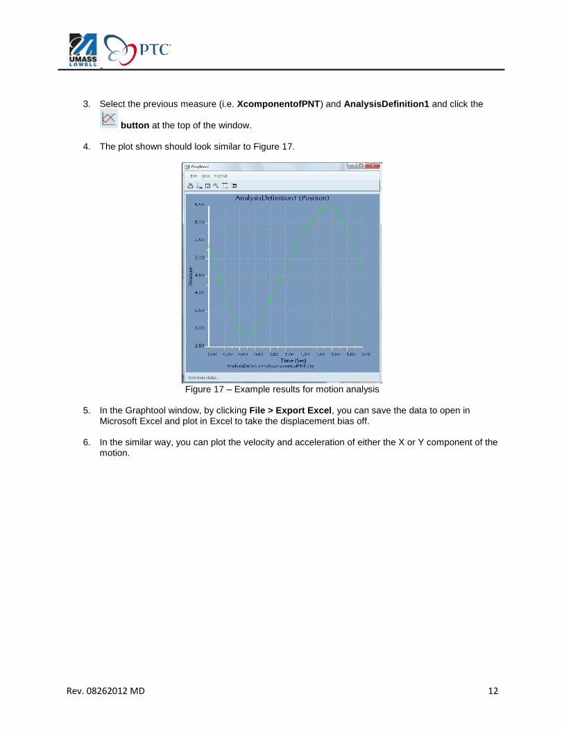
3. Select the previous measure (i.e. XcomponentofPNT) and AnalysisDefinition1 and click the
button at the top of the window.
4. The plot shown should look similar to Figure 17.
Figure 17 – Example results for motion analysis
5. In the Graphtool window, by clicking File > Export Excel, you can save the data to open in
Microsoft Excel and plot in Excel to take the displacement bias off.
6. In the similar way, you can plot the velocity and acceleration of either the X or Y component of the motion.


