CHAPTER 3 THE STRUCTURE OF CRYSTALLINE SOLIDS CRYSTALLINE SOLIDS.
Upload
coleen-ryanCategory
view
216download
0
T1 task- update
Mike Plissi

2
Motivation
Thermo-elastic noise is higher than the ‘intrinsic’ noise in crystalline materials
There are several sources of thermo-elastic noise including the dielectric mirror coatings and the silicate bonds used to attach the suspension fibres to the test masses
The mechanical losses associated with the mirror coatings is more relevant than was previously thought
Direct measurement of the thermal noise is necessary in order to compare with calculations
Study of time-series data will enable searches for excess impulsive events due to stress (e.g. in bonds)

3
Direct thermal noise measurements of thin membranes-INFN VIRGO
During the first year of activity a Fabry-Perot cavity has been realised with a finesse 30000, a bandwidth of 30kHz, and a displacement sensitivity of
The thermal noise of a 20 layer coating has been investigated (see below)
Hzm15103 −×
Frequency
22 / SiOTiO
Paolo Amico
4
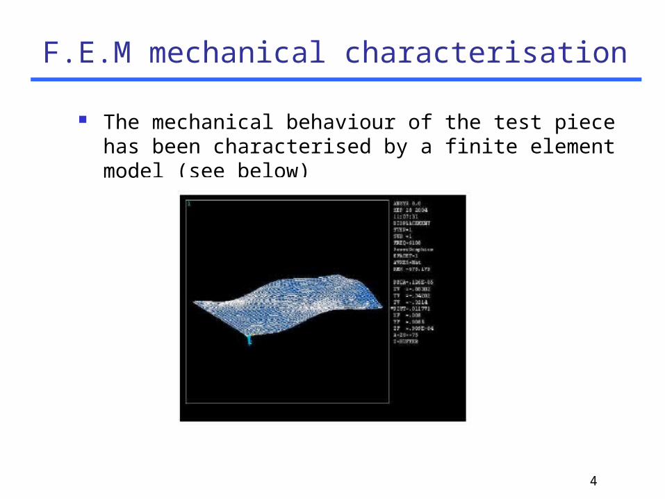
F.E.M mechanical characterisation
The mechanical behaviour of the test piece has been characterised by a finite element model (see below)

5
Sensitivity upgrade of the interferometric system in Perugia
Laser frequency stabilised to a Fabry-Perot reference cavity in order to reduce laser frequency noise
Preliminary frequency stabilisation has been realised with an aluminium cavity
Photo of the optical set-up

6
Improved sensitivity curve
Dis
pla
cem
en
t s
en
sit
ivit
y

7
Next steps
Next steps are to replace the temporary cavity with one made from Suprasil 3 and to reduce the electronic noise
Photo of the Suprasil 3 cavity that will replace the aluminium cavity

8
Direct thermal noise experiment- IGR Interferometric measurement technique
Goal: reduce other noise to well below thermal noiseTarget sensitivity is at 1kHz Hzm/103 20−×

9
Frequency stabilisation system
A Pound-Drever-Hall scheme is used
A three path feedback system is used for the frequency stabilisation: Feedback to PZT mounted on laser crystal Feedback to an EOM in the beam path Low frequency temperature feedback
A custom built servo has been constructed and currently performs close to the modelled transfer functions
10
Improvements to the laser frequency stabilisation
Performance was limited by losses in the optical set-up resulting in low intrinsic gain from the control system
Work has been done in improving both the optical and RF set-up
The light power into the interferometer has been increased and the mode-matching has been improved
The custom-built servo is now allowing feedback to all three paths and the gain of the EOM path is now much closer to the specification
Reference cavity now locks easily to the TEM-00 mode There is some phase delay at the higher frequencies
limiting the unity gain point to around 60 kHz

11
Reference cavity locking
Images taken from CCD camera positioned behind end mirror of the reference cavity showing locked state (right hand image)

12
Short cavity suspension rig
Double pendulum suspensions with enhanced vertical isolation
Monolithic suspension for each cavity mirror
short arm cavity
suspended reaction mass(used to apply feedback forces)

13
Fused silica fibre work
Photo of the new (LabVIEW controlled) fibre pulling machine
14
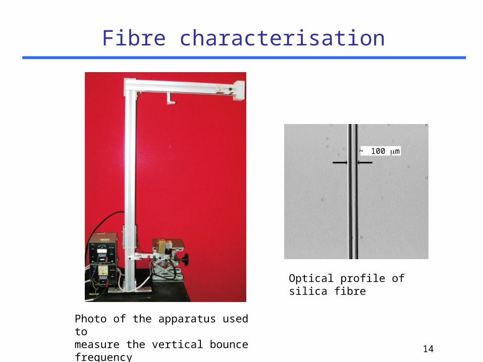
Fibre characterisation
Photo of the apparatus used to measure the vertical bounce frequency
~ 100 m
Optical profile of silica fibre
15
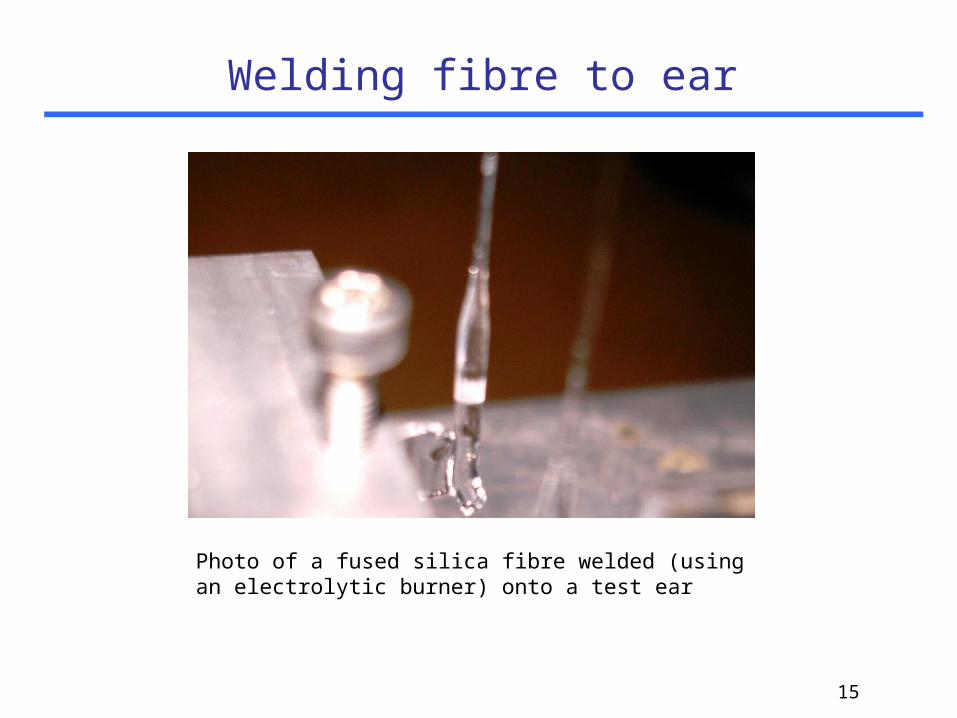
Welding fibre to ear
Photo of a fused silica fibre welded (using an electrolytic burner) onto a test ear

16
Pendulum suspension installation
Auxiliary optics have been installed Beam alignment of the auxiliary optics has been
completed Cantilever blades used for the vertical isolation of
the monolithic suspensions have been matched for deflection
The pick-off optics for the thermal noise cavity have been pre-adjusted on the optical bench
The electronics for controlling the reaction pendulum are currently being tested
17
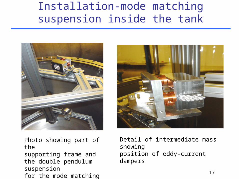
Installation-mode matching suspension inside the tank
Detail of intermediate mass showingposition of eddy-current dampers
Photo showing part of the supporting frame and the double pendulum suspension for the mode matching optic
18
Next steps
Install reaction pendulum Weld fibres to test masses (using purpose built jig)
Installation of short arm cavity
Locking of short arm cavity
Replacement of test mirror with a composite mass to investigate excess noise associated with a large bond area