T TM ENGINEERING - · PDF fileGEAR PUMP BASICS External Gear Pump Principle of Operation &...
67
TM LIQUIFLO CHEMICAL PROCESSING PUMPS tel. 908 . 518 . 0777 fax. 908 . 518 . 1847 www. liquiflo .com 86 ENGINEERING
Transcript of T TM ENGINEERING - · PDF fileGEAR PUMP BASICS External Gear Pump Principle of Operation &...

TM
T
L I Q U I F L O C H E M I C A L P R O C E S S I N G P U M P S
t e l . 9 0 8 . 5 1 8 . 0 7 7 7 f a x . 9 0 8 . 5 1 8 . 1 8 4 7 w w w . l i q u i f l o . c o m86
E N G I N E E R I N G
L I Q U I F L O C H E M I C A L P R O C E S S I N G P U M P S
E N G I N E E R I N G
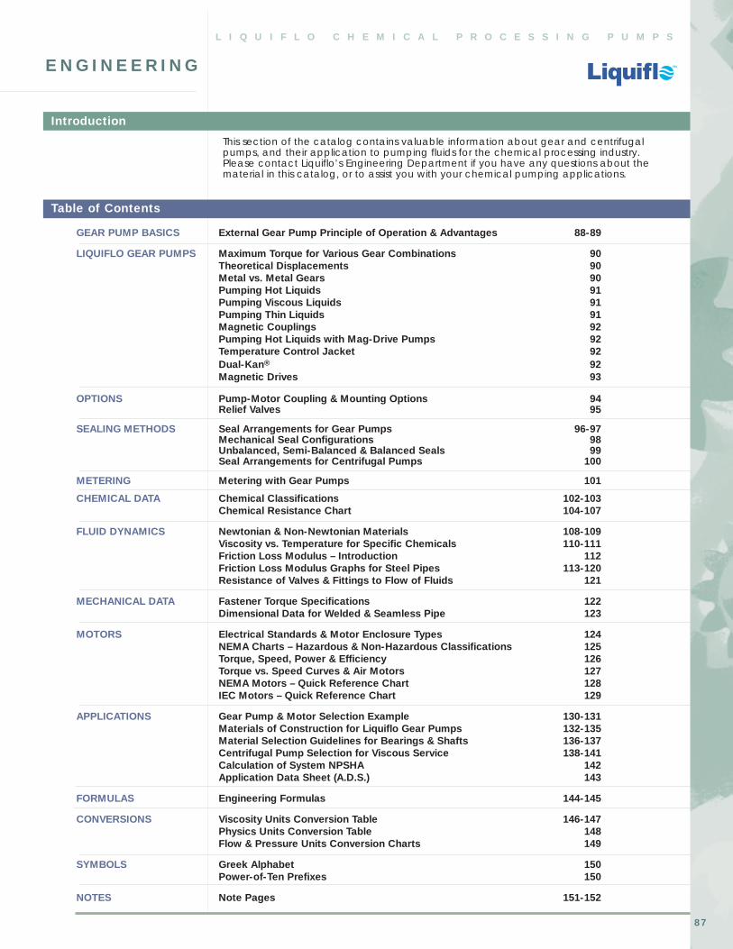
GEAR PUMP BASICS External Gear Pump Principle of Operation & Advantages 88-89
LIQUIFLO GEAR PUMPS Maximum Torque for Various Gear Combinations 90Theoretical Displacements 90Metal vs. Metal Gears 90Pumping Hot Liquids 91Pumping Viscous Liquids 91Pumping Thin Liquids 91Magnetic Couplings 92Pumping Hot Liquids with Mag-Drive Pumps 92Temperature Control Jacket 92Dual-Kan® 92Magnetic Drives 93
OPTIONS Pump-Motor Coupling & Mounting Options 94Relief Valves 95
SEALING METHODS Seal Arrangements for Gear Pumps 96-97Mechanical Seal Configurations 98 Unbalanced, Semi-Balanced & Balanced Seals 99Seal Arrangements for Centrifugal Pumps 100
METERING Metering with Gear Pumps 101
CHEMICAL DATA Chemical Classifications 102-103Chemical Resistance Chart 104-107
FLUID DYNAMICS Newtonian & Non-Newtonian Materials 108-109Viscosity vs. Temperature for Specific Chemicals 110-111Friction Loss Modulus – Introduction 112Friction Loss Modulus Graphs for Steel Pipes 113-120Resistance of Valves & Fittings to Flow of Fluids 121
MECHANICAL DATA Fastener Torque Specifications 122Dimensional Data for Welded & Seamless Pipe 123
MOTORS Electrical Standards & Motor Enclosure Types 124NEMA Charts – Hazardous & Non-Hazardous Classifications 125Torque, Speed, Power & Efficiency 126Torque vs. Speed Curves & Air Motors 127NEMA Motors – Quick Reference Chart 128IEC Motors – Quick Reference Chart 129
APPLICATIONS Gear Pump & Motor Selection Example 130-131Materials of Construction for Liquiflo Gear Pumps 132-135Material Selection Guidelines for Bearings & Shafts 136-137Centrifugal Pump Selection for Viscous Service 138-141Calculation of System NPSHA 142Application Data Sheet (A.D.S.) 143
FORMULAS Engineering Formulas 144-145
CONVERSIONS Viscosity Units Conversion Table 146-147Physics Units Conversion Table 148Flow & Pressure Units Conversion Charts 149
SYMBOLS Greek Alphabet 150Power-of-Ten Prefixes 150
NOTES Note Pages 151-152
This section of the catalog contains valuable information about gear and centrifugalpumps, and their application to pumping fluids for the chemical processing industry. Please contact Liquiflo’s Engineering Department if you have any questions about thematerial in this catalog, or to assist you with your chemical pumping applications.
Table of Contents
Introduction
TM
T
87

TM
T
88 t e l . 9 0 8 . 5 1 8 . 0 7 7 7 f a x . 9 0 8 . 5 1 8 . 1 8 4 7 w w w . l i q u i f l o . c o m
EXTERNAL GEAR PUMP PRINCIPLE OF OPERATION & ADVANTAGES
E N G I N E E R I N G - G e a r P u m p B a s i c s
The external gear pump is a positivedisplacement (PD) type of pumpgenerally used for the transfer andmetering of liquids. The pump is sonamed because it has two gears thatare side-by-side or external to eachother. (This nomenclature differen-tiates it from an internal gear pump,which has one gear positioned insidethe other.) The gear pump is aprecision machine with extremelytight fits and tolerances, and iscapable of working against highdifferential pressures.
The working principle of the externalgear pump is illustrated in Figure 1.A drive gear (that is driven by amotor) rotates an idler gear in theopposite direction. When the gearsrotate, the liquid, which is trapped inthe gear teeth spaces between thehousing bore and the outside of thegears, is transferred from the inlet sideof the pump to the outlet side. It isimportant to note that the pumpedliquid moves around the gears andnot between the gears. The rotatinggears continue to deliver a freshsupply of liquid from the suction (inlet)side of the pump to the discharge(outlet) side of the pump, withvirtually no pulsations. The meshing
INLET
DIRECTION OF FLOW
OUTLETINLET OUTLET
DRIVEGEAR
IDLERGEAR
HOUSING
Clockwise Rotationof Drive Gear
Counter-Clockwise Rotationof Drive Gear
IDLERSHAFT
DRIVESHAFT
of the gears on the discharge side of thepump forces the liquid out of the pumpand into the discharge piping.
Figure 1 also shows that the direction of rotation of the drive gear determinesthe direction of flow thru the pump, andwhich side of the pump is the inlet andwhich side is the outlet. If the directionof rotation of the motor (and thereforethe drive gear) is reversed, the directionof flow thru the pump will also reverse.This bi-directional flow characteristic isone of the many advantages inherentto gear pumps.
Another important advantage of thegear pump is its self-priming capability.Gear pumps are capable of self-primingbecause the rotating gears evacuate air in the suction line. This produces apartial vacuum that allows the atmos-pheric pressure to force the liquid intothe inlet side of the pump. This ability ofthe gear pump makes it an ideal choicewhen the application requires that thepump be located above the liquid level,and the liquid must be lifted to thepump. Because a gear pump cannotcreate a perfect vacuum, the total lift(including pipe friction losses) should notexceed about 7.5 PSI, or about one-halfof the atmospheric pressure.
The tight clearances of the working partsinside a gear pump are what enable it to effectively pump liquids against highpressure. Low viscosity fluids such asalcohols and other solvents have moreof a tendency to “slip” thru these tightspaces from the higher-pressuredischarge side of the pump back to thelower-pressure suction side of the pump.The phenomenon of slip causes a reduction in flow rate and pumpefficiency. Slip depends on themagnitude of the differential pressure(i.e., the difference between thedischarge and suction pressures), theviscosity of the liquid pumped and theworking clearances inside the particularpump that is used. Slip increases withdecreasing viscosity, increasingdifferential pressure and increasing gear-housing clearances, and is usuallymeasured as a percent decrease fromideal flow (i.e., flow with zero slip). Forfluid viscosities greater than about 50-100cP (depending on the particular pump),the slip is minor, but it still depends on thedifferential pressure. This behavior isshown in Figure 2, which compares atypical gear pump’s performance curvefor a thin fluid (such as water with aviscosity of about 1 cP at room temper-ature) with that of a moderately viscousfluid (such as a particular oil with aviscosity of 100 cP).
Figure 1: Cross-sectional views of external gear pump demonstrating operating principle.

TM
T
89t e l . 9 0 8 . 5 1 8 . 0 7 7 7 f a x . 9 0 8 . 5 1 8 . 1 8 4 7 w w w . l i q u i f l o . c o m
EXTERNAL GEAR PUMP PRINCIPLE OF OPERATION & ADVANTAGES (continued)
E N G I N E E R I N G - G e a r P u m p B a s i c s
The Flow vs. Pressure curves for the thinfluid have high slopes, which indicatesignificant reductions in flow rate withincreasing differential pressure (i.e., highslip). The curves for the 100 cP fluid arealmost level, which indicate nearlyconstant flow rates with increasingdifferential pressure (i.e., almost zero slip).
The close tolerances and tight spacesinside the gear pump also limit liquidscontaining abrasives from beingpumped. This is because the abrasiveparticles can work their way into thesetight spaces and cause acceleratedwear, and this can rapidly reduce pumpperformance. The resulting wear ratefrom pumping abrasives is dependentupon the hardness, size, and concen-tration of the particles, and the operat-ing speed of the pump. The wear rateof a pump can also be adverselyaffected by pumping thin fluids becausethey have poor lubricating properties.For this reason, more care must be takenwhen making material selections for theinternal components of the gear pump.Special materials are available toincrease lubrication (such as carbongraphite) and resist wear when pumpingextremely thin liquids or liquids contain-ing abrasives. Please contact thefactory to assist you with the materialselection process.
Gear pumps – properly designed andengineered – can offer many advantages.These include compactness, simplicity ofdesign, easy serviceability, bi-directionalflow capability, ability to self-prime,pulseless flow, low NPSHR (net positivesuction head required), high MTBM (mean time between maintenance), high-pressure and high-temperaturecapability, precise and accuratemetering, and availability in multiple sealconfigurations or sealless mag-drives.Liquiflo has over 35 years experience in designing and manufacturing qualityhigh-alloy gear pumps for the chemicalprocessing industry, and extensiveexperience in pumping acids, caustics,solvents, polymers and other types ofchemicals. Liquiflo’s experiencedengineers are available to assist you with your special chemical pumpingapplications.
10
9
8
7
6
5
4
3
2
1
0
DIFFERENTIAL PRESSURE (PSI)
10
9
8
7
6
5
4
3
2
1
080604020 1000
1750
1450
900
PO
WE
R(B
HP
)
FLO
W(G
PM
)
1750
DIFFERENTIAL PRESSURE (PSI)
80604020 1000
1750
1450
1150
900
PO
WE
R(B
HP
)
FLO
W(G
PM
)
600
1750
600
600
1.6
1.4
1.2
1.0
0.8
0.6
0.4
0.2
0
1150
1.6
1.4
1.2
1.0
0.8
0.6
0.4
0.2
0
0 2 4 6 8BAR
0 2 4 6 8BAR
LPM
36
32
28
24
20
16
12
8
4
0
LPM
36
32
28
24
20
16
12
8
4
0
600
1 cP Fluid (Water) 100 cP Fluid (Oil)
Figure 2: Performance curves for a typical external gear pump showing slip as a functionof viscosity and differential pressure.
TM
T
90 t e l . 9 0 8 . 5 1 8 . 0 7 7 7 f a x . 9 0 8 . 5 1 8 . 1 8 4 7 w w w . l i q u i f l o . c o m
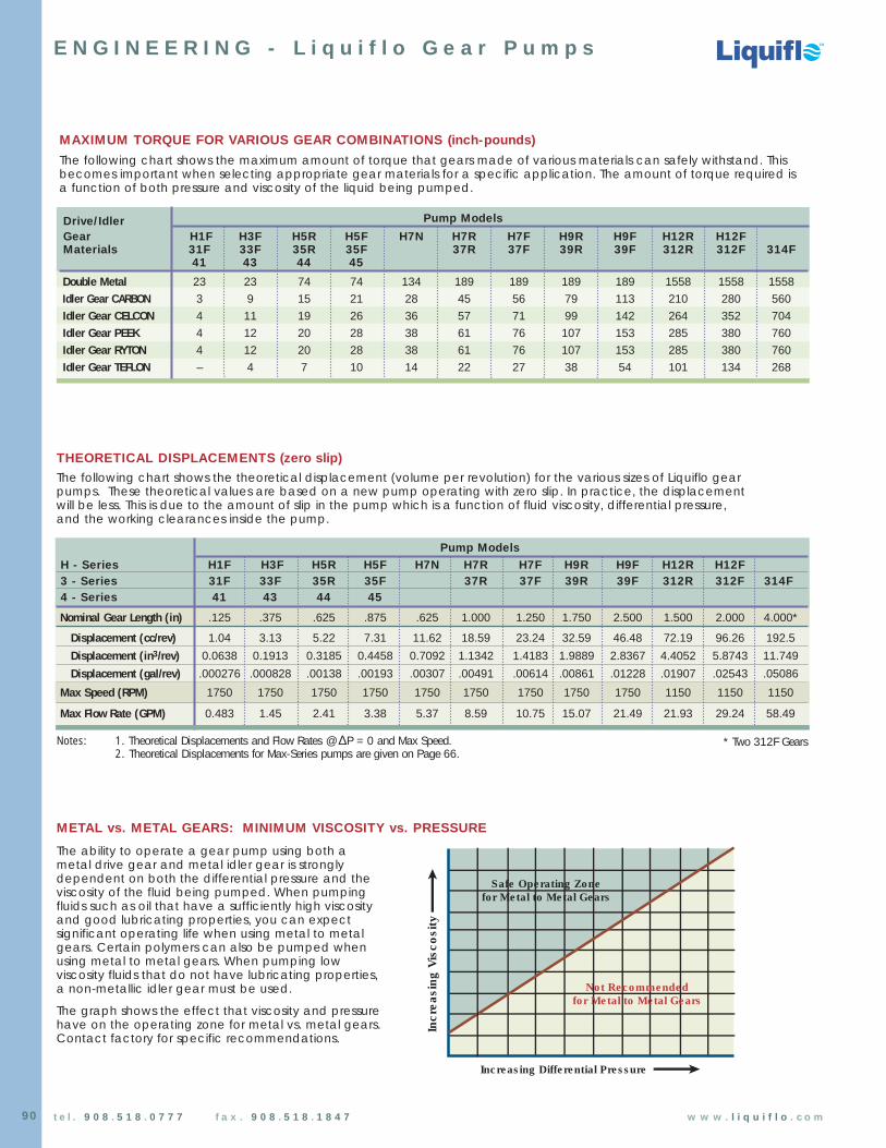
THEORETICAL DISPLACEMENTS (zero slip)
E N G I N E E R I N G - L i q u i f l o G e a r P u m p s
Drive/Idler Pump Models
Gear H1F H3F H5R H5F H7N H7R H7F H9R H9F H12R H12FMaterials 31F 33F 35R 35F 37R 37F 39R 39F 312R 312F 314F
41 43 44 45
Double Metal 23 23 74 74 134 189 189 189 189 1558 1558 1558Idler Gear CARBON 3 9 15 21 28 45 56 79 113 210 280 560Idler Gear CELCON 4 11 19 26 36 57 71 99 142 264 352 704Idler Gear PEEK 4 12 20 28 38 61 76 107 153 285 380 760Idler Gear RYTON 4 12 20 28 38 61 76 107 153 285 380 760Idler Gear TEFLON – 4 7 10 14 22 27 38 54 101 134 268
Pump Models
H - Series H1F H3F H5R H5F H7N H7R H7F H9R H9F H12R H12F3 - Series 31F 33F 35R 35F 37R 37F 39R 39F 312R 312F 314F 4 - Series 41 43 44 45
Nominal Gear Length (in) .125 .375 .625 .875 .625 1.000 1.250 1.750 2.500 1.500 2.000 4.000*
Displacement (cc/rev) 1.04 3.13 5.22 7.31 11.62 18.59 23.24 32.59 46.48 72.19 96.26 192.5
Displacement (in3/rev) 0.0638 0.1913 0.3185 0.4458 0.7092 1.1342 1.4183 1.9889 2.8367 4.4052 5.8743 11.749
Displacement (gal/rev) .000276 .000828 .00138 .00193 .00307 .00491 .00614 .00861 .01228 .01907 .02543 .05086
Max Speed (RPM) 1750 1750 1750 1750 1750 1750 1750 1750 1750 1150 1150 1150
Max Flow Rate (GPM) 0.483 1.45 2.41 3.38 5.37 8.59 10.75 15.07 21.49 21.93 29.24 58.49
* Two 312F Gears
Increasing Differential Pressure
Incr
easi
ngV
isco
sity
900
8
Safe Operating Zonefor Metal to Metal Gears
Not Recommended for Metal to Metal Gears
METAL vs. METAL GEARS: MINIMUM VISCOSITY vs. PRESSURE
The ability to operate a gear pump using both ametal drive gear and metal idler gear is stronglydependent on both the differential pressure and theviscosity of the fluid being pumped. When pumpingfluids such as oil that have a sufficiently high viscosityand good lubricating properties, you can expectsignificant operating life when using metal to metalgears. Certain polymers can also be pumped whenusing metal to metal gears. When pumping lowviscosity fluids that do not have lubricating properties,a non-metallic idler gear must be used.
The graph shows the effect that viscosity and pressurehave on the operating zone for metal vs. metal gears.Contact factory for specific recommendations.
The following chart shows the theoretical displacement (volume per revolution) for the various sizes of Liquiflo gearpumps. These theoretical values are based on a new pump operating with zero slip. In practice, the displacementwill be less. This is due to the amount of slip in the pump which is a function of fluid viscosity, differential pressure,and the working clearances inside the pump.
MAXIMUM TORQUE FOR VARIOUS GEAR COMBINATIONS (inch-pounds)
The following chart shows the maximum amount of torque that gears made of various materials can safely withstand. Thisbecomes important when selecting appropriate gear materials for a specific application. The amount of torque required is a function of both pressure and viscosity of the liquid being pumped.
Notes: 1. Theoretical Displacements and Flow Rates @ ∆P = 0 and Max Speed.2. Theoretical Displacements for Max-Series pumps are given on Page 66.

TM
T
91t e l . 9 0 8 . 5 1 8 . 0 7 7 7 f a x . 9 0 8 . 5 1 8 . 1 8 4 7 w w w . l i q u i f l o . c o m
E N G I N E E R I N G - L i q u i f l o G e a r P u m p s
PUMPING HOT LIQUIDSHot liquids affect expansions in the pump and (most often) have lower viscosities as compared to cooler temperatures.Gear pumps with seals are limited to about 500 ˚F (260 ˚C) and the range of internal materials at this temperature level islimited to metallic or carbon gears, carbon or SiC wear plates, bearings and seal faces, and graphoil wedges or packingin the seals. At lower temperatures, a number of alternate materials can be used as shown in the Maximum UseTemperatures chart below.
Liquiflo’s pump specification procedure analyzes the temperature conditions and determines what effects, if any, are relevant. Plastic gears are trimmed in length and diameter to accommodate thermal expansion. Under certaincircumstances bearings will be trimmed as well.
PUMPING VISCOUS LIQUIDSGear pumps excel at pumping moderately viscous and viscous liquids. Horsepower shown on Liquiflo's performance curves are based on the application’s brake horsepower (BHP). The power requirements for viscous liquids can besignificantly reduced (by as much as sixty percent) by trimming the gears (to increase clearances which reduce drag) and by lowering the RPM. By selecting a larger pump and running it slower, the savings in power consumption can outweigh the additional cost of the larger pump. In addition, operating a larger pump at a slower speed will increase the life span of the pump.
PUMPING THIN LIQUIDSFrequently, gear pumps are the preferred solution to low-viscosity pumping applications because of their hydraulics (low flow, high pressure and pulseless flow), compactness, efficiency and low cost. However, thin fluids affect gear pump wear characteristics and slip. These considerations are addressed in Liquiflo's pump designs. Viscosities as low as 0.3 CPShave been satisfactorily pumped.
Thin liquids prevent hydrodynamic film formation. For gear pumps, this means that the bearing-to-shaft or gear-to-gearinterfaces may have poor lubrication causing accelerated wear. Liquiflo has reduced the problems associated with thinfluids for many applications by providing parts specifically designed to minimize the types of wear associated with poor filmlubrication. Tungsten Carbide shafts, Silicon Carbide bearings and specially designed front and rear housings, made toenhance journal bearing lubrication, are all significant aids.
Slip is also a factor when pumping thin fluids with gear pumps. Slip is a function of viscosity, differential pressure, and thespecific pump design. In order to generate the specified flow at a given differential pressure, thin liquids require a higherRPM than viscous liquids.
MAX USE TEMPERATURES (˚F) FOR NON-METALLIC COMPONENTS IN GEAR PUMPS
WEAR COATED O-RING/ SEAL SEAL WEDGE/MATERIALS GEAR PLATE BEARING SHAFT GASKET FACE PACKING
Teflon 230 260 180 NA 500 180 350
Ryton 300 350 250 NA NA NA NA
PEEK 400 450 350 NA NA NA NA
Carbon 500 500 500 NA NA 500 NA
Silicon Carbide (SiC) NA 500 500 NA NA 500 NA
Graphoil NA NA NA NA 500 NA 500
Chrome Oxide (CO) NA NA NA 250 NA NA NA
Tungsten Carbide (TC) NA NA NA 500 NA NA NA
TM
T
92 t e l . 9 0 8 . 5 1 8 . 0 7 7 7 f a x . 9 0 8 . 5 1 8 . 1 8 4 7 w w w . l i q u i f l o . c o m
E N G I N E E R I N G - L i q u i f l o G e a r P u m p s
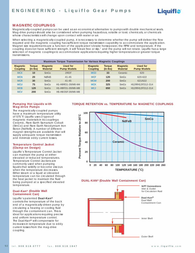
TORQUE RETENTION vs. TEMPERATURE for MAGNETIC COUPLINGS
0 20 40 60 80 100 120 140 160 180 200 220 240 260
100
80
60
40
20
0
TEMPERATURE (˚C)
Per
cen
tTo
rqu
eR
elat
ive
to20
˚C
NdFeBSmCo
Ceramic
MAGNETIC COUPLINGSMagnetically-coupled pumps can be used as an economical alternative to pumps with double mechanical seals.Mag-drive pumps should also be considered when pumping hazardous, volatile or toxic chemicals, or chemicalswhose characteristics will change upon contact with water or air.
When selecting a magnetically-coupled pump, it is necessary to determine whether the pump will deliver the flowrequired and the magnetic coupling has sufficient torque transmission capability to accommodate the application.Magnet size requirements are a function of the application’s brake horsepower, the RPM and temperature. If thecoupling does not have sufficient strength, it will "break free or slip,” and the pump will not rotate. Liquiflo has a largeselection of magnetic couplings to accommodate applications requiring higher temperatures or greater torquetransmissions.
Maximum Torque Transmission for Various Magnetic Couplings
Magnetic Torque Magnetic Used for Magnetic Torque Magnetic Used forCoupling (in-lbs) Material Pump Models Coupling (in-lbs) Material Pump Models
MCX 10 SmCo 2R/2F MCD 33 Ceramic 620
MCN 20 NdFeB 41-45 MCF 120 SmCo 620-622MCR 30 SmCo 41-45 MCW 200 SmCo 621/622MCU 75 SmCo H1-H9R/31-39/M0-M4 MCK 325 SmCo H12R/H12F/312-314MCB 120 SmCo H1-H9F/31-39/M0-M8 MCJ 650 SmCo H12R/H12F/312-314MCV 200 SmCo H5-H9/35F-39/M0-M8
Pumping Hot Liquids withMag-drive PumpsThe magnetically-coupled pumpshave a maximum temperature utility of 575 ˚F. Liquiflo uses 3 types ofmagnetic materials in its couplings:Ceramic, Rare Earth Samarium Cobalt(SmCo) and Rare Earth Neodymium IronBoron (NdFeB). A number of differentmagnet strengths are available that willsupply adequate torque transmissionand minimize eddy current losses.
Temperature Control Jacket(Clamp-on Design)Liquiflo’s Temperature Control Jacketcan maintain the pump at eitherelevated or reduced temperatures.Temperature Control Jackets arecommonly used when pumping liquids that solidify or become viscous when the temperature decreases. Either steam or a liquid at elevatedtemperature can be circulated throughthe heat jacket to maintain the fluidbeing pumped at a specified elevatedtemperature.
Dual-Kan® (Double WallContainment Can)Liquiflo’s patented Dual-Kan®
controls the temperature of the backend of a magnetically-driven pump bycirculating a heating or cooling fluidthrough the containment can. This isideal for applications requiring preciseand uniform temperature control. The Dual-Kan® will compensate forincreases in temperature due to eddycurrent losses from the mag-drivecoupling.
Dual-Kan®Dual WallContainment Can
NPT ConnectionsInlet & Outlet for Circulation Fluid
Inner Shell
Outer Shell
DUAL-KAN® (Double Wall Containment Can)

TM
T
93t e l . 9 0 8 . 5 1 8 . 0 7 7 7 f a x . 9 0 8 . 5 1 8 . 1 8 4 7 w w w . l i q u i f l o . c o m
E N G I N E E R I N G - L i q u i f l o G e a r P u m p s
MAG-DRIVE PUMP, CLOSE-COUPLED
The 4 Golden Rules of Magnetic Drives
1 Power losses are directly proportional to the square of the speed (n).2 Power losses are directly proportional to the square of the drive radius (r).3 Power losses are directly proportional to the square of the flux density (B).4 Power losses are inversely proportional to the resistivity (ρρ) of the barrier material.
MAGNETIC DRIVESThe most important advantage of the permanent magnet drive is that it makes possible the transmission of torque through a barrier without the use of any mechanical connection. Because these drive couplings are entirely magnetic, this completely eliminates seals, along with their associated leakage, maintenance and contamination problems. The type of magnetic drive used in Liquiflo pumps are referred to as synchronous because the inner and outer magnets rotate at the exact same speed.
Radial type synchronous drives (which are the type used for Liquiflo Pumps) consist of an inner and outer magnet assembly magnetized with multiple poles about their respective inside and outside diameters. The radial type drive has no axial component of thrust but does require tight tolerance to minimize the radial gap between the inner and outerrotating members. When the maximum torque of a synchronous drive is exceeded, the follower, or driven member, will fall out of step and stop rotating. The load cannot be picked up again unless the driving member (the outer magnet which is connected to the motor), is first stopped and then restarted. This can be an important and useful feature if an over-pressure condition occurs in a system.
The containment shell for mag-drives pumps can be made from a conducting material; however, it is usually non-magnetic. Eddy current losses will occur if the containment shell is conductive and these losses are inverselyproportional to the resistivity of the barrier shell.
Typical design requirements that are considered with permanent magnet drives are:
(A) maximum torque to be transmitted
(B) speed at which the torque is to be transmitted
(C) the gap and material through which the torque is to be transmitted
(D) the temperature at which the unit will operate
(E) any physical size limitations of the coupling
Outer MagnetAssembly
Containment Can
Outer Magnets
Inner Magnets
Inner MagnetAssembly
PUMP
MOTOR
PLossesn2 r2 B2
ρρ

Chemical Processing Pumps
Chemical Processing Pumps
TM
TM
TM
94 t e l . 9 0 8 . 5 1 8 . 0 7 7 7 f a x . 9 0 8 . 5 1 8 . 1 8 4 7 w w w . l i q u i f l o . c o m
PUMP-MOTOR COUPLING & MOUNTING OPTIONS
E N G I N E E R I N G - O p t i o n s
Pedestal/Power FrameThis is the standard pedestal used for long-coupling the Liquiflo Centry-Series Centrifugal Pumps. The Liquiflo Power Frame is also usedfor long-coupling the Liquiflo H-Series and 3-Series Gear Pumps.
High-Temperature Applications:
A key feature of the Liquiflo PowerFrame is its integral cooling jacketwhich keeps the bearing system of the pedestal cool even when it iscoupled to a pump operating atextremely high temperature.
Base Mounted PumpDimensions and nomenclatureconform to Hydraulic Institute (HI)standards. Bases are made fromstainless steel or from steelchannel painted for corrosionresistance. These units can beassembled at the factory. Thiseliminates having to mount unitsin the field which may be difficultor inconvenient without properalignment instrumentation.
Coupling safety guards areavailable to help protectpersonnel from the rotatingelements of the pump and motor.
S-AdapterThe Liquiflo S-Adapter is used inconjunction with the MC-Pedestal Bracket for long-coupling mag-drivepumps. It is also used when long-coupling pumps to motors or drives that do not have a C-face mounting.Typical examples are air motors, gearreducers, or specialty motors that are not available with C-face mounting.
The temperature rating of the S-Adapter is 250˚F (~120˚C).
Coupling SafetyGuard
RiserBlock
MOTOR
Coupling
CoolingJacket
OilFuelPlug
Oil DrainPlug
CoolingJacket
Connection
CoolingJacket
Connection
X
X
Z
CP
HC
C
HF
HB
HP HE
HA
HE
HT HL
HD

Chemical Processing Pumps
Chemical Processing Pumps
TM
TM
TM
95t e l . 9 0 8 . 5 1 8 . 0 7 7 7 f a x . 9 0 8 . 5 1 8 . 1 8 4 7 w w w . l i q u i f l o . c o m
RELIEF VALVES
E N G I N E E R I N G - O p t i o n s
10 ft.
2 ft.
Supply Tank
Supply Tank
1 ft.
5 ft.
Tee Pipe Connection(for priming)
3 ft.
226 ft.
3 ft.
36 ft.
2 ft.
Supply Tank
Relief Valve
4 ft.
3 ft.
FLOW
Protection of Pump from Over-Pressure ConditionPositive Displacement Rotary Pumps should always be installed with a Relief Valve in the discharge line, to protect the pump and piping against any type of line blockage, including the inadvertant closing of an isolation valve.
Liquiflo manufactures two sizes of Relief Valves in 316 SS and Alloy-C. Ten standard Relief Valve models are availabledepending on the body material, the port size and the discharge pressure range (see table below).
Adjusting CapAdjusts discharge pressure ofRelief Valve. Adjustment can beperformed while the Relief Valveis in service without leakage.
SpringAvailable in 316 SSor Alloy-C
Safety Lock PinEnsures parts will not separateeven if Adjusting Capis removed.
Lock NutLocks Adjusting Cap in place.
Teflon O-RingGives Liquiflo Relief Valve aunique advantage by allowingadjustment without leakagewhile in service.
Inlet1/2” or 1” NPT
Body Available in 316 SS or Alloy-C
Outlet1/2” or 1” NPT
PROPER HOOK-UP OF PUMP WITH SEPARATE RELIEF VALVERELIEF VALVE CROSS-SECTION
Proper configuration with Relief Valve directly bypassing thedischarge line back to the supply tank.
Gear Pump(or otherPD pump)
ReliefValve
Supply Tank
Liquiflo Standard Relief Valves
Port SizePressure Setting Approximate Flow at 25%
Model # Material & Type(PSI) above Pressure Setting
Min Max GPM LPMRV1000-LP 316 SS 1/2” NPT 25 65 7.5 28RV1000 316 SS 1/2” NPT 50 135 7.5 28RV1000-HP 316 SS 1/2” NPT 75 200 7.5 28RV1001-LP Alloy-C 1/2” NPT 25 65 7.5 28RV1001 Alloy-C 1/2” NPT 50 135 7.5 28RV1001-HP Alloy-C 1/2” NPT 75 200 7.5 28
RV2000-LP 316 SS 1” NPT 25 75 25 95RV2000 316 SS 1” NPT 50 175 25 95
RV2001-LP Alloy-C 1” NPT 25 75 25 95RV2001 Alloy-C 1” NPT 50 175 25 95

Chemical Processing Pumps
Chemical Processing Pumps
TM
TM
TM
96 t e l . 9 0 8 . 5 1 8 . 0 7 7 7 f a x . 9 0 8 . 5 1 8 . 1 8 4 7 w w w . l i q u i f l o . c o m
SEAL ARRANGEMENTS FOR GEAR PUMPS
E N G I N E E R I N G - S e a l i n g M e t h o d s
Single Mechanical Seal - Internally Mounted Single Mechanical Seal - Externally Mounted
4
3
5
1 Seal Wedge
2 Rotating Seal Face
3 Stationary Seal Seat
4 Gaskets for Seal Seat
5 Mechanical Seal Body
Single Internal Mechanical SealThe Single Mechanical Seal arrangement is the standardand is by far the most commonly used when pumping anytype of chemical where leakage needs to be kept to aminimum. This seal type can tolerate limited amounts ofabrasive particles. The maximum fluid viscosityrecommended is 5000 CPS.
Single External Mechanical SealThe External Mechanical Seal arrangement is used whensystem pressures are below atmospheric pressure (vacuum).This is because the atmospheric pressure will assist in holdingthe seal faces together. This seal arrangement isolates themechanical seal from the fluid being pumped which can be an advantage when pumping chemicals that are notcompatible with the seal body. The maximum fluid viscosityrecommended is 5000 CPS.
12
4
1
5
2
3
1 Seal Wedge
2 Rotating Seal Face
3 Stationary Seal Seat
4 Gaskets for Seal Seat
5 Mechanical Seal Body
Seal Materials Available
PACKING SEAL WEDGES SEAL FACES SEAL SEATS
Braided Teflon Teflon Carbon Silicon Carbide• Extremely chemically • Extremely chemically • Resistant to majority • Extremely chemically
resistant – resistant – of chemicals – resistant – primary choice primary choice primary choice primary choice
• High abrasion resistanceGraphoil Graphoil Teflon• For high temperature • For high temperature • Extremely chemically
use – over 350 ˚F up use – over 350 ˚F up resistant to 500 ˚F to 500 ˚F • Pressure limited to 50 PSI
• Not abrasive resistant
Silicon Carbide• Extremely chemically
resistant• High abrasion resistance
Chemical Processing Pumps
Chemical Processing Pumps
TM
TM
TM
97t e l . 9 0 8 . 5 1 8 . 0 7 7 7 f a x . 9 0 8 . 5 1 8 . 1 8 4 7 w w w . l i q u i f l o . c o m
3
SEAL ARRANGEMENTS FOR GEAR PUMPS (continued)
E N G I N E E R I N G - S e a l i n g M e t h o d s
Double Mechanical Seal Packing
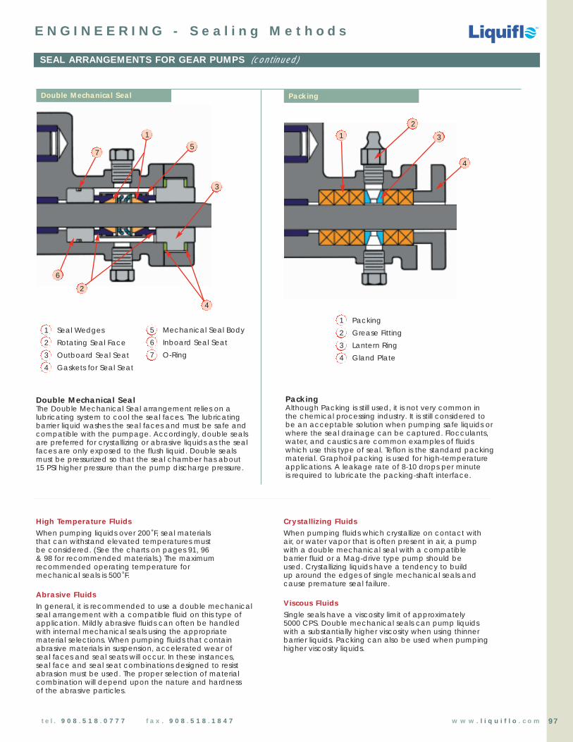
Double Mechanical SealThe Double Mechanical Seal arrangement relies on alubricating system to cool the seal faces. The lubricatingbarrier liquid washes the seal faces and must be safe andcompatible with the pumpage. Accordingly, double sealsare preferred for crystallizing or abrasive liquids as the sealfaces are only exposed to the flush liquid. Double sealsmust be pressurized so that the seal chamber has about 15 PSI higher pressure than the pump discharge pressure.
PackingAlthough Packing is still used, it is not very common in the chemical processing industry. It is still considered to be an acceptable solution when pumping safe liquids orwhere the seal drainage can be captured. Flocculants,water, and caustics are common examples of fluids which use this type of seal. Teflon is the standard packingmaterial. Graphoil packing is used for high-temperatureapplications. A leakage rate of 8-10 drops per minute is required to lubricate the packing-shaft interface.
High Temperature FluidsWhen pumping liquids over 200 ˚F, seal materialsthat can withstand elevated temperatures must be considered. (See the charts on pages 91, 96 & 98 for recommended materials.) The maximumrecommended operating temperature for mechanical seals is 500 ˚F.
Abrasive FluidsIn general, it is recommended to use a double mechanicalseal arrangement with a compatible fluid on this type ofapplication. Mildly abrasive fluids can often be handledwith internal mechanical seals using the appropriatematerial selections. When pumping fluids that containabrasive materials in suspension, accelerated wear of seal faces and seal seats will occur. In these instances,seal face and seal seat combinations designed to resistabrasion must be used. The proper selection of materialcombination will depend upon the nature and hardness of the abrasive particles.
Crystallizing FluidsWhen pumping fluids which crystallize on contact with air, or water vapor that is often present in air, a pump with a double mechanical seal with a compatible barrier fluid or a Mag-drive type pump should be used. Crystallizing liquids have a tendency to build up around the edges of single mechanical seals andcause premature seal failure.
Viscous FluidsSingle seals have a viscosity limit of approximately 5000 CPS. Double mechanical seals can pump liquids with a substantially higher viscosity when using thinnerbarrier liquids. Packing can also be used when pumpinghigher viscosity liquids.
4
3
2
5
1
1 Seal Wedges
2 Rotating Seal Face
3 Outboard Seal Seat
4 Gaskets for Seal Seat
6
7
1 Packing
2 Grease Fitting
3 Lantern Ring
4 Gland Plate
4
1
2
5 Mechanical Seal Body
6 Inboard Seal Seat
7 O-Ring
Chemical Processing Pumps
Chemical Processing Pumps
TM
TM
TM
98 t e l . 9 0 8 . 5 1 8 . 0 7 7 7 f a x . 9 0 8 . 5 1 8 . 1 8 4 7 w w w . l i q u i f l o . c o m
MECHANICAL SEAL CONFIGURATIONS
E N G I N E E R I N G - S e a l i n g M e t h o d s
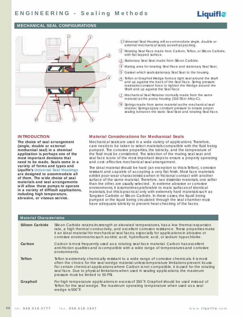
1 Universal Seal Housing will accommodate single, double orexternal mechanical seals, as well as packing.
2 Rotating Seal Face made from Carbon, Teflon, or Silicon Carbide,with flat lapped surface.
3 Stationary Seal Seat made from Silicon Carbide.
4 Mating area for rotating Seal Face and stationary Seal Seat.
5 Gasket which seals stationary Seal Seat to the housing.
6 Teflon or Graphoil Wedge forms a tight seal around the shaft and up against the back of the Seal Face. Spring pressure maintains constant force to tighten the Wedge around the Shaft and up against the Seal Face.
7 Mechanical Seal Retainer normally made from the same material as the pump housing (316 SS or Alloy-C).
8 Springs made from same material as the mechanical seal retainer. Springs apply constant pressure to ensure proper sealing between the static Seal Seat and rotating Seal Face.
2
3
5678
4
INTRODUCTIONThe choice of seal arrangement(single, double or externalmechanical seal) in a chemicalapplication is perhaps one of themost important decisions that need to be made. Seals come in avariety of forms and types andLiquiflo's Universal Seal Housingsare designed to accommodate all of them. The wide choice of sealmaterials and seal arrangementswill allow these pumps to operatein a variety of difficult applications,including high temperature,abrasive, or viscous service.
Material Considerations for Mechanical SealsMechanical seals are used in a wide variety of applications. Therefore, care needs to be taken to select materials compatible with the fluid beingpumped. The corrosive properties, the lubricity, and the temperature ofthe fluid must be considered. The selection of the mating seal seat andseal face is one of the most important steps to ensure a properly operatingand cost- effective mechanical seal arrangement.
The ideal material should be hard (an exception to this is Teflon), corrosionresistant and capable of accepting a very flat finish. Most face materialsexhibit poor wear characteristics when in frictional contact with anothersurface of the same material. Therefore, two dissimilar materials, one softerthan the other, are usually selected. In extreme abrasive or corrosiveenvironments, it is sometimes preferable to mate surfaces of identicalmaterials, but this is practical only with extremely hard materials such asTungsten Carbide or Silicon Carbide. In these cases, the liquid beingpumped or the liquid being circulated through the seal chamber musthave adequate lubricity to prevent heat-checking of the faces.
Silicon Carbide Silicon Carbide retains its strength at elevated temperatures, has a low thermal expansion rate, a high thermal conductivity, and excellent corrosion resistance. These properties make it an ideal material for mechanical seal faces, especially for applications in abrasive or corrosive environments such as nitric acid, hydrofluoric acid, or sodium hypochlorite.
Carbon Carbon is most frequently used as a rotating seal face material. Carbon has excellent anti-friction qualities and is compatible with a wide range of temperatures and corrosive environments.
Teflon Teflon is extremely chemically resistant to a wide range of corrosive chemicals. It is most often the choice for the seal wedge material unless temperature limitations prevent its use. For certain chemical applications where Carbon is not compatible, it is used for the rotating seal face. Due to physical limitations when used in sealing applications, the maximum pressure must be limited to 50 PSI.
Graphoil For high temperature applications in excess of 350 ˚F, Graphoil should be used instead of Teflon for the seal wedge. The maximum operating temperature when used as a seal wedge is 500 ˚F.
Material Characteristics
1

Chemical Processing Pumps
Chemical Processing Pumps
TM
TM
TM
99t e l . 9 0 8 . 5 1 8 . 0 7 7 7 f a x . 9 0 8 . 5 1 8 . 1 8 4 7 w w w . l i q u i f l o . c o m
UNBALANCED, SEMI-BALANCED & BALANCED SEALS
E N G I N E E R I N G - S e a l i n g M e t h o d s
HydraulicPressure
HydraulicPressure
HydraulicPressure
UNBALANCED SEAL
SEMI-BALANCED SEAL
BALANCED SEAL
Unbalanced SealWhen unbalanced seals are mountedinternally to the pump, the System Pressureassists the seal springs in keeping the sealfaces closed. This is the most common sealconfiguration for Liquiflo gear and centrifugalpumps. Unbalanced seals can be used forpressures as high as 350 PSI; however, thisdepends on the type and nature of the fluidbeing pumped. When unbalanced seals aremounted externally to the pump, the SystemPressure will have a tendency to open the seal faces.
O-Rings Rotating Stationary ShaftSeal Face Seal Seat
Semi-Balanced SealSemi-balanced seals require a step shaft.They reduce the loading on the sealface/seal seat mating area, allowing higherSystem Pressure without exceeding the PVlimit of the seal face combination.Cartridge style seals are available thatincorporate a semi-balanced design.
Balanced SealWith fully-balanced seals, the springpressure of the seal is the only force thatholds the seal faces together. Fully-balanced seals are used in situations with extremely high System Pressure.
Unbalanced, Semi-Balanced & Balanced SealsLiquiflo normally uses unbalanced seals which are considered acceptable up to pressures of 350 PSI. Whenhigher pressures or difficult applications that contain abrasives are encountered, it may be required to use semi-balanced or balanced seal configurations. These serve to reduce frictional forces in the mating area of the seal.
Mating Area
Mating Area
Mating Area
Rotating Seal Face Stationary Seal Seat
Rotating StationarySeal Face Seal Seat
Rotating Seal Face Stationary Seal Seat

Chemical Processing Pumps
Chemical Processing Pumps
TM
TM
TM
100 t e l . 9 0 8 . 5 1 8 . 0 7 7 7 f a x . 9 0 8 . 5 1 8 . 1 8 4 7 w w w . l i q u i f l o . c o m
SEAL ARRANGEMENTS FOR CENTRIFUGAL PUMPS
E N G I N E E R I N G - S e a l i n g M e t h o d s
Single Seal – Internally Mounted
Single Seal – Externally MountedSingle Seal, External An externally mounted mechanical seal requirescooling and lubrication flow through the sealchamber. This is accomplished with a seal flushline, generally from the high-pressure side to thelow-pressure side of the pump, introduced to theseal chamber as close to the sealing faces aspractical. An externally mounted seal does nothave the same reliability of a single internallymounted seal because the pump pressure is working against it.
Single Seal, Internal Cooling and lubrication of a single inside-mounted mechanical seal is provided by pipingfrom the discharge or high-pressure side of thepump to the seal chamber. This arrangement isan excellent choice because the liquid passingthrough the equipment can provide propercooling and lubrication for the mechanical seal. A seal in this position automatically utilizes thepumping pressure to help it accomplish its sealingjob. Consequently, it has the best reliability factorbecause the seal is cooled and lubricated whenthe equipment is in operation.
Double Seal ArrangementDouble Seal ArrangementThis is the most popular type of multiple sealarrangement. Two seals oriented back-to-backprovide a closed area in which a proper seallubricant and coolant is circulated at a pressuregenerally 5 to 20 psi above the pressure at thethroat of the seal chamber. The barrier liquid iscooled by an external source.
Pumped Fluid
Stationary Seal Seat
Seal Wedge
Rotating Seal Face
Pump Shaft
Pumped Fluid
Stationary Seal Seat
Seal Wedge
Rotating Seal Face
Pump Shaft
Barrier Fluid
Stationary Seal Seat
Seal Wedge
Rotating Seal Face
Pump ShaftPumped Fluid

Chemical Processing Pumps
Chemical Processing Pumps
TM
TM
TM
101t e l . 9 0 8 . 5 1 8 . 0 7 7 7 f a x . 9 0 8 . 5 1 8 . 1 8 4 7 w w w . l i q u i f l o . c o m
Flow Meter
VariableSpeedMotor
MotorController
Gear Pump
VariableSpeedMotor
MotorController
Process Tank
pHSensor
Gear Pump
Process Tank
Supply Tank
Supply Tank
METERING WITH GEAR PUMPS
E N G I N E E R I N G - M e t e r i n g
The numerous advantages of using gearpumps have made them a popular pumptype when flows need to be metered ortotalized. These advantages over other types of pumps are:
Virtually no pulsationsThis allows flows to be easily and accuratelymeasured with standard flow meters. Pipediameters can be much smaller in relation to those used with pulsing diaphragm pumpswhose pipe diameters are based on highinstantaneous flow rates.
Lower NPSH requirementsGear pumps require less NPSH because of their steady non-pulsating flow charac-teristics. Diaphragm or piston style pumpsrequire higher NPSH because of their highinstantaneous flow rates. NPSHA decreasesfurther as the viscosity of the fluid increases.
Simplicity of designGear pumps are extremely simple to understandand maintain. There are no check valves thatcan become clogged or fail, and pulsationdampeners are not required.
Sealless designMag-drive gear pumps eliminate the leakageassociated with mechanically sealed pumps.There are no diaphragms to rupture allowingprocess fluid to leak or destroy the pump, orgear box lubrication oil to enter the process.
High accuracyWith standard instrumentation, such as flowmeters, pH sensors, and variable speed drives,accuracies of 0.5% are easily achievable.
Low costThe cost to automate and maintain moreefficient rotary gear pumps has decreasedsignificantly. Metering using gear pumps isnow considered to be one of the most cost-efficient methods in industry today.
Electronic instrumentation has made metering with gear pumps a very simple and extremely accurate solution. Three of the most common types of meteringapplications are:
1) Maintaining a constant flow rate regardless of differential pressure or fluid viscosity.
2) Delivering a variable flow of chemical to maintain a system parameter (e.g., pH value).
3) Delivering a given amount of fluid. (This is normally found in batch processing operations.)
Operation Without FeedbackWhen operating without feedback control, the metering capability with either a gear pump or diaphragm pump is a function of many variables. The differentialpressure affects both slip in the pump and motor speed — both of which affect the flow rate. The differential pressure in turn is a function of viscosity and density,which are primarily functions of temperature. Viscosity, in addition to affecting the differential pressure, also independently affects slip.
The impact of these factors is much more pronounced in the gear pump whenoperating on thinner fluids (i.e., the gear pump is not as “pressure stiff” as diaphragmpumps in the lower range of viscosities). However, at a viscosity of around 50 cps orhigher, gear pumps’ volumetric efficiency and pressure stiffness increases to rival thatof diaphragm pumps. Diaphragm pumps, on the other hand, start to become lesspressure stiff at the higher viscosities due to the delay in reseating of the check valves and the high instantaneous flow rates associated with pulsing type pumps.
Operation Using Feedback ControlEconomical closed-loop feedback systems have given gear pumps the ability to perform as metering pumps at the lower end of the viscosity range. The burden for accuracy and repeatability has been moved from the pump to the instrumentation. “Pressure stiffness” is no longer the primary factor. Flow meters with analog outputs capable of down to 0.25% accuracy coupled with PID controls allow gear pumps to achieve accuracies in the range of 0.5% to 2.0%. In addition, tremendous adjustability is available with gear pumps when matched with DC motors coupled with SCR controllers capable of 20:1 turndowns or AC inverter duty motors coupled with VFD controllers capable of 1000:1 turndowns. See Figure 1 and Figure 2 for examples of gear pumps in metering applications using feedback control.
Figure 1
Flow Meter
VariableSpeedMotor
MotorController
Gear Pump
VariableSpeedMotor
MotorController
Process Tank
pHSensor
Gear Pump
Process Tank
Supply Tank
Supply Tank
Figure 1 shows a schematic hook-up of a meteringapplication precisely controlling the flow rate of a liquid intoa process. A 4-20 mA signal coming from the flow metercontrols the speed of the pump to accurately administer adesignated flow rate into a process. The system is set up tomaintain an exact flow rate that is continually beingmonitored by the flow meter. The signal from the flow meterwill either speed up or slow down the motor speed tomaintain this flow rate value. Either DC motors with SCR(Silicon Controlled Rectifier) controllers or AC duty motors with VFD (Variable Frequency Drive) controllers arecommonly used.
Figure 2
Figure 2 shows a schematic hook-up of a meteringapplication precisely controlling the pH range of a process.Depending on the condition of the process a varyingamount of solution needs to be added to maintain theprocess at the desired pH level. The system is set up tomaintain this exact pH level and is continually beingmonitored by the pH sensor. The signal from the pH sensorwill either speed up or slow down the motor speed tomaintain the desired pH value.
Flow
FeedbackSignal
Flow
FeedbackSignal

Chemical Processing Pumps
Chemical Processing Pumps
TM
TM
TM
102 t e l . 9 0 8 . 5 1 8 . 0 7 7 7 f a x . 9 0 8 . 5 1 8 . 1 8 4 7 w w w . l i q u i f l o . c o m
E N G I N E E R I N G - C h e m i c a l D a t a
CHEMICAL CLASSIFICATIONS
Pump engineering requires a thorough knowledge of the fluid’s chemical and physical properties, and hazards. Although there are literally millions of unique chemicals, most liquids can be classified as shown below. Some chemicals can be included in more than one class or group. For example, a chemical can be a solvent, a thin liquid, a volatile liquid, a flammable liquid and a Newtonian fluid. Typical examples of chemicals or fluid materialsare included for each of the given groups.
CHEMICAL CLASSES
Acids – Chemicals producing pH < 7 when in aqueous solution (e.g., acetic, benzoic, boric, carbonic, carboxylic,chlorosulfonic, chromic, citric, fluorosilicic, hydrobromic, hydrochloric, hydrofluoric, lactic, maleic, nitric, nitrous, oleic,oxalic, perchloric, phosphoric, phthalic, sulfuric, sulfurous, toluenesulphonic)
Caustics – Chemicals producing pH > 7 when in aqueous solution (e.g., ammonium hydroxide, barium hydroxide,calcium hydroxide, calcium hypochlorite, potassium hydroxide, sodium hydroxide, sodium hypochlorite)
Solvents – Organic or inorganic liquids capable of dissolving chemicals (e.g., acetaldehyde, acetone, acetonitrile, amyl acetate, aniline, benzene, benzyl alcohol, butyl acetate, butyl alcohol, carbon disulfide, carbon tetrachloride,chlorobenzene, chloroform, cyclohexane, cyclohexanol, diethylamine, diethyl ether, dioctyl phthalate, ethanol, ethylacetate, ethylene glycol, heptane, hexane, isopropyl alcohol, methanol, methyl ethyl ketone, methylene chloride,octane, pentane, perchloroethylene, propyl alcohol, propylene glycol, pyridine, tetrahydrofuran, toluene,trichloroethane, trichloroethylene, water, xylene)
Inorganic Salt Solutions – Typically aqueous solutions with corrosive properties (e.g., aluminum chloride, aluminumpotassium sulfate, aluminum sulfate, ammonium chloride, ammonium nitrate, ammonium sulfate, brine, calcium chloride,copper sulfate, ferric chloride, ferric sulfate, potassium nitrate, potassium permanganate, silver nitrate, sodiumbicarbonate, sodium bisulfite, sodium chlorate, sodium chloride, sodium silicate, sodium sulfide)
Organic Solutions – Organic compounds dissolved in water or other solvents (e.g., alcohols, esters, ethylene glycol,flocculants, food dyes, formaldehyde, glucose, glycerin, phenol, propylene glycol, polymers, pyridine, surfactants, urea,vinegar)
Homogeneous Mixtures – Uniform fluids comprised of two or more chemicals (e.g., aqua regia, asphalt, bitumen,colloids, crude oil, diesel fuel, Dowtherm, emulsions, fatty acids, formulations, fuel oil, gasoline, hydraulic fluid, jet fuel,kerosene, mineral oil, naphtha, oleum, paraffin wax, petroleum, tall oil, tallow)
Monomers – Chemicals capable of being polymerized (e.g., ethylene, methylene diphenyl diisocyanate (MDI),phenylene sulfide, propylene, tetrafluoroethylene, toluene diisocyanate (TDI), vinyl chloride)
PHYSICAL CLASSES
Low-Viscosity Liquids have viscosities of ~0.3 cP to < 10 cP (e.g., acetone, benzene, gasoline, hydrogen peroxide, mercury, water)
Moderately Viscous Liquids have viscosities of 10 to < 100 cP (e.g., 50% NaOH, conc. H2SO4, cyclohexanol, glycols, light oils)
Viscous Liquids have viscosities of 100 cP or higher (e.g., corn syrup, glycerin, heavy oils, lactic acid, soaps)
Newtonian Fluids maintain viscosity with changes in shear rate (e.g., most mineral oils, dilute solutions, solvents)
Non-Newtonian Fluids vary in viscosity with changes in shear rate (e.g., emulsions, ketchup, paints, printing inks)
Abrasive Fluids contain hard colloidal or suspended particles capable of causing wear (e.g., detergents, inks, toothpastes)
Crystallizing Fluids are solutions that can crystallize when exposed to air (e.g., sugar & salt solutions)
Volatile Liquids have low boiling points and high vapor pressures at room conditions (e.g., acetone, pentane, ether)
Heavy Liquids have specific gravities significantly greater than water (e.g., bromine, conc. H2SO4, mercury, lead/tin solder)
Molten Liquids are substances that exist as solids or extremely viscous fluids at room temperature, that have been heatedto a liquid state (e.g., asphalt/bitumen, lead/tin solder, naphthalene, paraffin wax, phenol, stearic acid, sulfur, tallow)
Liquefied Gases require cooling below room temperature or pressurization above atmospheric (e.g., ammonia,butadiene, butane, chlorine, ethylene oxide, formaldehyde, vinyl chloride)

Chemical Processing Pumps
Chemical Processing Pumps
TM
TM
TM
103t e l . 9 0 8 . 5 1 8 . 0 7 7 7 f a x . 9 0 8 . 5 1 8 . 1 8 4 7 w w w . l i q u i f l o . c o m
E N G I N E E R I N G - C h e m i c a l D a t a
CHEMICAL CLASSIFICATIONS (continued)
Corrosive Liquids are capable of chemically attacking both metal and nonmetal materials, and burning skin.
Examples: acids & caustics, bromine, hydrazine, inorganic salt solutions.
Toxic or Noxious Liquids are poisonous or biologically harmful.
Examples: acetaldehyde, ammonium & barium hydroxides, benzene, butadiene, chlorinatedsolvents, chlorine, chlorosulfonic acid, chromic acid, copper sulfate, ethylene glycol, ethyleneoxide, formaldehyde, hydrazine, hydrofluoric acid, MDI & TDI, methanol, nitric acid, oleum,phenol, potassium & sodium hydroxides, propanol, silver nitrate, sulfuric acid, thionyl chloride,vinyl chloride.
Flammable Liquids emit vapors that can be ignited in air, causing fires.
Examples: acetates, acetonitrile, alcohols, aldehydes, butadiene, butane, carbon disulfide,cyclohexane, diethyl amine, ethers, ethylene oxide, gasoline, hydrazine, hydrocarbons,isocyanates, JP-4 jet fuel, ketones, molten sulfur, naphtha, paraffin wax, pyridine, somechlorinated solvents, tetrahydrofuran, vinyl chloride.
Explosive Liquids can be highly unstable or reactive under certain conditions.
Examples: ammonium nitrate, hydrazine, hydrogen peroxide, nitroglycerin, organic peroxides, perchloric acid, potassium nitrate.
Hot or Molten Liquids are pumped at high temperatures and can cause burns to skin.
Examples: asphalt/bitumen, lead/tin solder, naphthalene, paraffin wax, phenol, stearic acid, sulfur, tallow.
Cold or Cryogenic Liquids are pumped at low temperatures and are capable of causing frostbite.
Examples: ammonia, butadiene, butane, chlorine, ethylene oxide, Freons, nitrogen,perfluorocarbons, vinyl chloride.
Radioactive Liquids contain chemicals with unstable isotopes that emit ionizing radiation.
Examples: Fluorine-18, Gallium-67, Indium-111, Iodine-123, Thallium-201.
HOTLIQUID
COLDLIQUID
Note: The following is a list of common hazard classes but it is not intended to be a completelist of all possible hazards. Consult the material safety data sheet (MSDS) and observe all safetyprecautions when working with hazardous chemicals.
HAZARD CLASSES

Chemical Processing Pumps
Chemical Processing Pumps
TM
TM
TM
104 t e l . 9 0 8 . 5 1 8 . 0 7 7 7 f a x . 9 0 8 . 5 1 8 . 1 8 4 7 w w w . l i q u i f l o . c o m
Notes: 1 Ratings for all chemicals apply at room temperature unless chemical is molten (e.g., paraffin wax, sulfur, etc.).2 Ratings for Carbon apply to Graphite-grade Carbon (i.e., Graphite or Carbon-60).3 Ratings for SiC apply to Self-Sintered Silicon Carbide.4 Ratings for Ceramic apply to Ceramic Aluminum Oxide (Al2O3).5 Ratings apply to chemicals at 100% concentration (except for salts which are based on aqueous solutions)
unless stated otherwise.
Definition of Terms:SS = Stainless Steel Teflon® = Poly-tetra-fluoro-ethylene (PTFE)Alloy-20 = High-Nickel Stainless Steel Ryton® = Poly-phenylene Sulfide (PPS)Alloy-C = Ni-Cr-Mo Alloy PEEK = Poly-ether-ether-ketoneTi = Titanium Viton® = Fluorocarbon RubberC = Carbon EPDM = Ethylene-Propylene-Diene Monomer (Rubber)SiC = Silicon Carbide NBR = Nitrile Buna RubberCer. = Ceramic Kalrez® = Perfluorinated Elastomer
Interpretation of Chemical Resistance Ratings
CHEMICAL RESISTANCE CHART
Notice: The Chemical Resistance Chartgiven on the following pages is intended as a general guide for rating the resistanceof typical engineering materials tocommon industrial chemicals. It is notintended as a guarantee of materialperformance. The ratings in the chart arebased on data obtained from technicalpublications, material manufacturers andlaboratory tests. The information given inthe chart should be used as a firstapproximation for material selection, rather than the final answer. This is becausechemical effects are dependent on many
E N G I N E E R I N G - C h e m i c a l D a t a
Rating Meaning Corrosion Rate (CR) Units
A Excellent – Virtually no effect; CR < 0.002 in/yr
very low corrosion rate. CR < 0.05 mm/yr
B Good – Minor effect; low corrosion rate 0.002 < CR < 0.02 in/yr
or slight discoloration observed. 0.05 < CR < 0.5 mm/yr
CFair – Moderate effect; moderate to high 0.02 < CR < 0.05 in/yrcorrosion rate. Softening, weakening or swelling may occur.
0.5 < CR < 1.3 mm/yrNot recommended for continuous use.
DSevere Effect – Immediate attack, explosive CR > 0.05 in/yror very high corrosion rate.
CR > 1.3 mm/yrNot recommended for any use.
N No Data Available —- —-
factors, which can cause chemical ratingsto change within a given application.Such factors include variations intemperature, pressure and concentration,chemical combinations, impurities or fillermaterials, aeration, agitation and exposuretime. It is recommended that pumps andmaterials first be tested under simulatedfield service conditions. Never test oroperate a pump before acceptablechemical ratings have been obtained and the proper safety precautions havebeen taken.

Chemical Processing Pumps
Chemical Processing Pumps
TM
TM
TM
105t e l . 9 0 8 . 5 1 8 . 0 7 7 7 f a x . 9 0 8 . 5 1 8 . 1 8 4 7 w w w . l i q u i f l o . c o m
E N G I N E E R I N G - C h e m i c a l D a t a
Chemical/Fluid Metals Plastics Elastomers Minerals
304 SS 316 SS Alloy-20 Alloy-C Ti Teflon Ryton PEEK Viton EPDM NBR Kalrez C SiC Cer.AAcetaldehyde A A A A A A A A D B C A A A A
Acetic Acid B A A A A A A A B A B A A A A
Acetone A A A A A A A A D A D A A A A
Acetonitrile A A A A N A A A A A C A A A A
Aluminum Chloride, 20% D C C A D A A A A A A A A A A
Alum. Potass. Sulfate, 10% A A A B A A N A A A A A A A A
Aluminum Sulfate A A A A A A A A A A A A A A A
Ammonia, Anhydrous A A A A A A A A A A A B A A A
Ammonium Chloride D B B B A A A A A A A A A A A
Ammonium Hydroxide A A A A A A A A D A D B A A A
Ammonium Nitrate A A A B A A A A A A A A A A A
Ammonium Sulfate C B B B A A A A D A A A A A A
Amyl Acetate A A A A A A A A D C D A A A A
Aniline A A A B A A A A C B D A A A A
Aqua Regia 1 D D D C A A D D A B D A D A A
Asphalt A A A N N A A A A D B A A A A
BBarium Hydroxide B A A B A A A N A A A A A A A
Benzene A A A B A A A2 A2 A D D A A A A
Benzoic Acid B B B A A A A A A D D A A A A
Benzyl Alcohol A A A A A A A2 N A D D A A A A
Bitumen A A A A A A A A A D B A A A A
Boric Acid B A B A A A A A A A A A A A A
Brine (NaCl & Water) B B B A A A A A A C A A A A A
Butadiene A A A A A A A N A D D A A A A
Butane A A A A A A A A A D A A A A A
Butyl Acetate B B B A A A A A D B D A A A A
Butyl Alcohol A A A A A A A A A B B A A A A
CCalcium Chloride D B B B A A A A A A A A A A A
Calcium Hydroxide B B B A A A A A A A A A A A A
Calcium Hypochlorite D B C B A A A A A A B A A A A
Carbon Disulfide B B B B A A A D A D D A A A A
Carbon Tetrachloride A A A A A A2 B A A D B A C A A
Carbonic Acid A A A A A A A A A A B A A A A
Chlorine, anhydrous liquid A A A A D A D D A D B A A A A
Chlorobenzene B B B B A A2 A2 A2 A D D A A A A
Chloroform A A A B A A2 B A A D D A C A A
Chlorosulfonic Acid B B B A A A D A D D D A A A A
Chromic Acid, 30% D D D B A A B A A B D A A A A
Citric Acid B A A A A A A A A A A A A A A
Copper Sulfate B B B A A B A A A A A A A A A
Crude Oil A A A A A A A A A D B A A A A
Cyclohexane B B B B A A A A A D A A A A A
Cyclohexanol A A A A A A A A A D A A A A A
DDiesel Fuel A A A A A A A A A D A A A A A
Diethylamine (DEA) A A A A A A N A C A C A A A A
Diethylether A A A A A A A A D D D A A A A
Dioctyl Phthalate (DOP) A A A A A A A N B B D A A A A
Dowtherm A A A A A A A N A D D A A A A
Footnotes:1) Aqua Regia consists of 3:1 or 4:1 conc. HCl / conc. HNO3.2) Swelling of plastic material may occur.3) Depends on specific type of Freon.4) For MDI or TDI service, pump must be completely dry. Carbon must not come into contact with humid environments
or any compound containing a hydroxyl (–OH) group (e.g., water, alcohols and polyols).

Chemical Processing Pumps
Chemical Processing Pumps
TM
TM
TM
106 t e l . 9 0 8 . 5 1 8 . 0 7 7 7 f a x . 9 0 8 . 5 1 8 . 1 8 4 7 w w w . l i q u i f l o . c o m
E N G I N E E R I N G - C h e m i c a l D a t a
Chemical/Fluid Metals Plastics Elastomers Minerals
304 SS 316 SS Alloy-20 Alloy-C Ti Teflon Ryton PEEK Viton EPDM NBR Kalrez C SiC Cer.EEthanol A A A A A A A A C A C A A A A
Ether A A A B A A A A C C D A A A A
Ethyl Acetate A A A A A A A A D B D A A A A
Ethylene Glycol A A A A A A A A A A A A A A A
Ethylene Oxide A A A A A A N A D C D A A A A
FFatty Acid B A A A B A N A A C B A A A A
Ferric Chloride D D D B A A A B A A A A C A A
Ferric Sulfate B A A A A A A A A A A A A A A
Fluorosilicic Acid C C C B D A A N B B A A A A C
Formaldehyde A A A B A A N A D B C A A A A
Freon, general A A A A A A2 A A A A A
Fuel Oil A A A A A B A A A D A A A A A
GGasoline, unleaded A A A A A A A A A D A A A A A
Gasoline, high-aromatic A A A A B A A2 A2 A D A A A A A
Glucose (Corn Syrup) A A A A A A N A A A A A A A A
Glycerin (Glycerol) A A A A A A A A A A A A A A A
HHeptane A A A A A A A A A D A A A A A
Hexane A A A A A A A A A D A A A A A
Hydraulic Fluid, petro. A A A A N A N A A D A A B A A
Hydraulic Fluid, synth. A A A A N A N A A D B A B A A
Hydrazine A A A A A A N A D A B A A A N
Hydrobromic Acid, 20% D D D A A A N D A A D A A A N
Hydrochloric Acid, 37% D D D B D A D A A C D A A A C
Hydrofluoric Acid, 20% D D D B D A A D D D D A A A D
Hydrogen Peroxide, 50% B B B D A A D A A C D A C A N
I-J-K-LIsopropyl Alcohol A A A A A A A A A A B A A A A
Jet Fuel A A A A A A A A A D B A A A A
Kerosene A A A A A A A A A D A A A A A
Lactic Acid B B B B A A A A A A A A A A A
MMaleic Acid A B B B A A N A A D D A A A N
Methanol A A A A B A A A D A D A A A A
Methyl Ethyl Ketone (MEK) A A A A A A A A D A D A A A A
Methylene Chloride B B B B B A2 A A B D D A C A A
Methylene p-diphenyl-Di-Isocyanate (MDI)4 N A N A N A N N D B D A A4 A A
Mineral Oil A A A A A A A A A D A A A A A
NNaphtha A A A A A A A A A D B A A A A
Naphthalene A A A B A A A A A D D A A A A
Nitric Acid, 20% A A A A A A D B A B D A A A A
Nitrous Acid D B B D B A N A C A C A A A A
OOleic Acid B B B A A A A A B D C A A A A
Oleum A A A B D A B N A D D A D A A
Oxalic Acid B A A B A A A A A A B A A A A
------ See Footnote 3 ------
Footnotes:1) Aqua Regia consists of 3:1 or 4:1 conc. HCl / conc. HNO3.2) Swelling of plastic material may occur.3) Depends on specific type of Freon.4) For MDI or TDI service, pump must be completely dry. Carbon must not come into contact with humid environments
or any compound containing a hydroxyl (–OH) group (e.g., water, alcohols and polyols).

Chemical/Fluid Metals Plastics Elastomers Minerals
304 SS 316 SS Alloy-20 Alloy-C Ti Teflon Ryton PEEK Viton EPDM NBR Kalrez C SiC Cer.PParaffin A A A B A A N A A D A A A A A
Pentane B B N A A A N A A D A A A A A
Perchloric Acid D D D B D A A A A A D A D A A
Perchloroethylene B B B A A A2 A A A D B A A A A
Phenol A A A A A A A2 D A D D A A A A
Phosphoric Acid, 40% B B B A C A C A A B D A A A A
Phthalic Acid B A A B A A N A C A C A A A N
Potassium Hydroxide, 50% B B B B C A A A D A B A A A D
Potassium Nitrate B B B B A A A A A A A A A A B
Potassium Permanganate B B B A A A A A C A C A A A A
Propyl Alcohol A A A A A A A A A A A A A A A
Propylene Glycol B B B B A A N N C A C A A A A
Pyridine A A A B B A A A A B D A A A A
SSilver Nitrate B A A A A A A A A A B A A A A
Sodium Bicarbonate A A A B A A A A A A A A A A A
Sodium Bisulfite B B B B B A A A A A A A A A A
Sodium Chlorate B B A A A A A A C A C A A A A
Sodium Chloride B B B A A A A A A C A A A A A
Sodium Hydroxide, 50% B B B A B A A A B A B A A A D
Sodium Hypochlorite, <20% D D D A A A C A A A B A B A A
Sodium Peroxide A A A B N A N A A A B A A A A
Sodium Silicate A A A B A A A A A A A A A A A
Sodium Sulfide B B B B A A A A A A A A A A A
Sulfur, molten B A A A A A N N A C D A A A A
Sulfuric Acid, <10% D B A A D A A A A A A A A A A
Sulfuric Acid, 10-75% D D A A D A B D A B B A A A A
Sulfuric Acid, 75-93% D D A A D A B D A B C A A A A
Sulfuric Acid, 93-100% A A A A D A B D A C N A A A A
Sulfurous Acid B B B B A A A A A B B A A A A
TTall Oil (Liquid Rosin) B B B A N A N N A D A A A A A
Tallow A A N N N A N A A D A A A A A
Tetrahydrofuran (THF) A A A A B A A A D B D A A A A
Thionyl Chloride N D N A N A2 N N A D B A A A A
Toluene A A A A A A A2 A2 A D D A A A A
Toluene Di-Isocyanate (TDI) 4 N A N A N A N N D B D A A4 A A
Toluenesulphonic Acid N N N A N A N N C A C A A A A
Trichloroethane A A A A A A2 N A A D D A A A A
Trichloroethylene B B B A A A2 C A A D C A A A A
Trichlorotrifluoroethane A A A A A A2 A A B D A C A A A
U-V-W-X
Urea B B B B A A A A A A B N A A B
Vinyl Chloride B A A A A A2 N A A D B A A A A
Water, distilled A A A A A A A A A A A A A A A
Water, deionized A A N A A A A A A A A A A A B
Xylene A A A A A A A2 A2 A D D A A A A
Footnotes:1) Aqua Regia consists of 3:1 or 4:1 conc. HCl / conc. HNO3.2) Swelling of plastic material may occur.3) Depends on specific type of Freon.4) For MDI or TDI service, pump must be completely dry. Carbon must not come into contact with humid environments
or any compound containing a hydroxyl (–OH) group (e.g., water, alcohols and polyols).
Chemical Processing Pumps
Chemical Processing Pumps
TM
TM
TM
107t e l . 9 0 8 . 5 1 8 . 0 7 7 7 f a x . 9 0 8 . 5 1 8 . 1 8 4 7 w w w . l i q u i f l o . c o m
E N G I N E E R I N G - C h e m i c a l D a t a
Chemical Processing Pumps
Chemical Processing Pumps
TM
TM
TM
108 t e l . 9 0 8 . 5 1 8 . 0 7 7 7 f a x . 9 0 8 . 5 1 8 . 1 8 4 7 w w w . l i q u i f l o . c o m
NEWTONIAN & NON-NEWTONIAN MATERIALS
E N G I N E E R I N G - F l u i d D y n a m i c s
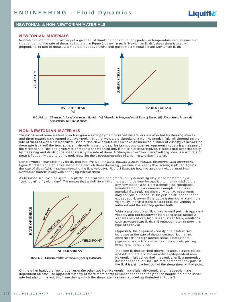
NEWTONIAN MATERIALSNewton deduced that the viscosity of a given liquid should be constant at any particular temperature and pressure andindependent of the rate of shear, as illustrated in Figure 1 below. In such “Newtonian fluids”, shear stress is directlyproportional to rate of shear. At temperatures above their cloud points most mineral oils are Newtonian fluids.
NON-NEWTONIAN MATERIALSThe viscosities of some materials, such as greases and polymer-thickened mineral oils, are affected by shearing effects, and these materials are termed Non-Newtonian. In other words, the viscosity of a Non-Newtonian fluid will depend on therate of shear at which it is measured. Since a Non-Newtonian fluid can have an unlimited number of viscosity values (as theshear rate is varied) the term apparent viscosity is used to describe its viscous properties. Apparent viscosity is a measure ofthe resistance to flow at a given rate of shear. It has meaning only if the rate of shear is given. It is obtained experimentallyby measuring and dividing the shear stress by the rate of shear. A “rheogram” or “flow curve” relating shear stress to rate ofshear is frequently used to completely describe the viscous properties of a non-Newtonian material.
Non-Newtonian materials may be divided into five types: plastic, pseudo-plastic, dilatant, thixotropic, and rheopectic.Figure 2 presents characteristic rheograms in which shear stress (e.g., pressure in a steady flow system) is plotted against the rate of shear (which is proportional to the flow velocity). Figure 3 illustrates how the apparent viscosities of Non-Newtonian materials vary with changing rates of shear.
As illustrated in curve 1 of Figure 2, a plastic material such as a grease, putty or molding clay, is characterized by a“yield point” or “yield value”. This means that a definite minimum stress or force must be applied to the material before
any flow takes place. From a rheological standpoint,tomato ketchup is a common example of a plasticmaterial. If a bottle is shaken only gently, its contents may not flow out because its “yield point” has not beenexceeded. However, if the bottle is struck or shaken morevigorously, the yield point is exceeded, the viscosity isreduced and the ketchup gushes forth.
While a pseudo-plastic fluid has no yield point, its apparentviscosity also decreases with increasing shear rates butstabilizes only at very high rates of shear. Many emulsionssuch as water-base fluids and resinous materials show thistype of behavior.
Oppositely, the apparent viscosity of a dilatant fluidincreases as the rate of shear increases. Such a fluid often solidifies at high rates of shear. Examples arepigmented-vehicle suspensions such as paints, printing inks and some starches.
The three fluids described above – plastic, pseudo-plasticand dilatant are also known as time-independent non-Newtonian fluids since their rheological or flow propertiesare independent of time. The rate of shear at any point inthe fluid is a simple function of the shear stress at that point.
On the other hand, the flow properties of the other two Non-Newtonian materials – thixotropic and rheopectic – aredependent on time. The apparent viscosity of these more complex fluids depends not only on the magnitude of the shearrate but also on the length of time during which the shear rate has been applied, as illustrated in Figure 3.
RATE OF SHEAR
NEWTONIAN OIL
VIS
CO
SIT
Y
NON-NEWTONIAN OIL
R0
RATE OF SHEAR(A)
VIS
CO
SIT
Y
RATE OF SHEAR(B)
SH
EA
R S
TR
ES
S
RATE OF SHEAR
AP
PAR
EN
T V
ISC
OS
ITY
TIME AT CONSTANT SHEAR
AP
PAR
EN
T V
ISC
OS
ITY
DILATANT
PSEUDOPLASTIC
RHEOPECTIC
THIXOTROPIC
YIELD POINT
SHEAR STRESS
RA
TE
OF
SH
EA
R
PLASTIC
NEWTONIA
N
THIX
OTR
OPI
C
PSEUDOPLA
STIC
DIL
ATAN
T
3
24 1
FIGURE 2: Characteristics of various types of materials.
FIGURE 1: Characteristics of Newtonian liquids. (A) Viscosity is independent of Rate of Shear. (B) Shear Stress is directly proportional to Rate of Shear.
Chemical Processing Pumps
Chemical Processing Pumps
TM
TM
TM
109t e l . 9 0 8 . 5 1 8 . 0 7 7 7 f a x . 9 0 8 . 5 1 8 . 1 8 4 7 w w w . l i q u i f l o . c o m
NEWTONIAN & NON-NEWTONIAN MATERIALS (continued)
E N G I N E E R I N G - F l u i d D y n a m i c s
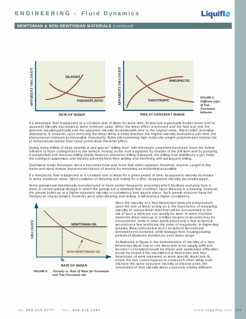
If a thixotropic fluid is subjected to a constant rate of shear for some time, its structure is gradually broken down and itsapparent viscosity decreases to some minimum value. When the shear effect is removed and the fluid is at rest, thestructure rebuilds gradually and the apparent viscosity increases with time to the original value. This is called reversiblethixotrophy. If, however, upon removing the shear stress, a value less than the original viscosity is obtained with time, thephenomenon is known as irreversible thixotrophy. Some oils containing high molecular weight polymers and mineral oilsat temperatures below their cloud points show this latter effect.
During rotary drilling of deep oil wells, a very special “drilling mud” with thixotropic properties is pumped down the hollowdrill stem to force cuttings back to the surface. As long as the mud is agitated by rotation of the drill stem and by pumping,it remains fluid and removes drilling debris. However, whenever drilling is stopped, the drilling mud solidifies to a gel, holds the cuttings in suspension, and thereby prevents them from settling and interfering with subsequent drilling.
Quicksand is also thixotropic since it becomes more and more fluid when agitated; therefore, anyone caught in thiswater-and-sand mixture improves his chance of survival by remaining as motionless as possible.
If a rheopectic fluid is subjected to a constant rate of shear for a given period of time, its apparent viscosity increasesto some maximum value. Upon cessation of shearing and resting for a time, its apparent viscosity decreases again.
Some greases are intentionally manufactured to have partial rheopectic properties which facilitate pumping from adrum or central grease storage in which the grease is in a relatively fluid condition. Upon shearing in a bearing, however,the grease builds up to a higher apparent viscosity or consistency and stays in place. Such grease does not have fullrheopectic characteristics, however, since after shearing and resting, it still retains a higher consistency.
Since the viscosity of a Non-Newtonian lubricant is dependentupon the rate of shear acting on it, the importance of measuringviscosity at various shear rates that will be encountered in theuse of such a lubricant can readily be seen. In some machineelements, shear rates up to 3 million reciprocal seconds may beencountered, while in other applications only a few reciprocalseconds or a few tenths are the order of magnitude. In dispensinggreases, shear rates as low as 0.1 reciprocal seconds aresometimes encountered, while leakage from housings duringperiods of shutdown involves an even lower range.
As illustrated in Figure 4, the determination of viscosity of a Non-Newtonian liquid only at one shear rate is not usually sufficient.Incorrect conclusions would be drawn and application difficultieswould be invited if the viscosities of a Newtonian and Non-Newtonian oil were measured at some specific shear rate R0,where the two curves happen to cross each other. While both oils have the same apparent viscosity at this one point, theremainders of their viscosity-shear curves are entirely different.RATE OF SHEAR
NEWTONIAN OIL
VIS
CO
SIT
Y
NON-NEWTONIAN OIL
R0
RATE OF SHEAR(A)
VIS
CO
SIT
Y
RATE OF SHEAR(B)
SH
EA
R S
TR
ES
S
RATE OF SHEAR
AP
PAR
EN
T V
ISC
OS
ITY
TIME AT CONSTANT SHEAR
AP
PAR
EN
T V
ISC
OS
ITY
DILATANT
PSEUDOPLASTIC
RHEOPECTIC
THIXOTROPIC
FIGURE 3:Different typesof Non-Newtonianbehavior.
FIGURE 4: Viscosity vs. Rate of Shear for Newtonianand Non-Newtonian oils.
RATE OF SHEAR
NEWTONIAN OIL
VIS
CO
SIT
Y
NON-NEWTONIAN OIL
R0
RATE OF SHEAR(A)
VIS
CO
SIT
Y
RATE OF SHEAR(B)
SH
EA
R S
TR
ES
S
RATE OF SHEAR
AP
PAR
EN
T V
ISC
OS
ITY
TIME AT CONSTANT SHEARA
PPA
RE
NT
VIS
CO
SIT
Y
DILATANT
PSEUDOPLASTIC
RHEOPECTIC
THIXOTROPIC

Chemical Processing Pumps
Chemical Processing Pumps
TM
TM
TM
110 t e l . 9 0 8 . 5 1 8 . 0 7 7 7 f a x . 9 0 8 . 5 1 8 . 1 8 4 7 w w w . l i q u i f l o . c o m
E N G I N E E R I N G - F l u i d D y n a m i c s
VISCOSITY vs. TEMPERATURE for SPECIFIC CHEMICALS
Coordinates for Chart on following page:
Liquid X YAcetaldehyde................................... 15.2 4.8Acetic acid, 100%............................. 12.1 14.2Acetic acid, 70%............................... 9.5 17.0Acetic anhydride ............................. 12.7 12.8Acetone, 100%...................................14.5 7.2Acetone, 35%..................................... 7.9 15.0Acetonitrile......................................... 14.4 7.4Acrylic acid........................................ 12.3 13.9Allyl alcohol........................................ 10.2 14.3Allyl bromide ......................................14.4 9.6Allyl Iodide.......................................... 14.0 11.7Ammonia, 100%................................. 12.6 2.0Ammonia, 26%................................... 10.1 13.9Amyl acetate..................................... 11.8 12.5Amyl alcohol....................................... 7.5 18.4Aniline.................................................. 8.1 18.7Anisole.................................................12.3 13.5Arsenic trichloride.............................. 13.9 14.5Benzene.............................................. 12.5 10.9Brine, CaCl2, 25%............................... 6.6 15.9Brine, NaCl, 25%................................. 10.2 16.6Bromine............................................... 14.2 13.2Bromotoluene.................................... 20.0 15.9Butyl acetate..................................... 12.3 11.0Butyl acrylate..................................... 11.5 12.6Butyl alcohol....................................... 8.6 17.2Butyric acid........................................ 12.1 15.3Carbon dioxide................................. 11.6 0.3Carbon disulfide................................ 16.1 7.5Carbon tetrachloride........................ 12.7 13.1Chlorobenzene.................................. 12.3 12.4Chloroform......................................... 14.4 10.2Chlorosulfonic acid........................... 11.2 18.1Chlorotoluene, ortho........................ 13.0 13.3Chlorotoluene, meta........................ 13.3 12.5Chlorotoluene, para......................... 13.3 12.5Cresol, meta....................................... 2.5 20.8Cyclohexanol..................................... 2.9 24.3Cyclohexane...................................... 9.8 12.9Dibromomethane.............................. 12.7 15.8Dichloroethane.................................. 13.2 12.2Dichloromethane...............................14.6 8.9Diethyl ketone.................................... 13.5 9.2Diethyl oxalate................................... 11.0 16.4Diethylene glycol............................... 5.0 24.7Diphenyl.............................................. 12.0 18.3Dipropyl ether.....................................13.2 8.6Dipropyl oxalate.................................10.3 17.7Ethyl acetate..................................... 13.7 9.1Ethyl acrylate..................................... 12.7 10.4Ethyl alcohol, 100%............................ 10.5 13.8Ethyl alcohol, 95%.............................. 9.8 14.3Ethyl alcohol, 40%.............................. 6.5 16.6Ethyl benzene ................................... 13.2 11.5Ethyl bromide .................................... 14.5 8.12-Ethyl butyl acrylate ........................11.2 14.0Ethyl chloride .....................................14.8 6.0Ethyl ether ..........................................14.5 5.3Ethyl formate .....................................14.2 8.42-Ethyl hexyl acrylate ....................... 9.0 15.0Ethyl iodide ........................................14.7 10.3Ethyl propionate ............................... 13.2 9.9Ethyl propyl ether ............................. 14.0 7.0Ethyl sulfide ........................................ 13.8 8.9Ethylene bromide ............................. 11.9 15.7Ethylene chloride ..............................12.7 12.2Ethylene glycol................................... 6.0 23.6Ethylidene chloride ...........................14.1 8.7Fluorobenzene .................................. 13.7 10.4Formic acid ....................................... 10.7 15.8Freon-11 ............................................. 14.4 9.0Freon-12 ............................................. 16.8 15.6Freon-21 ............................................. 15.7 7.5Freon-22 ............................................. 17.2 4.7
Liquid X YFreon-113............................................ 12.5 11.4Glycerol, 100% .................................. 2.0 30.0Glycerol, 50% .................................... 6.9 19.6Heptane ............................................ 14.1 8.4Hexane .............................................. 14.7 7.0Hydrochloric acid, 31.5% ................. 13.0 16.6Iodobenzene .................................... 12.8 15.9Isobutyl alcohol ................................ 7.1 18.0Isobutyric acid .................................. 12.2 14.4Isopropyl alcohol .............................. 8.2 16.0Isopropyl bromide ............................ 14.1 9.2Isopropyl chloride ............................. 13.9 7.1Isopropyl iodide ............................... 13.7 11.2Kerosene ............................................ 10.2 16.9Linseed oil, raw .................................. 7.5 27.2Mercury ..............................................18.4 16.4Methanol, 100% ................................ 12.4 10.5Methanol, 90% .................................. 12.3 11.8Methanol, 40% .................................. 7.8 15.5Methyl acetate .................................14.2 8.2Methyl acrylate .................................13.0 9.5Methyl i-butyrate .............................. 12.3 9.7Methyl n-butyrate ............................. 13.2 10.3Methyl chloride ................................. 15.0 3.8Methyl ethyl ketone ......................... 13.9 8.6Methyl formate ................................. 14.2 7.5Methyl iodide .................................... 14.3 9.3Methyl propionate ........................... 13.5 9.0Methyl propyl ketone ...................... 14.3 9.5Methyl sulfide .................................... 15.3 6.4Napthalene ....................................... 7.9 18.1Nitric acid, 95% ................................. 12.8 13.8Nitric acid, 60% ................................. 10.8 17.0Nitrobenzene .................................... 10.6 16.2Nitrogen dioxide ............................... 12.9 8.6Nitrotoluene........................................11.0 17.0Octane .............................................. 13.7 10.0Octyl alcohol .................................... 6.6 21.1Pentachloroethane ......................... 10.9 17.3Pentane ............................................. 14.9 5.2Phenol ................................................ 6.9 20.8Phosphorus tribromide ..................... 13.8 16.7Phosphorus trichloride ...................... 16.2 10.9Propionic acid ...................................12.8 13.8Propyl acetate .................................. 13.1 10.3Propyl alcohol ................................... 9.1 16.5Propyl bromide ................................. 14.5 9.6Propyl chloride .................................. 14.4 7.5Propyl formate .................................. 13.1 9.7Propyl iodide ..................................... 14.1 11.6Sodium ............................................... 16.4 13.9Sodium hydroxide, 50% .................... 3.2 25.8Stannic chloride ................................13.5 12.8Succinonitrile ..................................... 10.1 20.8Sulfur dioxide ..................................... 15.2 7.1Sulfuric acid, 110% ............................. 7.2 27.4Sulfuric acid, 100% ............................. 8.0 25.1Sulfuric acid, 98% .............................. 7.0 24.8Sulfuric acid, 60% .............................. 10.2 21.3Sulfuryl chloride ................................ 15.2 12.4Tetrachloroethane ............................11.9 15.7Thiophene ..........................................13.2 11.0Titanium tetrachloride ......................14.4 12.3Toluene .............................................. 13.7 10.4Trichloroethylene .............................. 14.8 10.5Triethylene glycol ............................. 4.7 24.8Turpentine .......................................... 11.5 14.9Vinyl acetate .................................... 14.0 8.8Vinyl toluene ..................................... 13.4 12.0Water ..................................................10.2 13.0Xylene, ortho ..................................... 13.5 12.1Xylene, meta .....................................13.9 10.6Xylene, para ......................................13.9 10.9

Chemical Processing Pumps
Chemical Processing Pumps
TM
TM
TM
111t e l . 9 0 8 . 5 1 8 . 0 7 7 7 f a x . 9 0 8 . 5 1 8 . 1 8 4 7 w w w . l i q u i f l o . c o m
VISCOSITY vs. TEMPERATURE for SPECIFIC CHEMICALS (continued)
E N G I N E E R I N G - F l u i d D y n a m i c s
TEMPERATURE VISCOSITYCentipoises˚C ˚F
30
28
26
24
22
20
18
16
14
12
10
8
6
4
2
0
1
2
3
4
5
6
78910
0.90.80.7
0.6
0.5
0.4
0.3
0.2
0.1
2 4 6 8 10
X12 14 16 180
200
190
180
170
160
30
20
10
0
-10
150
140
130
120
110
100
90
80
70
60
50
-20
-30
-10
-20
100
90
80
70
60
50
40
30
20
10
0
140
130
120
110
170
160
150
200
190
180
230 220 210
260 250 240
300 290 280 270
340 330 320 310
390 380 370 360 350
10090807060
50
40
30
20
20
40
Y
Example: How to find viscosity of a specific chemical at a specified temperature.Find the viscosity of 60% Sulfuric Acid at 80˚F1) Locate Sulfuric acid, 60% in chemical list on previous page.2) Plot X-Y coordinates (X=10.2, Y=21.3) in the above grid.3) Draw a line from 80˚F through the plotted point (see above).4) Viscosity for 60% Sulfuric Acid at 80˚F is 5.8 centipoises.

Gallons per Minute
1000
Pipe Velocity Ft. Per Sec.
Fric
tion
Loss
Mod
ulus
for
100 F
eet
of P
ipe
20 30
80
100
300
125
400
250
150
200
800
600
500
1000
3000
1250
2500
1500
2000
4000
8000
6000
5000
1000
0
(15.7)
(43.2)
(20.6)
(32.1)
(54)
(108)
(87)
(65)
(130)
(26.4)
(1298
)
200
300
700 600
500
400
900 800
100
20
30
7060
50
40
9080
10
2
3
7
6
5
4
98
1
Wat
er (1
.13)
" Steel Pipe (0.662" I.D.)(7.
4)
60
50
2 3 74 5 6 108 9
.4 .5 .7 .8 2.6 31.0.9 4 5 7 86 109 20
(173)
(541)
(217)
(433)
(271)
(325)
(649)
(1732
)
(1082
)
(865)
(2165
)
.5 .8.6 .7
(CS)
30
(0.46)
1/2
(10.3)
VISCOSITY-SSU
1.9.4.3
50 (7
.4)
Pipe Losses (PSI) = Modulus x Specific Gravity Pipe Losses (Feet of Head) = Modulus x 2.31
100
(20.
6)
LOWER LIMIT forLAMINAR FLOW
Chemical Processing Pumps
Chemical Processing Pumps
TM
TM
TM
112 t e l . 9 0 8 . 5 1 8 . 0 7 7 7 f a x . 9 0 8 . 5 1 8 . 1 8 4 7 w w w . l i q u i f l o . c o m
FRICTION LOSS MODULUS - Introduction
E N G I N E E R I N G - F l u i d D y n a m i c s
DETERMINATION OF FRICTION LOSS MODULUSThe graphs on the following pages are used for calculating pressure losses in piping systems. If the Flow Rate and Viscosityare known, the graph gives the Friction Loss Modulus used for calculating the Friction Loss in Lengths of Pipe.
The area above the dotted line on the graph indicates the region of Laminar Flow; below the dotted line is theregion of Turbulent Flow.
The line for Water (1.13 CS) shows that for flows less than 1.5 GPM using 1/2” pipe that the Friction Loss Modulus is negligible.
The line for Fluid Viscosities of (.46 CS) lies between that of water and the lower limit line indicating turbulent flow.
The graph shows some normally expected trends:(1) Friction Loss Modulus increases as the flow rate increases.
(2) Friction Loss Modulus increases as the viscosity of the fluid increases.
Example 1:
1/2” = Pipe Size3 GPM = Flow Rate100 SSU = ViscositySpecific Gravity = 1Length of Pipe = 150 ft.
From the graph the Flow Loss Modulus = 11
Pipe Friction Loss = 11 PSI x 150 ft = 17 PSI100 ft
Example 2:
1/2” = Pipe Size10 GPM = Flow Rate100 SSU = ViscositySpecific Gravity = 1.5Length of Pipe = 150 ft.
From the graph the Flow Loss Modulus = 68
Pipe Friction Loss = 68 PSI x 150 ft x 1.5 = 153 PSI100 ft
SAMPLEFRICTION LOSSMODULUS GRAPHFOR 1/2” PIPE
Example 2:
Example 1:
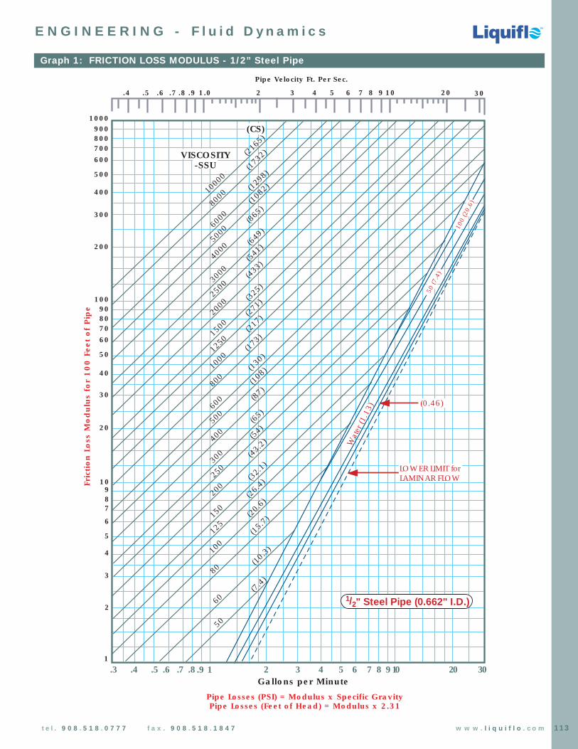
113t e l . 9 0 8 . 5 1 8 . 0 7 7 7 f a x . 9 0 8 . 5 1 8 . 1 8 4 7 w w w . l i q u i f l o . c o m
Graph 1: FRICTION LOSS MODULUS - 1/2” Steel Pipe
Gallons per Minute
1000
Pipe Velocity Ft. Per Sec.Fr
ictio
n Lo
ss M
odul
us f
or 1
00 F
eet
of P
ipe
20 30
80
100
300
125
400
250
150
200
800
600
500
1000
3000
1250
2500
1500
2000
4000
8000
6000
5000
1000
0
(15.7)
(43.2)
(20.6)
(32.1)
(54)
(108)
(87)
(65)
(130)
(26.4)
(1298
)
200
300
700 600
500
400
900 800
100
20
30
7060
50
40
9080
10
2
3
7
6
5
4
98
1
Wat
er (1
.13)
" Steel Pipe (0.662" I.D.)(7.
4)
60
50
2 3 74 5 6 108 9
.4 .5 .7 .8 2.6 31.0.9 4 5 7 86 109 20
(173)
(541)
(217)
(433)
(271)
(325)
(649)
(1732
)
(1082
)
(865)
(2165
)
.5 .8.6 .7
(CS)
30
(0.46)
1/2
(10.3)
VISCOSITY-SSU
1.9.4.3
50 (7
.4)
Pipe Losses (PSI) = Modulus x Specific Gravity Pipe Losses (Feet of Head) = Modulus x 2.31
100
(20.
6)LOWER LIMIT forLAMINAR FLOW
E N G I N E E R I N G - F l u i d D y n a m i c s
Chemical Processing Pumps
Chemical Processing Pumps
TM
TM
TM

114 t e l . 9 0 8 . 5 1 8 . 0 7 7 7 f a x . 9 0 8 . 5 1 8 . 1 8 4 7 w w w . l i q u i f l o . c o m
Graph 2: FRICTION LOSS MODULUS - 3/4” Steel Pipe
1000
20 5030 40
80
100
300
125
400
250
150
200
800
600
500
1000
3000
1250
2500
1500
2000
4000
8000
6000
5000
1000
0
(15.7)
(43.2)
(20.6)
(32.1)
(54)
(108)
(87)
(65)
(130)
(26.4)
(1298
)
200
300
700600
500
400
900800
100
20
30
7060
50
40
9080
10
.2
.3
.7
.6
.5
.4
.9
.8
.1
Wat
er (1
.13)
" Steel Pipe (0.824" I.D.)
(7.4)
60
50
2 3 74 5 6 108 9
.4 .5 .7 .8 2.6 31.0.9 4 5 7 86 109 20.3
(173)
(541)
(217)
(433)
(271)
(325)
(649)
(1732
)
(1082
)
(865)
(2165
)
.5 .8.6 .7
(CS)
30
(0.46)
3/4(10.3)
200
(43.
2)
100
(20.
6)
VISCOSITY-SSU
1.9Gallons per Minute
Pipe Velocity Ft. Per Sec.Fr
ictio
n Lo
ss M
odul
us f
or 1
00 F
eet
of P
ipe
Pipe Losses (PSI) = Modulus x Specific GravityPipe Losses (Feet of Head) = Modulus x 2.31
LOWER LIMIT forLAMINAR FLOW
E N G I N E E R I N G - F l u i d D y n a m i c s
Chemical Processing Pumps
Chemical Processing Pumps
TM
TM
TM

Chemical Processing Pumps
Chemical Processing Pumps
TM
TM
TM
115t e l . 9 0 8 . 5 1 8 . 0 7 7 7 f a x . 9 0 8 . 5 1 8 . 1 8 4 7 w w w . l i q u i f l o . c o m
Graph 3: FRICTION LOSS MODULUS - 1” Steel Pipe
100
20 30 7040 50 60
80
100
300
125
400
250
150
200
800
600
500
1000
3000
1250
2500
1500
2000
4000
8000
6000
5000
1000
0VISCOSITY
-SSU
(15.7)
(43.2)
(20.6)
(32.1)
(26.4)
(54)
(108)
(87)
(65)
(130)
(1298
)
20
30
70 60
50
40
90 80
10
2
3
76
5
4
98
1.0
.2
.3
.7
.6
.5
.4
.9
.8
.1
Wat
er (1
.13)
1" Steel Pipe (1.049" I.D.)
(10.3)
(7.4)
60
50
2 3 74 5 6 108 9
.4 .5 .7 .8 2.6 31.0.9 4 5 7 86 109 20.3
(0.46)
(173)
(541)
(217)
(433)
(271)
(325)
(649)
(1732
)
(1082
)
(865)
(2165
)
.7 1.0.8 .9
(CS)
Gallons per Minute
Pipe Velocity Ft. Per Sec.Fr
ictio
n Lo
ss M
odul
us f
or 1
00 F
eet
of P
ipe
Pipe Losses (PSI) = Modulus x Specific Gravity Pipe Losses (Feet of Head) = Modulus x 2.31
100 (
20.6)
50 (7
.4)
LOWER LIMIT forLAMINAR FLOW
E N G I N E E R I N G - F l u i d D y n a m i c s
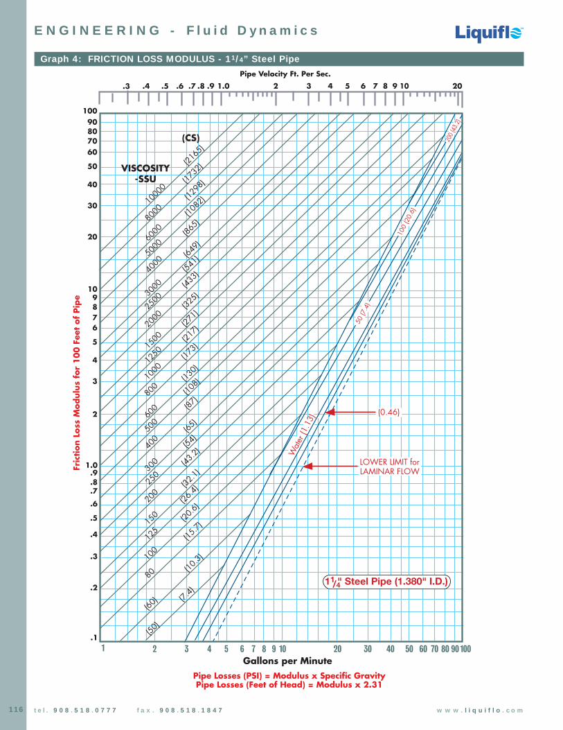
116 t e l . 9 0 8 . 5 1 8 . 0 7 7 7 f a x . 9 0 8 . 5 1 8 . 1 8 4 7 w w w . l i q u i f l o . c o m
Graph 4: FRICTION LOSS MODULUS - 11/4” Steel Pipe
100
20 30 7040 50 60
80
100
300
125
400
250
150
200
800
600
500
1000
3000
1250
2500
1500
2000
4000
8000
6000
5000
1000
0
VISCOSITY-SSU
(CS)
(173)
(541)
(217)
(433)
(271)
(325)
(649)
(1732
)
(1082
)
(865)
(2165
)
(15.7)
(43.2)
(20.6)
(32.1)
(26.4)
(54)
(108)
(87)
(65)
(130)
(1298
)
20
30
7060
50
40
9080
10
2
3
76
5
4
98
1.0
.2
.3
.7
.6
.5
.4
.9
.8
.1
10080 90
Wat
er (1
.13)
1/41 " Steel Pipe (1.380" I.D.)(10
.3)
(7.4)
(60)
(50)
2 3 74 5 6 108 9
.4 .5 .7 .8 2.6 31.0.9 4 5 7 86 109 20.3
(0.46)
Gallons per Minute
Pipe Velocity Ft. Per Sec.Fr
ictio
n Lo
ss M
odul
us f
or 1
00 F
eet
of P
ipe
Pipe Losses (PSI) = Modulus x Specific GravityPipe Losses (Feet of Head) = Modulus x 2.31
50 (7
.4)
100
(20.
6)
200 (
43.2)
1
LOWER LIMIT forLAMINAR FLOW
E N G I N E E R I N G - F l u i d D y n a m i c s
Chemical Processing Pumps
Chemical Processing Pumps
TM
TM
TM
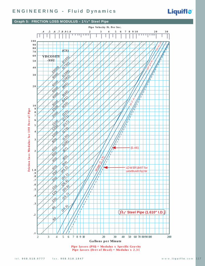
Chemical Processing Pumps
Chemical Processing Pumps
TM
TM
TM
117t e l . 9 0 8 . 5 1 8 . 0 7 7 7 f a x . 9 0 8 . 5 1 8 . 1 8 4 7 w w w . l i q u i f l o . c o m
Graph 5: FRICTION LOSS MODULUS - 11/2” Steel Pipe
100
8762 9 10 20 30 7040 50 60
VISCOSITY-SSU
(CS)
(173)
(649)
(217)
(541)
(271)(325)
(1082
)
(1732
)
(1298
)
(865)
(2165
)
(10.3)
(43.2)
(15.7)
(32.1)
(26.4)
(54)
(108)
(87)
(65)
(130)
20
30
70 60
50
40
90 80
10
2
3
7
6
5
4
98
1.0
.2
.3
.7
.6
.5
.4
.9
.8
.11008090
Wat
er (1
.13)
1/21 " Steel Pipe (1.610" I.D.)
.4 .5 .7 .8 2.6 31.0.9 4 5 7 86 109 3020
80
100
300
125
400
250
150
200
800
600
500
1000
3000
1250
2500
1500
2000
4000
8000
6000
5000
1000
0
(433)
60
(20.6)
2003 4 5
(0.46)
Gallons per Minute
Pipe Velocity Ft. Per Sec.Fr
ictio
n Lo
ss M
odul
us f
or 1
00 F
eet
of P
ipe
Pipe Losses (PSI) = Modulus x Specific Gravity Pipe Losses (Feet of Head) = Modulus x 2.31
200
(43.
2)
100
(20.
6)
50 (7
.4)
LOWER LIMIT forLAMINAR FLOW
E N G I N E E R I N G - F l u i d D y n a m i c s
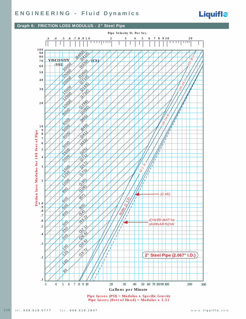
118 t e l . 9 0 8 . 5 1 8 . 0 7 7 7 f a x . 9 0 8 . 5 1 8 . 1 8 4 7 w w w . l i q u i f l o . c o m
Graph 6: FRICTION LOSS MODULUS - 2” Steel Pipe
100
8 7 6 5 9 10 20 30 70 40 50 60
80
100
300
125
400
250
150
200
800
600
500
1000
3000
1250
2500
1500
2000
4000
8000
6000
5000
1000
0
VISCOSITY-SSU
(173)
(541)
(217)
(433)
(271)
(325)
(649)
(1732
)
(1082
)
(865)
(2165
)
(15.7)
(43.2)
(20.6)
(32.1)
(26.4)
(54)
(108)
(87)
(65)
(130)
(1298
)20
30
70 60
50
40
90 80
10
2
3
76
5
4
98
1.0
.2
.3
.7
.6
.5
.4
.9
.8
.1100 80 90 200 300
Wat
er (1
.13)
2" Steel Pipe (2.067" I.D.)
.4 .5 .7 .8 2.6 31.0.9 4 5 7 86 109 20
400
(87)
1250
0
2500
0
2000
0
1500
0
3000
0(43
30)
(2710
)
(5410
)
(3250
)
(6490
)
(CS)
4 3
.3
(0.46)
Gallons per Minute
Pipe Velocity Ft. Per Sec.Fr
ictio
n Lo
ss M
odul
us f
or 1
00
Fee
t of
Pip
e
Pipe Losses (PSI) = Modulus x Specific Gravity Pipe Losses (Feet of Head) = Modulus x 2.31
200
(43.
2)
100
(20.
6)
50 (7
.4)
LOWER LIMIT forLAMINAR FLOW
E N G I N E E R I N G - F l u i d D y n a m i c s
Chemical Processing Pumps
Chemical Processing Pumps
TM
TM
TM
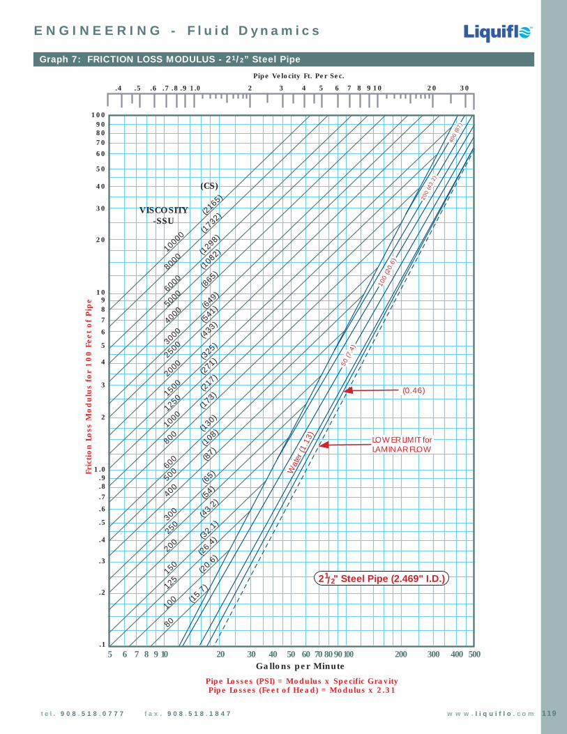
Chemical Processing Pumps
Chemical Processing Pumps
TM
TM
TM
119t e l . 9 0 8 . 5 1 8 . 0 7 7 7 f a x . 9 0 8 . 5 1 8 . 1 8 4 7 w w w . l i q u i f l o . c o m
Graph 7: FRICTION LOSS MODULUS - 21/2” Steel Pipe
100
8765 9 10 20 30 7040 50 60
80
100
300
125
400
250
150
200
800
600
500
1000
3000
1250
2500
1500
2000
4000
8000
6000
5000
1000
0
VISCOSITY-SSU
(CS)
(173)
(541)
(217)
(433)
(271)
(325)
(649)
(1732
)
(1082
)
(865)
(2165
)
(15.7)
(43.2)
(20.6)
(32.1)
(26.4)
(54)
(108)
(87)
(65)
(130)
(1298
)20
30
70 60
50
40
90 80
10
2
3
7
6
5
4
98
1.0
.2
.3
.7
.6
.5
.4
.9
.8
.110080 90 200 300 400 500
Wat
er (1
.13)
1/22 " Steel Pipe (2.469" I.D.)
.4 .5 .7 .8 2.6 31.0.9 4 5 7 86 109 3020
(0.46)
Gallons per Minute
Pipe Velocity Ft. Per Sec.
Fric
tion
Loss
Mod
ulus
for
10
0 F
eet
of P
ipe
Pipe Losses (PSI) = Modulus x Specific Gravity Pipe Losses (Feet of Head) = Modulus x 2.31
400
(87)
200
(43.
2)
100
(20.
6)
50 (7
.4)
LOWER LIMIT forLAMINAR FLOW
E N G I N E E R I N G - F l u i d D y n a m i c s

Chemical Processing Pumps
Chemical Processing Pumps
TM
TM
TM
120 t e l . 9 0 8 . 5 1 8 . 0 7 7 7 f a x . 9 0 8 . 5 1 8 . 1 8 4 7 w w w . l i q u i f l o . c o m
Graph 8: FRICTION LOSS MODULUS - 3” Steel Pipe
100
300
400
250
150
200
800
600
500
1000
3000
1250
2500
1500
2000
4000
8000
6000
5000
1000
0
(43.2)
(20.6)
(32.1)
(54)
(108)
(87)
(65)
(130)
(26.4)
20
30
7060
50
40
90 80
10
2
3
7
6
5
4
98
1.0
.2
.3
.7
.6
.5
.4
.9
.8
.1
Wat
er (1
.13)
3" Steel Pipe (3.068" I.D.)
.4 .5 .7 .8 2.6 31.0.9 4 5 7 86 109 20
(CS)
VISCOSITY-SSU
200 30020 30 7040 50 60 10080 9086 7 109 400 600500
(1298
)
(173)
(541)
(217)
(433)
(271)
(325)
(649)
(1732
)
(1082
)
(865)
(2165
)
(0.46)
.3
125
100
Gallons per Minute
Pipe Velocity Ft. Per Sec.Fr
ictio
n Lo
ss M
odul
us f
or 1
00 F
eet
of P
ipe
Pipe Losses (PSI) = Modulus x Specific Gravity Pipe Losses (Feet of Head) = Modulus x 2.31
50 (7
.4)
100
(20.
6)
200
(43.
2)
400
(87)
LOWER LIMIT forLAMINAR FLOW
E N G I N E E R I N G - F l u i d D y n a m i c s

Chemical Processing Pumps
Chemical Processing Pumps
TM
TM
TM
121t e l . 9 0 8 . 5 1 8 . 0 7 7 7 f a x . 9 0 8 . 5 1 8 . 1 8 4 7 w w w . l i q u i f l o . c o m
RESISTANCE OF VALVES & FITTINGS TO FLOW OF FLUIDS
E N G I N E E R I N G - F l u i d D y n a m i c s
D d
Dd
Borda Entrance
Square Elbow
d/D–1/4
d/D–1/2
d/D–3/4
Ordinary Entrance
d/D–1/4
d/D–1/2
d/D–3/4
45˚ Elbow
Standard Tee
Gate Valve3/4 Closed
1/2 Closed
1/4 Closed
Fully Open
Long Sweep Elbow orrun of Standard Tee
Medium Sweep Elbow orrun of Tee reduced 1/4
(Above Chart Courtesy of CRANE CO.)
Standard Elbow or run ofTee reduced 1/2
Standard Tee Through Side Outlet
Close Return Bend
Angle Valve, Open
Globe Valve, Open
50
30
20
10
5
3
2
1
48
36
20
12
5
3
2
1
24
16
14
34
12
1
112
212
412
312
6
8
10
14
18
22
30
42
4
9
7
Insi
de
Dia
met
er, In
ches
Pip
e Si
ze, In
ches
0.5
Sudden Enlargement
Sudden Contraction
0.5
0.3
0.1
1
2
0.2
20
10
3
30
5
300
200
50
500
100
1000
2000
3000
Equi
vale
nt L
ength
of
Stra
ight
Pip
e, F
eet
Example: The dotted line shows that the resistanceof a 6-inch Standard Elbow is equivalent toapproximately 16 feet of 6-inch Standard pipe.
Note: For sudden enlargements or suddencontractions, use the smaller diameter (d) on thepipe size scale. The scale is based on flow of water.

Chemical Processing Pumps
Chemical Processing Pumps
TM
TM
TM
122 t e l . 9 0 8 . 5 1 8 . 0 7 7 7 f a x . 9 0 8 . 5 1 8 . 1 8 4 7 w w w . l i q u i f l o . c o m
FASTENER TORQUE SPECIFICATIONS
E N G I N E E R I N G - M e c h a n i c a l D a t a
FASTENER MAXIMUM TORQUE VALUES (inch-pounds)
SIZE 18-8 SS 316 SS Low Carbon Steel
5 - 40 7.7 8.1 6.95 - 44 9.4 9.8 8.5
6 - 32 9.6 10.1 8.76 - 40 12.1 12.7 10.9
8 - 32 19.8 20.7 17.88 - 36 22.0 23.0 19.8
10 - 24 22.8 23.8 20.810 - 32 31.7 33.1 29.7
1/4 - 20 75.2 78.8 65.01/4 - 28 94.0 99.0 90.0
5/16 - 18 132.0 138.0 129.05/16 - 24 142.0 147.0 139.0
3/8 - 16 236.0 247.0 212.03/8- 24 259.0 271.0 232.0
7/16 - 14 376.0 393.0 338.07/16 - 20 400.0 418.0 361.0
1/2 - 13 517.0 542.0 465.01/2 - 20 541.0 565.0 487.0
9/16 - 12 682.0 713.0 613.09/16 - 18 752.0 787.0 668.0
5/8 - 11 1110.0 1160.0 1000.05/8 - 18 1244.0 1301.0 1140.0
3/4 - 10 1530.0 1582.0 1259.03/4 - 16 1490.0 1558.0 1230.0
7/8 - 9 2328.0 2430.0 1919.07/8 - 14 2318.0 2420.0 1911.0
1 - 8 3440.0 3595.0 2832.01 - 14 3110.0 3250.0 2562.0
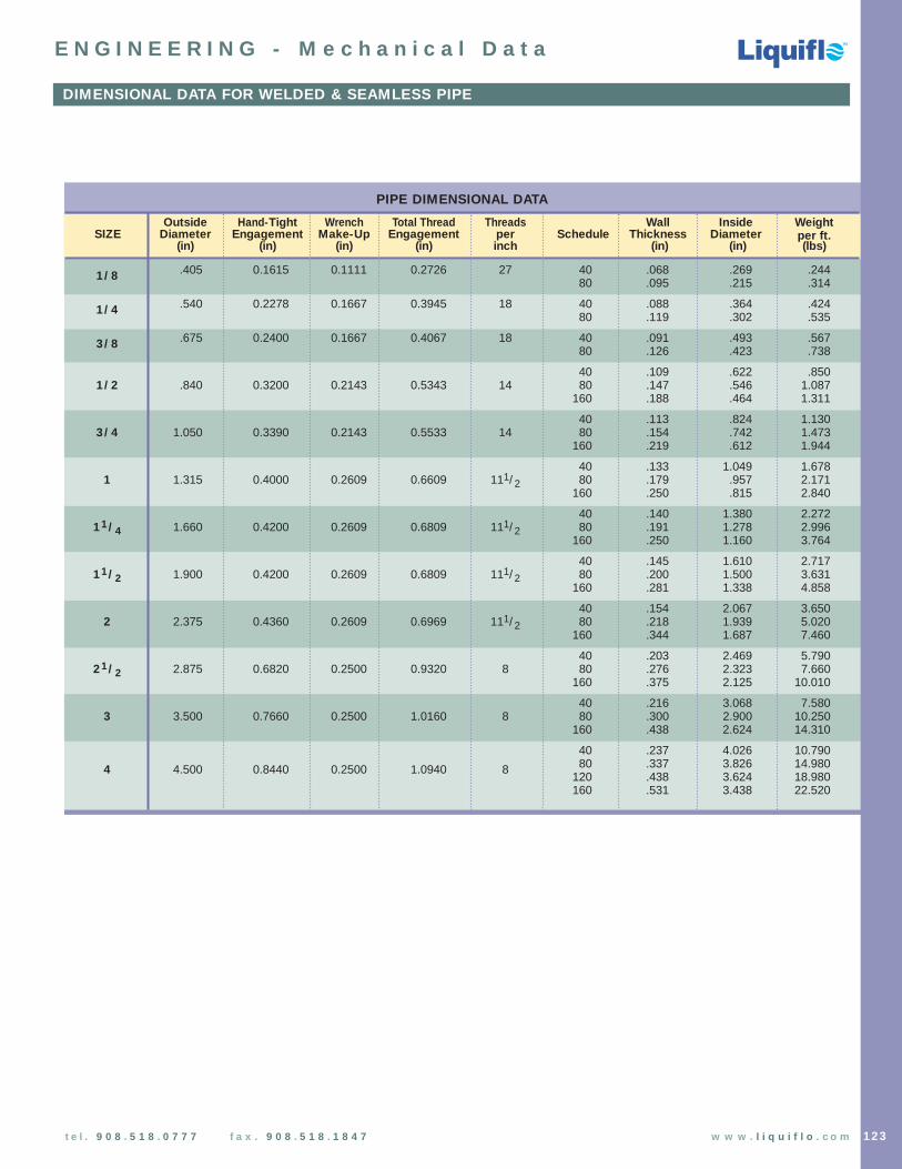
PIPE DIMENSIONAL DATA
Outside Hand-Tight Wrench Total Thread Threads Wall Inside WeightSIZE Diameter Engagement Make-Up Engagement per Schedule Thickness Diameter per ft.
(in) (in) (in) (in) inch (in) (in) (lbs)
1/8 .405 0.1615 0.1111 0.2726 27 40 .068 .269 .24480 .095 .215 .314
1/4 .540 0.2278 0.1667 0.3945 18 40 .088 .364 .42480 .119 .302 .535
3/8 .675 0.2400 0.1667 0.4067 18 40 .091 .493 .56780 .126 .423 .738
40 .109 .622 .8501/2 .840 0.3200 0.2143 0.5343 14 80 .147 .546 1.087
160 .188 .464 1.311
40 .113 .824 1.1303/4 1.050 0.3390 0.2143 0.5533 14 80 .154 .742 1.473
160 .219 .612 1.944
40 .133 1.049 1.6781 1.315 0.4000 0.2609 0.6609 111/2 80 .179 .957 2.171
160 .250 .815 2.840
40 .140 1.380 2.27211/4 1.660 0.4200 0.2609 0.6809 111/2 80 .191 1.278 2.996
160 .250 1.160 3.764
40 .145 1.610 2.71711/2 1.900 0.4200 0.2609 0.6809 111/2 80 .200 1.500 3.631
160 .281 1.338 4.858
40 .154 2.067 3.6502 2.375 0.4360 0.2609 0.6969 111/2 80 .218 1.939 5.020
160 .344 1.687 7.460
40 .203 2.469 5.79021/2 2.875 0.6820 0.2500 0.9320 8 80 .276 2.323 7.660
160 .375 2.125 10.010
40 .216 3.068 7.5803 3.500 0.7660 0.2500 1.0160 8 80 .300 2.900 10.250
160 .438 2.624 14.310
40 .237 4.026 10.790
4 4.500 0.8440 0.2500 1.0940 8 80 .337 3.826 14.980120 .438 3.624 18.980160 .531 3.438 22.520
Chemical Processing Pumps
Chemical Processing Pumps
TM
TM
TM
123t e l . 9 0 8 . 5 1 8 . 0 7 7 7 f a x . 9 0 8 . 5 1 8 . 1 8 4 7 w w w . l i q u i f l o . c o m
DIMENSIONAL DATA FOR WELDED & SEAMLESS PIPE
E N G I N E E R I N G - M e c h a n i c a l D a t a
Chemical Processing Pumps
Chemical Processing Pumps
TM
TM
TM
124 t e l . 9 0 8 . 5 1 8 . 0 7 7 7 f a x . 9 0 8 . 5 1 8 . 1 8 4 7 w w w . l i q u i f l o . c o m
ELECTRICAL STANDARDS & MOTOR ENCLOSURE TYPES
E N G I N E E R I N G - M o t o r s
IEEEThe Institute of Electrical and Electronics Engineers is a technical organization that publishes various recommendedpractices, which have been adopted as industry standards. Recommended practices do not require approval action or special testing.
NECNational Electric Code is an ASA standard sponsored by the national Fire Protection Association for the purpose of safe-guarding persons and buildings from electrical hazards arising from the use of electricity for light, heat, power, and other purposes.
NEMANational Electrical Manufacturers Association. Standards are voluntary that represent general practices in the industry.They define a product, process, or procedure with reference to nomenclature, composition, construction, dimensions,tolerances, operating characteristics, performance, quality, rating and testing.
Temperature Codes (“T” Codes)NEC requires explosion-proof motors to indicate the maximum operating surface temperature. A “T” Code is used as the temperature identification value and it is taken from the National Electrical Code. The “T” Code is based on theminimum ignition temperature of the substance to be found in the hazardous location. The Code, when marked on themotor nameplate, represents the highest temperature that could be obtained on the motor surface under any normal or abnormal operating conditions, including locked rotor, single phasing or over-loading, and is chosen to be below theignition temperature of the substance in the hazardous area.
Enclosure TypesThe selection of the proper enclosure is vital to the successful and safe operation of industrial motors. The user mustrecognize the specific environmental conditions and specify the correct enclosure.
Open Drip-proof Motor An ODP motor is an open machine having all openings limited in size to prevent accidental(ODP) contact with moving or hazardous parts. Internal parts are protected from drip, splash, and
falling objects. ODP motors are suitable for general industrial use in indoor locations with relatively clean atmospheres.
Totally Enclosed (TE) A totally enclosed motor prevents the free exchange of air between the inside andMotor outside of the motor case. They are not considered air-tight. Totally enclosed motors
are suitable for use in dusty, dirty locations and humid environments.
Totally Enclosed Non-Ventilated (TENV) – These motors are not equipped with a ventilation fan for totally cooling the outside skin. Generally limited to low horsepower ratings or short-time rated motors.
Totally Enclosed Fan-Cooled (TEFC) – Exterior surface of the motor is cooled by an externalfan on the motor shaft. Motor cooling is therefore dependent on motor speed.
Totally Enclosed Blower-Cooled (TEBC) – Cooling is achieved with an external blower that is mounted on the back of the motor. The blower provides continuous cooling that is independent of the motor shaft speed.
Explosion Proof Motor An Explosion-Proof (XP) motor is totally enclosed and designed to operate in an environmentfor Hazardous Locations in which flammable gas or vapor is present. This is accomplished by limiting the external
surface temperature of the motor below the ignition temperature of the hazardous gas or vapor surrounding the motor. It is very important that the end user order a motor with a proper temperature code. The enclosure is also designed to contain an explosion on theinside which may be caused by arcing, sparking, or abnormal heat. A flame caused bysuch a motor will not propagate the motor fits and ignite the gas or vapor surrounding themotor. An explosion-proof motor is suitable for operation in a Class I hazardous environment.
Dust Ignition Proof Motor A Dust Ignition-Proof (DIP) motor is a totally enclosed machine designed to operate safely for Hazardous Locations in flammable dust environments. The motor enclosure prevents the admittance of dust
inside the motor. Also, the motor is designed to operate cool enough as not to ignite anydust which might accumulate on the external surface of the motor. Should the motorbecome blanketed with dust and reduce its normal cooling, winding thermostats will takethe motor offline before the motor’s external surface temperature reaches the ignition temperature of the hazardous dust. A Dust Ignition Proof motor is suitable for operationin a Class II hazardous environment.

Chemical Processing Pumps
Chemical Processing Pumps
TM
TM
TM
125t e l . 9 0 8 . 5 1 8 . 0 7 7 7 f a x . 9 0 8 . 5 1 8 . 1 8 4 7 w w w . l i q u i f l o . c o m
E N G I N E E R I N G - M o t o r s
NEMA CHARTS – HAZARDOUS & NON-HAZARDOUS CLASSIFICATIONS
HAZARDOUS CLASSIFICATION (CLASS)CLASS I
GASES OR VAPORSCLASS II
DUSTCLASS III
FIBERS
DIVISION 1Hazardous vapors
present
DIVISION 2Hazardous vapors
contained butmay be present
DIVISION 2Surface-accumulated,
non-air suspended
DIVISION 2Handled
and stored
DIVISION 1Handled,
manufacturedor used
DIVISION 1Air suspended
GROUP AAcetylene
GROUP BHydrogen, etc.
GROUP CEther, UDMH,ethylene, etc.
GROUP DAcetone, hydrocarbons,
acetates, alcohols,etc.
GROUP FCarbon black, coal,
coke dust, etc.
GROUP GFlour, starch, grain,organic food stuffs,
etc.
GROUP EMetals: aluminum,magnesium, etc.
NO GROUPSTextiles, wood,synthetic fibers.
ENCLOSURES FOR NON-HAZARDOUS LOCATIONS
NEMAType 1 General Purpose – IndoorType 2 General Purpose – IndoorType 3 Dust-tight, Rain-tight and Sleet (Ice)-Resistant – OutdoorType 3R Rainproof and Sleet (Ice)-Resistant – OutdoorType 3S Dust-tight, Rain-tight and Sleet (Ice)-Proof – OutdoorType 4 Watertight and Dust-tight – Indoor and OutdoorType 4X Watertight, Dust-tight and Corrosion-Resistant
– Indoor and OutdoorType 4/12 Features of Type 4 and Type 12 combinedType 5 Superseded by Type 12 for Control ApparatusType 6 Submersible, Watertight, Dust-tight Rainproof
and Sleet (Ice)-Resistant – Indoor and Outdoor
Type 11 Corrosion-Resistant and Drip-proof – Oil immersed – Indoor Type 12 Industrial Use – Dust-tight and Drip-tight – IndoorType 13 Oil-tight and Dust-tight – Indoor
ENCLOSURES FOR HAZARDOUS LOCATIONSType 7 Class I, Group A, B, C or D
– Indoor Hazardous Locations – Air-break equipment
Type 8 Class I, Group A, B, C or D– Indoor Hazardous Locations – Oil immersed equipment
Type 9 Class II, Group E, F, or G– Indoor Hazardous Locations – Air-Brake equipment
Type 10 Bureau of Mines

Chemical Processing Pumps
Chemical Processing Pumps
TM
TM
TM
126 t e l . 9 0 8 . 5 1 8 . 0 7 7 7 f a x . 9 0 8 . 5 1 8 . 1 8 4 7 w w w . l i q u i f l o . c o m
E N G I N E E R I N G - M o t o r s
TORQUE, SPEED, POWER & EFFICIENCY
TORQUEThe Full Load Torque of a motor is expressed as follows:
Since different loads present different torque requirements at starting (break-away), minimum (pull-up), break-down (pull-out), and full load, the National Electrical Manufacturers Association (NEMA) has defined 4 design classes of squirrel cage induction motors, which are described in the following table:
NEMA STARTING STARTING BREAK-DOWN FULL LOAD TYPICALDESIGN TORQUE CURRENT TORQUE SLIP APPLICATIONS
A Normal High High Low Machine Tools
B Normal Normal Normal Normal General Industrial
C High Normal Normal Normal Loaded Compressors
D Very High Low –– High Punch Presses or Hoists
SPEED & SLIPSynchronous Speed vs. Rotor Speed:
The actual operating speed of an AC induction motor is determined by the synchronous speed and slip. Slip is the difference between the speed of the rotating magnetic field (which is always synchronous) and the rotor speed. Slip generally increases with an increase in motor torque; therefore, actual operating speedgenerally decreases with an increase in motor torque. (See figures on next page.)
POWERThe mechanical power output of a motor is given by:
EFFICIENCYMotor efficiency generally increases as the horsepower rating of the motor increases. High-efficiency motorscan save energy and money. The chart below shows typical annual cost savings from using a high-efficiency motor over a standard efficiency motor.
Chart based on $ .10 and 7,200 hours annual run time:kW-hr
HIGH EFFICIENCY STANDARD EFFICIENCY ELECTRICAL ENERGY SAVED ANNUAL SAVINGSHP MOTOR (%) MOTOR (%) POWER DIFF. (W) (kW-hr) ($ US)
1 84.0 76.5 87.1 627 63
1.5 85.5 78.5 117 840 84
2 86.5 80.8 122 876 88
3 88.5 79.9 272 1960 196
5 88.5 83.1 274 1972 197
7.5 90.2 83.8 474 3411 341
10 90.2 85.0 506 3643 364
15 91.7 86.5 734 5282 528
20 92.4 87.4 924 6651 665
50 93.6 90.4 1411 10157 1016
100 95.4 91.6 3244 23357 2336
Synchronous Speed (RPM) =Power Supply Frequency (Hz) x 120
Number of Poles (2, 4, 6, etc.)
Power (Hp) =Torque (in-lbs) x Speed (RPM)
63,025Power (kW) =
Torque (N-m) x Speed (Hz)
159.2
Motor Mech. Output Power Efficiency (%) =
Input Power x 100
Full-Load Torque (ft-lbs) =Power (Hp) x 5252
Full-Load Speed (RPM)
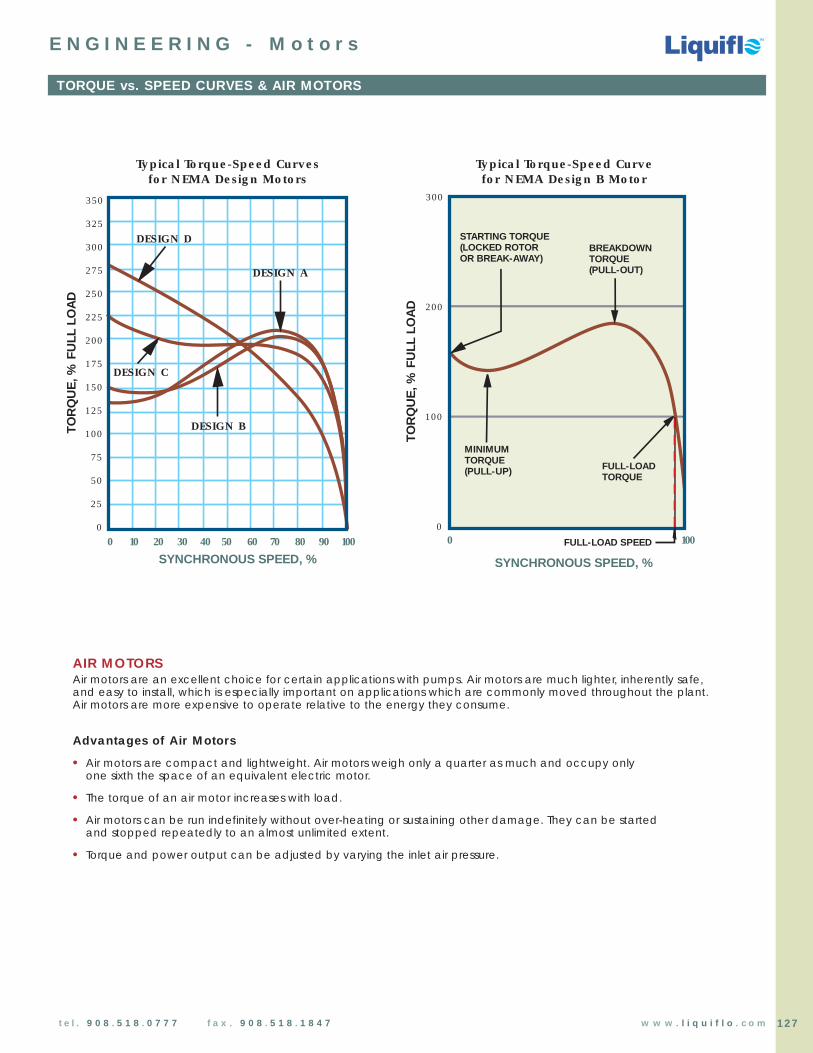
Chemical Processing Pumps
Chemical Processing Pumps
TM
TM
TM
127t e l . 9 0 8 . 5 1 8 . 0 7 7 7 f a x . 9 0 8 . 5 1 8 . 1 8 4 7 w w w . l i q u i f l o . c o m
TORQUE vs. SPEED CURVES & AIR MOTORS
E N G I N E E R I N G - M o t o r s
350
325
300
275
250
225
200
175
150
125
100
75
50
25
0
SYNCHRONOUS SPEED, %
DESIGN C
DESIGN A
DESIGN B
DESIGN D
TO
RQ
UE
, % F
ULL
LO
AD
0 10 20 30 40 50 60 70 90 10080
0
100
300
200
100
0
STARTING TORQUE(LOCKED ROTOROR BREAK-AWAY)
MINIMUMTORQUE(PULL-UP) FULL-LOAD
TORQUE
BREAKDOWNTORQUE(PULL-OUT)
SYNCHRONOUS SPEED, %
TO
RQ
UE
, % F
ULL
LO
AD
Typical Torque-Speed Curve for NEMA Design B Motor
FULL-LOAD SPEED
Typical Torque-Speed Curves for NEMA Design Motors
AIR MOTORSAir motors are an excellent choice for certain applications with pumps. Air motors are much lighter, inherently safe,and easy to install, which is especially important on applications which are commonly moved throughout the plant. Air motors are more expensive to operate relative to the energy they consume.
Advantages of Air Motors
• Air motors are compact and lightweight. Air motors weigh only a quarter as much and occupy onlyone sixth the space of an equivalent electric motor.
• The torque of an air motor increases with load.
• Air motors can be run indefinitely without over-heating or sustaining other damage. They can be started and stopped repeatedly to an almost unlimited extent.
• Torque and power output can be adjusted by varying the inlet air pressure.

NEMA MOTORS - Quick Reference Chart
E N G I N E E R I N G - M o t o r s
C-FACE MOTOR (Close-Coupled)
STANDARD MOTOR (Base Mounted)
U
R
S
C
N
U
E
BD
AB
BA
O
P
45˚ 45˚
AAH = HOLE
V
E
D
2F
H = HOLE BA2F AA = CONDUIT SIZE EE
AK
U
C P
O
D
BBXO
AH (56C-145TC)AH (182TC-256TC)
AB
THERMAL(optional)
TAP4 HOLES
Singlephaseonly
45˚ 45˚
NNoottee:: BBAA dimensions in blue apply only for Standard motor frames. See separate chart above for C-Face motor BBAA dimensions.
VAJ
Chemical Processing Pumps
Chemical Processing Pumps
TM
TM
TM
128 t e l . 9 0 8 . 5 1 8 . 0 7 7 7 f a x . 9 0 8 . 5 1 8 . 1 8 4 7 w w w . l i q u i f l o . c o m
Note: Drawings represent standard TEFC (totally enclosed fan cooled) motors.Dimensions C, N, O, P, AB & XO depend on the motor manufacturer.
NEMA C-Face BA
143TC & 145TC 2 3/4182TC & 184TC 3 1/2213TC & 215TC 4 1/4254TC & 256TC 4 3/4
BA Dimensions (Units: inches)
Standard & C-Face Motor Dimensions (Units: inches)
NEMA FRAMED E 2F H U V AA AH AJ AK BA BB BD TAP
Standard C-Face
42 42C 25/8 13/4 111/169/32 Slot 3/8 11/8 3/8 15/16 33/4 3 21/16
1/8 45/8 1/4 -20
48 48C 3 21/8 23/4 11/32 Slot 1/2 11/2 1/2 111/16 33/4 3 21/2 1/8 55/8 1/4 -20
56 56C 31/2 27/16 3 11/32 Slot 5/8 17/8 1/2 21/16 57/8 41/2 23/4 1/8 61/2 3/8 -16
56H 56HC 31/2 27/16 5 11/32 Slot 5/8 17/8 1/2 21/16 57/8 41/2 23/4 1/8 61/2 3/8 -16
143T 143TC 31/2 23/4 4 11/327/8 21/4 3/4 21/8 57/8 41/2 21/4 1/8 61/2 3/8 -16
145T 145TC 31/2 23/4 5 11/327/8 21/4 3/4 21/8 57/8 41/2 21/4 1/8 61/2 3/8 -16
182 182C 41/2 33/4 41/2 13/327/8 21/4 3/4 21/8 57/8 41/2 23/4 1/8 61/2 3/8 -16
184 184C 41/2 33/4 51/2 13/327/8 21/4 3/4 21/8 57/8 41/2 23/4 1/8 61/2 3/8 -16
182T 182TC 41/2 33/4 41/2 13/32 11/8 23/4 3/4 25/8 71/4 81/2 23/4 1/4 9 1/2 -13
184T 184TC 41/2 33/4 51/2 13/32 11/8 23/4 3/4 25/8 71/4 81/2 23/4 1/4 9 1/2 -13
213 213C 51/4 41/4 51/2 13/32 11/8 3 3/4 23/4 71/4 81/2 31/2 1/4 9 1/2 -13
215 215C 51/4 41/4 7 13/32 11/8 3 3/4 23/4 71/4 81/2 31/2 1/4 9 1/2 -13
213T 213TC 51/4 41/4 51/2 13/32 13/8 33/8 3/4 31/8 71/4 81/2 31/2 1/4 9 1/2 -13
215T 215TC 51/4 41/4 7 13/32 13/8 33/8 3/4 31/8 71/4 81/2 31/2 1/4 9 1/2 -13
254U 254UC 61/4 5 81/4 17/32 13/8 33/4 1 31/2 71/4 81/2 41/4 1/4 10 1/2 -13
256U 256UC 61/4 5 10 17/32 13/8 33/4 1 31/2 71/4 81/2 41/4 1/4 10 1/2 -13
254T 254TC 61/4 5 81/4 17/32 15/8 4 1 33/4 71/4 81/2 41/4 1/4 10 1/2 -13
256T 256TC 61/4 5 10 17/32 15/8 4 1 33/4 71/4 81/2 41/4 1/4 10 1/2 -13
Shaft Dimensions (Units: inches)
NEMA KeyseatShaft Dia. Dimensions
U R S3/8 21/64 Flat1/2 29/64 Flat5/8 33/64
3/167/8 49/64
3/16
11/8 63/641/4
13/8 113/645/16
15/8 113/323/8

Chemical Processing Pumps
Chemical Processing Pumps
TM
TM
TM
129t e l . 9 0 8 . 5 1 8 . 0 7 7 7 f a x . 9 0 8 . 5 1 8 . 1 8 4 7 w w w . l i q u i f l o . c o m
IEC MOTORS - Quick Reference Chart
E N G I N E E R I N G - M o t o r s
IEC MOTOR (Units: mm/inches)
IECType
B3 Foot Mounting Shaft B5 Flange B14 Face GeneralFRAME A B C H D E LA M N P S T M N P S T AC AD HC XX
102 121 13
63 300 100 80 40 63 11 23 8 115 95 140 9 3 75 60 90 M5 2.5 119 4 4.760 .5003.937 3.150 1.570 2.480 .433 .906 .313 4.528 3.740 5.512 .354 .118 2.953 2.362 3.540 0.098 4.690 116d* 136d* 22d*
4.57d* 5.38d* .88d*
119 131 18
71300 112 90 45 71 14 30 8 130 110 160 10 3.5 85 70 105 M6 2.5 4.690 102 5.140 .690
4.409 3.543 1.770 2.800 .551 1.181 .313 5.118 4.331 6.299 .393 .138 3.347 2.756 4.130 0.098 145d 4 149d* 21d*5.69d* 5.88d* .844d*
145 116 152 22
80400
125 100 50 80 19 40 13 165 130 200 11 3.5 100 80 120 M6 3 5.690 4.510 6 .8804.921 3.937 1.969 3.150 .748 1.575 .500 6.496 5.118 7.874 .430 .138 3.937 3.150 4.724 .118 168d* 130 162d* 21d*
6.61d* 5.120 6.38d* .844d*
100 168 130 173 22
90S 140 3.937 56 90 24 50 13 165 130 200 12 3.5 115 95 140 M8 3 6.614 5.120 6.810 .880
5.511 125 2.205 3.543 .945 1.969 .500 6.496 5.118 7.874 .472 .138 4.530 3.740 5.512 .118 144d* 107d* 165d* 21d*4.921 5.69d* 4.25d* 6.53d* .844d*
&400
&500
L
Shaft Dimensions (Units: mm)
IECFrame
D G F GD
63 11 8.5 4 471 14 11 5 580 19 15.5 6 690 24 20 8 7
IEC MOTOR (B3 Foot Mount)
IEC MOTOR (B14 Face)
IEC MOTOR (B5 Flange)
First # Second #Protection Against Solid Objects Protection Against Liquids
0 No protection 0 No protection1 Protection against solid objects 1 Protection Against vertical
up to 50 mm droplets of water2 Protection against solid objects 2 Protection Against falling
up to 12 mm water up to 15˚ from the vertical3 Protection against solid objects 3 Protection Against falling
over 2.5 mm water up to 60˚ from the vertical4 Protection against solid objects 4 Protection Against splashing
over 1 mm water from all directions5 Protection against dust 5 Protection against low-pressure
jets of water from all directions6 Totally protected against all dust 6 Protection against strong
jets of water7 Protection against immersion8 Protection against submersion
IP Protection Numbers
IP22 = Open Drip-Proof AC or DC motors
IP54 = All standard TEFC AC and DC motors
IP55 = All TEFC Chemical Processing, Dirty Duty andWashdown Duty Motors
* “d” in chart below designates DC Motors
L*
E
D
BC
AD
AC
XX
HC
H
AUTO DRAIN(EACH END)
GREASEFITTING
A
L*E
D
M
AD
XX
N
P
GREASEFITTING
LA 45˚ 45˚
L*
E
D
M
AD
XX
NP
6 LUGTERM BLOCK
AC
45˚ 45˚T
S4 TAPPED
HOLES
THERMAL(optional)
S4 THRUHOLES
* Contact motor manufacturer for “L” dimensionsDrawings represent standard TEFC Motors(totally enclosed fan cooled).
D
G
GD
F
P

Chemical Processing Pumps
Chemical Processing Pumps
TM
TM
TM
130 t e l . 9 0 8 . 5 1 8 . 0 7 7 7 f a x . 9 0 8 . 5 1 8 . 1 8 4 7 w w w . l i q u i f l o . c o m
10 ft.
2 ft.
Supply Tank
Supply Tank
1 ft.
5 ft.
Tee Pipe Connection(for priming)
3 ft.
226 ft.
3 ft.
36 ft.
2 ft.
Supply Tank
Relief Valve
4 ft.
3 ft.
FLOW
Conditions of Service: Flow Rate: 10 GPM PB = Barometric Pressure = 14.7 PSIASpecific Gravity (SG) = 1.2 LH = Static Suction PressurePipe Size = 1 inch hf = Friction LossViscosity = 300 SSU Vp = Vapor Pressure
PROBLEM 1: Find the SUCTION PRESSURE and DISCHARGE PRESSURE of the system above.
STEP 1: SUCTION PRESSURE: This is the pressure at the inlet side of the pump. For the system above, Suction Pressure is given as follows:
Suction Pressure = Barometric Pressure (PB) + Static Suction Pressure (LH) - Friction Loss (hf)
Note: If pump is below liquid level, LH has a positive value;If pump is above liquid level, LH has a negative value.
Static Suction Pressure: This is the amount of pressure required to lift the fluid or the amount of pressure the fluid elevation imparts onthe pump inlet. Since the pump is below the level of the fluid by 1 ft., the net static suction pressure is positive.
From our example: the pump is 1 ft. below the liquid level.
Static Suction Pressure (LH) = (1 ft.) x Specific Gravity (1.2) x (0.433 PSI/ft.) = 0.52 PSI
Friction Loss depends on: Total equivalent length of pipeDiameter of pipe & pipe materialViscosity of fluidFlow rate
Reference the Nomagraph in the Fluid Section to find equivalent pipe length for fittings and valves.Reference Friction Loss Modulus graph for 1” steel pipe to determine the Loss Modulus for a Fluid with a Viscosity of 300 SSU at 10 GPM Flow. Friction Loss Modulus is found from the graph to be 15 for 1” pipe at 10 GPM Flowfor a Fluid with a Viscosity of 300 SSU. This value is for 100 ft. length of pipe: therefore, divide by 100.
Friction Loss = Equivalent Pipe Length x Specific Gravity x Friction Loss Modulus
From our example:
Total equivalent pipe length = Actual pipe length (4 ft. + 3 ft. + 5 ft. + 3 ft.) = 15 ft.+ Equivalent length of (2) elbows (2 x 4 ft.) = 8 ft.+ Equivalent length of (1) pipe Tee (1 x 4 ft.) = 4 ft.
Total equivalent pipe length = 27 ft.
Friction Loss = 27 ft x (1.2 SG) x 15 = 4.86 PSI100
Suction Pressure = PB + LH - hf
SUCTION PRESSURE = 14.7 + (0.52) – 4.86 = 10.36 PSIA 10.36 PSIA = –4.34 PSIG
If Vapor Pressure (VP) = 2.0 PSIA, thenNet Positive Suction Pressure Available = 10.36 PSIA - 2.0 PSIA = 8.36 PSIA
GEAR PUMP & MOTOR SELECTION EXAMPLE
E N G I N E E R I N G - A p p l i c a t i o n s

Chemical Processing Pumps
Chemical Processing Pumps
TM
TM
TM
131t e l . 9 0 8 . 5 1 8 . 0 7 7 7 f a x . 9 0 8 . 5 1 8 . 1 8 4 7 w w w . l i q u i f l o . c o m
GEAR PUMP & MOTOR SELECTION EXAMPLE (continued)
E N G I N E E R I N G - A p p l i c a t i o n s
STEP 2: DISCHARGE PRESSURE: The discharge pressure is the sum of the static pressure required to pump the liquid to a desired height and friction loss in the pipe created by the resistance of the moving fluid.
Discharge Pressure = Static Pressure + Friction Loss
Static Pressure = (36 ft.) x Specific Gravity (1.2) x ( .433 PSI/ft.) = 18.71 PSI
Friction Loss = Equivalent Pipe Length x Specific Gravity x Friction Loss Modulus
Friction Loss Modulus is found from the graph to be 15 for 1” pipe at 10 GPM Flow for a Fluidwith a Viscosity of 300 SSU. This value is for 100 ft. length of pipe: therefore, divide by 100.
Total equivalent pipe length = Actual pipe length (231 ft.)+ Equivalent length for valve (17 ft.)+ Equivalent length for elbows (2 x 4 ft. = 8 ft.)
Total equivalent pipe length = 256 ft.
Friction Loss = 256 ft x (1.2 SG) x 15 = 46.08 PSI100
Discharge Pressure = Static Pressure + Friction Loss
DISCHARGE PRESSURE = 18.71 + 46.08 = 64.79 PSIG
PROBLEM 3:
a) What is the Brake Horsepower (BHP) required for the service conditions of Problem 1? Assume a pump efficiency of 35%.
b) What Standard Horsepower Motor should be selected for this application?
STEP 1: Collect the required data:Q = Flow rate = 10 GPMPsuction = –4.34 PSIGPdischarge = 64.79 PSIGE = Efficiency = 0.35 (35%)
STEP 2: Calculate the Differential Pressure.
∆P = Pdischarge – Psuction = 64.79 PSIG – (–4.34 PSIG) = 69.13 PSI
STEP 3: Calculate the Fluid Horsepower.
STEP 4: Calculate the Brake Horsepower.
What Motor should be chosen for this application?In addition to determining the motor enclosure type, the mounting method and the input power requirements for the motor,the mechanical output power rating must be determined. This power rating must meet or exceed the BHP of the application,but should be the smallest standard motor available. The closest standard Hp motors to 1.15 BHP are 1.0 Hp and 1.5 Hp motors:therefore:
Select a 1.5 Hp motor
FHP = ∆P [PSI] x Q [GPM] = 69.13 [PSI] x 10 [GPM]
= 0.4031714 1714
BHP = FHP = 0.403 = 1.15E 0.35
PROBLEM 2: What Liquiflo gear pump should be selected for the service conditions of Problem 1?
Since the flow rate is over 3.5 GPM, this excludes the 2 and 4-Series pumps. The differential pressure is less than 100 PSI, so an H-Series pump is not required, although it can be used to extend the working life of the pump. The smallest 3-Seriespump that can produce a flow of 10 GPM @ ~70 PSI ∆P with a moderate viscosity fluid (300 SSU = 65 cSt = 78 cP) is a 37Fgear pump operating at approximately 1625 RPM (based on 100 cP performance curve).
SOLUTION:

Chemical Processing Pumps
Chemical Processing Pumps
TM
TM
TM
132 t e l . 9 0 8 . 5 1 8 . 0 7 7 7 f a x . 9 0 8 . 5 1 8 . 1 8 4 7 w w w . l i q u i f l o . c o m
MATERIALS OF CONSTRUCTION FOR LIQUIFLO GEAR PUMPS
E N G I N E E R I N G - A p p l i c a t i o n s
H-SERIES & 3-SERIES GEAR PUMPS (Sealed & Mag-Drive)HOUSINGS GEARS WEAR PLATES BEARINGS SHAFTS
316 SS 316 SS Carbon 60 Carbon 60 316 SSAlloy-C 1 Alloy-C 1 Silicon Carbide 6 Silicon Carbide 6 Alloy-C 1
Alloy-20 2 PEEK 3 PEEK 3 PEEK 3 TC-CoatedRyton 4 Teflon 5 Teflon 5 CO-CoatedTeflon 5
Carbon 2
Delrin 2
2-SERIES GEAR PUMPS (Mag-Drive)HOUSINGS GEARS WEAR PLATES & SHAFTS
BEARINGS COMBINATION
316 SS 316 SS Carbon 60 316 SSAlloy-C 1 PEEK 3 TC-CoatedPEEK 3 CO-Coated
4-SERIES GEAR PUMPS (Mag-Drive)HOUSINGS GEARS WEAR PLATES BEARINGS SHAFTS
316 SS 316 SS Carbon 60 Carbon 60 316 SSAlloy-C 1 Alloy-C 1 Silicon Carbide 6 Silicon Carbide 6 Alloy-C 1
Titanium Titanium PEEK 3 PEEK 3 TC-CoatedPEEK 3 Teflon 5 Teflon 5 CO-CoatedRyton 4 Titanium,Teflon 5 TO-Coated
MAX®-SERIES GEAR PUMPS (Sealed & Mag-Drive)HOUSINGS GEARS WEAR PLATES BEARINGS SHAFTS
316 SS 17-4 PH SS 7 Carbon 60 Carbon 60 17-4 PH SS 7
Titanium 8 316 SS Silicon Carbide 6 Silicon Carbide 6 316 SSTitanium 8 PEEK 3 PEEK 3 TC-CoatedPEEK 3 Teflon 5 CO-CoatedTeflon 5 Titanium,
TO-Coated 8
Footnotes:1) C-22 grade for Housings; C-276 grade for internal components.2) Available only in 3-Series. (Delrin is available for repair or replacement only.)3) Bearing Grade PEEK (poly-ether-ether-ketone with 30% total filler of carbon fiber, graphite and PTFE).4) 25% Glass-filled & 15% PTFE-filled PPS (poly-phenylene sulfide).5) 25% Glass-filled PTFE (poly-tetra-fluoro-ethylene).6) Self-sintered Silicon Carbide (SiC).7) Available only as integral Gear-Shaft combination for Sealed pumps.8) Available only for Mag-drive pumps.9) PFA (per-fluoro-alkoxy) plastic & 300-Series Stainless Steel.
PFA-LINED GEAR PUMPS (Mag-Drive)HOUSINGS GEARS WEAR PLATES BEARINGS SHAFTS
PFA-Lined SS 9 PEEK 3 Silicon Carbide 6 Silicon Carbide 6 Silicon Carbide 6
Ryton 4
Teflon 5

Chemical Processing Pumps
Chemical Processing Pumps
TM
TM
TM
133t e l . 9 0 8 . 5 1 8 . 0 7 7 7 f a x . 9 0 8 . 5 1 8 . 1 8 4 7 w w w . l i q u i f l o . c o m
MATERIALS OF CONSTRUCTION FOR LIQUIFLO GEAR PUMPS (continued)
E N G I N E E R I N G - A p p l i c a t i o n s
NOTE: The chemical compatibility of a material is highly dependent on the temperature and concentration ofthe fluid and the grade of the material. Specific corrosion and mechanical data must be known to determine ifa material is suitable for the application. The following information gives general guidelines for materialselection. Consult Liquiflo Application Engineering for specific applications.
HOUSINGS:
316 SS: 316 Stainless Steel is an iron-based alloy containing significant amounts of nickel, chromium and molybdenum. 316 SS offers both high strength and high corrosion resistance, and is the primary choice for pumping most chemicals.
Alloy-20: Carpenter-20® is a stainless steel with significantly higher amounts of nickel and chromium than 316 SS, and also contains a specific amount of copper (3-4%). Alloy-20 offers improved chemical resistance over 316 SS and is an economical alternative to Alloy-C for pumping Sulfuric Acid.
Alloy-C: Hastelloy-C® is a nickel-based alloy containing significant amounts of chromium and molybdenum. It is used for pumping certain corrosive chemicals that are not compatible with stainless steels. Alloy-C is typically used to pump Brine, aqueous Chlorine, Calcium Hydroxide, Copper Sulfate, Chlorosulfonic Acid, Chromic Acid, Hydrobromic Acid, Hydrochloric Acid, Hydrofluoric Acid, Concentrated Nitric Acid, Concentrated Phosphoric Acid and Sulfuric Acid.
Titanium: Elemental Titanium is used for pumping certain chemicals that are not compatiblewith stainless steels or nickel-based alloys. Titanium is typically used for pumping Sodium Hypochlorite and aqueous Ferric Chloride.
PFA-Lined SS: PFA-lined pumps can be used on virtually any chemical fluid up to 212°F (100°C) at differential pressures up to 100 PSI. PFA (per-fluoro-alkoxy) polymer resin offers excellent chemical resistance to extremely corrosive liquids that are known to attack metallic pumps. These services are typically strong inorganic acids, bases and salts, such as Hydrochloric Acid, Hydrofluoric Acid, Sulfuric Acid, Sodium Hydroxide and Sodium Hypochlorite. The housing base material is 300-Series Stainless Steel, which provides structural integrity and resistance to corrosive environ-ments. PFA-lined pumps are ideal for high-purity services (where contact with metallic parts must be avoided) and they are an economical alternative to pumps made with expensive metal alloys.
GEARS:316 SS: 316 SS is typically used for the drive gear material when 316 SS
housings are selected. When pumping thin, non-lubricating fluids (e.g., water, solvents, dilute solutions, etc.), a nonmetal idler gear is required to produce a normal wear rate of the gears. For moderately viscous fluids (10-99 cP), double metal gears can be used for special combinations of speed and differential pressure. For viscous fluids of 100 cP or higher, double metal gears can always be used. If both gears are made of 316 SS, galling of the gears can occur. To prevent galling, an Alloy-C drive gear is typically run against a 316 SS idler gear when double metal gears are used.
Alloy-C: Alloy-C is typically used for the drive gear material when Alloy-C or Alloy-20 housings are selected. The same rules given above for gear combinations apply to Alloy-C gears, except that galling is not a problem for this material, so double Alloy-C gears can always be used if the viscosity is 100 cP or higher.
Titanium: Titanium is typically used for the drive gear material when Titanium pumps are required. The idler gear is typically a plastic material, such as PEEK, Ryton or Teflon.
17-4 PH SS: 17-4 Precipitate Hardened Stainless Steel drive and idler gears are used with 316 SS housings and onnon-aggressive viscous fluids, such as polymers and oils. The gears are manufactured as an integralgear-shaft combination. 17-4 PH SS material is significantly harder than 316 SS and will resist gallingof the gears. The gears can be applied at differential pressures up to 350 PSI for viscosities down to 20 cP. For slightly lower viscosities, 10-15 cP, the gears can be applied up to 150 PSI.
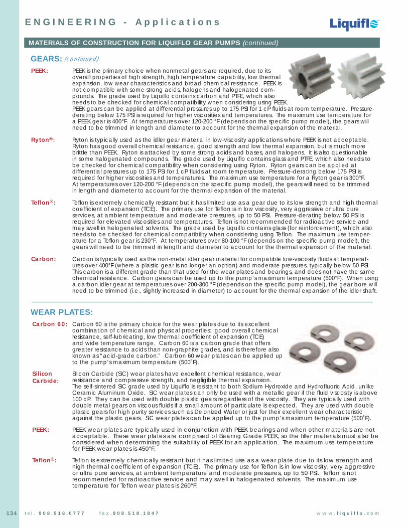
Chemical Processing Pumps
Chemical Processing Pumps
TM
TM
TM
134 t e l . 9 0 8 . 5 1 8 . 0 7 7 7 f a x . 9 0 8 . 5 1 8 . 1 8 4 7 w w w . l i q u i f l o . c o m
MATERIALS OF CONSTRUCTION FOR LIQUIFLO GEAR PUMPS (continued)
E N G I N E E R I N G - A p p l i c a t i o n s
GEARS: (continued)
PEEK: PEEK is the primary choice when nonmetal gears are required, due to its overall properties of high strength, high temperature capability, low thermalexpansion, low wear characteristics and broad chemical resistance. PEEK is not compatible with some strong acids, halogens and halogenated com-pounds. The grade used by Liquiflo contains carbon and PTFE, which also needs to be checked for chemical compatibility when considering using PEEK. PEEK gears can be applied at differential pressures up to 175 PSI for 1 cP fluids at room temperature. Pressure-derating below 175 PSI is required for higher viscosities and temperatures. The maximum use temperature for a PEEK gear is 400°F. At temperatures over 120-200 °F (depends on the specific pump model), the gears willneed to be trimmed in length and diameter to account for the thermal expansion of the material.
Ryton®: Ryton is typically used as the idler gear material in low-viscosity applications where PEEK is not acceptable.Ryton has good overall chemical resistance, good strength and low thermal expansion, but is much morebrittle than PEEK. Ryton is attacked by some strong acids and bases, and halogens. It is also questionable in some halogenated compounds. The grade used by Liquiflo contains glass and PTFE, which also needs tobe checked for chemical compatibility when considering using Ryton. Ryton gears can be applied atdifferential pressures up to 175 PSI for 1 cP fluids at room temperature. Pressure-derating below 175 PSI isrequired for higher viscosities and temperatures. The maximum use temperature for a Ryton gear is 300°F. At temperatures over 120-200 °F (depends on the specific pump model), the gears will need to be trimmed in length and diameter to account for the thermal expansion of the material.
Teflon®: Teflon is extremely chemically resistant but it has limited use as a gear due to its low strength and high thermalcoefficient of expansion (TCE). The primary use for Teflon is in low viscosity, very aggressive or ultra pureservices, at ambient temperature and moderate pressures, up to 50 PSI. Pressure-derating below 50 PSI isrequired for elevated viscosities and temperatures. Teflon is not recommended for radioactive service andmay swell in halogenated solvents. The grade used by Liquiflo contains glass (for reinforcement), which alsoneeds to be checked for chemical compatibility when considering using Teflon. The maximum use temper-ature for a Teflon gear is 230°F. At temperatures over 80-100 °F (depends on the specific pump model), thegears will need to be trimmed in length and diameter to account for the thermal expansion of the material.
Carbon: Carbon is typically used as the non-metal idler gear material for compatible low-viscosity fluids at temperat-ures over 400°F (where a plastic gear is no longer an option) and moderate pressures, typically below 50 PSI.This carbon is a different grade than that used for the wear plates and bearings, and does not have the samechemical resistance. Carbon gears can be used up to the pump’s maximum temperature (500°F). When usinga carbon idler gear at temperatures over 200-300 °F (depends on the specific pump model), the gear bore willneed to be trimmed (i.e., slightly increased in diameter) to account for the thermal expansion of the idler shaft.
WEAR PLATES:Carbon 60: Carbon 60 is the primary choice for the wear plates due to its excellent
combination of chemical and physical properties: good overall chemicalresistance, self-lubricating, low thermal coefficient of expansion (TCE) and wide temperature range. Carbon 60 is a carbon grade that offersgreater resistance to acids than non-graphite grades, and is therefore alsoknown as “acid-grade carbon.” Carbon 60 wear plates can be applied upto the pump’s maximum temperature (500˚F).
Silicon Silicon Carbide (SiC) wear plates have excellent chemical resistance, wearresistance and compressive strength, and negligible thermal expansion.The self-sintered SiC grade used by Liquiflo is resistant to both Sodium Hydroxide and Hydrofluoric Acid, unlikeCeramic Aluminum Oxide. SiC wear plates can only be used with a metallic gear if the fluid viscosity is above100 cP. They can be used with double plastic gears regardless of the viscosity. They are typically used withdouble metal gears on viscous fluids if a small amount of particulate is expected. They are used with doubleplastic gears for high purity services such as Deionized Water or just for their excellent wear characteristicagainst the plastic gears. SiC wear plates can be applied up to the pump’s maximum temperature (500˚F).
PEEK: PEEK wear plates are typically used in conjunction with PEEK bearings and when other materials are notacceptable. These wear plates are comprised of Bearing Grade PEEK, so the filler materials must also beconsidered when determining the suitability of PEEK for an application. The maximum use temperaturefor PEEK wear plates is 450°F.
Teflon®: Teflon is extremely chemically resistant but it has limited use as a wear plate due to its low strength and high thermal coefficient of expansion (TCE). The primary use for Teflon is in low viscosity, very aggressive or ultra pure services, at ambient temperature and moderate pressures, up to 50 PSI. Teflon is notrecommended for radioactive service and may swell in halogenated solvents. The maximum usetemperature for Teflon wear plates is 260°F.
Carbide:

Chemical Processing Pumps
Chemical Processing Pumps
TM
TM
TM
135t e l . 9 0 8 . 5 1 8 . 0 7 7 7 f a x . 9 0 8 . 5 1 8 . 1 8 4 7 w w w . l i q u i f l o . c o m
MATERIALS OF CONSTRUCTION FOR LIQUIFLO GEAR PUMPS (continued)
E N G I N E E R I N G - A p p l i c a t i o n s
BEARINGS:Carbon 60: Carbon 60 is the primary choice for the bearings due to its excellent combination of
chemical and physical properties: good overall chemical resistance, self-lubricating, low low thermal coefficient of expansion (TCE) and wide temperature range. In addition, carbon is hard, and has good compressive strength, heat transfer and wear prop-erties, making it an excellent bearing choice. This is the only available bearing material that can tolerate short periods of dry running. Carbon 60 is a carbon grade that offers greater resistance to acids than non-graphite grades, and is therefore also known as “acid-grade carbon.” Carbon 60bearings can be applied up to the pump’s maximum temperature (500°F). When using Carbon 60 bearings atelevated temperatures, the bearing bores may need to be trimmed (i.e., slightly increased in diameter) toaccount for the thermal expansion of the shafts.
Silicon Self-sintered Silicon Carbide (SiC) bearings have excellent chemical resistance, wear resistance and compressivestrength, and negligible thermal expansion. SiC bearings must be run against a hardened shaft. When usedagainst a TC-coated shaft (or a SiC shaft), the best life is achieved. SiC is extremely hard and has no tolerance for dry running. SiC bearings can be applied up to the pump’s maximum temperature (500°F). When using SiCbearings at elevated temperatures, the bearing bores may need to be trimmed (i.e., slightly increased indiameter) to account for the thermal expansion of the shafts.
PEEK: PEEK bearings have ~20% lower compressive strength than Carbon 60 bearings and are typically used whenother bearing materials are not acceptable. The grade used by Liquiflo is called Bearing Grade PEEK, whichcontains carbon fiber, graphite and PTFE. These filler materials increase lubrication and enable the bearing tohandle higher PV loads, but they must also be checked for chemical compatibility when considering using PEEK.The maximum use temperature for PEEK bearings is 350°F. When using PEEK bearings at elevated temperatures,the bearings may need to be trimmed to account for the thermal expansion of the material.
Teflon®: Teflon is extremely chemically resistant but it has limited use as a bearing material due to its low compressivestrength, high thermal expansion and tendency to cold flow under load. The primary use for Teflon is in lowviscosity, very aggressive or ultra pure services, at ambient temperature and moderate pressures, up to 50 PSI.Teflon is not recommended for radioactive service and may swell in halogenated solvents. The grade used byLiquiflo contains glass (for reinforcement), which also needs to be checked for chemical compatibility whenconsidering using Teflon. In addition, the glass filler can be abrasive to uncoated metal shafts, so hard-coatedshafts are recommended for thin fluids. The maximum use temperature for Teflon bearings is 180°F. When usingTeflon bearings at elevated temperatures, the bearings may need to be trimmed to account for the thermalexpansion of the material.
SHAFTS:316 SS & 316 SS drive and idler shafts are used when 316 SS housings are selected. Alloy-C
drive and idler shafts are used when Alloy-C or Alloy-20 housings are selected.Uncoated 316 SS and Alloy-C shafts are relatively soft and subject to contact wear at the bearing-shaft interfaces, especially at times when hydrodynamicfilm lubrication is lost or when PV loads are high. Since these conditions frequentlyoccur during normal pump operation, Liquiflo recommends using hard-coatedshafts (TC or CO) for virtually all applications. Hardened shafts will significantlyreduce the wear rate and extend pump life.
TC-Coated: 316 SS and Alloy-C shafts are available with Tungsten Carbide (TC) coating in the areas of the shaft that contactthe interior of the bearings (journal-bearing areas). TC-coated shafts are the primary choice for hardened shaftsbecause of the hardness, bond strength and wide temperature range of the coating material. Unlike the ceramiccoatings, the metal matrix allows the coating to expand and contract with the base metal of the shaft, so itdoesn’t tend to delaminate and crack like the ceramic. The metal matrix (Ni with a trace of Co) of the TCcoating can sometimes be a problem as it can be attacked by the fluid or act as a catalyst and cause thedecomposition of the fluid, as can occur with Hydrogen Peroxide service. TC-coated shafts can be applied up to the pump’s maximum temperature (500°F).
CO-Coated: 316 SS and Alloy-C shafts are available with Chrome Oxide (CO) coating in the areas of the shaft that contact theinterior of the bearings (journal-bearing areas). The ceramic CO is very chemically resistant but is not as hard asTungsten Carbide, and therefore not as wear resistant. For Hydrogen Peroxide service, CO-coated shafts shouldbe used in lieu of TC-coated shafts to prevent the catalytic decomposition of the fluid, which can produce H2and O2 gases. CO-coated shafts have limited temperature capability because the TCE of the ceramic coating ismuch lower than that of the base metal of the shaft. This can cause the ceramic coating to delaminate andcrack at high or low temperatures. The maximum use temperature for CO-coated shafts is 250°F.
Titanium, Titanium (Ti) shafts are used exclusively in Titanium pumps. Ti shafts are produced with Titanium Oxide (TO)coating in the areas of the shaft that contact the interior of the bearings (journal-bearing areas). TO-coatedshafts are typically used with Carbon 60 or Silicon Carbide bearings to provide an effective wear-resistantbearing-shaft combination. The maximum use temperature for TO-coated shafts is 250°F, due to thenegligible thermal expansion of the ceramic coating.
TO-Coated:
Alloy-C,Uncoated:
Carbide:
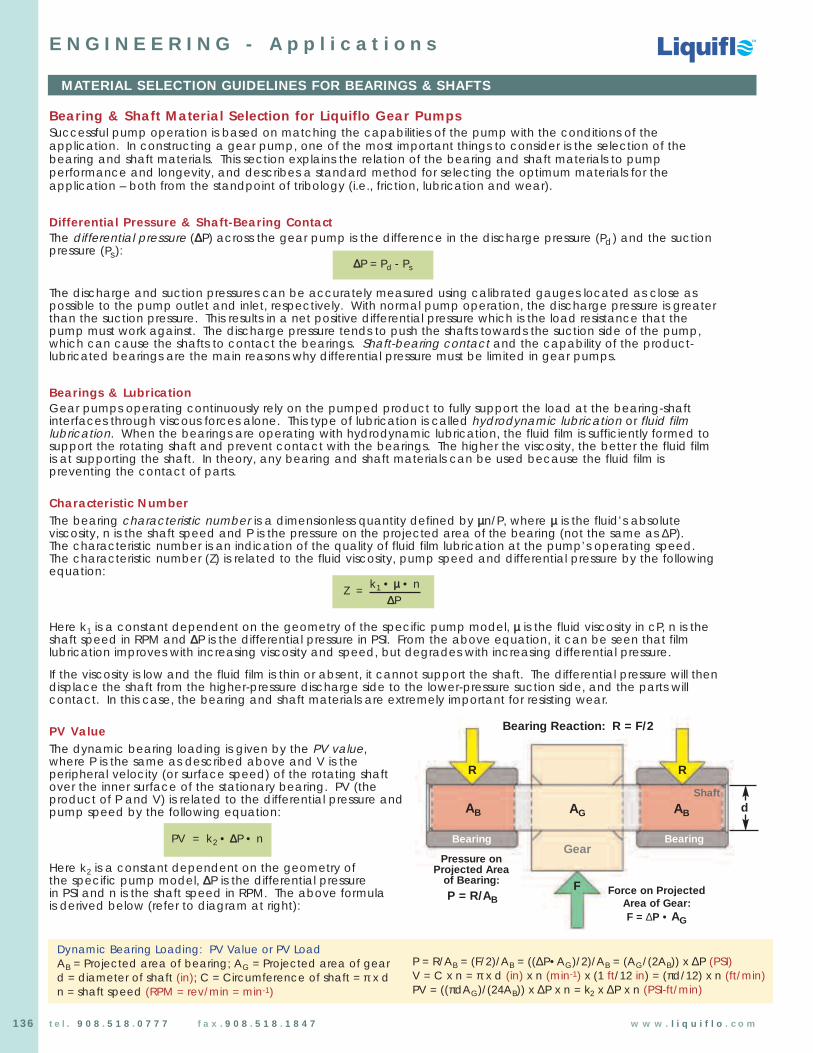
Chemical Processing Pumps
Chemical Processing Pumps
TM
TM
TM
136 t e l . 9 0 8 . 5 1 8 . 0 7 7 7 f a x . 9 0 8 . 5 1 8 . 1 8 4 7 w w w . l i q u i f l o . c o m
MATERIAL SELECTION GUIDELINES FOR BEARINGS & SHAFTS
E N G I N E E R I N G - A p p l i c a t i o n s
Bearing & Shaft Material Selection for Liquiflo Gear PumpsSuccessful pump operation is based on matching the capabilities of the pump with the conditions of theapplication. In constructing a gear pump, one of the most important things to consider is the selection of thebearing and shaft materials. This section explains the relation of the bearing and shaft materials to pumpperformance and longevity, and describes a standard method for selecting the optimum materials for theapplication – both from the standpoint of tribology (i.e., friction, lubrication and wear).
Differential Pressure & Shaft-Bearing ContactThe differential pressure (∆∆P) across the gear pump is the difference in the discharge pressure (Pd) and the suctionpressure (Ps):
The discharge and suction pressures can be accurately measured using calibrated gauges located as close aspossible to the pump outlet and inlet, respectively. With normal pump operation, the discharge pressure is greaterthan the suction pressure. This results in a net positive differential pressure which is the load resistance that thepump must work against. The discharge pressure tends to push the shafts towards the suction side of the pump,which can cause the shafts to contact the bearings. Shaft-bearing contact and the capability of the product-lubricated bearings are the main reasons why differential pressure must be limited in gear pumps.
Bearings & LubricationGear pumps operating continuously rely on the pumped product to fully support the load at the bearing-shaftinterfaces through viscous forces alone. This type of lubrication is called hydrodynamic lubrication or fluid filmlubrication. When the bearings are operating with hydrodynamic lubrication, the fluid film is sufficiently formed tosupport the rotating shaft and prevent contact with the bearings. The higher the viscosity, the better the fluid filmis at supporting the shaft. In theory, any bearing and shaft materials can be used because the fluid film ispreventing the contact of parts.
Characteristic NumberThe bearing characteristic number is a dimensionless quantity defined by µµn/P, where µµ is the fluid’s absoluteviscosity, n is the shaft speed and P is the pressure on the projected area of the bearing (not the same as ∆P). The characteristic number is an indication of the quality of fluid film lubrication at the pump’s operating speed.The characteristic number (Z) is related to the fluid viscosity, pump speed and differential pressure by the followingequation:
Here k1 is a constant dependent on the geometry of the specific pump model, µµ is the fluid viscosity in cP, n is theshaft speed in RPM and ∆∆P is the differential pressure in PSI. From the above equation, it can be seen that filmlubrication improves with increasing viscosity and speed, but degrades with increasing differential pressure.
If the viscosity is low and the fluid film is thin or absent, it cannot support the shaft. The differential pressure will thendisplace the shaft from the higher-pressure discharge side to the lower-pressure suction side, and the parts willcontact. In this case, the bearing and shaft materials are extremely important for resisting wear.
PV ValueThe dynamic bearing loading is given by the PV value, where P is the same as described above and V is theperipheral velocity (or surface speed) of the rotating shaftover the inner surface of the stationary bearing. PV (theproduct of P and V) is related to the differential pressure andpump speed by the following equation:
Here k2 is a constant dependent on the geometry ofthe specific pump model, ∆∆P is the differential pressure in PSI and n is the shaft speed in RPM. The above formula is derived below (refer to diagram at right):
∆∆P = Pd - Ps
PV = k2 • ∆∆P • n
P = R/AB = (F/2)/AB = ((∆P•AG)/2)/AB = (AG/(2AB)) x ∆P (PSI)V = C x n = π x d (in) x n (min-1) x (1 ft/12 in) = (πd/12) x n (ft/min)PV = ((πdAG)/(24AB)) x ∆P x n = k2 x ∆P x n (PSI-ft/min)
AG ABAB
Gear
Shaft
Bearing Bearing
F
R R
Bearing Reaction: R = F/2
Force on ProjectedArea of Gear:F = ∆P • AG
Pressure onProjected Area
of Bearing:
P = R/AB
Dynamic Bearing Loading: PV Value or PV LoadAB = Projected area of bearing; AG = Projected area of geard = diameter of shaft (in); C = Circumference of shaft = π x dn = shaft speed (RPM = rev/min = min-1)
d
Z = k1 • µµ • n∆∆P
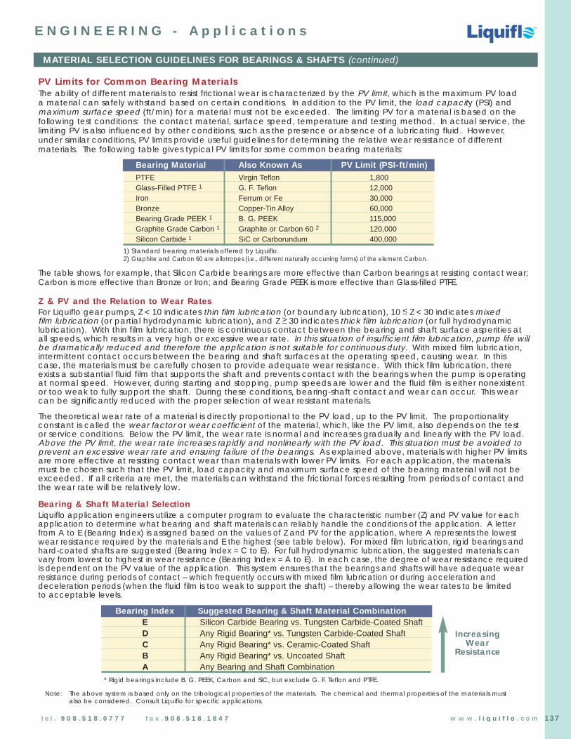
PV Limits for Common Bearing MaterialsThe ability of different materials to resist frictional wear is characterized by the PV limit, which is the maximum PV loada material can safely withstand based on certain conditions. In addition to the PV limit, the load capacity (PSI) andmaximum surface speed (ft/min) for a material must not be exceeded. The limiting PV for a material is based on thefollowing test conditions: the contact material, surface speed, temperature and testing method. In actual service, thelimiting PV is also influenced by other conditions, such as the presence or absence of a lubricating fluid. However,under similar conditions, PV limits provide useful guidelines for determining the relative wear resistance of differentmaterials. The following table gives typical PV limits for some common bearing materials:
The table shows, for example, that Silicon Carbide bearings are more effective than Carbon bearings at resisting contact wear;Carbon is more effective than Bronze or Iron; and Bearing Grade PEEK is more effective than Glass-filled PTFE.
Z & PV and the Relation to Wear RatesFor Liquiflo gear pumps, Z < 10 indicates thin film lubrication (or boundary lubrication), 10 < Z < 30 indicates mixed film lubrication (or partial hydrodynamic lubrication), and Z > 30 indicates thick film lubrication (or full hydrodynamiclubrication). With thin film lubrication, there is continuous contact between the bearing and shaft surface asperities atall speeds, which results in a very high or excessive wear rate. In this situation of insufficient film lubrication, pump life willbe dramatically reduced and therefore the application is not suitable for continuous duty. With mixed film lubrication,intermittent contact occurs between the bearing and shaft surfaces at the operating speed, causing wear. In thiscase, the materials must be carefully chosen to provide adequate wear resistance. With thick film lubrication, thereexists a substantial fluid film that supports the shaft and prevents contact with the bearings when the pump is operatingat normal speed. However, during starting and stopping, pump speeds are lower and the fluid film is either nonexistentor too weak to fully support the shaft. During these conditions, bearing-shaft contact and wear can occur. This wearcan be significantly reduced with the proper selection of wear resistant materials.
The theoretical wear rate of a material is directly proportional to the PV load, up to the PV limit. The proportionalityconstant is called the wear factor or wear coefficient of the material, which, like the PV limit, also depends on the testor service conditions. Below the PV limit, the wear rate is normal and increases gradually and linearly with the PV load.Above the PV limit, the wear rate increases rapidly and nonlinearly with the PV load. This situation must be avoided toprevent an excessive wear rate and ensuing failure of the bearings. As explained above, materials with higher PV limitsare more effective at resisting contact wear than materials with lower PV limits. For each application, the materialsmust be chosen such that the PV limit, load capacity and maximum surface speed of the bearing material will not beexceeded. If all criteria are met, the materials can withstand the frictional forces resulting from periods of contact andthe wear rate will be relatively low.
Bearing & Shaft Material SelectionLiquiflo application engineers utilize a computer program to evaluate the characteristic number (Z) and PV value for eachapplication to determine what bearing and shaft materials can reliably handle the conditions of the application. A letterfrom A to E (Bearing Index) is assigned based on the values of Z and PV for the application, where A represents the lowestwear resistance required by the materials and E the highest (see table below). For mixed film lubrication, rigid bearings andhard-coated shafts are suggested (Bearing Index = C to E). For full hydrodynamic lubrication, the suggested materials canvary from lowest to highest in wear resistance (Bearing Index = A to E). In each case, the degree of wear resistance requiredis dependent on the PV value of the application. This system ensures that the bearings and shafts will have adequate wearresistance during periods of contact – which frequently occurs with mixed film lubrication or during acceleration anddeceleration periods (when the fluid film is too weak to support the shaft) – thereby allowing the wear rates to be limited to acceptable levels.
Chemical Processing Pumps
Chemical Processing Pumps
TM
TM
TM
137
MATERIAL SELECTION GUIDELINES FOR BEARINGS & SHAFTS (continued)
E N G I N E E R I N G - A p p l i c a t i o n s
Bearing Material Also Known As PV Limit (PSI-ft/min)PTFE Virgin Teflon 1,800Glass-Filled PTFE 1 G. F. Teflon 12,000Iron Ferrum or Fe 30,000Bronze Copper-Tin Alloy 60,000Bearing Grade PEEK 1 B. G. PEEK 115,000Graphite Grade Carbon 1 Graphite or Carbon 60 2 120,000Silicon Carbide 1 SiC or Carborundum 400,000
1) Standard bearing materials offered by Liquiflo.2) Graphite and Carbon 60 are allotropes (i.e., different naturally occurring forms) of the element Carbon.
IncreasingWear
Resistance
* Rigid bearings include B. G. PEEK, Carbon and SiC, but exclude G. F. Teflon and PTFE.
Note: The above system is based only on the tribological properties of the materials. The chemical and thermal properties of the materials must also be considered. Consult Liquiflo for specific applications.
Bearing Index Suggested Bearing & Shaft Material CombinationE Silicon Carbide Bearing vs. Tungsten Carbide-Coated ShaftD Any Rigid Bearing* vs. Tungsten Carbide-Coated ShaftC Any Rigid Bearing* vs. Ceramic-Coated ShaftB Any Rigid Bearing* vs. Uncoated ShaftA Any Bearing and Shaft Combination
t e l . 9 0 8 . 5 1 8 . 0 7 7 7 f a x . 9 0 8 . 5 1 8 . 1 8 4 7 w w w . l i q u i f l o . c o m

Chemical Processing Pumps
Chemical Processing Pumps
TM
TM
TM
138 t e l . 9 0 8 . 5 1 8 . 0 7 7 7 f a x . 9 0 8 . 5 1 8 . 1 8 4 7 w w w . l i q u i f l o . c o m
E N G I N E E R I N G - A p p l i c a t i o n s
Determination of Pump Performance When Handling Viscous LiquidsThe performance of centrifugal pumps is affected when handling viscous liquids. A marked increase in brake horsepower,a reduction in head, and some reduction in capacity occur with moderate and high viscosities.
Graph 1 and Graph 2 on the following pages provide a means of determining the performance of a conventional centrifugalpump handling a viscous liquid when its performance on water is known. Graph 1 and Graph 2 can also be used as an aid inselecting a pump for a given application. The values shown in Graph 2 are averages of tests from conventional single stagepumps of 2” to 8” size, handling petroleum oils. The values shown in Graph 1 were prepared from other tests on several smallerpumps (1” and below). Therefore, the correction curves are not exact for any particular pump.
Limitations on use of Viscous Liquids Performance Correction ChartUse only for pumps of conventional hydraulic design, in the normal operating range, with open or closed impellers. Do not usefor mixed flow or axial flow pumps, or for pumps of special hydraulic design for either viscous or non-uniform liquids. Use onlywhere adequate NPSH is available in order to avoid cavitation.
Use only Newtonian (uniform liquids). Gels, slurries, paper stock and other non-uniform liquids may produce widely varying resultsdepending on the particular characteristics of the liquids.
Symbols and Definitions Used in Determination of Pump Performance When Handling Viscous Liquids
Qvis = Viscous capacity in GPM – The capacity when pumping a viscous fluid.
Hvis = Viscous head in feet – The head when pumping a viscous fluid.
nvis = Viscous efficiency in percent – The efficiency when pumping a viscous fluid.
bhpvis = Viscous brake horsepower – The horsepower required by the pump for the viscous conditions.
Qw = Water capacity in GPM – The capacity when pumping water.
Hw = Water head in feet – The head when pumping water.
nw = Water efficiency in percent – The efficiency when pumping water.
SG = Specific gravity.
CQ = Capacity correction factor.
CH = Head correction factor.
Cn = Efficiency correction factor.
QNW = Water capacity in which maximum efficiency is obtained.
The following equations are used for determining the viscous performance when thewater performance of the pump is known:
Qvis = CQ x QwHvis = CH x Hwnvis = Cn x nw
bhpvis =Qvis x Hvis x SG
3960 x nvis
The following equations are used for approximating the water performance when thedesired viscous capacity and head are given:
Qw =Qvis
CQ
Hw =Hvis
CH
CQ, CH and Cn, are determined from Graph 1 and Graph 2 which are based on water performance. Graph 1 is to be used for small pumps having capacityat best efficiency point (BEP) of less than 100 GPM (water performance).
The values of CQ and CH are found from Graph 1 and Graph 2 usingQvis and Hvis.
CENTRIFUGAL PUMP SELECTION FOR VISCOUS SERVICE

Chemical Processing Pumps
Chemical Processing Pumps
TM
TM
TM
139t e l . 9 0 8 . 5 1 8 . 0 7 7 7 f a x . 9 0 8 . 5 1 8 . 1 8 4 7 w w w . l i q u i f l o . c o m
E N G I N E E R I N G - A p p l i c a t i o n s
Flow = Qvis = 53 gpmHead = Hvis = 50 feet
Viscosity = 200 SSUSpecific Gravity = 0.95
Selecting a Pump for a Given Head-Capacity-Viscosity ConditionGiven the desired capacity and head of the viscous liquid to be pumped, and the viscosity and specific gravity at the pumpingtemperature, Graph 1 or Graph 2 can be used to find approximate equivalent capacity and head when pumping water.
Enter appropriate chart with the desired viscous capacity, (Qvis) and proceed upward to the desired viscous head (Hvis) in feet of liquid. For multi-stage pumps use head per stage. Proceed horizontally (either left or right) to the fluid viscosity, and then go upward to the correction curves. Divide the viscous capacity (Qvis) by the capacity correction factor (CQ) to get theapproximate equivalent to water capacity (Qw). Divide the viscous head (Hvis) by the head correction factor (CH) from thecurve marked “1.0 x QNW” to get the approximate equivalent water head (Hw) at BEP. Using the new equivalent water headcapacity point, select a pump in the usual manner. The viscous efficiency (nvis) and the viscous brake horsepower (bhpvis) maythen be calculated.
Example 1:
Select a pump to deliver 750 gpm at 100 feet total head of aliquid having a viscosity 1000 SSU and a specific gravity of 0.90.
Enter Graph 2 at 750 gpm, go up to 100 feet head, over to 1000 SSU and then up to the correction factors:
CQ = = 0.95CH = = 0.92 (for 1.0 x QNW)Cn = = 0.64
Qw = =750
= 790 gpm0.95
Hw = =100
= 109 feet of head0.92
Select a pump with a water capacity of 790 gpm at 109 feet of head. The selection should be at or close to the maximum efficiency point for water performance. If the pump selected has an efficiency on water of 81 percentat 790 gpm, then the efficiency for the viscous liquid will be as follows:
nvis = = 0.64 x 81% = 51.8%
The brake horsepower for pumping the viscous liquid will be:
bhpvis = =750 x 100 x 0.90
= 32.9 hp3960 x 0.518
Example 2:
Select a pump to deliver 53 gpm at 50 feet total head of aliquid having a viscosity 200 SSU and a specific gravity of 0.95.
Enter Graph 1 at 53 gpm, go up to 50 feet head, over to 200 SSU and then up to the correction factors:
CQ = 0.88CH = 1.0Cn = 0.67
Qw = =53
= 60 gpm0.88
Hw = =50
= 50 feet of head1.0
Select a pump with a water capacity of 60 gpm at 50 feet of head.
Flow = Qvis = 750 gpmHead = Hvis = 100 feet
Viscosity = 1000 SSUSpecific Gravity = 0.90
CENTRIFUGAL PUMP SELECTION FOR VISCOUS SERVICE (continued)
Qvis
CQ
Hvis
CH
Cn x nw
Qvis x Hvis x SG
3960 x nvis
Qvis
CQ
Hvis
CH
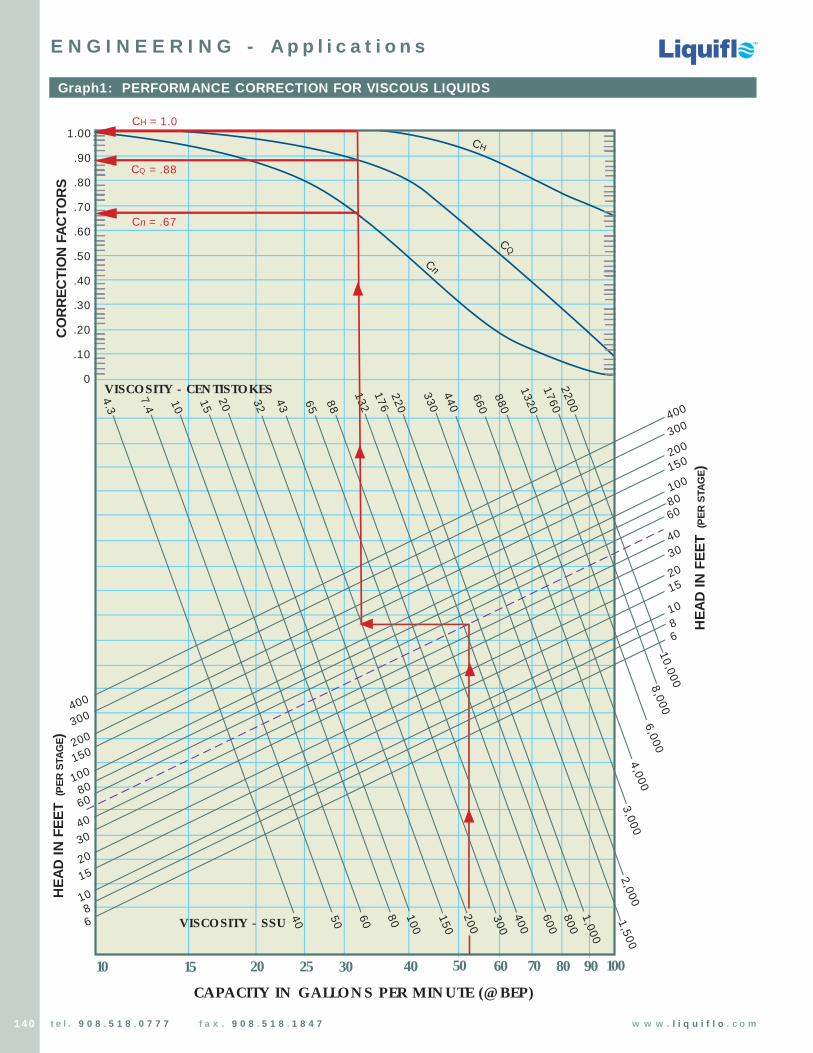
Chemical Processing Pumps
Chemical Processing Pumps
TM
TM
TM
140 t e l . 9 0 8 . 5 1 8 . 0 7 7 7 f a x . 9 0 8 . 5 1 8 . 1 8 4 7 w w w . l i q u i f l o . c o m
Graph1: PERFORMANCE CORRECTION FOR VISCOUS LIQUIDS
25201510
HE
AD
IN F
EE
T (
PE
R S
TAG
E)
30
400
300
200
150
100
8060
40
30
2015
10
68
400
300
200
150
1008060
40
30
20
15
10
68
10,0008,0006,000
4,0003,000
2,0001,500
1,000
800
600
400
300
200
150
100
80605040
40 50 60 70 80 90 100
VISCOSITY - SSU
CAPACITY IN GALLONS PER MINUTE (@ BEP)
1.00
.90
.80
.70
.60
.50
.40
.30
.20
.10
0VISCOSITY - CENTISTOKES 2200
1760
1320
880
660
440
330
220
13288654332
201510
7.4
4.3
CH
CQ
Cn
CO
RR
EC
TIO
N F
AC
TO
RS
176
Cn = .67
CQ = .88
CH = 1.0
HE
AD
IN F
EE
T (
PE
R S
TAG
E)
E N G I N E E R I N G - A p p l i c a t i o n s

Chemical Processing Pumps
Chemical Processing Pumps
TM
TM
TM
141t e l . 9 0 8 . 5 1 8 . 0 7 7 7 f a x . 9 0 8 . 5 1 8 . 1 8 4 7 w w w . l i q u i f l o . c o m
Graph 2: PERFORMANCE CORRECTION FOR VISCOUS LIQUIDS
6421
HE
AD
IN F
EE
T (
PE
R S
TAG
E)
8
600400300200
100806040302015
10 15 20 40 60 80 100CAPACITY IN 100 GPM
1.00
.90
.80
.70
.60
.50
.40
.30
.20
VISCOSITY - CENTISTOKES
2200
1760
1320
880
660
440
330
220
13288654332201510
CQ
Cn
CO
RR
EC
TIO
N F
AC
TO
RS
176
150
3300
600400300200
100806040302015
1.00
.90
.80
.70
.60
EF
FIC
IEN
CY
& C
AP
AC
ITY
HE
AD
VISCOSITY - SSU
CH
— 0.6 x QNW
— 0.8 x QNW
— 1.0 x QNW
— 1.2 x QNW
150
8,000
6,000
4,000
3,000
2,000
1,500
1,000
800
600
400
300
150
100
806040 200
15,000
10,000
HE
AD
IN F
EE
T (
PE
R S
TAG
E)
Cn = .64
CQ = .95
CH = .92 (for 1.0 x QNW)
Cn
& C
Q C
H
E N G I N E E R I N G - A p p l i c a t i o n s

Chemical Processing Pumps
Chemical Processing Pumps
TM
TM
TM
142 t e l . 9 0 8 . 5 1 8 . 0 7 7 7 f a x . 9 0 8 . 5 1 8 . 1 8 4 7 w w w . l i q u i f l o . c o m
NPSHAIn order for pumps to function properly, there must be enough suction pressure available to force the fluid into the pump’s inlet.In addition, the fluid must be kept in a liquid state or cavitation will occur. The following four parameters must be known in orderto calculate the net positive suction head available (NPSHA) for a pumping system:
1. PB = Absolute Barometric Pressure in Feet of Liquid (+), or p = Absolute Pressure on Surface of Liquid in Closed Supply Tank in Feet of Liquid (+)
2. LH = Static Suction Head (+), or Ls = Suction Lift (–)3. hf = Friction Loss in Suction Line (–)4. Vp = Vapor Pressure of Liquid (–)
The NPSHA is the algebraic sum of these four terms. Figures A thru D below, illustrate how to calculate the NPSHA for fourcommon pumping situations.
Requirement: NPSHA > NPSHRThe net positive suction head required (NPSHR) by a pump is determined by testing and is usually specified at a particularoperating speed and based on pumping water. A requirement for all pumps is that the NPSHA must be greater than the NPSHR.Failure to meet this condition will result in cavitation. The symptoms of cavitation are decreased flow, increased vibrations andnoise from the pump. Cavitation results when the fluid vaporizes because there is insufficient pressure available to keep the fluidin a liquid state. This condition must be avoided when running a pump because it will cause rapid wear and can damage thepump in a very short time.
Example: An application requires that 180°F water be pumped at 3 GPM with a gear pump at sea level. The supply tank is open to the atmosphere and the surface of the liquid in the tank will be no more than 6 ft below the pump’s inlet. Assume that the friction losses in the suction line are equivalent to 2 ft of static head. The vapor pressure of water is about 380 mmHg at the pumping temperature.
a: What is the NPSHA for the pumping system?
Answer: Since the tank is aerated and is located at sea level, the Absolute Barometric Pressure (PB) is about 14.7 PSI or 34 ft. When the liquid level is near the bottom of the tank, the pump must be able to lift the water 6 ft, so the worst-case Suction Lift (Ls) is 6 ft. The Friction Loss (hf ) in the suction line is given as 2 ft. The Vapor Pressure (Vp) of the hot water is equivalent to 17 ft. Therefore,
NPSHA = PB – Ls – hf – Vp = 34 ft – 6 ft – 2 ft – 17 ft = 34 ft – 25 ft = 9 ft
b: What pumping situation is described in Part a?
Answer: Situation A (see figure below).
c: What must the gear pump’s NPSHR be to successfully handle the application?
Answer: The NPSHA for a pumping system should be at least a couple of feet more than the NPSHR by the pump. This will provide a safety margin to account for any variation in the system parameters. Therefore, the NPSHR by the pump should be about 7 ft or less.
CALCULATION OF SYSTEM NPSHA
E N G I N E E R I N G - A p p l i c a t i o n s
p
PB
LS
LH
PB
LH
p
LS
CALCULATIONof SYSTEMNPSHAfor COMMONPUMPINGSITUATIONS
NPSHA = PB – LS – hf – Vp
A. Suction Supply Open to Atmosphere B. Closed Suction Supplywith Suction Lift with Suction Lift
C. Suction Supply Open to Atmosphere D. Closed Suction Supply with Suction Head with Suction Head
NPSHA = p – LS – hf – Vp
NPSHA = PB + LH – hf – Vp NPSHA = p + LH – hf – Vp
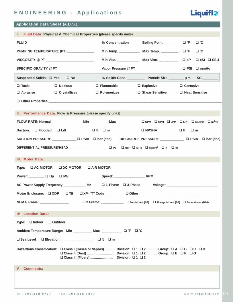
Chemical Processing Pumps
Chemical Processing Pumps
TM
TM
TM
143t e l . 9 0 8 . 5 1 8 . 0 7 7 7 f a x . 9 0 8 . 5 1 8 . 1 8 4 7 w w w . l i q u i f l o . c o m
I. Fluid Data: Physical & Chemical Properties (please specify units)
FLUID_______________________________________ % Concentration _______ Boiling Point__________ q ˚F q ˚C
PUMPING TEMPERATURE (PT) ________________ Min Temp. ____________ Max Temp. ___________ q ˚F q ˚C
VISCOSITY @ PT ______________________________ Min Visc. _____________ Max Visc. ____________ q cP q cSt q SSU
SPECIFIC GRAVITY @ PT ______________________ Vapor Pressure @ PT _________________________ q PSI q mmHg
Suspended Solids: q Yes q No % Solids Conc. __________ Particle Size _________ µ m SG _________
q Toxic q Noxious q Flammable q Explosive q Corrosive
q Abrasive q Crystallizes q Polymerizes q Shear Sensitive q Heat Sensitive
q Other Properties _____________________________________________________________________________________________________
II. Performance Data: Flow & Pressure (please specify units)
FLOW RATE: Normal _________________ Min __________ Max __________ qGPM q GPH q LPM q LPH qmL/min qm3/hr
Suction: q Flooded q Lift ______________ q ft q m q NPSHA ___________ q ft q m
SUCTION PRESSURE ______________ q PSIA q bar (abs) DISCHARGE PRESSURE ______________ q PSIA q bar (abs)
DIFFERENTIAL PRESSURE/HEAD ______________________ q PSI q bar q MPa q kg/cm2 q ft q m
III. Motor Data:
Type: qAC MOTOR qDC MOTOR qAIR MOTOR
Power: _________ q Hp q kW Speed: __________________ RPM
AC Power Supply Frequency _____________ Hz q 1-Phase q 3-Phase Voltage: ______________________________
Motor Enclosure: qODP q TE q XP-“T” Code __________ qOther _______________________________________________
NEMA Frame: _________________ IEC Frame: _____________ q FootMount (B3) q Flange Mount (B5) q Face Mount (B14)
IV. Location Data:
Type: q Indoor qOutdoor
Ambient Temperature Range: Min ___________ Max ___________ q ˚F q ˚C
q Sea Level q Elevation ___________________ q ft qm
Hazardous Classification: qClass I (Gases or Vapors) ......... Division: q 1 q 2 .......... Group: qA qB qC qD qClass II (Dust) ............................ Division: q 1 q 2 .......... Group: q E q F qG qClass III (Fibers) ........................ Division: q 1 q 2
V. Comments:
Application Data Sheet (A.D.S.)
E N G I N E E R I N G - A p p l i c a t i o n s

Chemical Processing Pumps
Chemical Processing Pumps
TM
TM
TM
144 t e l . 9 0 8 . 5 1 8 . 0 7 7 7 f a x . 9 0 8 . 5 1 8 . 1 8 4 7 w w w . l i q u i f l o . c o m
ENGINEERING FORMULAS
E N G I N E E R I N G - F o r m u l a s
1 TEMPERATURE CONVERSIONS:
1a) ˚F = (1.8 x ˚C) + 32
1b) ˚C = 0.556 x ( ˚F – 32)
2 FLUID HORSEPOWER (FHP):
2a) FHP = ∆P [PSI] x Q [GPM]
1714
2b) FHP = H [ft] x Q [GPM] x SG3960
3 BRAKE HORSEPOWER (BHP):
3a) BHP = FHP = ∆P [PSI] x Q [GPM]
E 1714 x E
3b) BHP = FHP = H [ft] x Q [GPM] x SGE 3960 x E
4 PUMP EFFICIENCY (E):
4a) E = Hydraulic Output Power = FHP Total Input Power BHP
5 MECHANICAL POWER (Pm ):
5a) Pm [Hp] = T [in-lbs] x n [RPM]
63,025
5b) Pm [kW] = T [in-lbs] x n [RPM]
84,484
6 SPECIFIC SPEED (ns) for Centrifugal Pumps:
6a) ns = n [RPM] x Q [GPM]
(H [ft] ) 3/4
7 AFFINITY LAWS for Centrifugal Pumps:
7a) Q 1 = n1D1
Q 2 n2D2
7b) H 1 = n12D1
2
H 2 n22D2
2
7c) P 1 = n13D1
3
P 2 n23D2
3
8 Centrifugal Pump Operating at Low Capacity:
8a) Temperature Rise: ∆T [˚F ] = H [ft] 1778 Cp[ Btu/lb-˚F ]
xE–1
8b) Minimum Flow: Qmin [GPM] = 3960 x BHPSG (778 Cp[Btu/lb-˚F ] ∆T [˚F ] + H [ft])
These basic formulas are used for the design, analysisand operation of gear andcentrifugal pumps.
(NPSHR formula has the same format as formula 7b.)
Parameters:
FHP = Fluid HorsepowerBHP = Brake Horsepower∆P = Differential PressureQ = Flow RateQmin = Minimum Flow RateT = Torquen = Speedns = Specific SpeedH = Total HeadE = EfficiencyP = PowerPm = Mechanical PowerD = Impeller Diameter∆T = Temperature RiseCp = Specific Heat of LiquidSG = Specific Gravity of LiquidAi = Pipe Inner Cross-sectional Areadi = Pipe Inner DiameterDD = Displacementg = Gravitational Constantδ = Density of Liquidδw = Density of Waterv = Velocity of Liquidp = Pressure, staticz = Elevations = Suctiond = DischargeV = VoltageI = CurrentPF = Power Factor
Note: PF = Power Factor = Ratio of Real Power to Apparent Power = Cos θ = Cosine of phase-shift angle(θ ) between voltage and current sine waves.
Units:˚F = Degrees Fahrenheit˚C = Degrees CelsiusPSI = Pounds per Square InchGPM = Gallons per MinuteRPM = Revolutions per Minutein-lbs = Inch-Poundsft = FeetHp = HorsepowerkW = KilowattsBtu = British Thermal UnitcSt = CentistokescP = CentipoisesVdc = DC VoltsVr ms = AC VoltsAdc = DC AmperesAr ms = AC Amperes

Chemical Processing Pumps
Chemical Processing Pumps
TM
TM
TM
145t e l . 9 0 8 . 5 1 8 . 0 7 7 7 f a x . 9 0 8 . 5 1 8 . 1 8 4 7 w w w . l i q u i f l o . c o m
ENGINEERING FORMULAS (continued)
E N G I N E E R I N G - F o r m u l a s
9 Flow Rate (Q) in terms of Fluid Velocity (v) and Pipe Dimensions
9a) Q = vAi
9b) Q = π/4 x vdi2 = 0.785 vdi
2
10 Displacement Rate (DD ) of Rotary Pumps
10a) DD [gal/rev] = Q [GPM]
n [RPM]
11 Total Head (H)
11a) Total Dynamic Head: Hdynamic = (vd2 – vs2 )
11b) Total Static Head: Hstatic = (pd – ps) + (zd – zs)δ
11c) H = Hdynamic + Hstatic = (vd2 – vs2) + (pd – ps) + (zd – zs)δ
12 Relation Between Static Head and Pressure
12a) H [ft] = p [PSI] x 2.31SG
12b) p [PSI] = H [ft] x SG2.31
13 Relation between Kinematic and Absolute Viscosity
13a) Kinematic Viscosity [cSt] = Absolute Viscosity [cP]
SG
14 Relation between Density and Specific Gravity
14a) SG = δδw
14b) δ = δw x SG
15 Efficiency (E) of DC Motors
15a) E = Mechanical Output Power = Pm[Hp] x 746Electrical Input Power V [Vdc] x I [Adc]
16 Efficiency (E) of Single-Phase AC Motors
16a) E = Mechanical Output Power = Pm[Hp] x 746Electrical Input Power V [Vr ms] x I [Arms] x PF
17 Efficiency (E) of Three-Phase AC Motors
17a) E = Mechanical Output Power = Pm[Hp] x 746Electrical Input Power V [Vr ms] x I [Arms] x PF x √3
These basic formulas are used for the design, analysisand operation of gear andcentrifugal pumps.
2g
2g
Parameters:
FHP = Fluid HorsepowerBHP = Brake Horsepower∆P = Differential PressureQ = Flow RateQmin = Minimum Flow RateT = Torquen = Speedns = Specific SpeedH = Total HeadE = EfficiencyP = PowerPm = Mechanical PowerD = Impeller Diameter∆T = Temperature RiseCp = Specific Heat of LiquidSG = Specific Gravity of LiquidAi = Pipe Inner Cross-sectional Areadi = Pipe Inner DiameterDD = Displacementg = Gravitational Constantδ = Density of Liquidδw = Density of Waterv = Velocity of Liquidp = Pressure, staticz = Elevations = Suctiond = DischargeV = VoltageI = CurrentPF = Power Factor
Note: PF = Power Factor = Ratio of Real Power to Apparent Power = Cos θ = Cosine of phase-shift angle(θ ) between voltage and current sine waves.
Units:˚F = Degrees Fahrenheit˚C = Degrees CelsiusPSI = Pounds per Square InchGPM = Gallons per MinuteRPM = Revolutions per Minutein-lbs = Inch-Poundsft = FeetHp = HorsepowerkW = KilowattsBtu = British Thermal UnitcSt = CentistokescP = CentipoisesVdc = DC VoltsVr ms = AC VoltsAdc = DC AmperesAr ms = AC Amperes
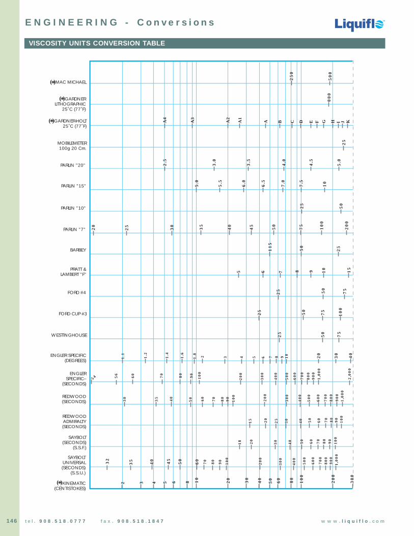
Chemical Processing Pumps
Chemical Processing Pumps
TM
TM
TM
146 t e l . 9 0 8 . 5 1 8 . 0 7 7 7 f a x . 9 0 8 . 5 1 8 . 1 8 4 7 w w w . l i q u i f l o . c o m
VISCOSITY UNITS CONVERSION TABLE
E N G I N E E R I N G - C o n v e r s i o n s
32
40 45
50
70
80
90
100
200
300
400
500
600
700
800
900
1,0
00
35
300
400
500
600
700
800
900
200
30
40 50 70 80
90
100
20
15
25 60
30
40 50 70 80
90
100
20
18
1,0
00
60
100
90
50 80
7060
40
35
30
300
400
500
600
700
800
900
200
1,0
00
2,0
00
54 56
60 70 80
90
100
3 4 5 7 8 9 1021.81.61.4
1.2
1.1
60
20
30 40
50 75
25
25 50
75
10
0
25 7550
8 159 106 75
50
11
5
25
75
50
10
0
20
0
45
4035
25
50
5.5
7.5
5.0
10
6.0
6.5
7.0
4.5
4.0
3.5
5.0
3.0
2.5
25
00
05
00
25
0C D E F G H I J KBAA
1
A2
A4
A3
6
2 3 4 5 6 8 10
20 30
40
50 60 80
10
0
20
0
30
0
MAC MICHAEL( )*
GARDNERLITHOGRAPHIC
25˚C (77˚F)
( )*
MOBILEMETER100g 20 Cm.
PARLIN "20"
PARLIN "15"
PARLIN "10"
PARLIN "7"
BARBEY
PRATT &LAMBERT "F"
FORD #4
FORD CUP #3
WESTINGHOUSE
ENGLER SPECIFIC(DEGREES)
ENGLERSPECIFIC–
(SECONDS)
REDWOOD(SECONDS)
REDWOODADMIRALTY(SECONDS)
SAYBOLT(SECONDS)
(S.S.F.)
SAYBOLTUNIVERSAL(SECONDS)
(S.S.U.)
KINEMATIC(CENTISTOKES)
GARDNER-HOLT25˚C (77˚F)
( )*
( )*
25 30
20
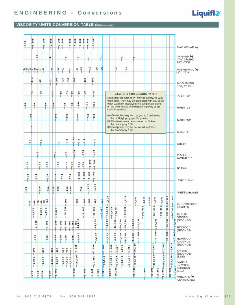
Chemical Processing Pumps
Chemical Processing Pumps
TM
TM
TM
147t e l . 9 0 8 . 5 1 8 . 0 7 7 7 f a x . 9 0 8 . 5 1 8 . 1 8 4 7 w w w . l i q u i f l o . c o m
VISCOSITY UNITS CONVERSION TABLE (continued)
E N G I N E E R I N G - C o n v e r s i o n s
MAC MICHAEL ( )*
GARDNERLITHOGRAPHIC25˚C (77˚F)
( )*
MOBILEMETER100g 20 Cm.
PARLIN "20"
PARLIN "15"
PARLIN "10"
PARLIN "7"
BARBEY
PRATT &LAMBERT "F"
FORD #4
FORD CUP #3
WESTINGHOUSE
ENGLER SPECIFIC(DEGREES)
ENGLERSPECIFIC–(SECONDS)
REDWOOD(SECONDS)
REDWOODADMIRALTY(SECONDS)
SAYBOLT(SECONDS)(S.S.F.)
SAYBOLTUNIVERSAL(SECONDS)(S.S.U.)
KINEMATIC(CENTISTOKES)
20
80
15
10
0
30
40
60
Z2
S U V W X ZY Z1
QPONL M
15
0
20
0
Z4
Z3
Z5
TR Z6
3.
2.
1.
00 4.
0 5. 6.
1,0
00
2,0
00
2,5
00
10
,00
0
75
0
8,0
00
3,0
00
7,0
00
5,0
00
6,0
00
1,5
00
4,0
00
30
0
40
0
15
0
20
0
12
5
75
10
0
37
.5
50
50
30
25
20
10
15
7.5
40
70
20
0
50
0
10
0
30
0
75
0
95
0
30
0
2.4
5 4.3
3.7
5
3.3
1.5
10
15
75
10
0
15
0
20
0
50
25
20
0
30
0
40
0
50
0
15
0
10
0
70
08
00
1,0
00
1,2
00
30
0
40
0
50
0
70
0
20
0
15
0
1,0
00
1,2
00
1,5
00
1,7
00
20
0
30
0
40
05
00
15
0
10
0
25
0
1,0
00
1,2
00
75
0
20
0
30
0
40
0
50
0
90
60
80
0
1,0
00
2,0
00
60
0
10
0
70
50 80
12,0
00
10,0
00
8,0
00
6,0
00
4,0
00
3,0
00
5,0
00
7,0
00
20,0
00
10,0
00
4,0
00
3,0
00
5,0
00
40,0
00
30,0
00
50,0
00
70,0
00
60,0
00
100,
000
300,
000
200,
000
500,
000
400,
000
600,
000
7,0
00
20,0
00
4,0
00
3,0
00
5,0
00
40,0
00
30,0
00
50,0
00
80,0
00
60,0
00
100,
000
300,
000
200,
000
400,
000
10
,00
0
6,0
00
9,0
00
8,0
00
2,0
00
3,0
00
40
0
30
0
50
0
1,0
00
60
0
2,0
00
80
0
20
0
20
,00
0
4,0
00
8,0
00
5,0
00
10
,00
0
6,0
00
30
,00
0
40
,00
0
40
0
30
0
50
0
1,0
00
60
0
80
0
20
0
70
0
2,0
00
3,0
00
4,0
00
5,0
00
6,0
00
10
,00
0
8,0
00
20
,00
0
40
,00
0
30
,00
0
60
,00
0
100,
000
80
,00
0
200,
000
400,
000
300,
000
30
,00
0
50,0
00
40
,00
0
4,0
00
3,0
00
5,0
00
10
,00
0
6,0
00
8,0
00
2,0
00
7,0
00
20
,00
0
40
0
3,0
00
50
0
1,0
00
60
0
80
0
2,0
00
5,0
00
4,0
00
8,0
00
6,0
00
10,0
00
60
,00
0
80
,00
0
30
,00
0
50,0
00
40
,00
0
20
,00
0
10
0,0
00
GARDNER-HOLT25˚C (77˚F)
( )*
( )*
VISCOSITY CONVERSION TABLESScales marked with an (*) may be compared with each other. They may be compared with any of the other scales by mutliplying the comparison pointon the other scales by the specific gravity of theliquid in question. (A) Centistokes may be changed to Centipoises by multiplying by specific gravity. (B) Centistokes may be converted to Stokes by dividing by 100. (C) Centipoises may be converted to Poises by dividing by 100.

Chemical Processing Pumps
Chemical Processing Pumps
TM
TM
TM
148 t e l . 9 0 8 . 5 1 8 . 0 7 7 7 f a x . 9 0 8 . 5 1 8 . 1 8 4 7 w w w . l i q u i f l o . c o m
PHYSICS UNITS CONVERSION TABLE
E N G I N E E R I N G - C o n v e r s i o n s
LENGTH1 meter (m) = 1.0936 yards = 3.2808 feet = 39.370 inches1 foot (ft) = 12 inches = 0.3048 meters = 30.48 centimeters1 inch (in) = 1000 mils = 2.54 centimeters (exactly) = 25.4 millimeters1 kilometer (km) = 1000 meters = 3280.8 feet = 0.62137 mile1 mile (mi) = 5280 feet = 1609.3 meters = 1.6093 kilometers1 micron (um) = 10-6 meter = 10-3 millimeter = 0.03937 mils1 mil = 10-3 inches = 25.4 microns = 0.0254 millimeter
MASS1 kilogram (kg) = 1000 grams = 2.2046 pounds1 pound (lb) = 16 ounces = 453.59 grams = 0.45359 kilograms 1 ton = 2000 pounds = 907.185 kilograms1 metric ton = 1000 kilograms = 2204.6 pounds
VOLUME1 liter (L) = 10-3 m3 = 1 dm3 = 1000 mL = 1.0567 quarts = 0.26417 gallons1 gallon (gal) = 128 fluid ounces = 4 quarts = 3.7854 liters 1 quart (qt) = 32 fluid ounces = 0.94635 liter
PRESSURE1 pascal (Pa) = 1 N/m2 = 10-5 bar1 atmosphere (atm) = 101.325 kPa = 760 torr (mmHg) = 14.7 PSI1 bar = 105 Pa = 100 kPa = 14.5 PSI1 kg/m2 = 0.980 bar = 14.2 PSI
ENERGY1 joule (J) = 1 N-m = 107 ergs = 0.23901 calorie = 9.4781 x 10⁻⁴ Btu1 calorie (cal) = 4.184 joules = 3.965 x 10⁻³ Btu1 British thermal unit (Btu) = 1055.1 joules = 252.2 calories1 kW-hr = 3.600 x 10⁶ joules
POWER1 horsepower (Hp) = 746 watts = 0.746 kilowatts1 kilowatt (kW) = 1000 watts = 1.34 Hp
FORCE1 pound (lb) = 4.45 newtons = 4.45 x 10⁵ dyn1 newton (N) = 1 kg-m-s-2 = 0.2247 pounds = 105 dyn
TORQUE1 ft-lb = 12 in-lbs = 1.356 N-m = 135.6 N-cm1 N-m = 100 N-cm = 0.7373 ft-lb = 8.847 in-lbs
SPEED, Linear1 mi/hr = 1.6093 km/hr = 1.4667 ft/s = 0.4470 m/s1 km/hr = 0.6214 mi/hr = 0.9113 ft/s = 0.2778 m/s1 ft/s = 0.3048 m/s = 0.6818 mi/hr = 1.0973 km/hr1 m/s = 3.2808 ft/s = 2.2369 mi/hr = 3.6 km/hr
SPEED, Rotational1 hertz (Hz) = 1 rev/s = 60 RPM = 60 rev/min1 RPM = 1 rev/min = 1/60 Hz = 1/60 rev/s
TEMPERATUREAbsolute Zero = 0 K = –273.15 °C = –459.67 °FK = °C + 273.15K = °F + 459.67°C = (5/9)(°F – 32)°F = (9/5)(°C) + 32
VISCOSITY1 poise (P) = 1 dyn-s-cm-2 = 0.1 N-s-m-2 = 0.1 Pa-s1 stoke (St) = 1 cm2/s = 100 mm2/s1 centipoise (cP) = 10-2 P = 1 mPa-s1 centistoke (cSt) = 10-2 St = 1 mm2/s
DENSITY1 g/mL = 1 kg/L = 1 kg/dm3 = 1000 kg/m3 = 62.43 lb/ft3
1 lb/gal = 0.1198 kg/L1 kg/L = 8.345 lb/gal
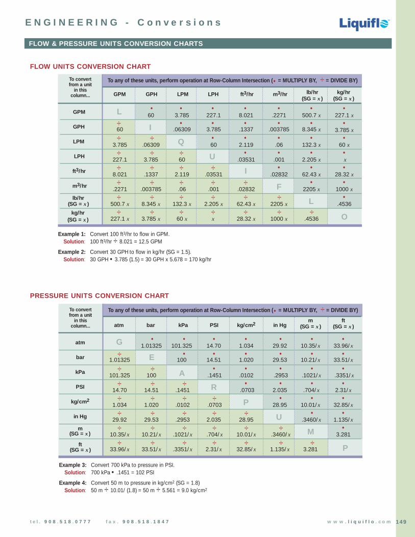
Chemical Processing Pumps
Chemical Processing Pumps
TM
TM
TM
149t e l . 9 0 8 . 5 1 8 . 0 7 7 7 f a x . 9 0 8 . 5 1 8 . 1 8 4 7 w w w . l i q u i f l o . c o m
FLOW & PRESSURE UNITS CONVERSION CHARTS
E N G I N E E R I N G - C o n v e r s i o n s
atm bar kPa PSI kg/cm2 in Hgm ft
(SG = x) (SG = x)
atm 1.01325 101.325 14.70 1.034 29.92 10.35/x 33.96/x
bar 1.01325 100 14.51 1.020 29.53 10.21/x 33.51/x
kPa 101.325 100 .1451 .0102 .2953 .1021/x .3351/x
PSI 14.70 14.51 .1451 .0703 2.035 .704/x 2.31/x
kg/cm21.034 1.020 .0102 .0703 28.95 10.01/x 32.85/x
in Hg 29.92 29.53 .2953 2.035 28.95 .3460/x 1.135/x
m10.35/x 10.21/x .1021/x .704/x 10.01/x .3460/x 3.281
33.96/x 33.51/x .3351/x 2.31/x 32.85/x 1.135/x 3.281
To convertfrom a unit
in thiscolumn...
ft(SG = x)
(SG = x)
To any of these units, perform operation at Row-Column Intersection (• = MULTIPLY BY, ÷ = DIVIDE BY)
• • • • • • •
÷ • • • • • •
÷ ÷ • • • • •
÷ ÷ ÷ • • • •
÷ ÷ ÷ ÷ • • •
÷ ÷ ÷ ÷ ÷ • •
÷ ÷ ÷ ÷ ÷ ÷ •
÷ ÷ ÷ ÷ ÷ ÷ ÷
PRESSURE UNITS CONVERSION CHART
FLOW UNITS CONVERSION CHART
atm bar kPa PSI kg/cm2 in Hgm ft
(SG = x) (SG = x)
GPM 60 3.785 227.1 8.021 .2271 500.7 x 227.1 x
GPH 60 .06309 3.785 .1337 .003785 8.345 x 3.785 x
LPM 3.785 .06309 60 2.119 .06 132.3 x 60 x
LPH 227.1 3.785 60 .03531 .001 2.205 x x
ft3/hr 8.021 .1337 2.119 .03531 .02832 62.43 x 28.32 x
m3/hr .2271 .003785 .06 .001 .02832 2205 x 1000 xlb/hr
500.7 x 8.345 x 132.3 x 2.205 x 62.43 x 2205 x .4536kg/hr
227.1 x 3.785 x 60 x x 28.32 x 1000 x .4536
To convertfrom a unit
in thiscolumn...
(SG = x)
(SG = x)
To any of these units, perform operation at Row-Column Intersection (• = MULTIPLY BY, ÷ = DIVIDE BY)
• • • • • • •
÷ • • • • • •
÷ ÷ • • • • •
÷ ÷ ÷ • • • •
÷ ÷ ÷ ÷ • • •
÷ ÷ ÷ ÷ ÷ • •
÷ ÷ ÷ ÷ ÷ ÷ •
÷ ÷ ÷ ÷ ÷ ÷ ÷
G
E
A
R
P
U
M
P
L
I
Q
U
I
F
L
O
GPM GPH LPM LPH ft3/hr m3/hr lb/hr kg/hr
Example 1: Convert 100 ft3/hr to flow in GPM.Solution: 100 ft3/hr ÷ 8.021 = 12.5 GPM
Example 2: Convert 30 GPH to flow in kg/hr (SG = 1.5).Solution: 30 GPH • 3.785 (1.5) = 30 GPH x 5.678 = 170 kg/hr
(SG = x)(SG = x)
Example 3: Convert 700 kPa to pressure in PSI.Solution: 700 kPa • .1451 = 102 PSI
Example 4: Convert 50 m to pressure in kg/cm2 (SG = 1.8)Solution: 50 m ÷ 10.01/ (1.8) = 50 m ÷ 5.561 = 9.0 kg/cm2

Chemical Processing Pumps
Chemical Processing Pumps
TM
TM
TM
150 t e l . 9 0 8 . 5 1 8 . 0 7 7 7 f a x . 9 0 8 . 5 1 8 . 1 8 4 7 w w w . l i q u i f l o . c o m
GREEK ALPHABET & POWER-OF-TEN PREFIXES
E N G I N E E R I N G - S y m b o l s
NAME SYMBOL VALUE UNIT EXAMPLE
atto a 10-18 as attosecond 10-18 second
femto f 10-15 fg femtogram 10-15 gram
pico p 10-12 pF picofarad 10-12 farad
nano n 10-9 nH nanohenry 10-9 henry
micro µ 10-6 µV microvolt 10-6 volt
milli m 10-3 mA milliampere 10-3 ampere
centi c 10-2 cSt centistoke 10-2 stoke
deci d 10-1 dB decibel 10-1 bel
deca D 101 DL decaliter 10 liters
hecto H 102 Hm hectometer 102 meters
kilo k 103 kG kilogauss 103 gauss
mega M 106 MPa megapascal 106 pascals
giga G 109 GHz gigahertz 109 hertz
tera T 1012 TΩ terohm 1012 ohms
peta P 1015 PJ petajoule 1015 joules
exa E 1018 EW exawatt 1018 watts
POWER-OF-TEN PREFIXES
NAME LOWERCASE UPPERCASE NAME LOWERCASE UPPERCASE
Alpha α Α Nu ν ΝBeta β Β Xi ξ Ξ
Gamma γ Γ Omicron ο Ο
Delta δ ∆ Pi π ΠEpsilon ε Ε Rho ρ Ρ
Zeta ζ Ζ Sigma σ ΣEta η Η Tau τ Τ
Theta θ Θ Upsilon υ Υ
Iota ι Ι Phi φ Φ
Kappa κ Κ Chi χ ΧLambda λ Λ Psi ψ Ψ
Mu µ Μ Omega ω Ω
GREEK ALPHABET

Chemical Processing Pumps
Chemical Processing Pumps
TM
TM
TM
151t e l . 9 0 8 . 5 1 8 . 0 7 7 7 f a x . 9 0 8 . 5 1 8 . 1 8 4 7 w w w . l i q u i f l o . c o m
E N G I N E E R I N G - N o t e sNAME LOWERCASE UPPERCASE NAME LOWERCASE UPPERCASE

E N G I N E E R I N G - N o t e sNAME LOWERCASE UPPERCASE NAME LOWERCASE UPPERCASE
Chemical Processing Pumps
Chemical Processing Pumps
TM
TM
TM
152 t e l . 9 0 8 . 5 1 8 . 0 7 7 7 f a x . 9 0 8 . 5 1 8 . 1 8 4 7 w w w . l i q u i f l o . c o m