T. Norimatsu , Y. Kozaki , N. Miyanaga H. Azechi , H ... · PDF fileT. Norimatsu (ILE) Purpose...
44
ILE, Osaka Critical Issue in KOYO-F Design T. Norimatsu 1) , Y. Kozaki 2) , N. Miyanaga 1) , H. Azechi 1) , H. Furukawa 3) , and K. Tomabechi 4) 1) Institute of Laser Engineering, Osaka University, Suita, Osaka 5650871 Japan. 2) National Institute for Fusion Science, Oroshi, Toki, Gifu, 5095292 Japan 3) Institute for Laser Technology, Nishi-ku, Osaka, 5500004, Japan. 4) Previous Advisor of Central Research Institute of Electric Power Industry Presented at Japan-US workshop on Reactor Design, Feb. 5-7, 2007, Kyoto
Transcript of T. Norimatsu , Y. Kozaki , N. Miyanaga H. Azechi , H ... · PDF fileT. Norimatsu (ILE) Purpose...

ILE, OsakaCritical Issue in KOYO-F Design
T. Norimatsu 1), Y. Kozaki 2), N. Miyanaga 1), H. Azechi 1), H. Furukawa 3),
and K. Tomabechi 4)
1) Institute of Laser Engineering, Osaka University, Suita, Osaka 5650871 Japan.
2) National Institute for Fusion Science, Oroshi, Toki, Gifu, 5095292 Japan3) Institute for Laser Technology, Nishi-ku, Osaka, 5500004, Japan.4) Previous Advisor of Central Research Institute of Electric Power
IndustryPresented at Japan-US workshop on Reactor Design, Feb. 5-7, 2007, Kyoto

ILE, Osaka
Reactor Design Committee was organized to clarify the feasibility of Laser Fusion Plant based
on Fast Ignitionby IFE Forum and ILE, Osaka University
• Chair; A. Tomabechi• Co-chair; Y. Kozaki (IFE, Forum)
T. Norimatsu (ILE, Osaka)
Core plasma Working Group
H. Azechi (ILE),
Y. Nakao (Kyushu Univ.),
H. Sakagami (Hyogo Unv.),
H. Shiraga (ILE),
R. Kodama (ILE),
H., Nagatomo(ILE),
T. Johzaki (ILE)
Laser Working Group
N. Miyanaga (ILE),
Y. Suzuki (Laser Front Technol.),
K. Ueda (Univ. Elector-Com.),
N. Tuchiya (Nishin Co.)
Y. Oowadano (AIST),
T. Jitsuno (ILE),
M. Nakatsuka (ILE),
H. Fujita (ILE),
K. Yoshida (Osaka Inst. Technol.),
J. Kawanaka (ILE),
H. Nakano (Kinki Univ.),
Y. Fujimoto (ILE),
H. Kubomura (HP),
T. Kawashima (HP),
S. Matsuoka(HP),
T. Ikegawa(HP),
K. Tusbakimoto (ILE),
J. Nishimae (Mitsubishi Elec.),
H. Furukawa (ILT)
Target Working Group
T. Norimatsu (ILE),
M. Nishikawa (Kyushu Univ.),
T. Konishi (Kyoto Univ.),
T. Endo (Hiroshima Univ.),
H. Yoshida (Gifu Univ.),
M. Nakai (ILE)
Plant system Working Group
Y. Kozaki (ILE),
Y. Soman (Mitsubishi Heavy Ind.),
K. Okano (CRIEPI),
Y. Furukawa (ILT),
Y. Sakawa (Nagoya Univ.),
A. Sagara (NIFS),
T. Norimatsu (ILE)
Purpose1) to make a reliable scenario for the fast
ignition power plant basing on the latest knowledge of elemental technologies,
2) to identify the research goal of the elements
3) to make the critical path clear.
ILE, Osaka
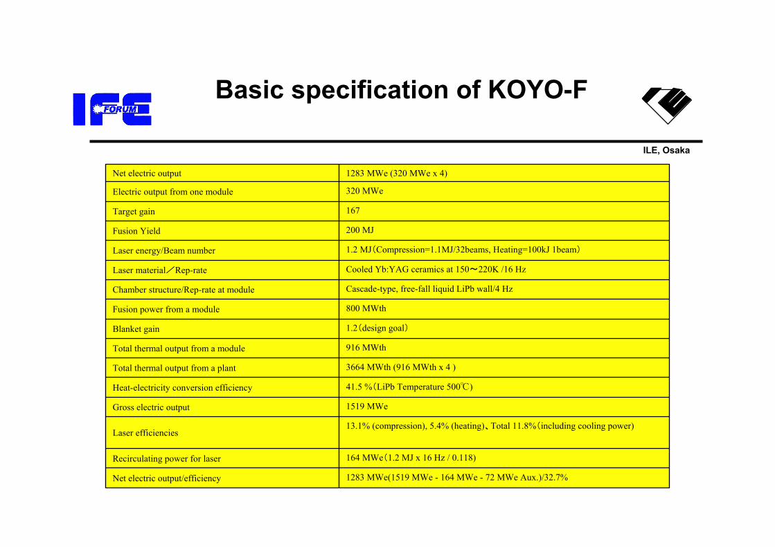
Basic specification of KOYO-F
1283 MWe(1519 MWe - 164 MWe - 72 MWe Aux.)/32.7%Net electric output/efficiency
164 MWe(1.2 MJ x 16 Hz / 0.118)Recirculating power for laser
13.1% (compression), 5.4% (heating)、Total 11.8%(including cooling power)Laser efficiencies
1519 MWeGross electric output
41.5 %(LiPb Temperature 500℃)Heat-electricity conversion efficiency
3664 MWth (916 MWth x 4 )Total thermal output from a plant
916 MWthTotal thermal output from a module
1.2(design goal)Blanket gain
800 MWthFusion power from a module
Cascade-type, free-fall liquid LiPb wall/4 HzChamber structure/Rep-rate at module
Cooled Yb:YAG ceramics at 150~220K /16 Hz Laser material/Rep-rate
1.2 MJ(Compression=1.1MJ/32beams, Heating=100kJ 1beam)Laser energy/Beam number
200 MJFusion Yield
167Target gain
320 MWeElectric output from one module
1283 MWe (320 MWe x 4)Net electric output
ILE, Osaka
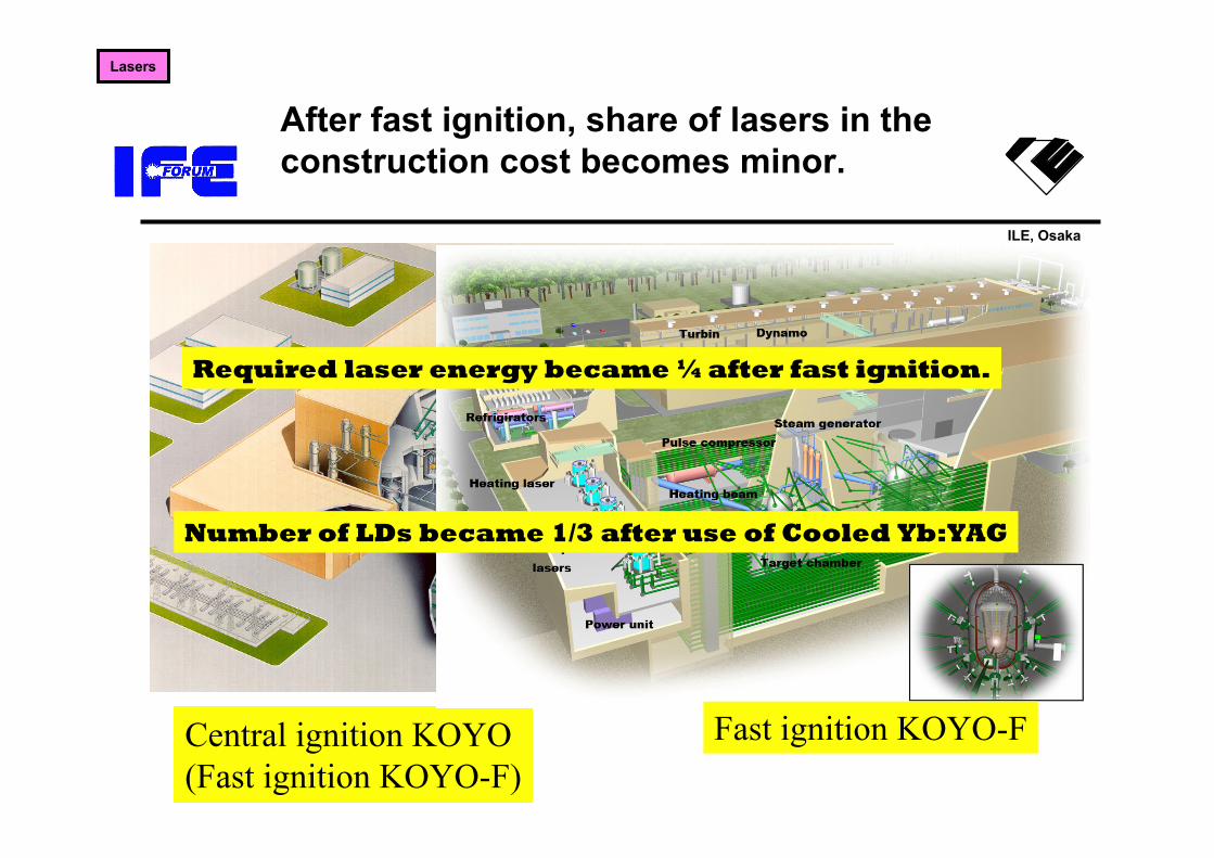
After fast ignition, share of lasers in the construction cost becomes minor.
Central ignition KOYO(Fast ignition KOYO-F)
Fast ignition KOYO-F
Lasers
Required laser energy became ¼ after fast ignition.
Number of LDs became 1/3 after use of Cooled Yb:YAG

ILE, Osaka
Conclusion of design committee
– 1) We have examined the design windows and the issues of the fast ignition laser fusion power plants, ~1200 MWe modular power plants driven at ~16 Hz
– 2) We concluded that such power plant can be constructed with improving current technologies and existing materials.
Our discussion based on limited data available now and left some important issue to be discussed.
ILE, Osaka
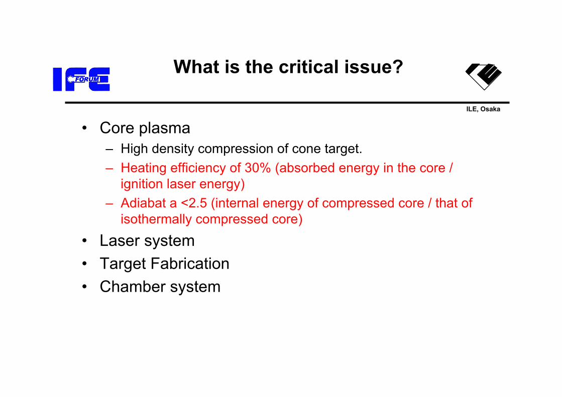
What is the critical issue?
• Core plasma– High density compression of cone target.– Heating efficiency of 30% (absorbed energy in the core /
ignition laser energy)– Adiabat a <2.5 (internal energy of compressed core / that of
isothermally compressed core)
• Laser system• Target Fabrication• Chamber system

ILE, OsakaSimulation of non-spherical implosion for FIREX-I experiment (by PINOCO-2D)
The detail physics of the Fast Ignition are investigated with computational simulations
Generation of high energy electron (by FISCOF2D)
Heating of core plasma by the high energy electrons is simulated (by FIBMET)
Core plasma
0 5 10 15 20102
103
104
105
106
107
1.8 MeV
0.35 MeV
5.0 MeV
Elec
tron
num
ber [
arb.
uni
t]
Electron energy [MeV]
cone
0 1 2 3 4 5 6 70.25
0.30
0.35
0.40
0.45
0.50
T core
[ke
V]Time [ps]
Te Ti
ne,rear= 2nc
ne,rear= 100nc
ne,rear= 10nc
Beam condition
0 1 2 3 4 5 6 70.25
0.30
0.35
0.40
0.45
0.50
T core
[ke
V]Time [ps]
Te Ti
ne,rear= 2nc
ne,rear= 100nc
ne,rear= 10nc
Beam condition
w/ initial perturbation
w/O initial perturbation
Electron spectrum generated by the laser plasma interaction in the cone geometry
Magnetic field in the cone geometry. The hot electrons are transported along cone surface guided by static magnetic and electric field.
CH-DT shell target with gold cone is imploded by GXII laser. Even though, initial perturbation exists on the target surface, high density core plasma is formed.
In this simulation, initial condition of core plasma is determined by the implosion simulation, PINOCO-2D. Boundary condition of Input hot electron is determined by FISCOF2D.Temporal profiles of bulk-electron and ion temperatures averaged over the dense core region (r > 10g/cc) obtained for the three different REB conditions (ne,rear = 2, 10 and 100 nc)
ILE, Osaka
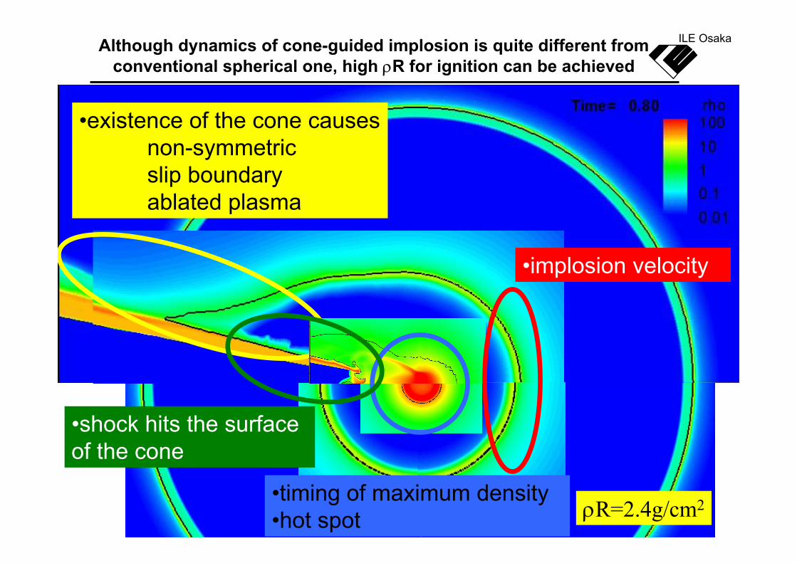
ILE OsakaAlthough dynamics of cone-guided implosion is quite different from conventional spherical one, high ρR for ignition can be achieved
•existence of the cone causesnon-symmetric slip boundaryablated plasma
•implosion velocity
•timing of maximum density•hot spot
•shock hits the surface of the cone
ρR=2.4g/cm2
ILE, Osaka
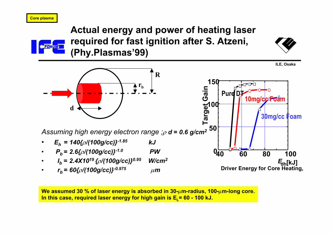
Actual energy and power of heating laser required for fast ignition after S. Atzeni, (Phy.Plasmas’99)
Assuming high energy electron range ;ρ d = 0.6 g/cm2
• Eh = 140{ρ/(100g/cc)}-1.85 kJ• Pb = 2.6{ρ/(100g/cc)}-1.0 PW• Ib = 2.4X10¹⁹ {ρ/(100g/cc)}0.95 W/cm2
• rb = 60{ρ/(100g/cc)}-0.975 µm
d
Rrb
We assumed 30 % of laser energy is absorbed in 30-µm-radius, 100-µm-long core.In this case, required laser energy for high gain is EL= 60 - 100 kJ.
Core plasma
40 60 80 1000
50
100
150
Targ
et G
ain
Driver Energy for Core Heating, Edh[kJ]
Pure DT10mg/cc Foam
30mg/cc Foam
ILE, Osaka
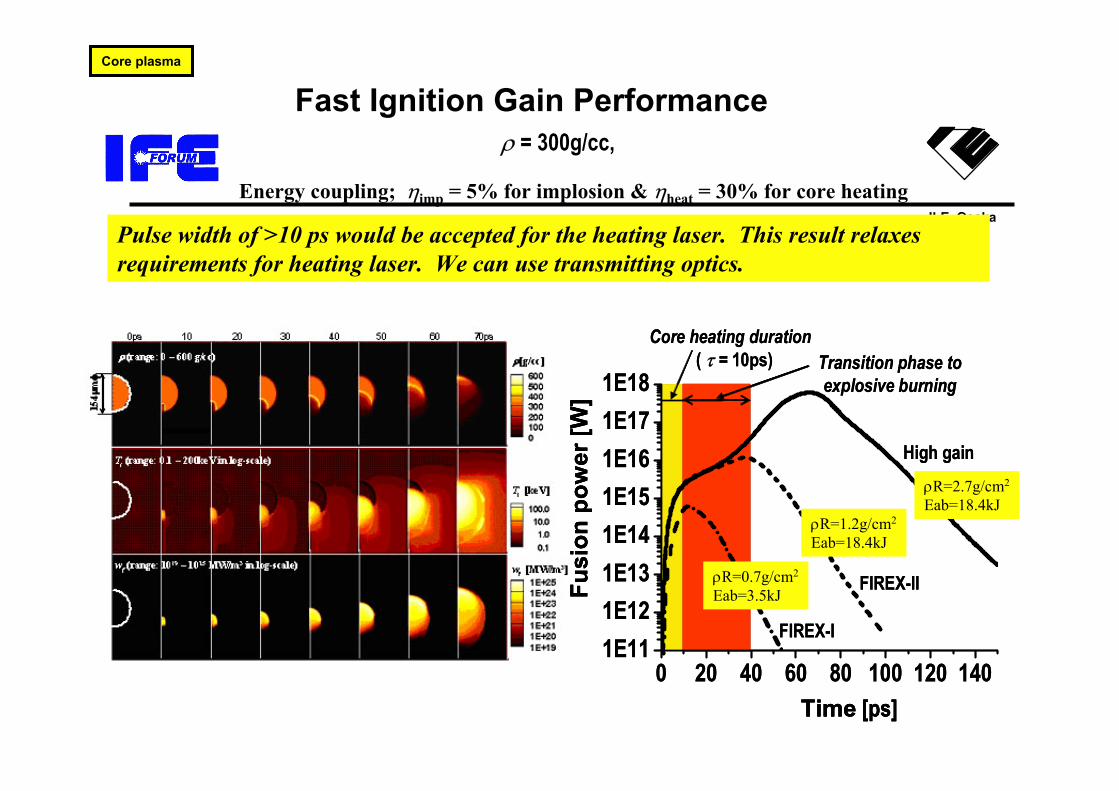
Fast Ignition Gain Performance ρ = 300g/cc,
Energy coupling; ηimp = 5% for implosion & ηheat = 30% for core heating
Pulse width of >10 ps would be accepted for the heating laser. This result relaxes requirements for heating laser. We can use transmitting optics.
Core plasma
0 20 40 60 80 100 120 1401E111E121E131E141E151E161E171E18
Fu
sion
pow
er [W
]
Time [ps]
Core heating duration ( τ = 10ps)
High gain
Transition phase to explosive burning
FIREX-I
FIREX-II
0 20 40 60 80 100 120 1401E111E121E131E141E151E161E171E18
Fu
sion
pow
er [W
]
Time [ps]
Fusi
on p
ower
[W]
Time [ps]
Core heating duration ( τ = 10ps)
High gain
Transition phase to explosive burning
FIREX-I
FIREX-IIρR=0.7g/cm2
Eab=3.5kJ
ρR=1.2g/cm2
Eab=18.4kJ
ρR=2.7g/cm2
Eab=18.4kJ
ILE, Osaka
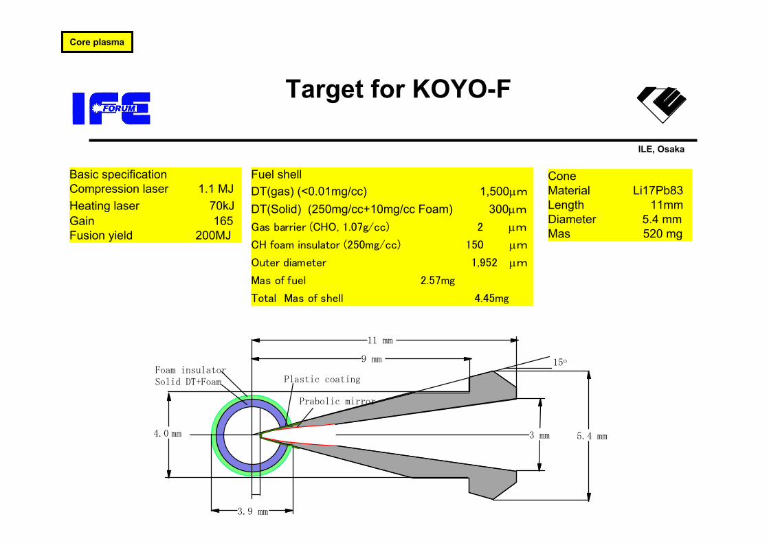
Target for KOYO-F
Fuel shell DT(gas) (<0.01mg/cc) 1,500µm
DT(Solid) (250mg/cc+10mg/cc Foam) 300µm
Gas barrier (CHO, 1.07g/cc) 2 µm
CH foam insulator (250mg/cc) 150 µm
Outer diameter 1,952 µm
Mas of fuel 2.57mg
Total Mas of shell 4.45mg
Basic specification Compression laser 1.1 MJ Heating laser 70kJ Gain 165 Fusion yield 200MJ
Cone Material Li17Pb83 Length 11mm Diameter 5.4 mm Mas 520 mg
3.9 mm
15o9 mm
11 mm
5.4 mm3 mm4.0 mm
Plastic coating
Prabolic mirror
Foam insulator Solid DT+Foam
Core plasma

ILE, Osaka
Issues toward high gain
• Can we achieve low adiabatα ?– Current experiments α >2.4
Pulse control is necessary. Self-Ignition
High-Gain
Driven-Ignition
ELtot [kJ]G
ain,
Q
α = 3
10 100 10000.1
1
10
100 α = 2
FIREX-1
FIREX-2
Wet wall reactor
Dry wall reactor
Self-Ignition
High-Gain
Driven-Ignition
ELtot [kJ]G
ain,
Q
α = 3
10 100 10000.1
1
10
100 α = 2
FIREX-1
FIREX-2
FIREX-1
FIREX-2
Wet wall reactor
Dry wall reactor
104
106
108
0.1 1
Neu
tron
Yie
ld
Heating Laser Power (PW)
η = 15%
Heating efficiency η = 30%
Ignition Equivalent Laser Intensity
•Can we deposit 20-30% heating laser energy in a 60 µm diameter x 100 µm area?
•Current theory 15-20 %
?
These issues seems important but not critical.

ILE, Osaka
What is the critical issue?
• Core plasma• Laser system
– Construction of laser itself seems possible with existing technology.
– Beam steering of ignition beam may be critical.
• Target Fabrication• Chamber system
ILE, Osaka
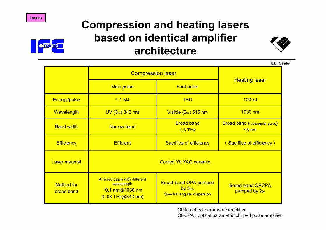
OPA: optical parametric amplifierOPCPA : optical parametric chirped pulse amplifier
Compression and heating lasers based on identical amplifier
architecture
100 kJTBD1.1 MJEnergy/pulse
Cooled Yb:YAG ceramicLaser material
1030 nmVisible (2ω) 515 nmUV (3ω) 343 nmWavelength
( Sacrifice of efficiency )Sacrifice of efficiencyEfficientEfficiency
Foot pulseMain pulse
Broad-band OPA pumped by 3ω,
Spectral angular dispersion
Broad band1.6 THz
Broad-band OPCPA pumped by 2ω
Arrayed beam with different wavelength
~0.1 nm@1030 nm(0.08 THz@343 nm)
Method forbroad band
Broad band (rectangular pulse)~3 nm
Narrow bandBand width
Heating laserCompression laser
Lasers
ILE, Osaka
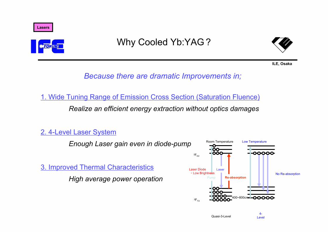
Why Cooled Yb:YAG ?
1. Wide Tuning Range of Emission Cross Section (Saturation Fluence)
Realize an efficient energy extraction without optics damages
2. 4-Level Laser System
Enough Laser gain even in diode-pump
3. Improved Thermal Characteristics
High average power operation
Because there are dramatic Improvements in;
Room Temperature
Pump
Laser
Re-absorption
Laser Diode・Low Brightness
400~800cm-1
Quasi-3-Level
2F7/2
2F5/2
Low Temperature
No Re-absorption
4-Level
Lasers
ILE, Osaka
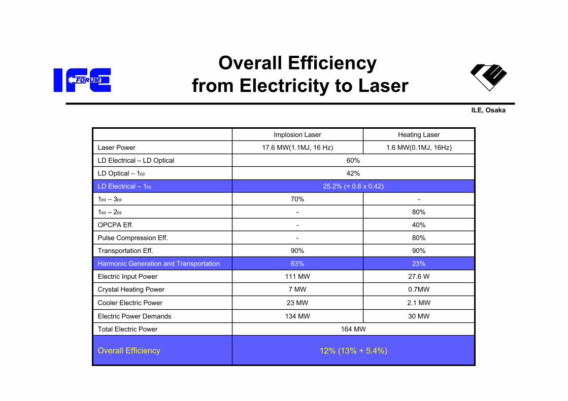
Overall Efficiencyfrom Electricity to Laser
164 MWTotal Electric Power
30 MW134 MWElectric Power Demands
2.1 MW23 MWCooler Electric Power
0.7MW7 MWCrystal Heating Power
27.6 W111 MWElectric Input Power
23%
12% (13% + 5.4%)Overall Efficiency
63%Harmonic Generation and Transportation
90%90%Transportation Eff.
80%-Pulse Compression Eff.
40%-OPCPA Eff.
80%-1ω – 2ω
-70%1ω – 3ω
25.2% (= 0.6 x 0.42)LD Electrical – 1ω
42%LD Optical – 1ω
60%LD Electrical – LD Optical
1.6 MW(0.1MJ, 16Hz)17.6 MW(1.1MJ, 16 Hz)Laser Power
Heating LaserImplosion Laser
ILE, Osaka
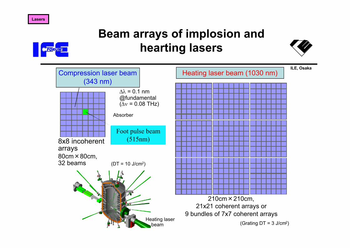
Beam arrays of implosion and hearting lasers
Compression laser beam(343 nm)
Absorber
8x8 incoherentarrays
Heating laser beam (1030 nm)
Foot pulse beam(515 nm)
Heating laser beam
80cm×80cm,32 beams
∆λ = 0.1 nm@fundamental(∆ν = 0.08 THz)
(Grating DT = 3 J/cm2)
(DT = 10 J/cm2)
210cm×210cm,21x21 coherent arrays or
9 bundles of 7x7 coherent arrays
Lasers
Foot pulse beam(515nm)
ILE, Osaka
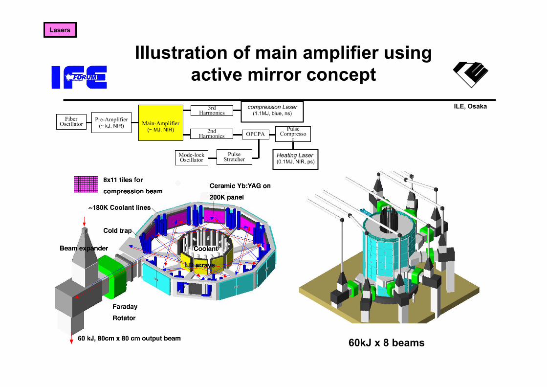
Illustration of main amplifier using active mirror concept
Lasers
60kJ x 8 beams
FiberOscillator
Pre-Amplifier(~ kJ, NIR) Main-Amplifier
(~ MJ, NIR)
3rd Harmonics
2nd Harmonics
PulseCompresso
r
compression Laser(1.1MJ, blue, ns)
Heating Laser(0.1MJ, NIR, ps)
OPCPA
PulseStretcher
Mode-lockOscillator
ILE, Osaka
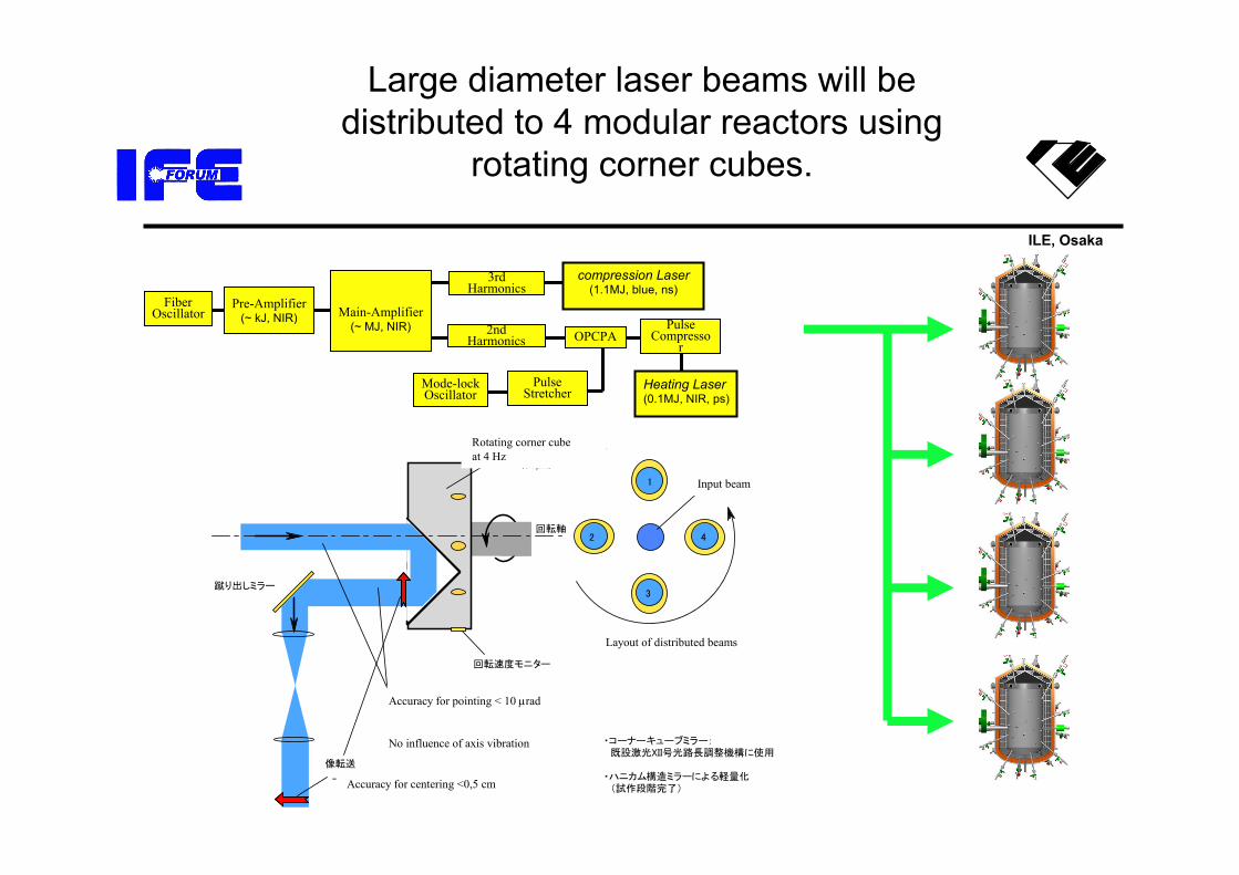
・コーナーキューブミラー: 既設激光XII号光路長調整機構に使用 ・ハニカム構造ミラーによる軽量化 (試作段階完了)
1
3
分配ビーム配置
回転コーナーキューブミラー
回転軸
蹴り出しミラー
入射ビーム
平行度 < 10 µrad(工作精度) → ポインティング精度* < 10 µrad (歳差運動の影響無し)
像転送
→ センタリング精度* < 1cm(回転周期変動= 0.1%)
* : 最終集光系上で
回転速度モニター
42
(3 rpm)
Large diameter laser beams will be distributed to 4 modular reactors using
rotating corner cubes.
FiberOscillator
Pre-Amplifier(~ kJ, NIR) Main-Amplifier
(~ MJ, NIR)
3rd Harmonics
2nd Harmonics
PulseCompresso
r
compression Laser(1.1MJ, blue, ns)
Heating Laser(0.1MJ, NIR, ps)
OPCPA
PulseStretcher
Mode-lockOscillator
Rotating corner cubeat 4 Hz
Accuracy for pointing < 10 µrad
No influence of axis vibration
Accuracy for centering <0,5 cm
Layout of distributed beams
Input beam
ILE, Osaka
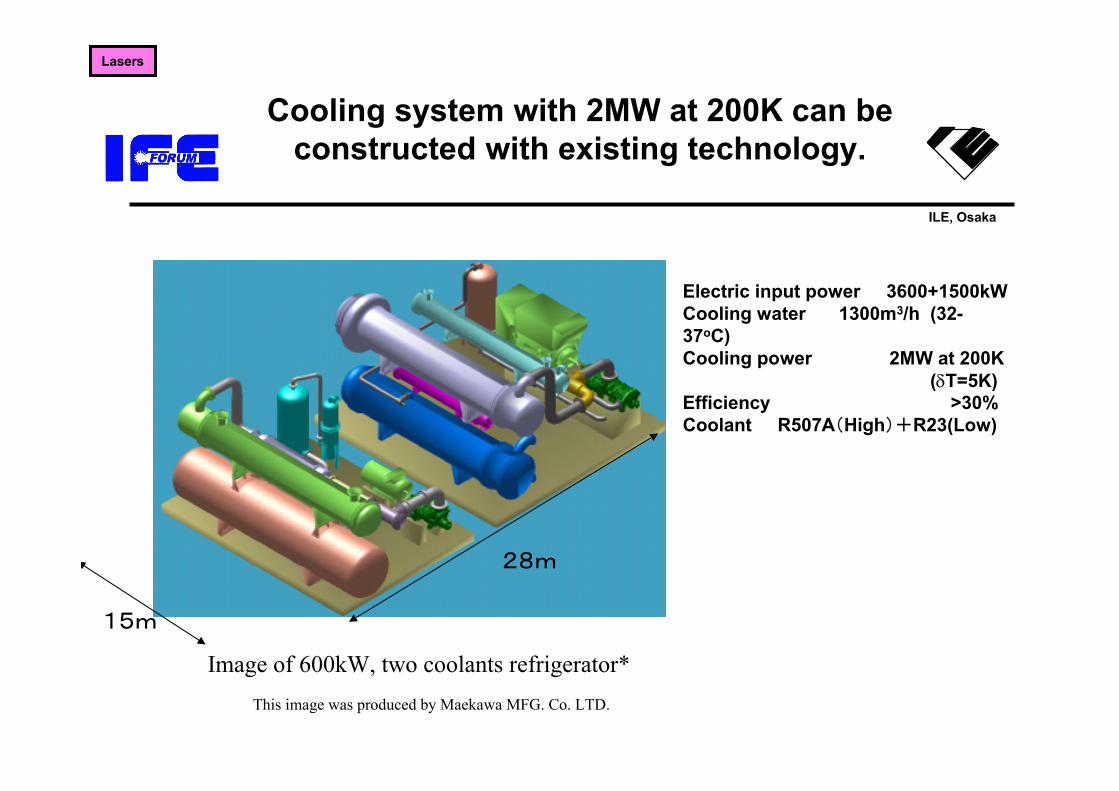
Cooling system with 2MW at 200K can be constructed with existing technology.
15m
28m
Image of 600kW, two coolants refrigerator*This image was produced by Maekawa MFG. Co. LTD.
Electric input power 3600+1500kWCooling water 1300m3/h (32-37oC)Cooling power 2MW at 200K
(δT=5K)Efficiency >30%Coolant R507A(High)+R23(Low)
Lasers
ILE, Osaka
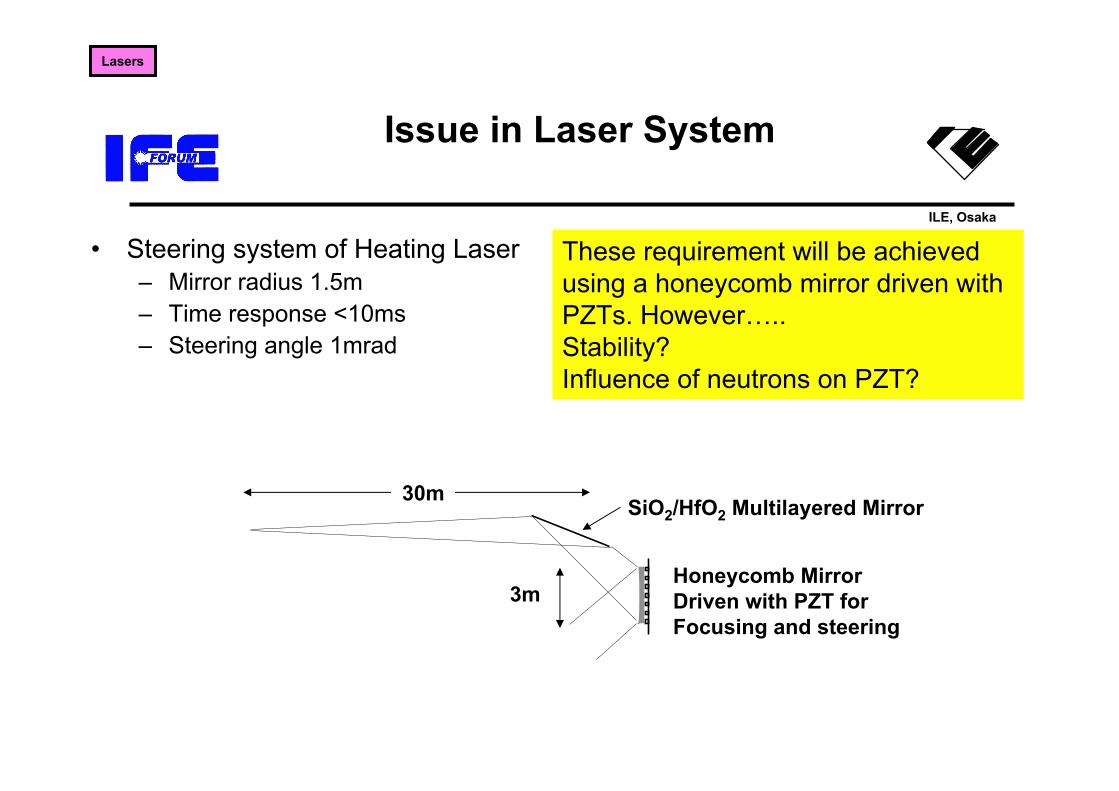
Issue in Laser System
• Steering system of Heating Laser– Mirror radius 1.5m– Time response <10ms– Steering angle 1mrad
SiO2/HfO2 Multilayered Mirror
Honeycomb MirrorDriven with PZT for Focusing and steering
30m
3m
These requirement will be achieved using a honeycomb mirror driven with PZTs. However…..Stability? Influence of neutrons on PZT?
Lasers

ILE, Osaka
What is the critical issue?
• Core plasma
• Laser system• Target Fabrication
– Low density foam, cone with LiPb– Accuracy for the initial ρR/Ilaser
• Chamber system
ILE, Osaka
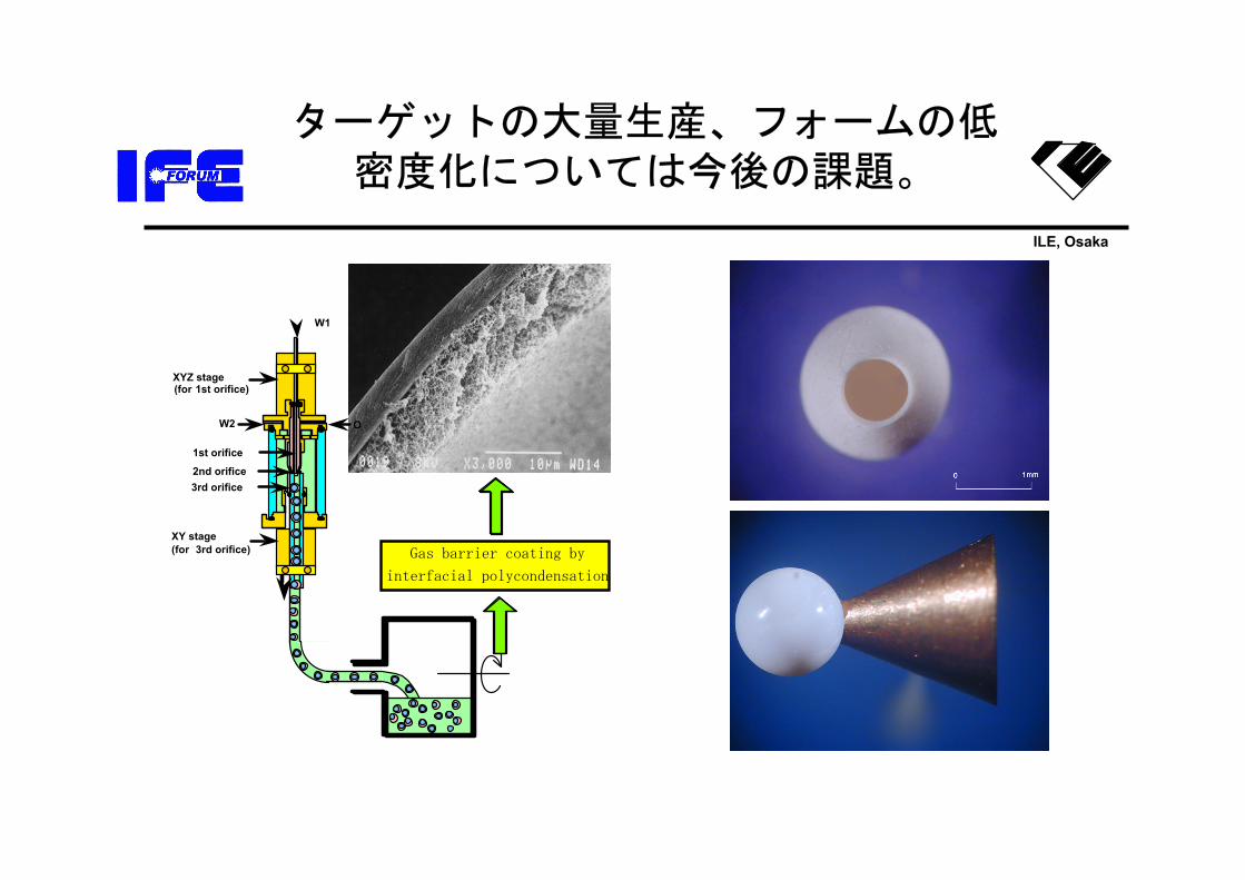
ターゲットの大量生産、フォームの低密度化については今後の課題。
OW2
1st orifice
2nd orifice
W1
XYZ stage(for 1st orifice)
3rd orifice
XY stage(for 3rd orifice) Gas barrier coating by
interfacial polycondensation
ILE, Osaka
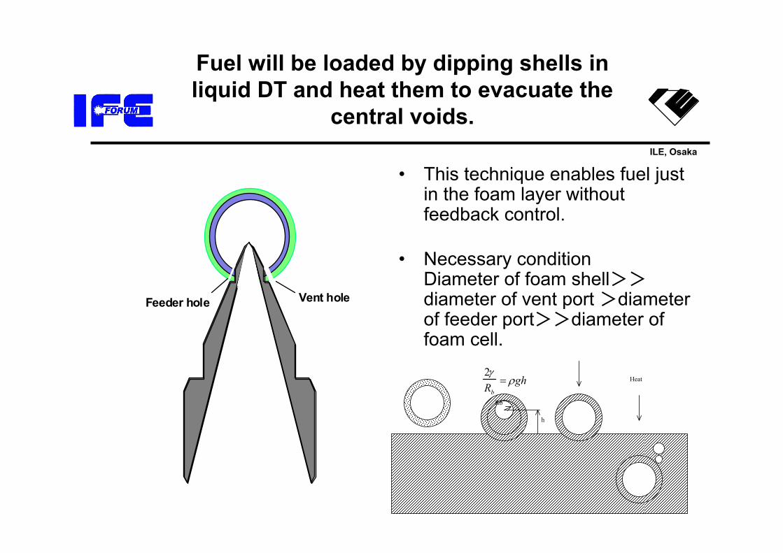
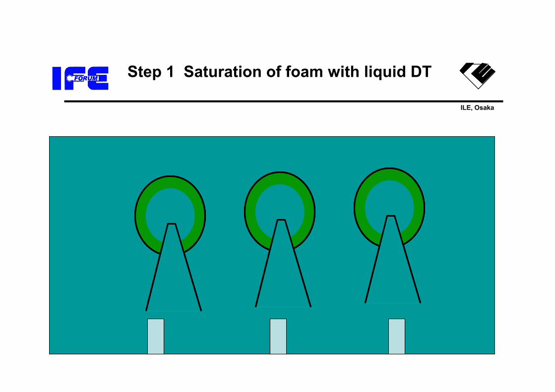
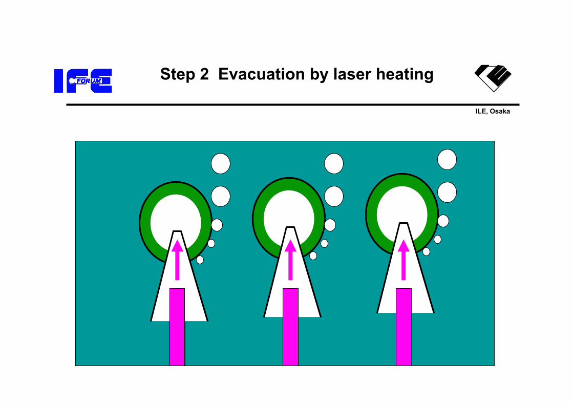
Fuel will be loaded by dipping shells in liquid DT and heat them to evacuate the
central voids.
• This technique enables fuel just in the foam layer without feedback control.
• Necessary conditionDiameter of foam shell>>diameter of vent port >diameter of feeder port>>diameter of foam cell.
Vent holeFeeder hole
Heat
h
Rb
2γRb
= ρgh
ILE, Osaka
Step 1 Saturation of foam with liquid DT
ILE, Osaka
Step 2 Evacuation by laser heating
ILE, Osaka
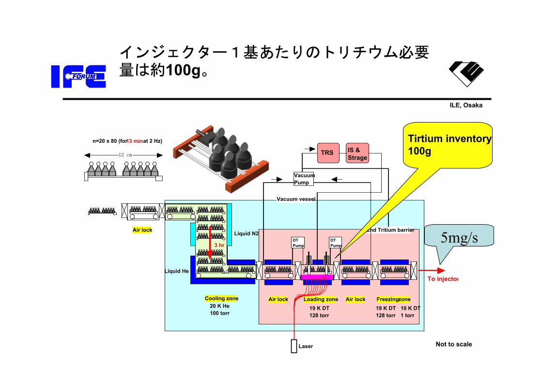
インジェクター1基あたりのトリチウム必要量は約100g。
n=20 x 80 (for 13 min at 2 Hz)
12 cm
Air lock
Air lockAir lockCooling zone Freezing zoneLoading zone
Liquid N2
Liquid He
20 K He 100 torr
19 K DT 128 torr
19 K DT 128 torr
10 K DT 1 torr
DT Pump
DT Pump
2nd Tritium barrier
Vacuum vessel
3 hr
Vacuum Pump
TRS IS & Strage
To injector
Laser Not to scale
Tirtium inventory100g
5mg/s

ILE, Osaka
Hybrid injector for KOYO-F
Injection velocity 300+/-2 m/sRep rate 2 HzPointing +/- 1 mmOperation power including freezer
500 kW
ILE, Osaka
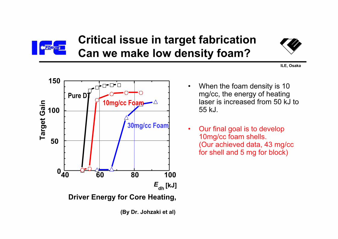
Critical issue in target fabricationCan we make low density foam?
• When the foam density is 10 mg/cc, the energy of heating laser is increased from 50 kJ to 55 kJ.
• Our final goal is to develop 10mg/cc foam shells.(Our achieved data, 43 mg/cc for shell and 5 mg for block)
40 60 80 1000
50
100
150
Targ
et G
ain
Driver Energy for Core Heating,
Edh [kJ]
Pure DT10mg/cc Foam
30mg/cc Foam
(By Dr. Johzaki et al)
ILE, Osaka
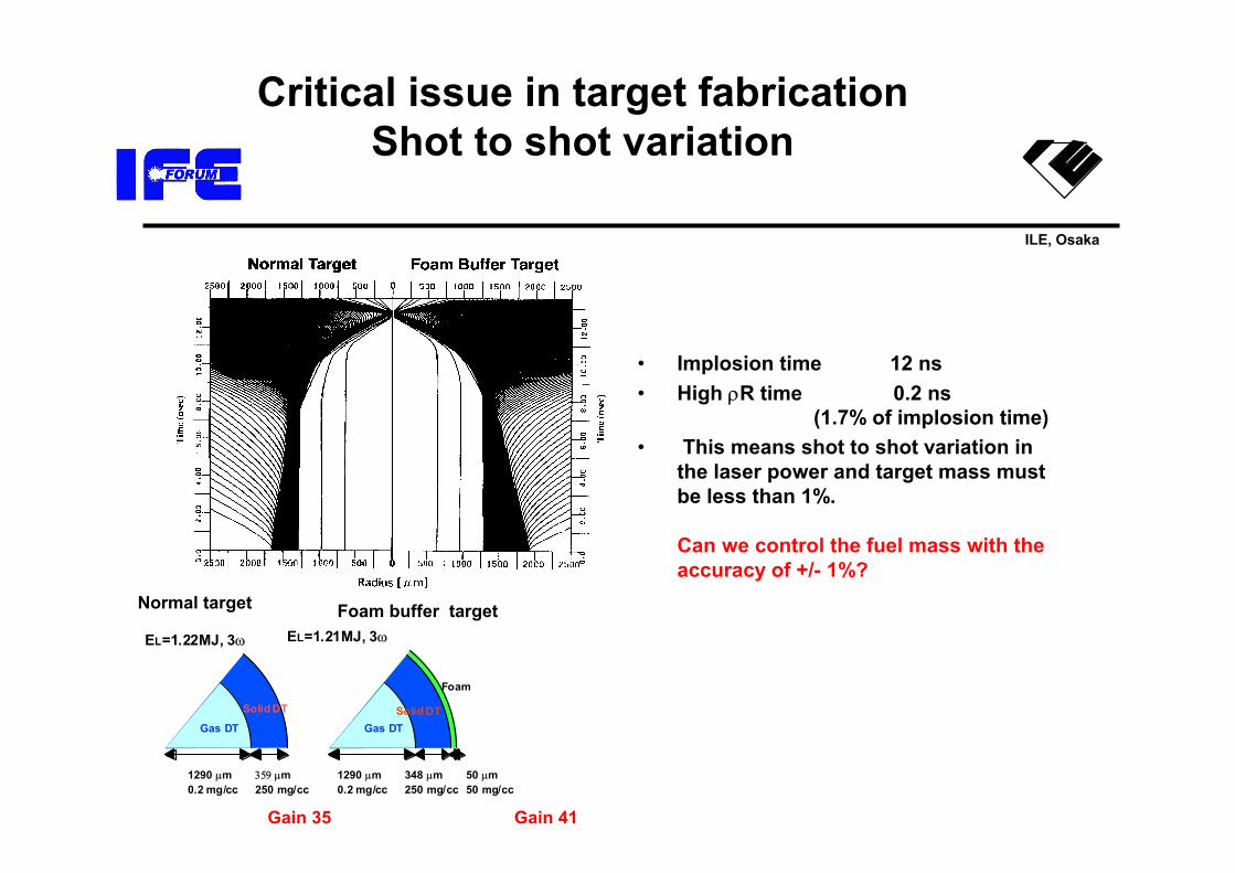
Critical issue in target fabricationShot to shot variation
• Implosion time 12 ns• High ρR time 0.2 ns
(1.7% of implosion time)• This means shot to shot variation in
the laser power and target mass must be less than 1%.
Can we control the fuel mass with the accuracy of +/- 1%?
Foam buffer targetNormal target
Gain 41Gain 35
Solid DT
Gas DT
1290 µm 0.2 mg/cc
359 µm 250 mg/cc
Solid DTGas DT
Foam
1290 µm 0.2 mg/cc
348 µm 250 mg/cc
50 µm 50 mg/cc
EL=1.22MJ, 3ω EL=1.21MJ, 3ω

ILE, Osaka
What is the critical issue?
• Core plasma, • In the laser system
• Target Fabrication• Chamber system
– Protection of beam port– Chamber clearance– Tritium confinement
ILE, Osaka
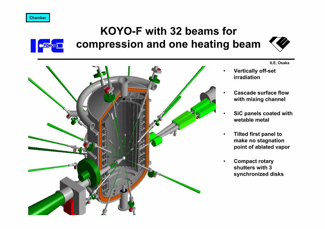
KOYO-F with 32 beams for compression and one heating beam
• Vertically off-set irradiation
• Cascade surface flow with mixing channel
• SiC panels coated with wetable metal
• Tilted first panel to make no stagnation point of ablated vapor
• Compact rotary shutters with 3 synchronized disks
Chamber
ILE, Osaka
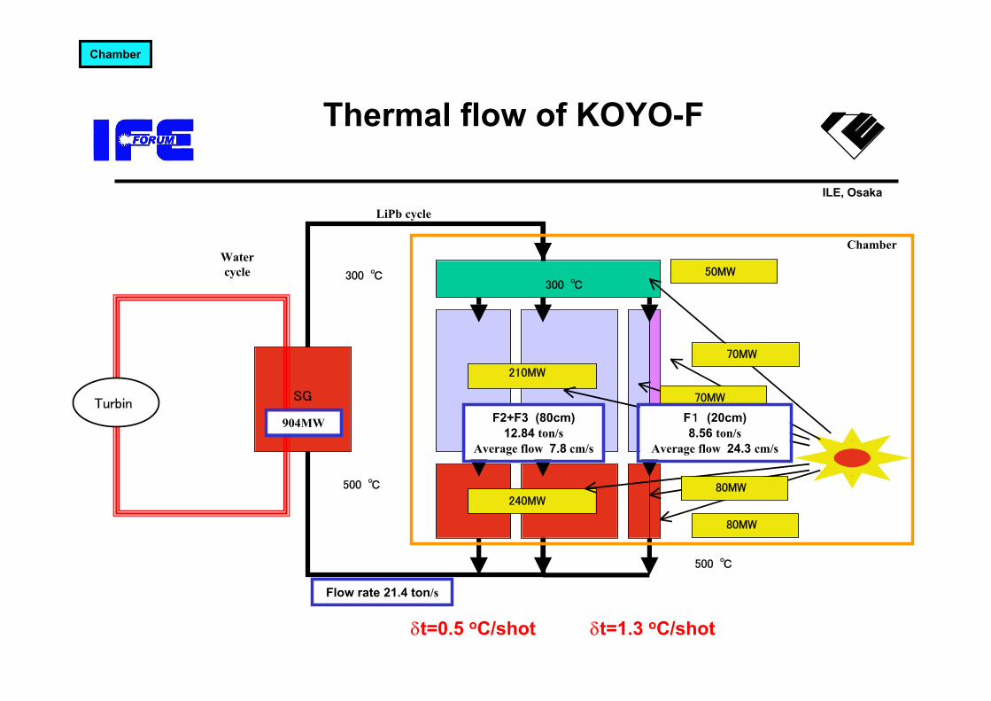
Thermal flow of KOYO-F
SGTurbin
500 ℃
300 ℃300 ℃
50MW
210MW
70MW
70MW
240MW
80MW
80MW
500 ℃
F2+F3 (80cm)12.84 ton/s
Average flow 7.8 cm/s
F1 (20cm)8.56 ton/s
Average flow 24.3 cm/s
Flow rate 21.4 ton/s
904MW
Watercycle
Chamber
LiPb cycle
Chamber
δt=0.5 oC/shot δt=1.3 oC/shot
ILE, Osaka
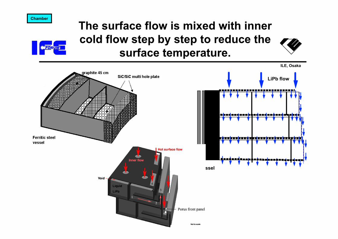
The surface flow is mixed with inner cold flow step by step to reduce the
surface temperature.
Steel vessel
LiPb flow
Chamber

ILE, Osaka
To prevent stagnation of ablated LiPb, front panels were tilted by 30 degree.
Tilted front panels
Cone type ceiling t=0 ms
t=10ms
t=20ms
Chamber
Position of mass center of ablated vapor
ILE, Osaka
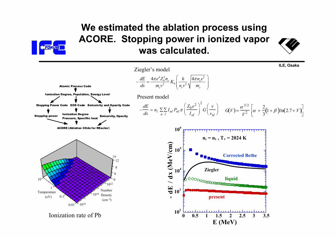
We estimated the ablation process using ACORE. Stopping power in ionized vapor
was calculated.
Atomic Process Code
Ionization Degree, Population, Energy Level
Stopping Power Code EOS Code Emissivity and Opacity Code
Stopping power Ionization DegreePressure, Specifiic heat
Emissivity, Opacity
ACORE (Ablation COde for REactor)
0
4
8
12
Number Density
(cm -3)1014
1018
1022
Temperature (eV)
10
1
0.1
0.01
Z*
Ionization rate of Pb
Ziegler’s model
−dEdx
= ni Inll∑
n∑ Pnl π
Z0e2
Inl
⎛
⎝ ⎜ ⎞
⎠ ⎟
2
Gvvnl
⎛ ⎝ ⎜
⎞ ⎠ ⎟
102
103
104
105
106
0 0.5 1 1.5 2 2.5 3 3.5
ni = nl , Te = 2024 K
liquid
Ref.
present- dE
/ d
x (M
eV/c
m)
E (MeV)
Present model
G V( ) =α 3/2
V 2 α +23
1 + β( )ln 2.7 + V( )⎡ ⎣ ⎢
⎤ ⎦ ⎥
4 2 20
02 2
4 4e e
e e e
e Z n n edE hKdx m v n v m
π π⎛ ⎞− = ⎜ ⎟⎜ ⎟
⎝ ⎠
Ziegler
Corrected Bethe

ILE, Osaka
Density, Temperature and velocity profile of ablated material.
1020
1021
1022
1023
-200
0
200
400
600
800
1000
-0.2 0 0.2 0.4 0.6 0.8 1 1.2
Time = 1932 ns
Number Density
Velocity
Num
ber
Den
sity
(cm
-3)
Velocity (m
/s)
x (mm)1020
1021
1022
1023
-0.2 0 0.2 0.4 0.6 0.8 1 1.2
R = 3 m
595.5 ns
1932 ns
Num
ber
Den
sity
(cm
-3)
x (mm)500
1000
1500
2000
2500
3000
3500
4000
4500
-0.2 0 0.2 0.4 0.6 0.8 1 1.2
R = 3 m
595.5 ns
1932 nsT
empe
ratu
re (K
)
x (mm)
102
103
104
105
106
107
108
109
0.0 0.5 1.0 1.5 2.0
alfaalfa (debri)deuteriumtritiumprotonherium3
Inte
nsit
y (W
/cm
2 )
Time (µs)
ILE, Osaka
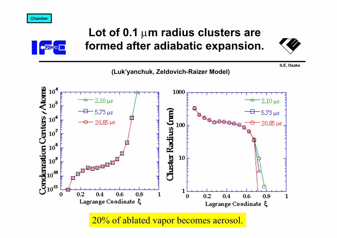
Lot of 0.1 µm radius clusters are formed after adiabatic expansion.
(Luk’yanchuk, Zeldovich-Raizer Model)
Chamber
20% of ablated vapor becomes aerosol.

ILE, Osaka
Beam ports and ceiling will be made with porous metal and followed by condensation of vapor ablated by previous shot.
80%
20%
Diameter 0.1μm
Liquidmembrane
aerosol
Vapor ~1000m/s
Condensation rates of the fast and slow component at the first bounce are about 60% and 100%, respectively.
These rates are sufficient to keep the vapor pressure < 5 Pa and to form a 2 µm-hick, protective layer before the next laser shot.
Chamber
0 2 0 0 0 4 0 0 0 6 0 0 0 8 0 0 0 1 1 04
0
Ti
Pb
蒸気温度(K)
吸着係数
Con
dens
atio
n co
effic
ient
on
col
d su
rfac
e
Vapor temperature (K)
1
Aerosol mainly appears in slow component. Now secondary particles because the surface energy > kinetic energy

ILE, Osaka
Critical issues in chamber 1
• Probability for direct exposure of the same place <1/103 – 1/104
– If we assume maintenance period of 2 years and acceptable erosion of 3-mm-thick, the probability for direct exposure of the same place with α particles must be less than 1/104.
– Improve flow control, material selection, chamber radius
• Protection of beam ports– Our first plan was to keep the surface temperature less than
surrounding area to enhance the condensation. But this would not work because of the small temperature dependence of condensation.
– Porous metal saturated with liquid LiPb– Magnetic field
Dry surfaceLiquid LiPb
ILE, Osaka
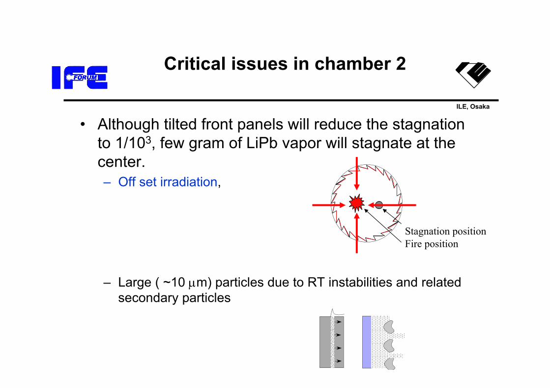
Critical issues in chamber 2
• Although tilted front panels will reduce the stagnation to 1/103, few gram of LiPb vapor will stagnate at the center.– Off set irradiation,
– Large ( ~10 µm) particles due to RT instabilities and related secondary particles
Stagnation positionFire position
ILE, Osaka
n=20 x 80 (for 13 min at 2 Hz)
12 cm
Air lock
Air lockAir lockCooling zone Freezing zoneLoading zone
Liquid N2
Liquid He
20 K He 100 torr
19 K DT 128 torr
19 K DT 128 torr
10 K DT 1 torr
DT Pump
DT Pump
2nd Tritium barrier
Vacuum vessel
3 hr
Vacuum Pump
TRS IS & Strage
To injector
Laser Not to scale
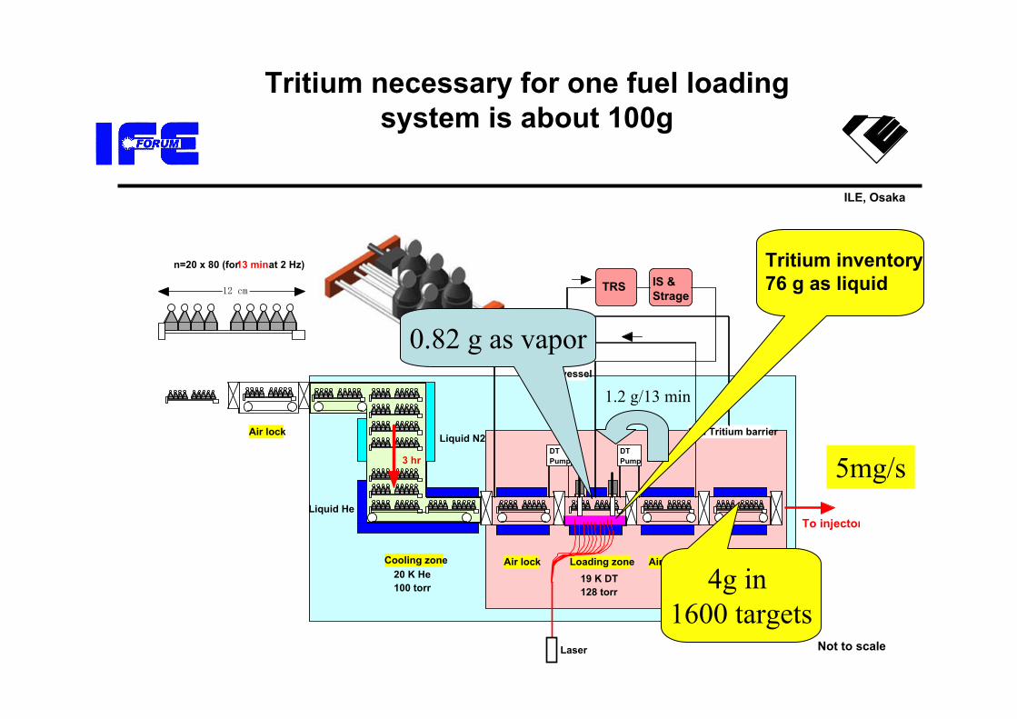
Tritium inventory76 g as liquid
0.82 g as vapor
4g in 1600 targets
1.2 g/13 min
5mg/s
Tritium necessary for one fuel loading system is about 100g
ILE, Osaka
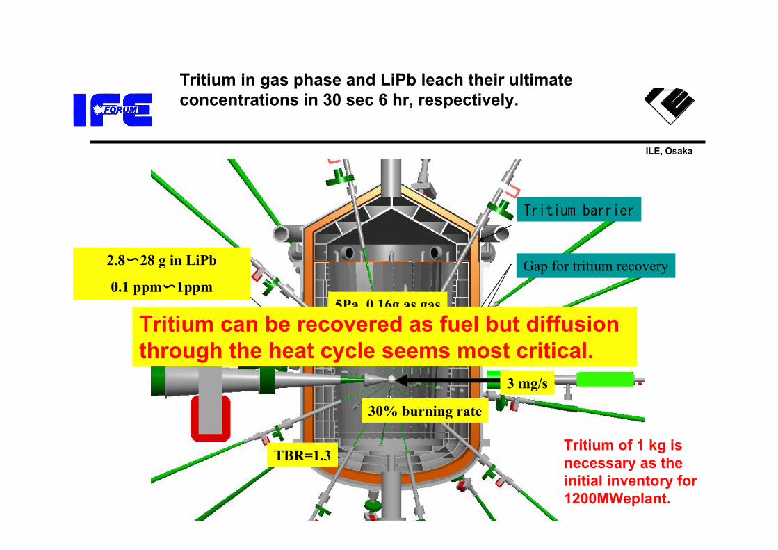
Tritium in gas phase and LiPb leach their ultimate concentrations in 30 sec 6 hr, respectively.
3 mg/s
5Pa, 0.16g as gas
Gap for tritium recovery
Tritium barrier
2.8〜28 g in LiPb
0.1 ppm〜1ppm
TBR=1.3
30% burning rate
Tritium of 1 kg is necessary as the initial inventory for 1200MWeplant.
Tritium can be recovered as fuel but diffusion through the heat cycle seems most critical.
ILE, Osaka
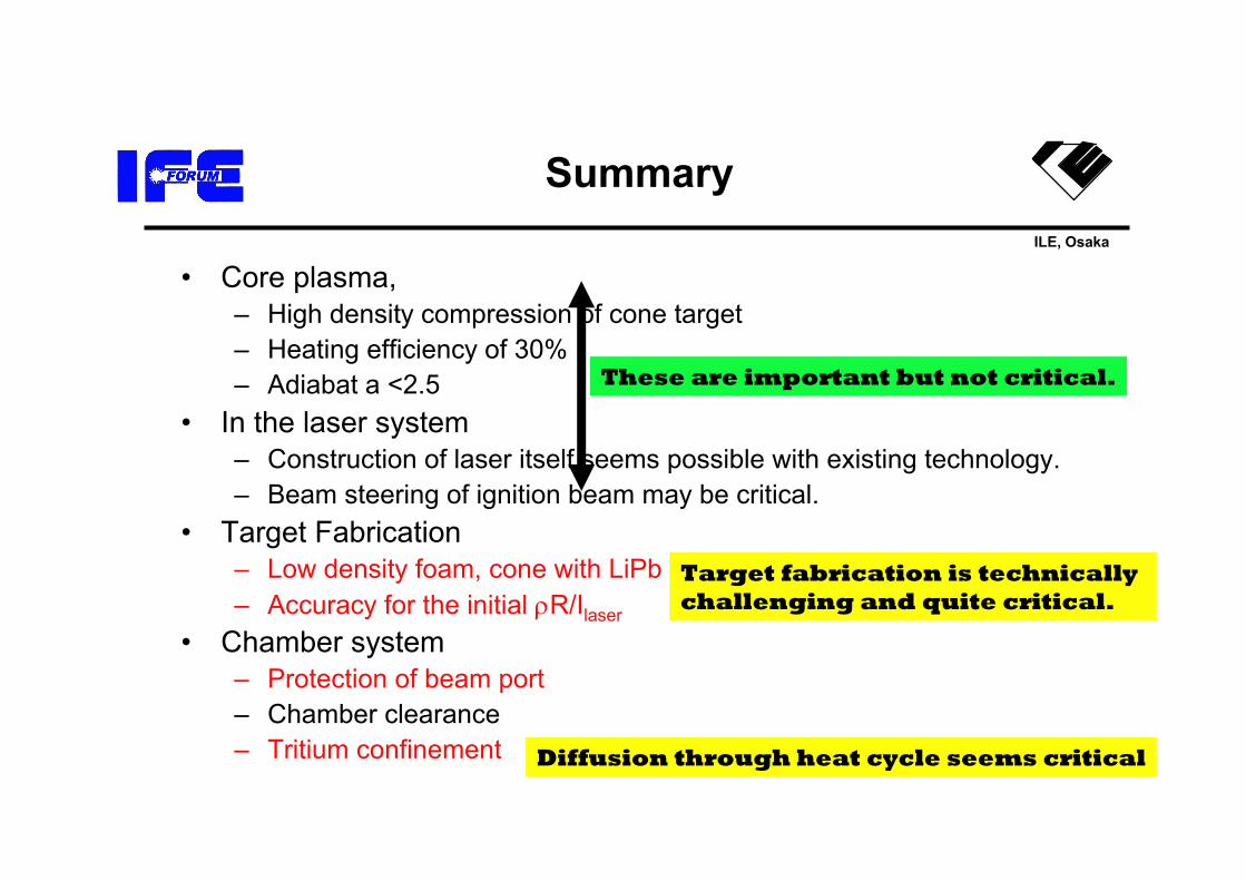
Summary
• Core plasma, – High density compression of cone target– Heating efficiency of 30% – Adiabat a <2.5
• In the laser system– Construction of laser itself seems possible with existing technology.– Beam steering of ignition beam may be critical.
• Target Fabrication– Low density foam, cone with LiPb– Accuracy for the initial ρR/Ilaser
• Chamber system– Protection of beam port– Chamber clearance– Tritium confinement
These are important but not critical.
Target fabrication is technically challenging and quite critical.
Diffusion through heat cycle seems critical