T MOVIDRIVE Drive Inverters · The MOVIDRIVE ® Parameter List contains a list of all the drive...
31
MOVIDRIVE ® Drive Inverters Manual INTERBUS DFI11A Fieldbus Interface Edition 06/98 0919 1410 / 0598
Transcript of T MOVIDRIVE Drive Inverters · The MOVIDRIVE ® Parameter List contains a list of all the drive...

T
MOVIDRIVE®
Drive Inverters
Manual
INTERBUS DFI11A Fieldbus Interface
Edition 06/9809
19 1
410
/ 059
8

2 MOVIDRIVE® DFI11A INTERBUS
Important Notes
Important Notes
• Read this manual carefully before you start installation and commissioning work onMOVIDRIVE® drive inverters with INTERBUS.This manual assumes that the user is familiar with and has at his disposal all relevant docu-mentation on the MOVIDRIVE® system, in particular the Manual and the Installation andOperating Instructions.
• Safety instructions:
Always follow the warnings and safety instructions contained in this Manual.Safety instructions are marked as follows:
Electrical hazard, e.g. during live working
Mechanical hazard, e.g. when working on hoists
Important Instructions for the safe and fault-free operation of the driven machine /system, e.g. pre-settings before commissioning.
• General safety instructions for bus systems:The fieldbus option provides you with a communications system which allows you to matchthe MOVIDRIVE® drive inverter to the specifics of your application to a very high degree. Aswith all bus systems there is, however, the risk of a programming error in the program mayresult in unexpected (though not uncontrolled) system behaviour.
• In this manual, cross-references are marked with a →, e.g.,
(→ MX_SCOPE) means: Please refer to the MX_SCOPE Manual for detailed information orinformation on how to carry out this instruction.(→ Section x.x) means: Further information can be found in Section x.x of this manual.
• Each unit is manufactured and tested to current SEW-EURODRIVE technical standards andspecifications.The manufacturer reserves the right to make changes to the technical data and designswhich are in the interest of technical progress.A requirement for fault-free operation and fulfilment of any rights to claim under guaranteeis that these instructions and notes are followed.

MOVIDRIVE® DFI11A INTERBUS 3
Contents
Contents
1 Introduction ...................................................................................... 4
2 Assembly / Installation Instructions ......................................................... 62.1 Supported Drive Inverter Types .............................................................................62.2 Fitting the Option PCB............................................................................................62.3 Pin Assignment......................................................................................................72.4 Shielding and Laying of the Bus Cables .................................................................82.5 Setting the Process Data Length............................................................................92.6 Display Elements .................................................................................................10
3 Configuration and Commissioning ......................................................... 113.1 Commissioning the Drive Inverter .......................................................................11
3.1.1 Bus Topologies with MOVIDRIVE®.............................................................133.1.2 Direct Connection to Master Modules .......................................................13
3.2 Drive Inverter Module Identity .............................................................................143.3 Configuring the Master Module ...........................................................................14
3.3.1 Configuring for 1 Process Data Word........................................................143.3.2 Configuring for 2 Process Data Words ......................................................153.3.3 Configuring for 3 Process Data Words ......................................................16
4 The PMS Interface ............................................................................ 184.1 PMS Services ......................................................................................................18
4.1.1 Initiate .......................................................................................................184.1.2 Abort .........................................................................................................194.1.3 Read ..........................................................................................................194.1.4 Write..........................................................................................................19
4.2 Object List............................................................................................................194.2.1 Object Description of the Drive Parameters...............................................194.2.2 “Download Parameter Block” Object .........................................................204.2.3 “MOVILINK Cyclic Parameter Channel” Object ..........................................214.2.4 “MOVILINK Acyclic Parameter Channel” Object ........................................23
5 Parameter Adjustment Return Codes ...................................................... 265.1 Internal Communications Error............................................................................26
6 Technical Data of the DFI11A Option ...................................................... 27
Appendix A ..................................................................................... 28
Appendix B ..................................................................................... 29
Index ............................................................................................ 31

4
1 Introduction
1 Introduction
This DFI11A (INTERBUS) Option Manual describes the procedure for installing the DFI11A INTER-BUS option pcb in the drive inverter and for commissioning the MOVIDRIVE® drive inverter whenconnected to an INTERBUS fieldbus system.In addition to describing all the settings on the fieldbus option pcb, this manual further discussesthe various options for connecting the drive inverter to INTERBUS in the form of brief commission-ing examples.In addition to this INTERBUS Option Manual, we recommend that you familiarize yourself with thefollowing more detailed documentation on fieldbuses, which will provide you with the necessaryinformation for simple and efficient connection of the MOVIDRIVE® to the INTERBUS fieldbus sys-tem:• MOVIDRIVE® Fieldbus Device Profile Manual (Pub. No. 0919 1615)• MOVIDRIVE® Manual (Pub. No. 0919 119)The MOVIDRIVE® Fieldbus Device Profile Manual gives a detailed description of the fieldbusparameters and their codes and discusses various control concepts and potential applications inthe form of brief examples.The MOVIDRIVE® Parameter List contains a list of all the drive inverter parameters that can be reador written via the various communications interfaces such as RS-232, RS-485 and via the fieldbusinterface.Thanks to this high-performance, universal fieldbus interface, the MOVIDRIVE® drive inverter withthe DFI11 option can be connected to and controlled from higher-level control systems via theopen and standardized INTERBUS serial sensor/actuator bus system.
MOVIDRIVE® and INTERBUS
The drive inverter device profile for INTERBUS mode, i.e. the way the drive inverter operates andresponds when in INTERBUS mode, is independent of the type of fieldbus, and thus consistent for allfieldbus types. This allows the user to develop his drive applications independent of a particularfieldbus or change to another bus system, e.g. the PROFIBUS-DP/FMS (DFP11A option) fieldbussystem without any problems.MOVIDRIVE® offers digital access to all drive parameters and functions via the INTERBUS interface.The drive inverter is controlled by the high-speed cyclic process data. This process data channelprovides the facility to specify setpoints such as setpoint speeds, ramp generator times for acceler-ation and deceleration etc., and allows various drive functions such as enable, controller inhibit,stop, rapid stop, etc. to be triggered. This channel can also be used to read back actual values fromthe drive inverter, such as actual speed, current, inverter status, fault number or reference mes-sages.Whereas process data are generally exchanged in cycles, the drive parameters can only be readand written acyclically via the READ and WRITE services. This exchange of parameter data enablesapplications where all major drive parameters are stored in the higher-level automation unit to beimplemented, thus avoiding manual adjustment of parameters on the drive inverter itself, whichcan often be very time-consuming.
MOVIDRIVE® DFI11A INTERBUS

Introduction 1
01045AENFig. 1: INTERBUS with MOVIDRIVE®
The INTERBUS option pcb is designed so that all INTERBUS-specific settings, such as the processdata length, can be made on the option pcb by means of a hardware switch. These manual settingsenable the drive inverter to be integrated into the INTERBUS system and switched on in a very shortspace of time. Parameters can be set fully automatically by the higher-level INTERBUS controlsystem (parameter download). This forward-looking version offers the benefits of a shorter com-missioning period for the system as well as simpler documentation of the application program, asall major drive parameter data can now be recorded directly in the control program.The use of a fieldbus system in drive technology requires additional monitoring functions, such asfieldbus timeout or special emergency stop concepts. The monitoring functions of theMOVIDRIVE® can be matched to the specific application for which it is to be used. This featureenables you, for instance, to specify which response the drive inverter should trigger if an errorshould occur in the bus. A rapid stop will be practical for many applications, but it is also possibleto freeze the last setpoints, so that the drive can continue with the last valid setpoints (e.g. con-veyor belt). As the functionality of the control terminals is also ensured when the drive inverter isoperated in the fieldbus mode, fieldbus-independent emergency stop concepts can still be imple-mented via the drive inverter's terminals.The MOVIDRIVE® drive inverter offers numerous diagnostic facilities for commissioning andservicing. For instance, both the setpoints transmitted from the higher-level control system as wellas the actual values can be checked with the integrated fieldbus monitor. The MX_SHELL softwareoffers even more convenient diagnostic facilities in that it provides a detailed display of the fieldbusand inverter status information as well as the facility to set all the drive parameters (including thefieldbus parameters).
PPHOENIXCONTACT
INTERBUSModul Ident:Typ:
A BCD FE
IN OUT
PPHOENIXCONTACT
INTERBUSModul Ident:Typ:
ABCD FE
PPHOENIXCONTACT
INTERBUSModul Ident:Typ:
ABCDF E
PPHOENIXCONTACT
INTERBUSModul Ident:Typ:
ABCDFE
PPHOENIXCONTACT
INTERBUSModul Ident:Typ:
ABCDFE
I BNTER US
E QE QE Q
I B masterNTER US
Control system
Drive inverter
Input/output modules
MOVIDRIVE® DFI11A INTERBUS 5

6
2 Assembly / Installation Instructions
2 Assembly / Installation Instructions
2.1 Supported Drive Inverter Types
The DFI11A option pcb for connection to an INTERBUS system can be used with all drive inverters ofthe MOVIDRIVE® family.To set the fieldbus parameters you need the MX_SHELL user interface!
2.2 Fitting the Option PCB
Before you begin:
• Discharge yourself with appropriate measures (earthing band, conductive shoes, etc.) beforetouching the option pcb.
• Store the option pcb in the original package and only unpack immediately before installation.
• Do not touch the option pcb more often than necessary and hold only by the edges. Do not touch components.
Installation of the option pcb :• Disconnect inverter from the supply. Switch off mains and, if applicable, 24 V supply.• Take off the lower protective cover of the control unit.
• Untighten screws of the electronics shielding terminal.
• Remove black sheet metal cover.• Insert option pcb into the guide rails of OPTION1 or OPTION2 slots.
• Press the front plate carefully to plug in option pcb. The pcb is correctly inserted when the frontis flush with the controller pcb.
• Fasten electronics shielding terminal.
• Replace the protective cover of the control unit.• Depending on the D type connector used, it may not be possible to replace the protective cover.
This does not effect the enclosure of the unit.• The DFI11A option pcb is now completely fitted.
MOVIDRIVE® DFI11A INTERBUS

Assembly / Installation Instructions 2
MD0338ENFig. 2: The DFI11A option
2.3 Pin Assignment
On the DFI11A option there is a 9-pin type D connector (male) for the incoming remote bus belowwhich is a 9-pin type D connector (female) for the outgoing remote bus. The MOVIDRIVE® driveinverter is therefore connected to the INTERBUS sensor/actuator bus by a 9-pin type D connector onthe remote bus cable. The onward remote bus cable is connected to the drive inverter by a 9-pintype D connector. Fig. 3 shows the pin assignment of the 9-pin type D coupler connector for theincoming and outgoing remote buses as well as the bus cable signal lead colours used for theINTERBUS.
01046AENFig. 3: Assignment of the 9-pin type D connector of the incoming remote bus cable
The MOVIDRIVE® drive inverter is connected to the INTERBUS system via the 2-wire remote bus bya 6-core shielded cable with twisted-pair signal leads. The 2-wire remote bus basically consists ofan RS-485 Data Out channel (signal lines DO and /DO) as well as of the RS-485 Data In channel(signal lines DI and /DI).
DPRAM
EPROM
Supi II
Processor
outputTwo-wire fieldbus
inputTwo-wire fieldbus
LED red: RD
LED green: RCLED green: BALED green: TR
LED green: UL
Number of process data
61723
/DODO/DIDI
COM
12
34
5
67
89
E Q
BrownGreyPink
YellowGreen
connector housing and screen.Conductive connection between
connector9-pin type DTwisted-pair signal
cables
MOVIDRIVE® DFI11A INTERBUS 7

8
2 Assembly / Installation Instructions
01047AENFig. 4: Assignment of the 9-pin type D connector of the outgoing remote bus cable
2.4 Shielding and Laying of the Bus Cables
The DFI11A INTERBUS option pcb supports RS-485 transmission technology and requires as aphysical medium the 6-core, shielded, two-wire twisted-pair cable specified for INTERBUS.Technically correct shielding of the bus cable absorbs the electrical interference that can occur inan industrial environment. You will achieve the best shielding results if you adopt the followingmeasures:• Hand-tighten the fixing screws of plugs, modules and equipotential bonding conductors.• Only use plugs with metal or metal-plated housings.• Connect the shielding in the plug over as large an area as possible.• Connect the shielding at both ends of the bus cable• Do not lay signal and bus cables parallel to power cables (motor cables), but wherever possible
in separate cable conduits.• Use metallic, grounded cable trays.• Run signal cables and the associated equipotential bonding conductor as close as possible to
each other, using the shortest route.• Avoid extending bus cables through the use of connectors.• Run the bus cables close to existing grounded surfaces.
Important
In the event of fluctuations in the ground potential, a circulating current may flow through anyshielding which may be connected at both ends and connected to the ground potential (PE). In thiscase, ensure there is adequate equipotential bonding in accordance with the relevant DIN VDEprovisions. Should you have further questions regarding the installation of the bus system, please refer to theINTERBUS installation manual IBS SYS INST UM (Order No. 2754286, PHOENIX CONTACT BLOM-BERG, GERMANY), from which the above points were taken.
12
34
5
67
89
6172359
/DODO/DIDI
COM
E Q
BrownGreyPinkYellowGreen
connector housing, cable shield.Conductive connection betweenBridged
cablesTwistet -pair signal
connector9-pin type D
MOVIDRIVE® DFI11A INTERBUS

Assembly / Installation Instructions 2
2.5 Setting the Process Data Length
The MOVIDRIVE® drive inverter communicates via INTERBUS with the higher-level control systemboth via the rapid cyclical process data channel and via the acyclical parameter channel (PCP,Peripherals Communication Protocol). The number of process data words to be transferred in theprocess data channel is variable and can be adjusted using the DIP switches on the DFI11A optionpcb. In general you have a choice between one, two and three process data words. In all threecases, the drive inverter can be parameterized at any time via the PCP channel.
MD0341BEFig. 5: Setting the process data length in process data words
An example of the DIP switch settings for all three process data lengths is shown below. SwitchesS3 and S4 are not allocated. These DIP switches are only evaluated when the drive inverter isstarted up, i.e. connected to the supply (mains supply and external 24 V supply). This means thatany change to the process data length will only become effective after the drive inverter has beenswitched off (mains and 24 V supply) and switched on again.
MD0342BEFig. 6: Examples for setting the process data length
ON
12
34
1 2
OFF OFF 3PDOFF ON 2PDON OFF 1PDON ON -----
Setting as supplied: 2PD
41
23
41
23
41
23
ON ON ON
Setting:1 process data word
Setting:2 process data words
Setting:3 process data words
MOVIDRIVE® DFI11A INTERBUS 9

10
2 Assembly / Installation Instructions
2.6 Display Elements
The DFI11A option pcb has five LEDs for diagnosing the INTERBUS system. These LEDs provideinformation about the status of the INTERBUS system. The meaning of the LEDs is shown in thetable below.
01241ADEFig. 7: Diagnostic LEDs for INTERBUS
Table 1: Meaning of the diagnostic LEDs for INTERBUS
LED name Colour Status Meaning
UL Green On Logic voltage DFI11A option pcb
RC Green On Incoming remote bus ready for operation (remote bus link ok)
BA Green On Bus in operationTR Green On / flickering Parameter data exchange via PCP channel
RD Red On Onward remote bus off
UL
RD
RCBATR
12
34
5
67
89
S1S2S3S4
Module-Ident.:227
12
34
5
67
89
I BNTER US
DFI11A
X30
X31
MOVIDRIVE® DFI11A INTERBUS
Configuration and Commissioning 3
3 Configuration and Commissioning
This Section shows you how to configure and commission the MOVIDRIVE® drive inverter with theDFI11A option pcb in the higher-level control system with INTERBUS interface.
3.1 Commissioning the Drive Inverter
After installing the fieldbus option pcb the MOVIDRIVE® drive inverter can be immediately parame-terized via the fieldbus system without any further adjustment. This means, for example, that afterswitching on the drive inverter, all parameters can be downloaded directly from the higher-levelcontrol system.To control the drive inverter via INTERBUS, however, it must first be switched to control and set-point source = FIELDBUS. With the FIELDBUS parameter setting, the drive inverter is programmedto accept setpoints from the INTERBUS. The MOVIDRIVE® drive inverter now responds to processdata sent from the higher-level control system.The activation of the FIELDBUS control and setpoint sources is signalled to the higher-level controlsystem by the Fieldbus Mode Active bit in the status word.For safety reasons, the drive inverter must also be enabled via the terminals to permit control viathe fieldbus system. The terminals are therefore to be wired or programmed in such a way that thedrive inverter is enabled via the input terminals. The easiest way of enabling the drive inverter viathe terminals is, for example, to connect input terminal DIØØ (function /CONTROLLER INHIBIT) toa +24 V signal and program input terminals DIØ1 ... DIØ3 to NO FUNCTION. Fig. 8 shows an exam-ple of the commissioning procedure for the MOVIDRIVE® drive inverter with a fieldbus interface.
MOVIDRIVE® DFI11A INTERBUS 11

12
3 Configuration and Commissioning
Commissioning procedure for the MOVIDRIVE® drive inverter
1. Enable the output stage via the terminalsApply a +24 V signal on input terminal DIØØ / X13.1 (function /CONTROLLER INHIBIT) (e.g.via jumper).
01234AENFig. 8: Enabling the output stage via jumper
2. Switch on the 24 V supply.Switch on the external 24 V supply only (not the mains supply!) to program the drive inverter.
3. Setpoint source = FIELDBUS / control source = FIELDBUS.Set the setpoint source and the control source to FIELDBUS to control the drive inverter viafieldbus. .
4. Input terminals DIØ1 ... DIØ3 = NO FUNCTIONProgram the input terminals X13.2, X13.3 and X13.4 to NO FUNCTION.
For more information on commissioning and controlling the MOVIDRIVE® drive inverter pleaserefer to the Fieldbus Communications Profile Manual.
P100 Setpoint source = FIELDBUS
P101 Control source = FIELDBUS
P600 Programming terminal DIØ1 (X13.2) = NO FUNCTION
P601 Programming terminal DIØ2 (X13.3) = NO FUNCTION
P602 Programming terminal DIØ3 (X13.4) = NO FUNCTION
+
-
X13:DI00DI01DI02DI03DI04DI05DCOMVO24DGNDST11ST12
TF1DGNDDB00DO01-CDO01-NODO01-NCDO02VO24VI24DGND
X10:
Control head
External 24 Vsupply
/Controller inhibitNo functionNo functionNo functionNo functionNo function
Reference X13:DI00 5+ 24 V
Reference potential binary signalsRS-485+RS-485-
TF inputReference potential binary signals
/BrakeRelay contact
Relay NORelay NC
/Fault+ 24 V
+24 V (external)Reference potential binary signals
Use this jumper toenable the output stagevia the terminals
MOVIDRIVE® DFI11A INTERBUS
Configuration and Commissioning 3
3.1.1 Bus Topologies with MOVIDRIVE® The DFI11A option pcb enables the MOVIDRIVE® drive inverter to be integrated directly into theINTERBUS two-wire remote bus. This results in much easier installation of the drive inverter in theswitch cabinet, for as the maximum remote bus length is 400 metres (1312 ft), the drives can beinstalled further apart from each other without difficulty. As a result, the connecting costs are sig-nificantly reduced in comparison with an INTERBUS local bus interface, since no bus terminals arerequired any more for connecting the drive inverter.For historical reasons, the INTERBUS sensor/actuator bus distinguishes between two types ofremote buses, both of which are still in use today: the 8-wire and the 2-wire remote buses. Theessential difference between the (older) 8-wire remote bus and the newer 2-wire remote bus is inthe number of signal lines in the remote bus cable. Whereas there was a relatively large amount ofwiring work required in preparing the 8-wire remote bus cable with its 25-pin connectors, 9-pintype D connectors can now be used with the 2-wire remote bus. With only 5 signal lines, theseconnectors can be quickly fitted to the remote bus cable.The IBS BK LC/2 bus terminal was developed to ensure as simple a transition as possible betweenthese two types of remote buses. This terminal provides a simple and user-friendly way of convert-ing from one type of remote bus to the other.
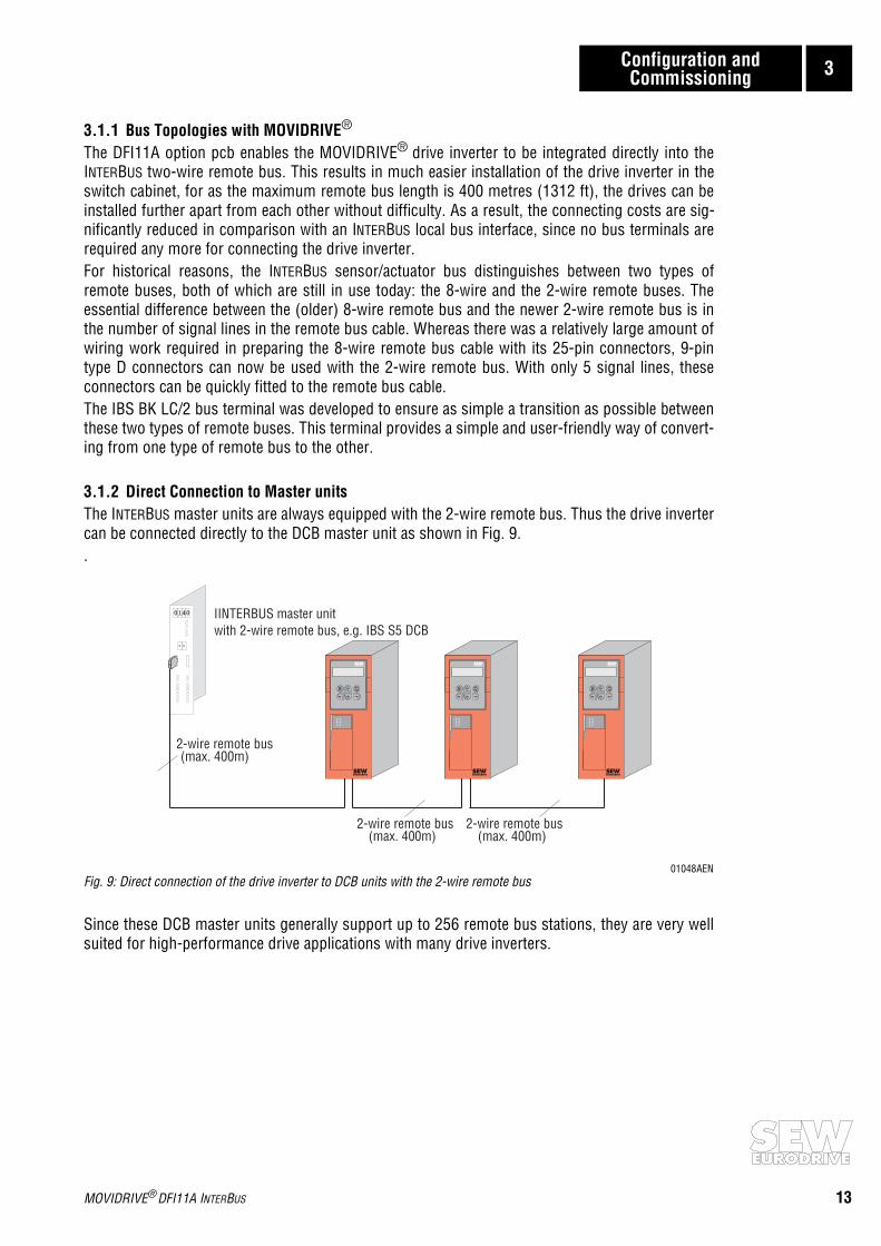
3.1.2 Direct Connection to Master unitsThe INTERBUS master units are always equipped with the 2-wire remote bus. Thus the drive invertercan be connected directly to the DCB master unit as shown in Fig. 9..
01048AENFig. 9: Direct connection of the drive inverter to DCB units with the 2-wire remote bus
Since these DCB master units generally support up to 256 remote bus stations, they are very wellsuited for high-performance drive applications with many drive inverters.
0140
- -
E QE QE Q
(max. 400m)2-wire remote bus
(max. 400m)2-wire remote bus
(max. 400m)2-wire remote bus
with 2-wire remote bus, e.g. IBS S5 DCBIINTERBUS master unit
MOVIDRIVE® DFI11A INTERBUS 13
14
3 Configuration and Commissioning
3.2 Drive Inverter Module Identity
With the DFI11A option, the MOVIDRIVE® is assigned the following Identity Code.Module Identity: 227dec = E3hex You must enter this Identity Code into the configuration list of the INTERBUS master unit.
3.3 Configuring the Master Module
To initialize the INTERBUS master unit, you must draw up various lists containing all the modulesconnected to the INTERBUS. These lists are made up of the following entries.• Process data length with Module Identity Code• Peripheral bus address• Input address• Output address• Group number (optional)• Communications reference (optional)The modules are shown in the configuration list in the order corresponding to their physical posi-tion in the INTERBUS. During the initialization of the bus system, the master module checks thedesigned bus configuration against the INTERBUS configuration read-in. If these configurations aredifferent, the bus system will not start. This situation is indicated by an appropriate error messageon the master module.There are three initialization options for a MOVIDRIVE® drive inverter with the DFI11A option.Which option is used depends on the process data length selected.While configuring, bear in mind that process data length 3 provides the most powerful applicationpotential for the MOVIDRIVE® drive inverter with INTERBUS. As a consequence of the direct inser-tion of process data into the I/O and/or peripheral area of the control system, you should generallyselect process data length 3 if your application concept is not yet complete and if you do not knowfor definite yet with which process data length the drive inverter is to be controlled.
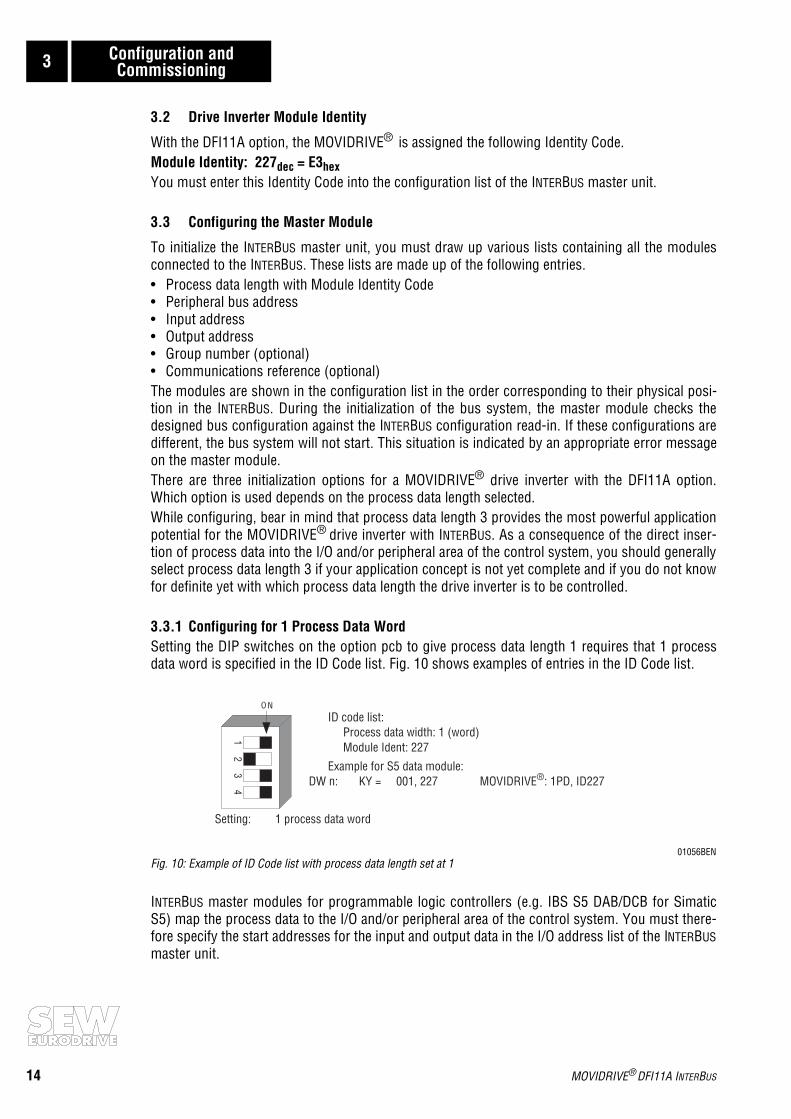
3.3.1 Configuring for 1 Process Data WordSetting the DIP switches on the option pcb to give process data length 1 requires that 1 processdata word is specified in the ID Code list. Fig. 10 shows examples of entries in the ID Code list.
01056BENFig. 10: Example of ID Code list with process data length set at 1
INTERBUS master modules for programmable logic controllers (e.g. IBS S5 DAB/DCB for SimaticS5) map the process data to the I/O and/or peripheral area of the control system. You must there-fore specify the start addresses for the input and output data in the I/O address list of the INTERBUSmaster unit.
O N
41
23
1 process data wordSetting:
DW n: KY = 001, 227 MOVIDRIVE : 1PD, ID227®Example for S5 data module:
Module Ident: 227Process data width: 1 (word)
ID code list:
MOVIDRIVE® DFI11A INTERBUS

Configuration and Commissioning 3
Fig. 11 shows an example of how the process data word transferred via INTERBUS is mapped in thecontrol system.
01051AENFig. 11: Process data word mapping in the PLC peripheral area
In this example, only one process data word is exchanged between the higher-level control systemand the drive inverter. With this configuration, for example, the drive inverter could be controlledusing Control Word 1 and Status Word 1 (see SEW Fieldbus Device Profile Manual documenta-tion). By specifying address 140 in both the input and output address lists, the process data wordis mapped to the peripheral word PW 140. The PLC access command will decide in this casewhether the process input data word (e.g. Status Word 1 of the drive inverter) is to be read with theload command L PW 140 or whether the process output data word (e.g. Control Word 1) is to bewritten with the transfer command T PW 140.You can read out the current process data configuration in the drive inverter in the P090 PDConfiguration menu item of the MX_SHELL user interface at any time. The MX_SHELL P090parameter will then read090 Fieldbus PD Configuration PARAM + 1 PDand thereby indicate that the current process data length is set at 1 PD and that the drive invertercan be parameterized via the PCP channel of the INTERBUS (Identification PARAM).
3.3.2 Configuring for 2 Process Data WordsSetting the DIP switches on the option pcb to give process data length 2 requires that 2 processdata words are specified in the ID Code list. Fig. 12 shows the requisite entries in the ID Code list.
01057BENFig. 12: Example of ID Code list with process data length set at 2
With this setting, the drive inverter uses two words in the peripheral area of the PLC.
PD 1
PD 1
PD 1
PD 1
PW 140
PW 140
E Q
PW
Input address for MOVIDRIVE : PW 140®
Output address for MOVIDRIVE : PW 140®
140L
140PWT
PLC address area
O N
41
23
Process data width: 2 (words)
DW n: KY = 002, 227 MOVIDRIVE : 2PD, ID227®Example for S5 data module:
Module Ident: 227Process data width: 2 (words)
ID-code list:
MOVIDRIVE® DFI11A INTERBUS 15

16
3 Configuration and Commissioning
Fig. 13 shows an example of how the process data words transferred by INTERBUS are mapped inthe control system.
01052AENFig. 13: Process data word mapping in the PLC peripheral area
In this example, two process data words are exchanged between the higher-level control systemand the drive inverter. With this configuration, for example, the higher-level control system couldsend the process output data Control Word 1 and Speed Setpoint to the drive inverter and read theprocess input data Status Word 1 and Speed Actual Value (see SEW Fieldbus Device Profile Manualdocumentation). By specifying address 140 in both the input and output address lists, the processdata words are mapped from peripheral word PW 140 onward. The PLC access command willagain decide whether the process input data words (e.g. Status Word and Speed Actual Value) areto be read or whether the process output data words (e.g. Control Word and Speed Setpoint) are tobe written. The MX_SHELL P090 parameter will then read090 Fieldbus PD Configuration PARAM + 2 PDand thereby indicate that the current process data length is set at 2 PD and that the drive invertercan be parameterized via the PCP channel of the INTERBUS (Identification PARAM).
3.3.3 Configuring for 3 Process Data WordsSetting the DIP switches on the option pcb to give process data length 3 requires that 3 processdata words are specified in the ID Code list. This configuration will allow you to implement verypowerful drive applications. Fig. 14 shows the requisite entries in the ID Code list.
01058BENFig. 14: Example of ID Code list with process data length set at 3
With this setting, the drive inverter uses three words in the peripheral area of the PLC.
PD 1
PD 1
PW 140
PW 140
L PW 140
T PW 140
PD 1 PD 2
PD 1 PD 2
PW 142
PW 142
PD 2
PD 2
E Q
Input address for MOVIDRIVE : PW 140®
Output address for MOVIDRIVE : PW 140®
PLC address area
O N
41
23
DW n: KY = 003, 227 MOVIDRIVE : 3PD, ID227®Example for S5 data module:
Module Ident: 227Process data width: 3 (words)
ID code list:
Setting: 3 process data words
MOVIDRIVE® DFI11A INTERBUS

Configuration and Commissioning 3
Fig. 15 shows an example of how the process data words transferred by INTERBUS are mapped inthe control system.
01053AENFig. 15: Process data word mapping in the PLC peripheral area
In this example, three process data words are exchanged between the higher-level control systemand the drive inverter. With this configuration, for example, the higher-level control system couldsend the process output data Control Word 1, Speed Setpoint and Process Ramp to the driveinverter and read the process input data Status Word 1, Speed Actual Value and Output Current.By specifying address 140 in both the input and output address lists, the process data words aremapped from peripheral word PW 140 onward. The PLC access command will again decidewhether the process input data words are to be read or whether the process output data words areto be written.The MX_SHELL P090 parameter will then read090 Fieldbus PD Configuration PARAM + 3 PDand thereby indicate that the current process data length is set at 3 PD and that the drive invertercan be parameterized via the PCP channel of the INTERBUS (Identification PARAM).
PD 1
PD 1
PD 1
PD 1
PW 140
PW 140
L PW 140
T PW 140
PD 2 PD 3
PD 2 PD 3
PW 142
PW 142
PD 2
PDD
2PW 144 P 3
PW 144 PD 3
E Q
Input address for MOVIDRIVE : PW 140®
Output address for MOVIDRIVE : PW 140®PLC address area
MOVIDRIVE® DFI11A INTERBUS 17

18
4 The PMS Interface
4 The PMS Interface
With the DFI11A option, the MOVIDRIVE® drive inverter offers a PMS (Peripherals Message Speci-fication) interface conforming to DIN 19245 Part 2. You can fully access all the drive parameters ofthe MOVIDRIVE® via this INTERBUS communications channel.
4.1 PMS Services
With the DFI11A option, the MOVIDRIVE® drive inverter supports the PMS services shown in Fig.16. For the adjustment of the drive inverter parameters, only the services INITIATE (establish link),READ, WRITE and ABORT (abort link) are of importance. Therefore, the remaining services will notbe discussed here. For further information please refer to the respective manuals for the INTERBUSmaster.
01054AXXFig. 16: PMS services supported by the MOVIDRIVE® drive inverter
4.1.1 InitiateWith the PMS service Initiate (establish link), a communications link is established between anINTERBUS master and the MOVIDRIVE® drive inverter.The establishment of the link is always performed by the INTERBUS master. As the link is beingestablished, various conventions regarding the communications link are checked, e.g. PMS ser-vices supported, user data length, etc. If the link is successfully established, the drive inverter willanswer with a positive Initiate Response.If the link could not be established, then the conventions regarding the communications linkbetween the INTERBUS master and MOVIDRIVE® drive inverter do not match. The drive inverter willanswer with an Initiate Error Response. In this event, compare the configured communicationsrelationship list of the INTERBUS master with that of the drive inverter (see Appendix A).The attempt to establish an already existing communications link again generally leads to Abort.The communications link will then no longer exist so the PMS service Initiate will have to beperformed a third time to reinstate the communications link.
I B MasterNTER US I B SlaveNTER US
Initiate
Abort
Abort/Reject
Identify
Get-OV
Status
Read
Write
I BNTER US
E Q
MOVIDRIVE® DFI11A INTERBUS

The PMS Interface 4
4.1.2 AbortAn existing communications link between the INTERBUS master and the MOVIDRIVE® drive inverteris cleared using the PMS service Abort. Abort is an unacknowledged PMS service and can beinitiated both by the INTERBUS master as well as by the MOVIDRIVE® . The attempt to establish an already existing communications link again generally leads to Abort.The communications link will then no longer exist so the PMS service Initiate will have to beperformed a third time to reinstate the communications link.
4.1.3 ReadWith the PMS service Read, the INTERBUS master can read all the communications objects (driveparameters) of the MOVIDRIVE® drive inverter. All drive parameters as well as their codes arelisted in detail in the MOVIDRIVE® Parameter List documentation.
4.1.4 WriteWith the PMS service Write, the INTERBUS master can write all the drive parameters of theMOVIDRIVE® . If a drive parameter is assigned an invalid value (e.g. value too high), the driveinverter generates a Write Error Response giving the precise cause of the error.
4.2 Object List
With the PMS services Read and Write, the INTERBUS master can access all the communicationsobjects defined in the object list.All drive parameters that can be accessed via the bus system are described as communicationsobjects in the static object list. All objects in the static object list are addressed via a fieldbus index.Table 2 shows the structure of the object list of the MOVIDRIVE® drive inverter.The index area is divided into three logical areas. The drive parameters are addressed with indicesfrom 8300 ... 9999dec. The parameter index can be obtained from the SEW MOVIDRIVE® Para-meter List documentation. Indices below 8300dec are handled directly by the option pcb andshould not be regarded as drive parameters of the inverter.
Table 2: Structure of the MOVIDRIVE® static object list
4.2.1 Object Description of the Drive ParametersThe drive parameters of the MOVIDRIVE® drive inverter are described in detail in the SEWMOVIDRIVE® Parameter List documentation. In addition to the parameter index, i.e. the numberwith which you can address the appropriate parameter via the communications interfaces of thedrive inverter, you will find further information about the coding, range of values and meaning ofthe parameter data.The object description in the object list is identical for all drive parameters. Even parameters thatcan only be read are given the attribute Read All/Write All in the object list, as the drive inverteritself carries out the appropriate testing and if necessary supplies a return code. Table 3 shows theobject descriptions of all drive parameters.
Parameter index (decimal) Designation of the communications object
8296 Download Parameter Block
8298 MOVILINK® parameter channel, cyclic
8299 MOVILINK® parameter channel, acyclic8300 ... 9999 Drive paramter for MOVIDRIVE® (can be addressed directly with READ/WRITE;
parameter index see SEW MOVIDRIVE® Parameter List documentation)
> 10 000 Table, program and variable memory addresses (these parameters can only be addressed via the MOVILINK® parameter channel)
MOVIDRIVE® DFI11A INTERBUS 19

20
4 The PMS Interface
Table 3: Object description of the MOVIDRIVE® drive parameters
4.2.2 “Download Parameter Block” ObjectThe “Download Parameter Block” object enables a maximum of 38 MOVIDRIVE® drive parametersto be written at the same time with a single Write service. This means you can use this object toparameterize the drive inverter in the start-up phase with only one Write service call. Since, as arule, only a few parameters have to be altered, this parameter block with a maximum of 38 para-meters is adequate for almost all applications. The user data area is fixed at 38 x 6 + 2 bytes = 230bytes (octet string type). Fig. 17 shows the structure of the “Download Parameter Block” object.
01345AENFig. 17: Structure of the “Download Parameter Block”
Index: 8300 ... 9999
Object code: 7 (Simple variable)
Data type index: 10 (Octet string)Length: 4
Local address: -
Password: -Access groups: -
Access rights: Read all / Write all
Name[16]: -Extension length: -
Byte
Octet 0:
Octet 1:
Octet 2:
Octet 3:
Octet 4:
Octet 5:
Octet 6:
Octet 7:
Octet 8:
Octet 9:
Octet 224:
Octet 225:
Octet 226:
Octet 227:
Octet 228:
Octet 229:
1 - 38 parameters
1st parameter
38th parameter
Data LSB
Data
Data
Data MSB
Index Low
Index High
Index Low
Index High
Data LSB
Data
DataData MSB
Index Low
Index High
Number of param.
Reserved (0)
MOVIDRIVE® DFI11A INTERBUS
The PMS Interface 4
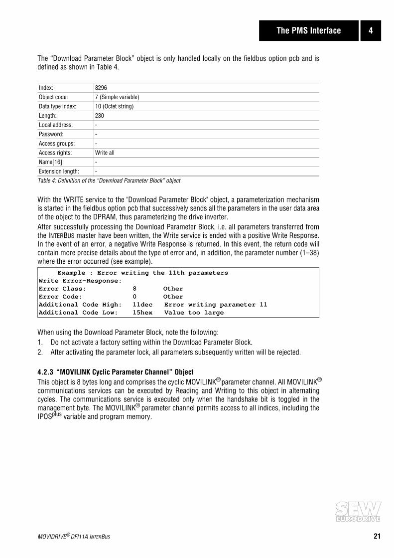
The “Download Parameter Block” object is only handled locally on the fieldbus option pcb and isdefined as shown in Table 4.
Table 4: Definition of the “Download Parameter Block” object
With the WRITE service to the "Download Parameter Block" object, a parameterization mechanismis started in the fieldbus option pcb that successively sends all the parameters in the user data areaof the object to the DPRAM, thus parameterizing the drive inverter.After successfully processing the Download Parameter Block, i.e. all parameters transferred fromthe INTERBUS master have been written, the Write service is ended with a positive Write Response.In the event of an error, a negative Write Response is returned. In this event, the return code willcontain more precise details about the type of error and, in addition, the parameter number (1–38)where the error occurred (see example).
When using the Download Parameter Block, note the following:1. Do not activate a factory setting within the Download Parameter Block.2. After activating the parameter lock, all parameters subsequently written will be rejected.
4.2.3 “MOVILINK Cyclic Parameter Channel” ObjectThis object is 8 bytes long and comprises the cyclic MOVILINK® parameter channel. All MOVILINK®
communications services can be executed by Reading and Writing to this object in alternatingcycles. The communications service is executed only when the handshake bit is toggled in themanagement byte. The MOVILINK® parameter channel permits access to all indices, including theIPOSplus variable and program memory.
Index: 8296Object code: 7 (Simple variable)
Data type index: 10 (Octet string)
Length: 230Local address: -
Password: -
Access groups: -Access rights: Write all
Name[16]: -
Extension length: -
Example : Error writing the 11th parametersWrite Error-Response:Error Class: 8 OtherError Code: 0 OtherAdditional Code High: 11dec Error writing parameter 11Additional Code Low: 15hex Value too large
MOVIDRIVE® DFI11A INTERBUS 21

22
4 The PMS Interface
Fig. 18 shows the structure of this communications object. For the structure of the parameterchannel please refer to the “MOVILINK® Communications Device Profile” Manual.
01236AENFig. 18: Structure of the “MOVILINK Cyclic Parameter Channel” object
The “MOVILINK Cyclic Parameter Channel” object is only handled locally on the fieldbus option pcband is defined as shown in Table 5.
Table 5: Definition of the “MOVILINK Cyclic Parameter Channel” object
Index: 8298
Object code: 7 (Simple variable)
Data type index: 10 (Octet string)Length: 8
Local address: -
Password: -Access groups: -
Access rights: Read all/Write all
Name[16]: -Extension length: -
Octet 0 Octet 1 Octet 2 Octet 3 Octet 4 Octet 5 Octet 6 Octet 7
4-byte dataParameter index
Manage-ment
Management
Reserved Indexhigh
Indexlow
DataMSB
Data Data DataLSB
Reserved
MOVIDRIVE® DFI11A INTERBUS

The PMS Interface 4
Fig. 19 shows the sequence of parameter access via the cyclic MOVILINK® parameter channel. Theinverter will only start executing the service when the master has toggled the handshake bit in theparameter channel. To do this, the master has to read the parameter channel at the beginning ofthe parameter adjustment in order to maintain the present status of the handshake bit in theinverter. The master can now initiate the evaluation of the parameter channel in the inverter bytoggling the handshake bit. The inverter will then execute the service coded in the parameter chan-nel and enter the service acknowledgement in the parameter channel. The master will receive theservice acknowledgement with the next Read access to the “MOVILINK Cyclic Parameter Channel”.
01237AENFig. 19: Sequence of the cyclic FMS services for parameter access with “MOVILINK Cyclic Parameter Channel”
4.2.4 “MOVILINK Acyclic Parameter Channel” ObjectThe “MOVILINK Acyclic Parameter Channel” object is 8 bytes long and comprises the MOVILINK®
parameter channel. This object can be used for acyclic parameter access, i.e. the drive inverter willexecute the service coded in the parameter channel each time it receives a WRITE service to thisobject. The handshake bit is not evaluated. Fig. 20 shows the structure of the “MOVILINK AcyclicParameter Channel”. communications object. For the structure of the parameter channel pleaserefer to the “MOVILINK® Communications and Device Profile” documentation.
01236AENFig. 20: Structure of the “MOVILINK Acyclic Parameter Channel” object
Higher Level Control System(Master)
READ 8298 (parameter channel)Data = Parameter channel
WRITE 8298 (parameter channel)OK
READ 8298 (parameter channel)Data = Parameter channel with result
MOVIDRIVE®
(Slave)
1. READ "MOVILINK Cyclic Parameter Channel" to evaluatethe status of the handshake bit.
2. Initiate execution of the service coded in the parameterchannel with WRITE to the "MOVILINK Cyclic ParameterChannel" object and toggling of the handshake bit
3. READ "MOVILINK Cyclic Parameter Channel" and evaluateservice acknowledgement in the parameter channel.
Octet 0 Octet 1 Octet 2 Octet 3 Octet 4 Octet 5 Octet 6 Octet 7
4-byte dataParameter index
Manage-ment
Management
Reserved Indexhigh
Indexlow
DataMSB
Data Data DataLSB
Reserved
MOVIDRIVE® DFI11A INTERBUS 23

24
4 The PMS Interface
When the drive inverter is parameterized via the acyclic MOVILINK® parameter channel, a distinc-tion is made between the following two operations:1) Parameter channel executes a Write service.2) Parameter channel executes a Read service.
1) Parameter channel executes a Write service
If a Write service is executed via the acyclic parameter channel (e.g. Write Parameter, Write Para-meter Volatile) the inverter will return the service acknowledgement for this service after it hasexecuted the service. If the Write access produces a fault, the corresponding fault code is returned.This variant has the advantage that by sending one WRITE MOVILINK® Parameter Channel theWrite services can be executed and the service be acknowledged by the evaluation of the FMSconfirmation (Fig. 21).
01238AENFig. 21: Execution of Write services via the acyclic MOVILINK® parameter channel
Higher Level Control System
WRITE 8299 (parameter channel)Service acknowledgement (OK/fault code)
MOVIDRIVE®
(Master) (Slave)
1. Initiate execution of the service coded in the parameterchannel with WRITE to the "MOVILINK Acyclic ParameterChannel object"
The WRITE service coded in theparameter channel is executedand the service acknowledgementimmediately returned as theresponse
MOVIDRIVE® DFI11A INTERBUS

The PMS Interface 4
2) Parameter channel executes a Read service
If a Read service is executed via the acyclic parameter channel, (e.g. Read Parameter, ReadDefault, etc.) the inverter will enter the read data in the parameter channel together with the serviceacknowledgement after the service has been executed. For the master to receive these data a PMS-READ access to the acyclic parameter channel must be executed. Therefore, to carry out Readservices via the parameter channel, a PMS-WRITE service followed by a PMS-READ service arerequired. Fig. 22 shows this sequence.
01239AENFig. 22: Execution of the Read services via the acyclic MOVILINK® parameter channel
The “MOVILINK® Acyclic Parameter Channel” object is only handled locally on the fieldbus optionpcb and is defined as shown in Table 2.
Table 6: Definition of the “MOVILINK Acyclic Parameter Channel” object
Index: 8299Object code: 7 (Simple variable)
Data type index: 10 (Octet string)
Length: 8
Local address: -Password: -
Access groups: -
Access rights: Read all / Write allName[16]: -
Extension length: -
WRITE 8299 (parameter channel)
READ 8299 (parameter channel)
OK
Service = Parameter channel with result
1. Initiate the execution of the service coded in the parameterchannel with WRITE to the "MOVILINK Acyclic ParameterChannel Object"
2. READ "MOVILINK Acyclic Parameter Channel" and evaluatethe service acknowledgement in the parameter channel
Receipt is confirmed immediately,parameter channel is evaluated andthe requested service executed.
Service acknowledgement is enteredin the parameter channel and can beevaluated in the Master with a READaccess.
(Master)MOVIDRIVE®
(Slave)Higher Level Control System
MOVIDRIVE® DFI11A INTERBUS 25

26 MOVIDRIVE® DFI11A INTERBUS
5 Parameter Setting Return Codes
5 Parameter Setting Return Codes
The return codes sent back by the drive inverter in the event of incorrect parameter setting aredescribed in detail in the Fieldbus Device Profile Manual and are not part of this documentation.However, the following special cases can arise in connection with INTERBUS.
5.1 Internal Communications Error
The return code shown in Table 7 is returned if a communications error has occurred between theoption pcb and the drive inverter system. It may be that the PMS service transferred via the field-bus was not executed and should be repeated. If this error recurs the drive inverter must beswitched off and then on again to reinitialize the unit.
Table 7: Return code if an internal communications error has occurred
Error Rectification:
Repeat the Read or Write service. If the error recurs, you should briefly disconnect the driveinverter from the mains supply and then switch it on again. If the error persists, consult the SEWService Department.
Code (dec) Meaning
Error class: 6 Access
Error code: 2 Hardware faultAdd. code high: 0 -
Add. code low: 0 -

MOVIDRIVE® DFI11A INTERBUS 27
Technical Data of the DFI11A Option 6
6 Technical Data of the DFI11A Option
Part no.: 822 723 3
Module Identity: 227 dec = E3 hex
Number of process data words:
Selectable via DIP switches: 1, 2 or 3 process data words
Setting as supplied: 2 process data words
MD0341BEFig. 23: Process data length setting in process data words
PCP channel:Parameter adjustment is supported with one PCP (Peripherals Communication Protocol) word.
PDU (Process Data Unit) size: 243 bytes
Connection system:
2-wire remote bus interface, with 9-pin type D connectors
Pin assignment to INTERBUS-S specification
Commissioning tools:
MX_SHELL software
DBG11 control keypad
ON
12
34
1 2
OFF OFF 3PDOFF ON 2PDON OFF 1PDON ON -----
Setting as supplied: 2PD

28
Appendix A
Appendix A
Table 8 shows the communications relationship list (CRL) for the MOVIDRIVE® drive inverter.When configuring the INTERBUS master (client) remember to adjust the PDU size Send LoPrio =243 entry. For an explanation of the individual CRL data please refer to DIN 19245 Part 2.
Table 8: INTERBUS CBL for MOVIDRIVE® with DFI11A option
KR Type ATTR RADR SCC RCC SAC RAC ACI/CCI
0 MMAZ D 0 1 1 1 1 0
Max PDU Size: Features supported Supported PMS service
Send HiPrio 0 00 00 00 00 80 30 Get-OV.indicationRead.indicationWrite.indication
Send LoPrio 243
Rec. HiPrio 0
Rec. LoPrio 243
Max. number of outstanding client services: 1
Max. number of outstanding server services: 1
Type of communication: Connection oriented
MOVIDRIVE® DFI11A INTERBUS

Appendix B
Appendix B
Connection to DAB Master Units
First generation INTERBUS-S diagnostics interfaces (DAB), e.g. the IBS S5 DAB module for SimaticS5, only support the old 8-wire remote bus with a 25-pin type D connector. MOVIDRIVE® driveinverters are connected by using an IBS BK LC/2 bus terminal. This bus terminal facilitates the con-version from the old 8-wire remote bus to the new 2-wire system. Fig. 24 shows the connection ofthe MOVIDRIVE® drive inverters to the DAB units. A standard cable for the 8-wire remote bus isemployed from the DAB master unit to the bus terminal. The connection from the bus terminal tothe drive inverter is made by means of an adapter cable from 25-pin type D to 9-pin type D.
01049AENFig. 24: Connection of the drive inverter to DAB master units via the IBS BK LC/2 bus terminal
When using DAB master units, care should be taken not to exceed the maximum number of remotebus stations. These master modules with their 8-wire remote bus interface generally support up to64 remote bus stations. For more detailed information please refer to the master unit documenta-tion.
0 1 4 0
- -
IN OUT
IBS BKIBS BKLC/2
E QE QE Q
(max. 400m)2-wire remote bus
(max. 400m)2-wire remote bus
(max. 400m)2-wire remote bus
8-connector remotebus (max. 400 m)
with 8-wire remote bus, e.g. IBS S5 DABINTERBUS master unit
MOVIDRIVE® DFI11A INTERBUS 29

30
Appendix B
Integration in 8-Wire Remote Bus Systems
Conversion from both the 8-wire to the 2-wire remote bus, as well as from the 2-wire to the 8-wireremote bus, is achieved using the IBS BK LC/2 bus terminal. This means, for example, thatMOVIDRIVE® drive inverters can be integrated into existing INTERBUS networks employing the old8-wire remote bus. Fig. 25 shows the integration options in an already existing system with an 8-wire remote bus.
01050AENFig. 25: Integrating MOVIDRIVE® drive inverter into existing 8-wire remote bus systems
MOVIDRIVE® drive inverters can be integrated into the existing INTERBUS system at any point bysplitting the 8-wire remote bus. This is done by feeding the incoming 8-wire remote bus to an IBSBK LC/2 bus terminal. Using an appropriate adapter cable, you can now connect the firstMOVIDRIVE® drive inverter to the bus terminal and then network all the other drive inverters usingthe standard 2-wire remote bus cable.
A further IBS BK LC/2 bus terminal must then be connected following the last drive inverter. Thishandles the conversion back to the 8-wire remote bus. The two local bus interfaces of the newlyinserted bus terminals may also be used, of course.When extending an already existing INTERBUS 8-wire remote bus system, bear in mind that mas-ter units with 8-wire remote bus interfaces generally support only 64 remote bus stations. Formore detailed information please refer to the master unit documentation.
INOUT
IBS BKLC/2
IN OUT
IBS BKLC/2
E QE QE Q bus terminalIBS BK LC/2
(max. 400m)2-wire remote bus8-wire remote bus
(max. 400m)2-wire remote bus
8-wire remote busonward
8-wireremote bus
8-wire remote busIncoming
bus terminalIBS BK LC/2
MOVIDRIVE® DFI11A INTERBUS

Index
MOVIDRIVE® DFI11A INTERBUS 31
Index
BBus topologies 13
CCommissioning 11Communications interface 18Configuration 11
DDAB master units 29DCB master units 13Diagnosis
INTERBUS application, see Fieldbus Communications Profile Manual
with the option pcb LEDs 10Display elements 10Download parameter block 20
EEquipotential bonding 8
FFieldbus interface documentation 4Fitting the option pcb 6
IIdentity Code 14Installation
of the INTERBUS system 7
LLEDs 10
MModule Identity 14MOVIDRIVE settings
Terminal assignment for fieldbus mode 12
PParameter setting
Abort 19Download Parameter Block 20Error 26Initiate 18of the drive parameters 19Read 19Services 18Write 19
Pin Assignment 7PMS interface 18Process data length 9
1 PD 142 PD 153 PD 16Setting as supplied 9
RRead 19Remote bus
8-wire remote bus 30Return codes 26
WWrite 19