T III CNC machine operator I - Holzbau …€¦ · Project part III CNC technology: machine...
75
supported by: Berufsförderungswerk des Hessischen Zimmerhandwerks e. V. bubiza.de CNC Technology Machine operator I Development of a collection of reference materials containing course templates and course materials with the goal to include the latest CNC technology in the area of Wood Building & Construction Establishment of a Centre of Competence for the Carpenter and Wood Building Profession through extension of the Centre for Carpenters in Kassel, Germany
Transcript of T III CNC machine operator I - Holzbau …€¦ · Project part III CNC technology: machine...
supported by:Berufsförderungswerkdes HessischenZimmerhandwerks e. V.bubiza.de
CNC Technology
Machine operator I
Development of a collection of reference materials containing course templates and
course materials with the goal to include the latest CNC technology in the area of Wood
Building & Construction
Establishment of a Centre of Competence for the Carpenter and Wood Building Profession
through extension of the Centre for Carpenters in Kassel, Germany

Project part III CNC technology: machine operator I 2
1 Table of Contents
1 Table of Contents .................................................................................................
2 Introduction ............................................................................................................
3 Safety Regulations and Procedures .......................................................................
3.1 General safety regulations of the WBC ..................................................................
3.2 Basic safety rules of the Centre for Advanced Wood Processing ..........................
3.3 General “housekeeping” practices .........................................................................
3.4 Additional safety guidelines for the Hundegger K2 ................................................
3.5 Emergency procedures of the CAWP ....................................................................
3.6 Description of the lockout procedure ......................................................................
3.7 Introduction to the safety features of the K2........................................................
4 Description of the main components and tool aggregates of the K2 ……..……….
4.1 Machine Components of the Hundegger K2 at UBC ............................................ .
5 Operating the Machine using The Single Piece Construction Program (SPCP) of Hundegger ............................................................................................................ .
5.1 Manual Operation Mode in the SPCP .................................................................. .
5.2 Machine Data .........................................................................................................
5.3 Create and Maintain an Operator Profile .............................................................. .
5.4 Create a job and list the components .................................................................... .
5.5 Job List, Cut List and Processed Part List
5.6 Optimize Timber when machining different length work pieces
6 Tool Changes and Adjustments ............................................................................. .
6.1 Frequent Error Messages and Troubleshooting
7 Machine Maintenance, Oils and Fluids ................................................................. .
7.1 General Maintenance ............................................................................................ .
8 Lists ....................................................................................................................... .
8.1 Lists and Layout…………………………………………………………………
Project part III CNC technology: machine operator I 3
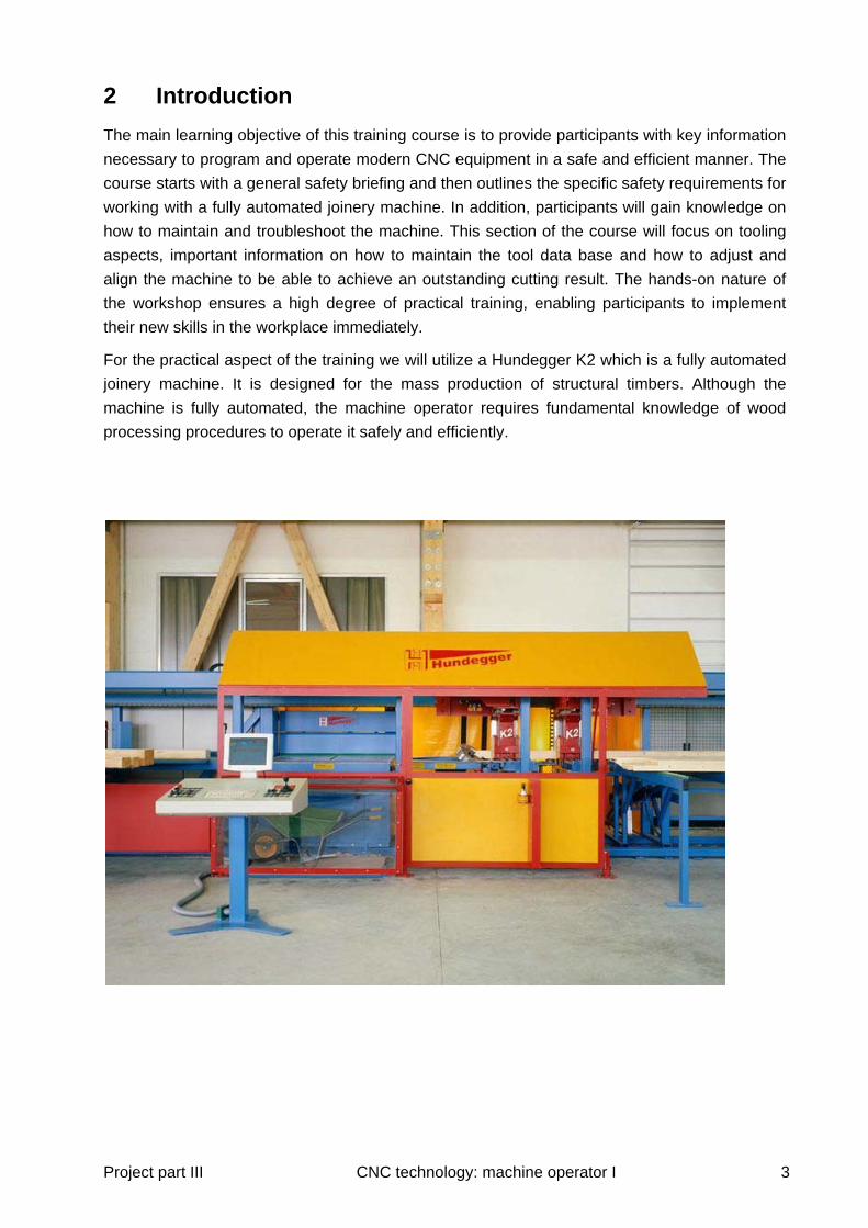
2 Introduction
The main learning objective of this training course is to provide participants with key information
necessary to program and operate modern CNC equipment in a safe and efficient manner. The
course starts with a general safety briefing and then outlines the specific safety requirements for
working with a fully automated joinery machine. In addition, participants will gain knowledge on
how to maintain and troubleshoot the machine. This section of the course will focus on tooling
aspects, important information on how to maintain the tool data base and how to adjust and
align the machine to be able to achieve an outstanding cutting result. The hands-on nature of
the workshop ensures a high degree of practical training, enabling participants to implement
their new skills in the workplace immediately.
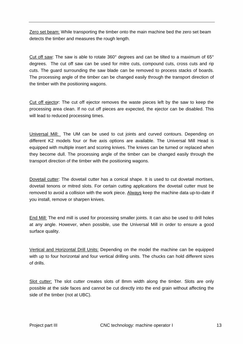
For the practical aspect of the training we will utilize a Hundegger K2 which is a fully automated
joinery machine. It is designed for the mass production of structural timbers. Although the
machine is fully automated, the machine operator requires fundamental knowledge of wood
processing procedures to operate it safely and efficiently.

Project part III CNC technology: machine operator I 4
3 Safety Regulations and Procedures
3.1 General safety regulations of the WCB (Worker’s Compensation
Board of British Columbia)
The WCB safety regulations have to be respected! This includes the wearing of appropriate
footwear, eye and ear protection! Gloves have to be worn during tool maintenance and while
handling sharp objects.
Foot wear: Working with heavy timbers requires steel-toed leather boots. It is mandatory to
wear steel-toed shoes working in the machine laboratory at CAWP.
Eye protection: Proper eye protection should be worn when there is a chance machine
operators will be exposed to flying particles or other forms of harmful material. Three types of
eye and face protection are safety glasses, goggles and face shields.
If you wear contact lenses, immediately notify your employer. Be aware that WCB regulations
prohibit you from wearing them under certain conditions.
Hearing Protection: You must guard yourself against very loud, prolonged noise or sharp,
impact noise, as both can permanently damage your hearing. Only ear muffs or plugs reduce
loud noise to a safe level. Cotton stuffed in your ears is useless.
Hand Protection: Wear leather or vinyl-coated gloves when you handle rough boards, rough
metal or sharp objects like saw blades, mills or drills. However, do not wear gloves while
machining such materials.

Project part III CNC technology: machine operator I 5
3.2 Basic safety rules of the Centre for Advanced Wood Processing
BASIC SAFETY RULES - MACHINE LABORATORY
CENTRE FOR ADVANCED WOOD PROCESSING
Welcome to the Centre for Advanced Wood Processing, Machine Laboratory. In
order to maintain a safe environment for all those wishing to use these facilities, the
following basic rules must be observed.
Eye protection must be worn at all times while using equipment, assisting or observing the use of equipment
Hearing and dust protection must be used when appropriate Steel-toed boots must be worn when working in the machine lab Machinery must be locked out or disconnected from the power source before
changing tooling or performing maintenance on any equipment No loose clothing or neck ties, shirt sleeves to be rolled up No jewellery or rings Long hair must be tied back No food or drink Absolutely no horse play No unnecessary loud noises or yelling. This can startle or distract personnel
operating dangerous machinery Always use guards and safety devices while working on machinery as indicated
by the instructor Work areas must be kept clean and free of debris to prevent tripping or slipping
hazards Dust collection must be used when machining or sanding Never work alone Never use compressed air to clean machines, clothing or yourself Room / machinery must be booked in advance Report any malfunctioning equipment or tools to the Instructor, Lab Technician
or Facility Manager
ALL USERS MUST CLEANUP AFTER THEMSELVES.
Allow 15 minutes at the end of a work session to dust equipment used as well as any surrounding equipment which dust has settled on. Pickup scrap / garbage and dispose of in provided scrap bins or garbage cans. Thoroughly sweep work areas. Return all equipment to the appropriate storage area.

Project part III CNC technology: machine operator I 6
3.3 General “housekeeping” practices
The shop or plant work area should be neat and orderly at all times. Dirty, cluttered
3.3 General “Housekeeping” Practices
The following are general rules:
1. Clean your workstation at the end of each class period or job shift.
2. Put stock away promptly after using it.
3. Keep windows, light bulbs, reflectors and walls bright, but without glare. Replace burned-out bulbs at once. Good lighting is essential to safe working conditions.
4. Make sure fire extinguishers are accessible and in working order. Know how to use them.
5. Know the fire regulations pertaining to your shop,
6. Put oily rags and other used combustible materials in a covered metal container.
7. Keep paints, chemicals and other flammable substances in approved metal storage cabinets.
8. Be sure air hoses and electrical cords do not pose a tripping hazard.
9. Stack lumber in straight, neat piles. Proper stacking not only makes the shop safer but it also prevents warping.
10. Strap down large loads of lumber to prevent them from toppling.
11. Check to ensure that openings in a building floor have guardrails (1.070 mm or 42 inches) or higher, and that there is an additional rail between them. Alternatively, the holes should be covered and the covers nailed down to prevent removal or movement.
12. Look for signs that alert you to hazards.
13. Use a hard brush to clean benches and machinery.
14. Ensure that the power is shut off before you clean machinery.
15. To avoid damage, store hard hats, goggles and face shields in a safe place when they are not in use.
16. Do not allow your toolbox to become a tripping hazard.
17. Make sure stretchers and blankets are kept in the areas where, by WCB regulations, they are required to be stored.
18. Clean portable equipment before you store it.
19. Do not allow tools to protrude over the edge of a table or bench.
20. Use a vacuum cleaner to remove dust from floors or confined areas. Never use an air hose for this purpose, as serious lung problems can result. In addition, all you do is transfer the dust to another area.
21. Never use an air hose to remove dust from your clothing.
22. Remove lumber with protruding nails from the floor area. Pull out the nails and discard them, along with unusable short stock, in a disposal bin. Failure to take these measures can result in foot injuries.
23. Avoid moving backwards when you carry a heavy load. If you must step back, check the area for hazards before doing so.

Project part III CNC technology: machine operator I 7
24. Do not store items on top of machines.
25. Make sure the air pressure hose you use has a safety nozzle.
26. Do not use machinery with unguarded or inadequately guarded moving parts.
3.4 Additional safety guidelines for the Hundegger K2
Note: Always follow the instructions and guidelines in the user manual provided by the machine
manufacturer. The points below are samples of those guidelines.
It is prohibited to disable the security devices or to use the machine with damaged
security devices.
It is forbidden to make software changes or to program speeds greater than the
specified maximum speed of chucks or tools.
Do not use cell phones or devices emitting electromagnetic signals within a radius of 2
meters.
Naked flames, smoking and the use of highly flammable or explosive products are not
allowed.
The intake of alcohol or drugs before and while using the machine is forbidden.
3.5 Emergency procedures of the CAWP
Major Accidents/Injuries
Call EMERGENCY at “911”
Specify whether you need Police, Ambulance or Fire
Give your location as:
Centre for Advanced Wood Processing
Forest Sciences Centre
2424 Main Mall
Room # 1935
The South West Corner of Agronomy Road and East Mall
Phone: (604) 822-8276

Project part III CNC technology: machine operator I 8
Minor Accidents or Illness
For minor cuts requiring only a band aid, there is a first aid kit available in the System
Simulation Laboratory. For more serious injuries proceed to Emergency First Aid at the
Student Health Service in the Acute Care Unit (weekdays 8:00 am to 4:00 pm, phone 2-7011) or
phone 2-4444 for industrial first aid (24 hours, 7 days per week). After hours and on weekends
you can also call the Industrial First Aid attendant at Parking and Security (2-2222). Patrol will
provide transportation for victims of minor accidents or illness to the First Aid room in the
Student Health Services or to the Emergency Department.
Fire/Explosion
Pull FIRE ALARM (PULL STATION)
Dial “911” and state your name
Give the Address:
Centre for Advanced Wood Processing
Forest Sciences Centre
2424 Main Mall
Room # 1935
The South West Corner of Agronomy Road and East Mall
Phone: (604) 822-8276
Provide information about the fire (i.e. what floor, how fast the fire is spreading, people trapped,
etc.)
If possible control fire with available fire extinguishing equipment.
If fire cannot be controlled, isolate it by CLOSING THE DOORS. Do not lock the doors.
Leave by the nearest safe exit. Walk, don’t run. Shut doors behind you.
Wait outside the main entrance of the building to inform Fire Department of location of fire. All
others should move well away from the building.
Assist in the evacuation of the building if requested to do so.
Do not re-enter building until permission is received from the Fire Department.

Project part III CNC technology: machine operator I 9
3.6 Description of the lockout procedure
The purpose of plant lockout procedures is to ensure that through proper instruction and plant practices, all energy-activated equipment is safe. The plant lockout procedure ensures that no equipment is started inadvertently.
1. In accordance with WCB Regulation 16.000 and 16.102, before cleaning, repairing or adjusting any power-activated equipment, all employees who have been authorized to perform these duties must lock the machine out. If starting that machine could constitute a hazard to the employee or others, he or she must, without fail, cut off the power supply at the main manual control and lock it out. There is one exception to this rule:
Where, in the best judgment of the authorized person in charge, work on moving or energized equipment cannot be avoided.
This includes all related equipment.
2. After lockout, the worker must check to ensure the machine cannot be started by pushing the “start” button.
3. Each worker must lock out for himself, using his or her own lock (which can be identified). Under no circumstances are locks to be borrowed.
4. If in doubt about the location of a power source, call the supervisor.
5. After work has been completed, each worker shall remove only his or her own lock.
6. Any worker forgetting to remove his or her lock may be called in at any time to remove it, at the individual’s own expense.
7. The only time a lock may be removed by another person is:
(a) When every effort has been made to contact the worker
(b) After physical check by the foreman and a job steward or safety committee member
(c) After everyone is satisfied that the equipment is safe to operate
8. The removal of the last lock is a serious act. Before the last lock has been removed, the person responsible for restarting the equipment must ensure that all persons are in the clear.
9. Other sources of energy: Electrical power is not the only source of energy that can cause accidents if inadvertently operated. Compressed air (and other gases), hydraulics, and gravity are some examples of energy sources that must be isolated, blocked, or dissipated and secured (that is, locked out) before physical contact is required on equipment. The employees involved must be trained to understand that lockout of the above energy sources is also required.
Lockout procedures shall apply to all plant personnel. This includes office staff, production employees, supervisory staff, maintenance personnel, and outside contractors.

Project part III CNC technology: machine operator I 10
3.7 Introduction to the safety features of the K2
Before operating the Hundegger K2, the operator must make sure that the following safety
devices are in the correct position and operating properly. It is important that the operator has
read and understood the user manual before operating the machine. The manual should be
stored easily accessible at the machine as reference material.
1) Turn the safety switch, located at the back of the machine, to the “on” position. The
safety switch connects the circuit cabinet to the 110VAC circuit and the 480VAC circuit.
2) Turn the two main circuit breakers, positioned by the circuit cabinet at the back of the
machine, to the “On” position. The first circuit breaker connects the circuit cabinet and
the controller cabinet to the 110VAC circuit. The second circuit breaker connects the
circuit cabinet to the 480VAC circuit.
3) Make sure that no one is behind the machine and close all of the safety gates. The
safety gates are equipped with sensors that activate the emergency stop circuit if the
gates are open.
4) Make sure that the safety doors of the circular saw and the Universal Mill are closed.
These gates are equipped with emergency stop sensors as well.
5) Make sure that no one is behind the light barrier at the out feed table and that the light
barrier works properly. Saw dust or wood fragments can prevent the light barrier from
working properly. Crossing the light barrier activates the emergency stop mechanism.
The light barrier is also tripped if the door of the Universal Mill is open.
6) When machining longitudinal processes like hip- or valley cuts make sure that no one is
in the danger zone at the extension of the machine table. Pieces of wood can be
thrown out of the machine and may cause serious injury!
7) Press the “Machine On” button. This activates the power supply and starts the
computer system on the operator console. Avoid using the “Machine Off” button for
emergency stops as this action causes a system crash! Instead, use the emergency stop
button for emergency stops and the “End windows” function in the job-menu of the
SPCP to initiate the shutdown of the computer system properly.
8) Pull up the “Emergency Stop” button at the operator console. The emergency stop
circuit immediately interrupts all moving functions and the power supply when the
emergency stop button is pushed. It does not interrupt the control system. Processing
can be restarted by pulling up the emergency stop button and pressing the “Machine
On” button.

Project part III CNC technology: machine operator I 11
4 Description of the main components and tool
aggregates of the K2
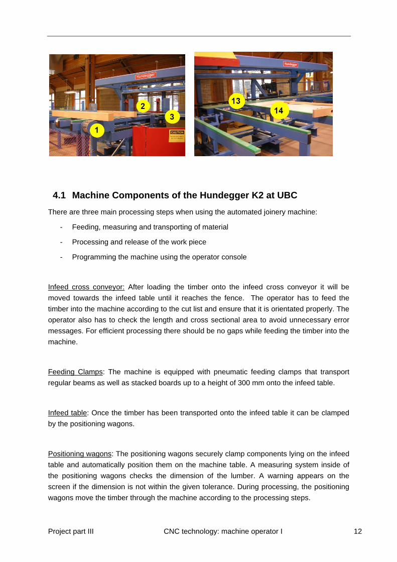
(1) Infeed cross conveyor
(2) Feeding clamps
(3) Infeed table
(3a) Zero set beam
(4) Operator console
(5) Cut off saw
(6) Cut off ejector
(7) Universal Mill
(8) Positioning wagons
(9) Horizontal and vertical drill
supports
(10) Slot cutter
(11) Marker
(12) Rotator
(13) Ejector Guide
(14) Out-feed table
Project part III CNC technology: machine operator I 12
4.1 Machine Components of the Hundegger K2 at UBC
There are three main processing steps when using the automated joinery machine:
- Feeding, measuring and transporting of material
- Processing and release of the work piece
- Programming the machine using the operator console
Infeed cross conveyor: After loading the timber onto the infeed cross conveyor it will be
moved towards the infeed table until it reaches the fence. The operator has to feed the
timber into the machine according to the cut list and ensure that it is orientated properly. The
operator also has to check the length and cross sectional area to avoid unnecessary error
messages. For efficient processing there should be no gaps while feeding the timber into the
machine.
Feeding Clamps: The machine is equipped with pneumatic feeding clamps that transport
regular beams as well as stacked boards up to a height of 300 mm onto the infeed table.
Infeed table: Once the timber has been transported onto the infeed table it can be clamped
by the positioning wagons.
Positioning wagons: The positioning wagons securely clamp components lying on the infeed
table and automatically position them on the machine table. A measuring system inside of
the positioning wagons checks the dimension of the lumber. A warning appears on the
screen if the dimension is not within the given tolerance. During processing, the positioning
wagons move the timber through the machine according to the processing steps.
Project part III CNC technology: machine operator I 13
Zero set beam: While transporting the timber onto the main machine bed the zero set beam
detects the timber and measures the rough length.
Cut off saw: The saw is able to rotate 360° degrees and can be tilted to a maximum of 65°
degrees. The cut off saw can be used for mitre cuts, compound cuts, cross cuts and rip
cuts. The guard surrounding the saw blade can be removed to process stacks of boards.
The processing angle of the timber can be changed easily through the transport direction of
the timber with the positioning wagons.
Cut off ejector: The cut off ejector removes the waste pieces left by the saw to keep the
processing area clean. If no cut off pieces are expected, the ejector can be disabled. This
will lead to reduced processing times.
Universal Mill: The UM can be used to cut joints and curved contours. Depending on
different K2 models four or five axis options are available. The Universal Mill Head is
equipped with multiple insert and scoring knives. The knives can be turned or replaced when
they become dull. The processing angle of the timber can be changed easily through the
transport direction of the timber with the positioning wagons.
Dovetail cutter: The dovetail cutter has a conical shape. It is used to cut dovetail mortises,
dovetail tenons or mitred slots. For certain cutting applications the dovetail cutter must be
removed to avoid a collision with the work piece. Always keep the machine data up-to-date if
you install, remove or sharpen knives.
End Mill: The end mill is used for processing smaller joints. It can also be used to drill holes
at any angle. However, when possible, use the Universal Mill in order to ensure a good
surface quality.
Vertical and Horizontal Drill Units: Depending on the model the machine can be equipped
with up to four horizontal and four vertical drilling units. The chucks can hold different sizes
of drills.
Slot cutter: The slot cutter creates slots of 8mm width along the timber. Slots are only
possible at the side faces and cannot be cut directly into the end grain without affecting the
side of the timber (not at UBC).
Project part III CNC technology: machine operator I 14
Marker: The metal scribe vertically scores the lumber according to the layout of the beam.
These lines are used to mark the butt joints of timbers and important connection points.
Rotator: The rotator turns the timber by 90°. To ensure that the length position of the beam
is maintained during this process, the timber is held in place by both positioning wagons
before and after the rotation. The number of rotations substantially impact the processing
time!
Ejector Guide: Once the cutting process is completed the stock is moved by the positioning
wagons to the out feed table. After the positioning wagons release the work piece and clear
the area, the ejector guide pushes the work piece towards the out feed storage table.
5 Operating the machine using the Single Piece
Construction Program (SPCP)
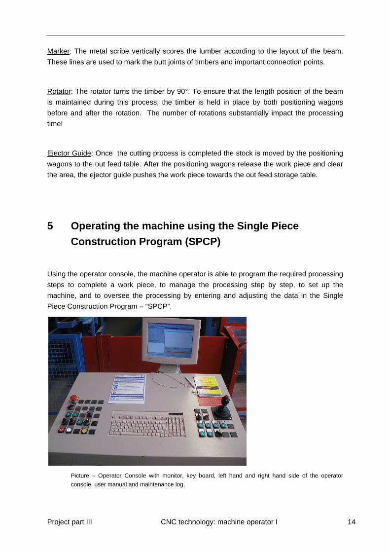
Using the operator console, the machine operator is able to program the required processing
steps to complete a work piece, to manage the processing step by step, to set up the
machine, and to oversee the processing by entering and adjusting the data in the Single
Piece Construction Program – “SPCP”.
Picture – Operator Console with monitor, key board, left hand and right hand side of the operator
console, user manual and maintenance log.

Project part III CNC technology: machine operator I 15
Picture – opened up operator console
This section is meant to provide an overview of the Single Piece Construction Program
(SPCP) of the Hundegger machine. For detailed descriptions of the functions see the “SPCP
help” available in the “help menu” of the Hundegger software.
Below is a description of the buttons/switches of the machine:
The buttons at the left hand side of the operator console:
Emergency stop When pressed, the machine comes to a standstill.
The current status is retained. After pulling it up and
pressing “Start” the program flow continues.
Light Switch Turns the light in the machine on/off (not at UBC)
Positioning wagons left/ right The button for the corresponding positioning wagon
has to be pressed to clamp/unclamp and to move
the positioning wagon with the joystick.
Additional vertical clamp During processing the part is additionally pressed
onto the machine table by the vertical clamps.
Potentiometer (saw) Regulates the cutting speed of the saw.
Potentiometer ( Processing
speed)
Use during processing to optimize the processing
speed while maintaining outstanding cutting results.
Cut off ejector manual Press and hold the button to operate the cut off
ejector manually
Clear off front cuts Can be switched off if the initial cut off on the beam
Project part III CNC technology: machine operator I 16
is less than 6mm (blade kerf). Increases processing
time.
Machine off Switches the machine off (including the PC)
Machine on Switches the machine/PC on. The button lights up.
Reset General reset. Reinitializes the machine
The buttons at the right hand side of the operator console:
Loading conveyor
forward/ backward
(manual operation)
Operates the infeed cross conveyor.
Loading conveyor
(automatic)
Joystick
Off: Stops the automatic delivery sequence
On: The infeed cross conveyor is operated as long as
no part is detected by the sensor in the part waiting
position
Controlls the positioning wagons
Load timber: Brief
pressure
The part is automatically transported from the infeed
cross feeder onto the infeed table
Load timber: Long
pressure
Feeding clamps move a timber back onto the infeed
cross conveyor
Rotate timber Beam is rotated by 90°. Attention: The beam should be
clamped by both positioning wagons before rotating
Eject timber Operates the ejector guide
Start Automatic mode: Program start
Manual mode: Positions the selected aggregate
Operate Automatic mode: Brief pressure cancels the operation,
long pressure extends the operation to maximum
stroke.
Manual mode: Operate the saw or any other tool that is
selected in the manual operation window.
Stop after processing After the current process the sequence is stopped.
Project part III CNC technology: machine operator I 17
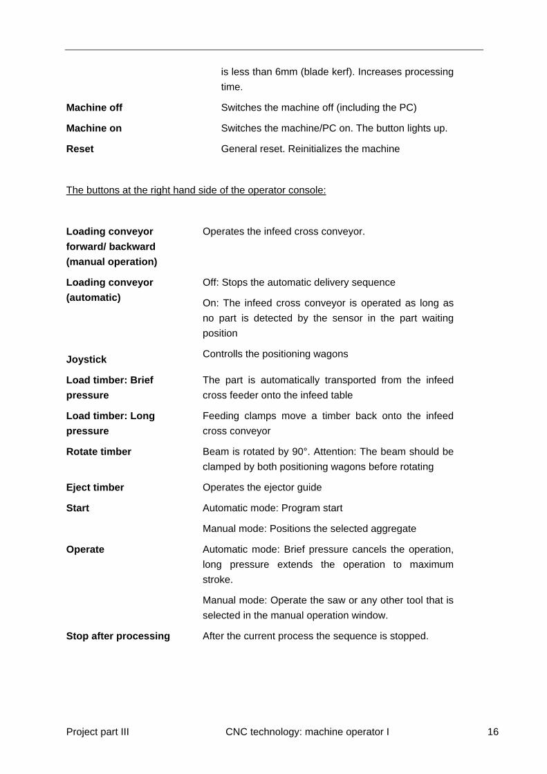
Picture – The data can be transferred via the disk drive on the side of the machine, via the network or by
using USB sticks.
Many of the most important commands in the SPCP can be executed by using short cut
keys. Below are some examples for frequently used functions. The key combinations can be
found behind the commands in the menu.
* Transfers the highlighted work piece to the cutting list
A Opens the screen for Manual Operation
B Shows the PLC Data/Processing list
D Opens the screen for Machine Data
5.1 Manual Operation mode in the SPCP
The tools can be positioned and operated individually in the Manual Operation Mode
(accessible with the “A” button).
There are two ways to position a tool:
1) Check the appropriate box for the positioning parameter that needs to be changed,
press F2, enter the required value for the parameter, press enter and press start.
2) To position the tool check the positioning parameter that needs to be changed and
use the joystick as indicated in the help section on the top right hand corner of the
manual operation screen.
Project part III CNC technology: machine operator I 18
How to operate the tools with the “Operate” button:
The saw, slot cutter and drills spin and strike as long as the button is pushed.
The Universal Mill spins as long as the button is pressed, even during positioning.
Depending on the machine type the positioning wagons need to be calibrated. To develop a
better understanding of the machine, the operator should run the machine in manual mode.
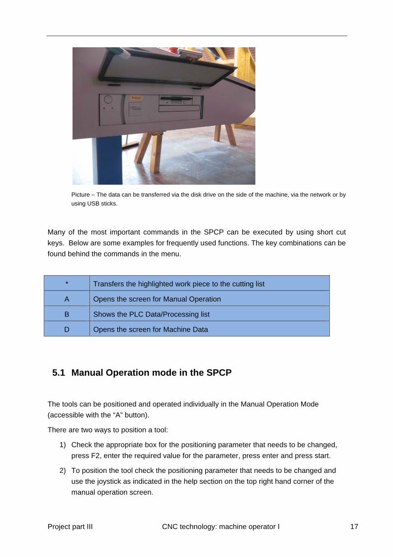
Exercise 1: Manual transport of a work piece
Execute the following process: The work piece is moved onto the infeed table, it is ready
to be clamped by the positioning wagons and moved to the ejector guide. After the
positioning wagons release the work piece, the ejector pushes it towards the outfeed storage
table. Reverse the process and move the work piece with the positioning wagons from the
out feed table to the infeed table where it will be ejected.
Picture: Student executing the first exercise (manual transport of work piece)
During this exercise measurements can be taken (length of the work piece).
Exercise 2:
Execute the following process: A work piece with a length of approximately 2 m which has
been marked in the middle with a pen (marking faces away from the operator) has to be
moved onto the infeed table and using the rotator, the piece is turned until the markings face

Project part III CNC technology: machine operator I 19
the machine operator. The positioning wagons place the work piece at the saw where it will
be cut into two pieces at the marking. Both pieces are ejected at the trim saw.
Picture: Manual operation – cut work piece
Move aggregate:
By selecting the manual operator mode from the menu the appropriate axis can be moved
with the joystick. The speed of the movement can be regulated by tilting the joystick more.
This function is also used in manual mode to adjust the aggregates and to move them to
certain positions e.g. for a tool change.
Exercise 3:
Execute the following process: Use the arrow button to select the various aggregates and
move those with the joystick. Which angles cannot be controlled?
Project part III CNC technology: machine operator I 20
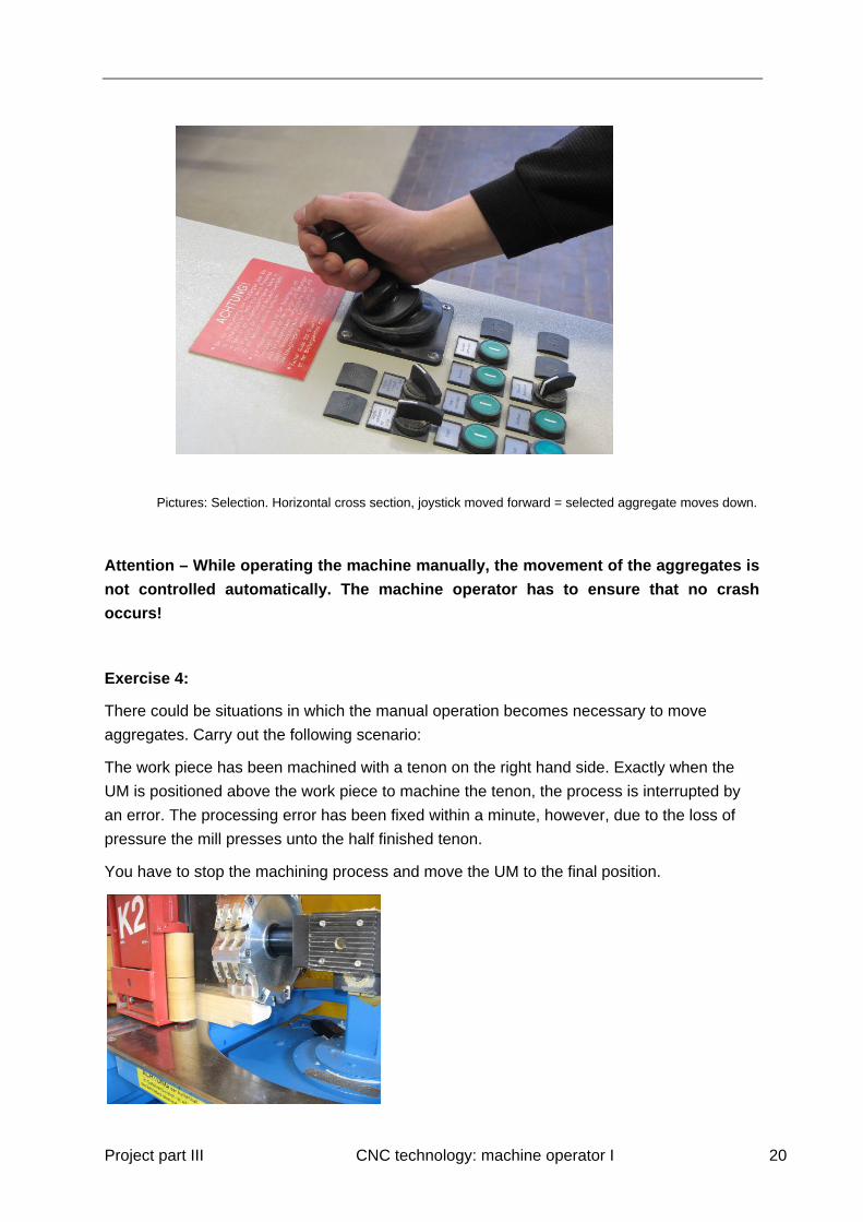
Pictures: Selection. Horizontal cross section, joystick moved forward = selected aggregate moves down.
Attention – While operating the machine manually, the movement of the aggregates is
not controlled automatically. The machine operator has to ensure that no crash
occurs!
Exercise 4:
There could be situations in which the manual operation becomes necessary to move
aggregates. Carry out the following scenario:
The work piece has been machined with a tenon on the right hand side. Exactly when the
UM is positioned above the work piece to machine the tenon, the process is interrupted by
an error. The processing error has been fixed within a minute, however, due to the loss of
pressure the mill presses unto the half finished tenon.
You have to stop the machining process and move the UM to the final position.

Project part III CNC technology: machine operator I 21
Picture: Situation during the interruption of the machining process
Picture: The aggregate is being moved
Picture: Aggregate in final position
5.2 Machine Data:
Every machine has its own set of machine specific data which includes information about the
available aggregates and tools. As every machine has a different configuration, the machine
data cannot be exchanged.
Every operator who prepares the production process must have a set of machine data in
order to properly plan the production steps. Machine data should always be kept up-to-date
as it is important for adjustments or maintenance work where the data may be required.
Therefore, it is important that the data can be saved to a drive and stored on a PC or
operator console.
In contrast to “Saving to the Operator Console” the function “Data transfer from an outside
source to the Operator Console” should be a rare exception. This should only be done after
connecting with the Hundegger Hotline as the result of this action is that the position of every
aggregate has to be checked.

Project part III CNC technology: machine operator I 22
5.3 Create and Maintain an Operator Profile:
All machine operators can be set up with an individual number and the operator signs on
with his/her number and signs off with the number “0”. Numbers can also be assigned for
tool changes and maintenance work which allows for reporting and analysis of run time and
efficiency. The data can be stored separately and analysed. Therefore, it is important for
machine operators to sign on/off correctly. To select the function “Usage Data” on the
operator console, the configuration for data transfer COM1 needs to be switched off.
Picture: Machine - Machine Data – Configuration
Exercise 5:
Every participant signs on to the system. For machine maintenance use the number “100”.
Throughout the course, all participants use the assigned number to sign on/off. At the end of
the course the collected data will be analysed and provides insight into the data collection.
Project part III CNC technology: machine operator I 23
5.4 Create a job and list the components:
A job is usually created in a CAD/CAM program and then transferred into the SPCP.
The alternative is to create the job with its individual processes in the SPCP. This requires
that all process data has to be programmed individually e.g. saw cuts, measurements,
tenons. Both methods achieve the same result, however, for a complex job the manual
programming of the machine requires more effort.
Create a job and name it “Joints” and assign the number “10000”:
Main menu Job New Job
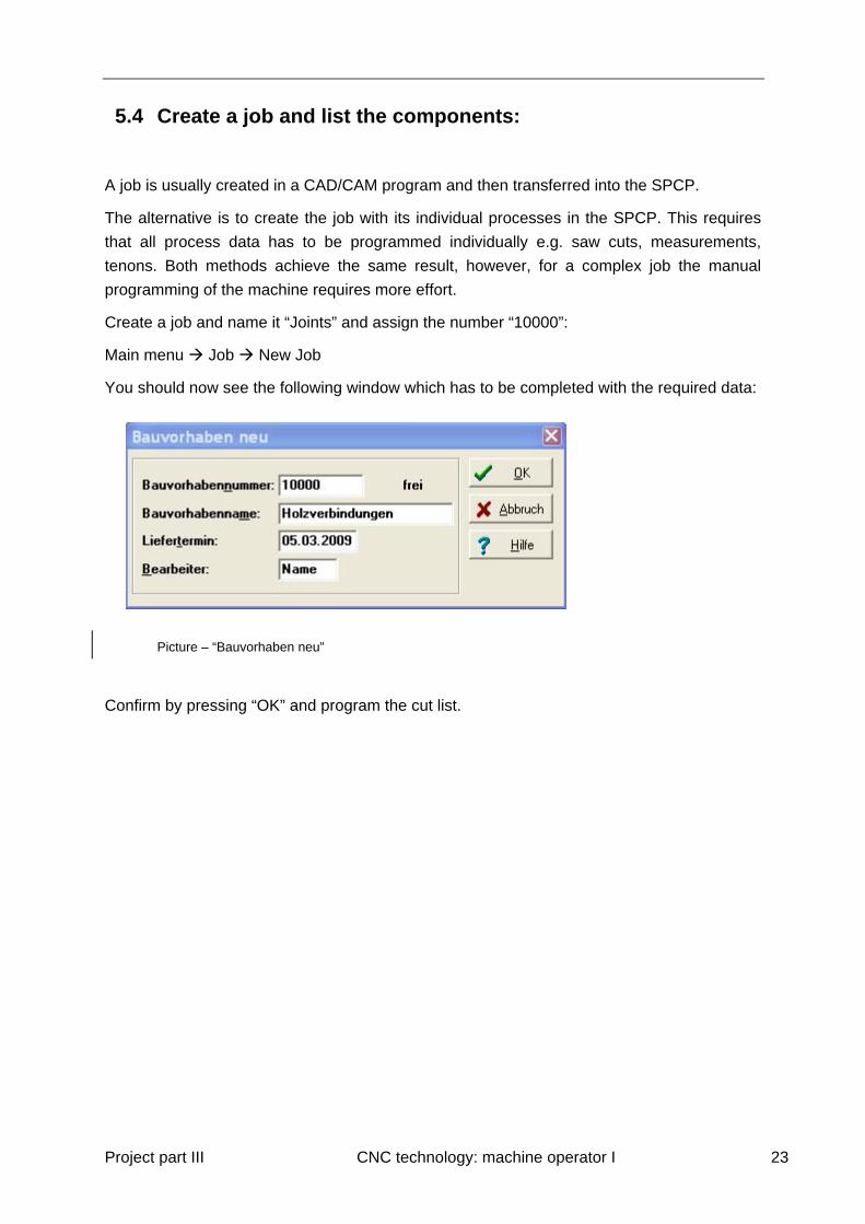
You should now see the following window which has to be completed with the required data:
Picture – “Bauvorhaben neu”
Confirm by pressing “OK” and program the cut list.
Project part III CNC technology: machine operator I 24
Add a workpiece and name it “Column”.
Picture - Column
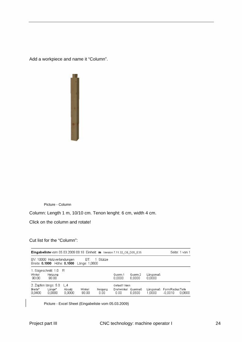
Column: Length 1 m, 10/10 cm. Tenon lenght: 6 cm, width 4 cm.
Click on the column and rotate!
Cut list for the “Column”:
Picture - Excel Sheet (Eingabeliste vom 05.03.2009)
Project part III CNC technology: machine operator I 25
Picture - Video outlining the cut list for the column
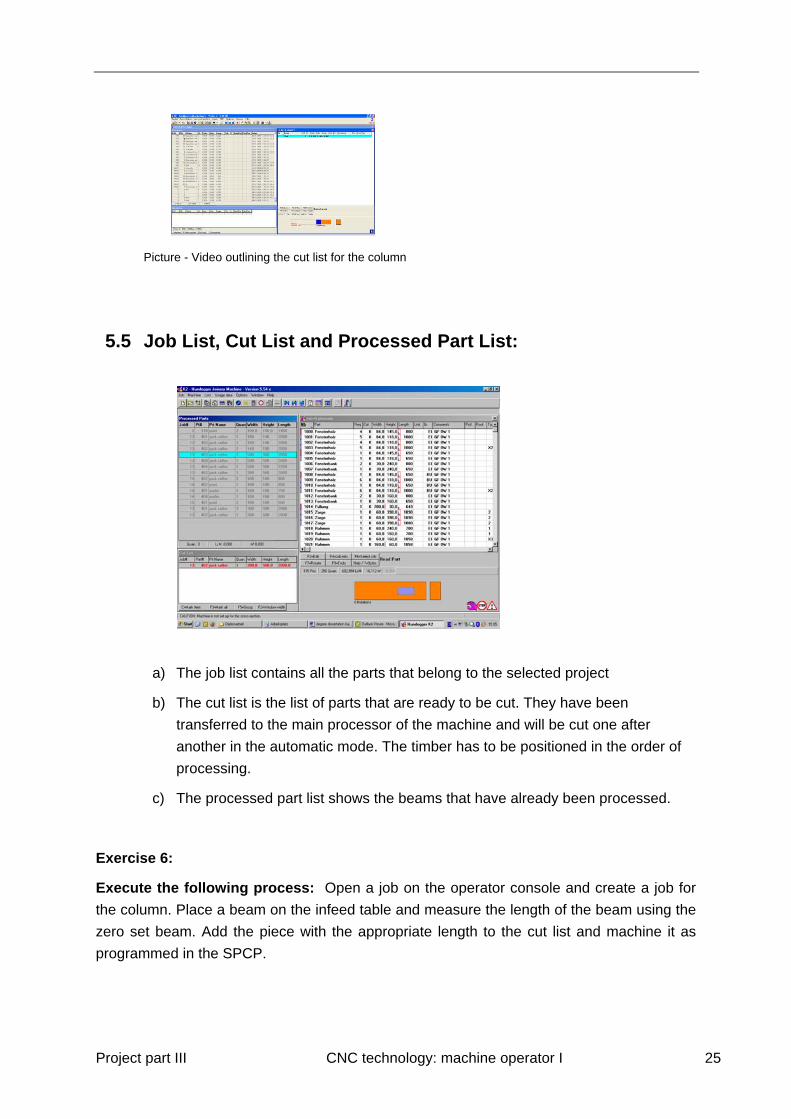
5.5 Job List, Cut List and Processed Part List:
a) The job list contains all the parts that belong to the selected project
b) The cut list is the list of parts that are ready to be cut. They have been
transferred to the main processor of the machine and will be cut one after
another in the automatic mode. The timber has to be positioned in the order of
processing.
c) The processed part list shows the beams that have already been processed.
Exercise 6:
Execute the following process: Open a job on the operator console and create a job for
the column. Place a beam on the infeed table and measure the length of the beam using the
zero set beam. Add the piece with the appropriate length to the cut list and machine it as
programmed in the SPCP.

Project part III CNC technology: machine operator I 26
Picture: Bauteil 1 “Stütze” übertragen
Test the modifying function for the cross section.
Is it possible to produce the work piece from a 12/12 cm beam? Which deviation in cross
section makes the correction in this field necessary?
(NOTE: You can adjust the beam cross section when you transfer the beam from the parts
list to the cut list. During the transfer options you are asked for the length of the beam and
the number of times you want to cut it. If you hit “F5” while in the window the dimension
offsets become available. But careful, this will only adjust the depth of cuts for sure, the
location should be adjusted also, but that means a mortise that was supposed to be 5 cm
deep will be deeper or more shallow [when offset is negative] and the other part may not fit.
This option doesn’t really “scale” everything.)
Project part III CNC technology: machine operator I 27
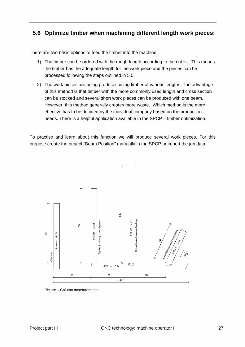
5.6 Optimize timber when machining different length work pieces:
There are two basic options to feed the timber into the machine:
1) The timber can be ordered with the rough length according to the cut list. This means
the timber has the adequate length for the work piece and the pieces can be
processed following the steps outlined in 5.5.
2) The work pieces are being produces using timber of various lengths. The advantage
of this method is that timber with the more commonly used length and cross section
can be stocked and several short work pieces can be produced with one beam.
However, this method generally creates more waste. Which method is the more
effective has to be decided by the individual company based on the production
needs. There is a helpful application available in the SPCP – timber optimization.
To practise and learn about this function we will produce several work pieces. For this
purpose create the project “Beam Position” manually in the SPCP or import the job data.
Picture – Column measurements

Project part III CNC technology: machine operator I 28
Picture – Columns (3D)
Video – How to import a job
6 Tool Changes and Adjustments:
It is necessary to keep the machine data up to date to prevent the tools from being damaged
and to achieve proper processing.
Press “D” and select “tools” in the left part of the machine data window to enter the tool data
window. Modifications as to which tools are loaded as well as modifications to individual tool
configurations (i.e. diameter, length and width of tools such as drills, mill heads, etc.) can be
made here.
The tool positions are shown in the first column.
· UM: Universal mill
· DT: Dovetail cutter
· EM: End mill
· V1 – V4: Tool positions for vertically actuated tools
· H1 – H4: Tool positions for horizontally actuated tools
Swap the tool in the marked position: Hold the '.' button and use the '+' and '-' keys to
scroll through the tools that have been defined for this position.
Project part III CNC technology: machine operator I 29
To edit the individual tool configurations highlight a tool and press “Enter”. Here you can
edit the tool configuration by highlighting it and pressing Enter or enter a new tool by
selecting “new/ empty” and pressing enter.
General remarks about tool change:
Gloves have to be used when working with sharp objects!
Keep the machine data up to date about removed/added tools
When tools are sharpened the geometry has to be revised in the machine data.
Make sure that all screws and chucks are screwed tightly before operating them.
Lose tools and machine parts can become fatal projectiles.
Do not forget to remove the wooden block that is used to block the UM when working
on the EM, dovetail cutter or UM.
Test the tools in the manual mode before using it for cutting timbers automatically!
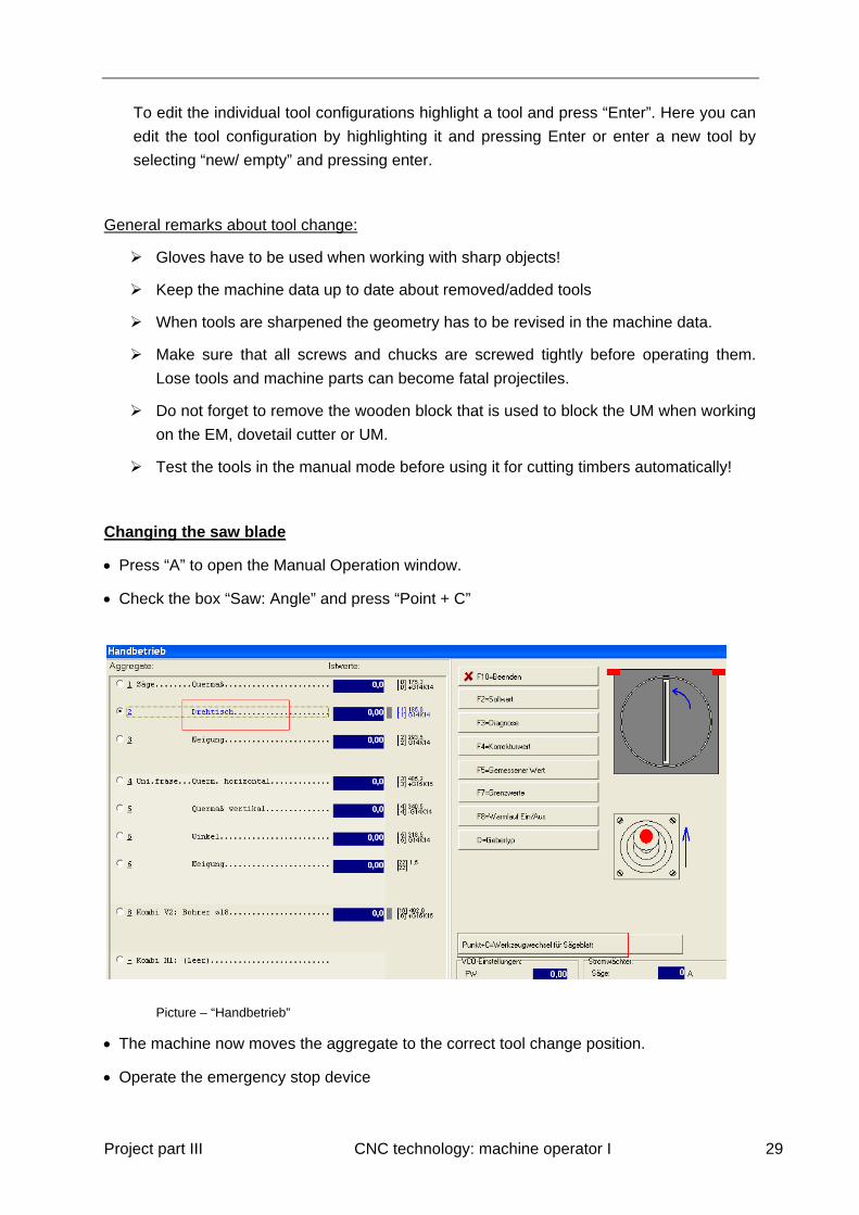
Changing the saw blade
Press “A” to open the Manual Operation window.
Check the box “Saw: Angle” and press “Point + C”
Picture – “Handbetrieb”
The machine now moves the aggregate to the correct tool change position.
Operate the emergency stop device

Project part III CNC technology: machine operator I 30
Switch off main isolation switch and lock
Switch off motor protection switch Q1.
Picture – Switch Q1
Disassemble saw blade protection, unscrew 4 screws and remove protection.
Picture – Protection is being removed
Undo nut (size 46) with the open ended spanner clockwise (left hand thread).

Project part III CNC technology: machine operator I 31
Lift off saw blade, and remove.
Clean flange and motor shaft – check for any dirt or small wooden pieces as those could
cause error messages and prohibit proper running of the equipment.
Pictures – Removal of the saw blade and visual check
Insert new blade from below and place on motor shaft (blade must lie flat against the
flange). Note: Is the new saw blade a different size the machine data has to be updated
with the new measurements.
Note direction of rotation and pin position (keying)
Put on fixing flange and tighten nut counter clockwise
Re-fit saw blade protection
Project part III CNC technology: machine operator I 32
Remove rotation protection!!!
Switch on the motor protection switch and the main isolation
Listen carefully during first operation after the change to detect any anomalies!
This workshop does not cover all the different steps of adjustment for each tool. Refer to the
manual to learn more about the adjustment of tools.
When you have to process a beam to check the adjustment of tools, always use a beam with
a perfectly rectangular section and with the correct dimension!
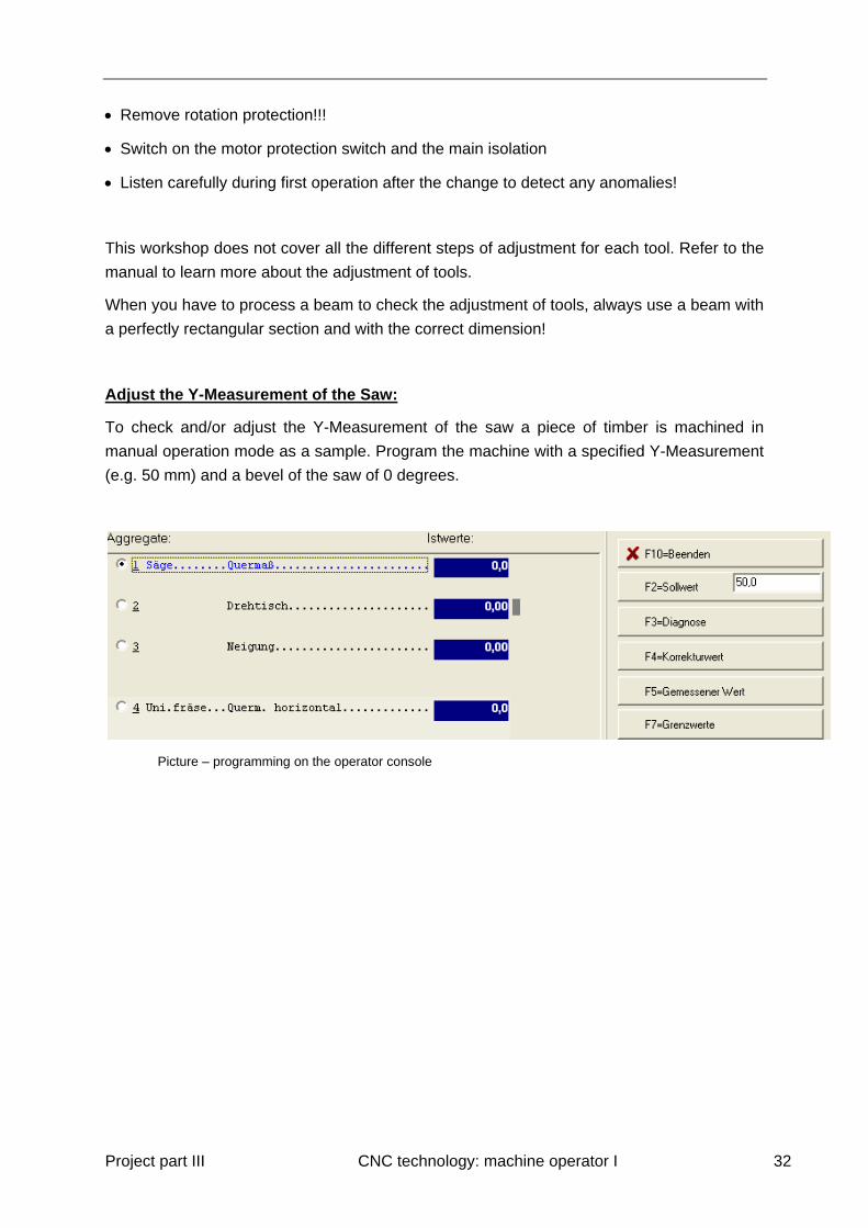
Adjust the Y-Measurement of the Saw:
To check and/or adjust the Y-Measurement of the saw a piece of timber is machined in
manual operation mode as a sample. Program the machine with a specified Y-Measurement
(e.g. 50 mm) and a bevel of the saw of 0 degrees.
Picture – programming on the operator console
Project part III CNC technology: machine operator I 33
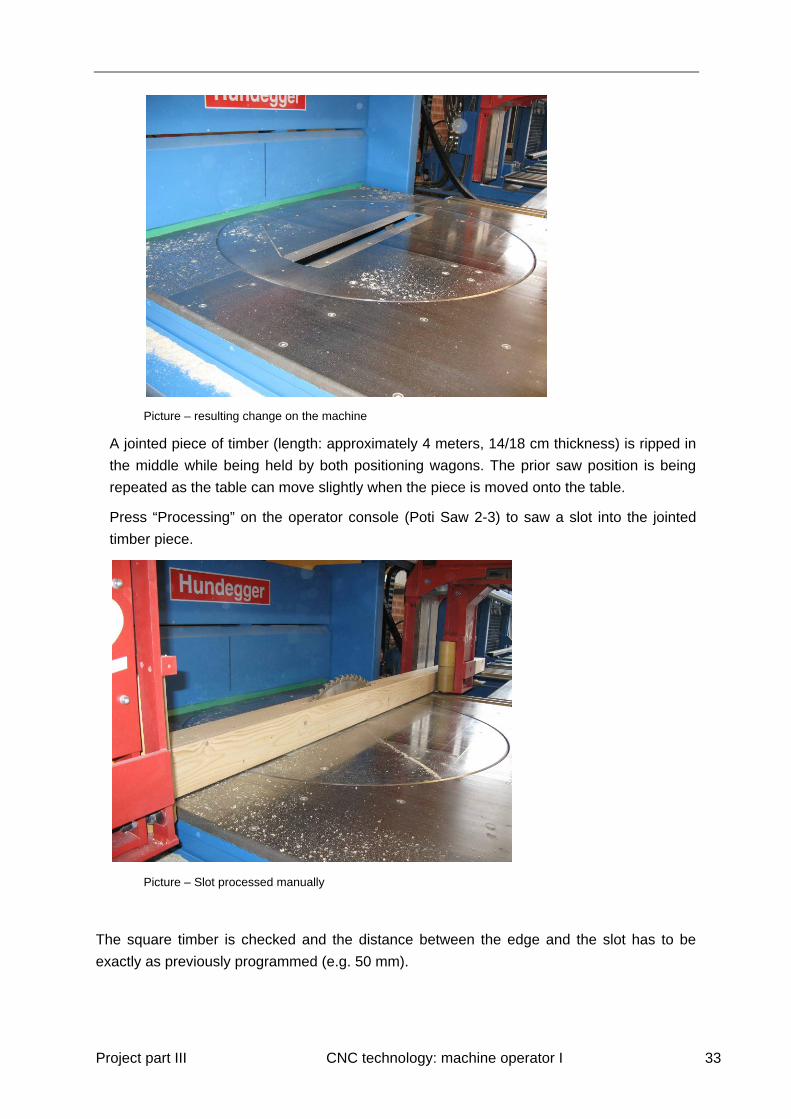
Picture – resulting change on the machine
A jointed piece of timber (length: approximately 4 meters, 14/18 cm thickness) is ripped in
the middle while being held by both positioning wagons. The prior saw position is being
repeated as the table can move slightly when the piece is moved onto the table.
Press “Processing” on the operator console (Poti Saw 2-3) to saw a slot into the jointed
timber piece.
Picture – Slot processed manually
The square timber is checked and the distance between the edge and the slot has to be
exactly as previously programmed (e.g. 50 mm).
Project part III CNC technology: machine operator I 34
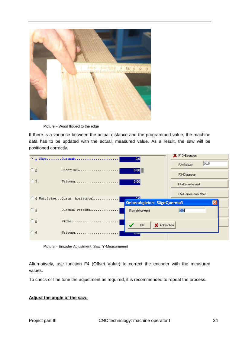
Picture – Wood flipped to the edge
If there is a variance between the actual distance and the programmed value, the machine
data has to be updated with the actual, measured value. As a result, the saw will be
positioned correctly.
Picture – Encoder Adjustment: Saw, Y-Measurement
Alternatively, use function F4 (Offset Value) to correct the encoder with the measured
values.
To check or fine tune the adjustment as required, it is recommended to repeat the process.
Adjust the angle of the saw:

Project part III CNC technology: machine operator I 35
To adjust the angle of the saw compare the measured angle with the angle shown on the
system.
Open the manual operation window and rotate the turntable counter-clockwise until it stops.
The chain that supports the angle movement of the saw may be stretched slightly and can
be loosened to lessen the tension.
Picture – Right hand pushes the release button, left hand moves the saw left and again right
Open the door of the saw, push the release button and move the turntable to the mechanical
stop manually. (The release button is located inside the saw box, on the top right hand
corner of the door frame).
Picture – Release button
Project part III CNC technology: machine operator I 36
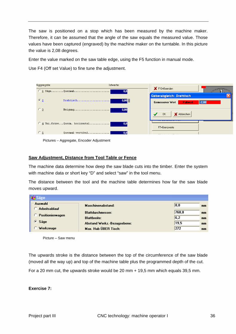
The saw is positioned on a stop which has been measured by the machine maker.
Therefore, it can be assumed that the angle of the saw equals the measured value. Those
values have been captured (engraved) by the machine maker on the turntable. In this picture
the value is 2,08 degrees.
Enter the value marked on the saw table edge, using the F5 function in manual mode.
Use F4 (Off set Value) to fine tune the adjustment.
Pictures – Aggregate, Encoder Adjustment
Saw Adjustment, Distance from Tool Table or Fence
The machine data determine how deep the saw blade cuts into the timber. Enter the system
with machine data or short key “D” and select “saw” in the tool menu.
The distance between the tool and the machine table determines how far the saw blade
moves upward.
Picture – Saw menu
The upwards stroke is the distance between the top of the circumference of the saw blade
(moved all the way up) and top of the machine table plus the programmed depth of the cut.
For a 20 mm cut, the upwards stroke would be 20 mm + 19,5 mm which equals 39,5 mm.
Exercise 7:
Project part III CNC technology: machine operator I 37
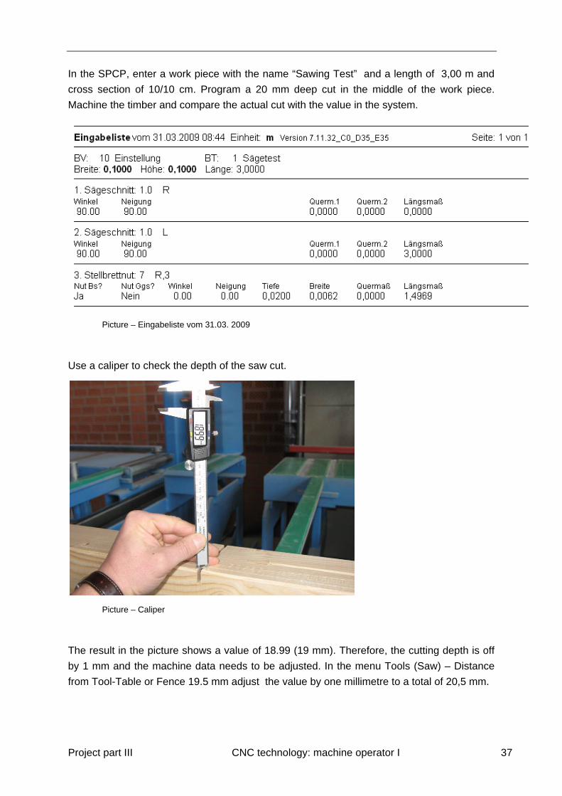
In the SPCP, enter a work piece with the name “Sawing Test” and a length of 3,00 m and
cross section of 10/10 cm. Program a 20 mm deep cut in the middle of the work piece.
Machine the timber and compare the actual cut with the value in the system.
Picture – Eingabeliste vom 31.03. 2009
Use a caliper to check the depth of the saw cut.
Picture – Caliper
The result in the picture shows a value of 18.99 (19 mm). Therefore, the cutting depth is off
by 1 mm and the machine data needs to be adjusted. In the menu Tools (Saw) – Distance
from Tool-Table or Fence 19.5 mm adjust the value by one millimetre to a total of 20,5 mm.
Project part III CNC technology: machine operator I 38
After the adjustment, the saw blade will be raised to 20,5 mm from the top of the machine
table and cuts 20 mm into the timber, which brings the total distance to 20,5 mm + 20 mm =
40,5 mm and the depth of the cut is now the desired value.
Repeat the machining process to check the result.
Adjust the bevel of the saw:
To recalibrate the position of the bevel of the saw blade, move the blade manually to the
stop position. The system should show 0 degrees. The machine manufacturer has created
this fixed position which can be used to check to correct setting of the blade. It is
recommended to check the value on a regular basis.
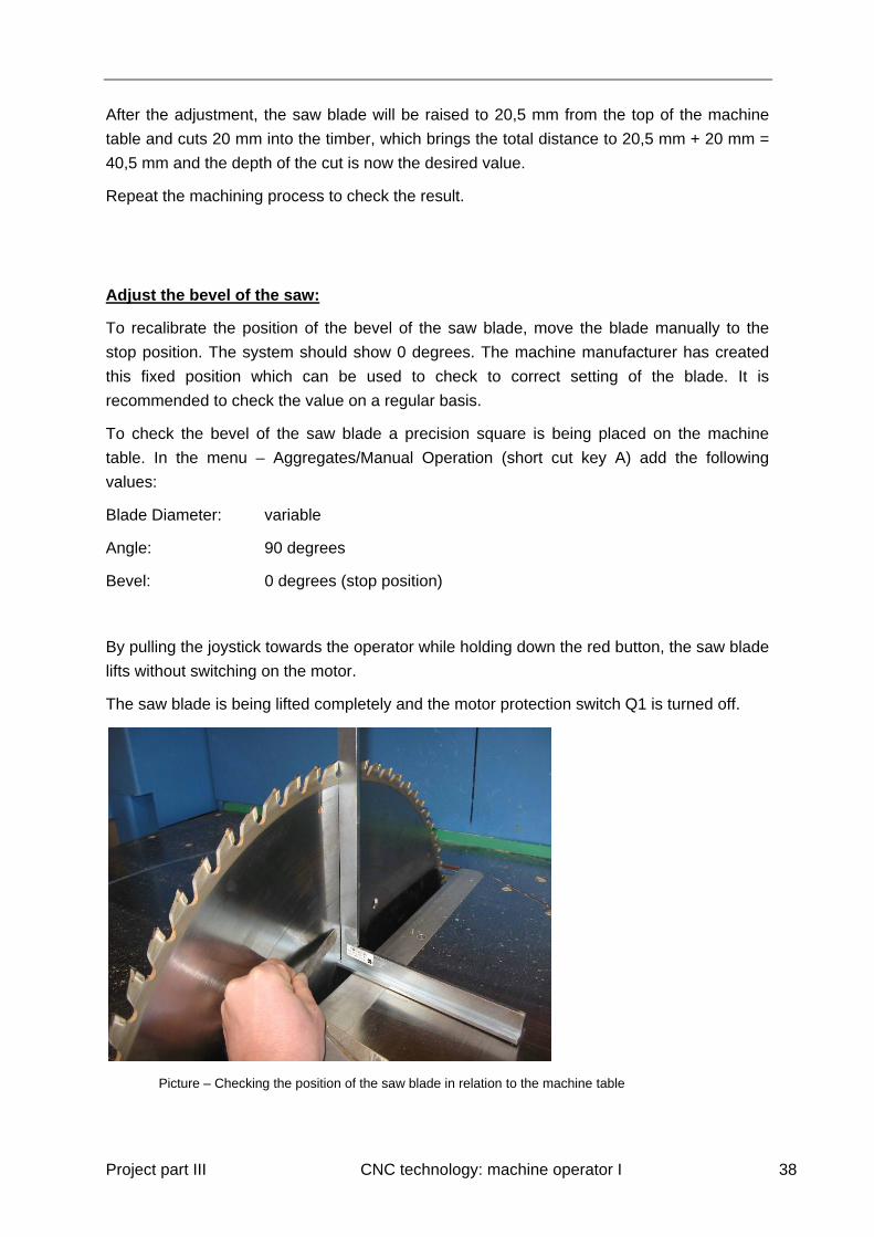
To check the bevel of the saw blade a precision square is being placed on the machine
table. In the menu – Aggregates/Manual Operation (short cut key A) add the following
values:
Blade Diameter: variable
Angle: 90 degrees
Bevel: 0 degrees (stop position)
By pulling the joystick towards the operator while holding down the red button, the saw blade
lifts without switching on the motor.
The saw blade is being lifted completely and the motor protection switch Q1 is turned off.
Picture – Checking the position of the saw blade in relation to the machine table
Project part III CNC technology: machine operator I 39
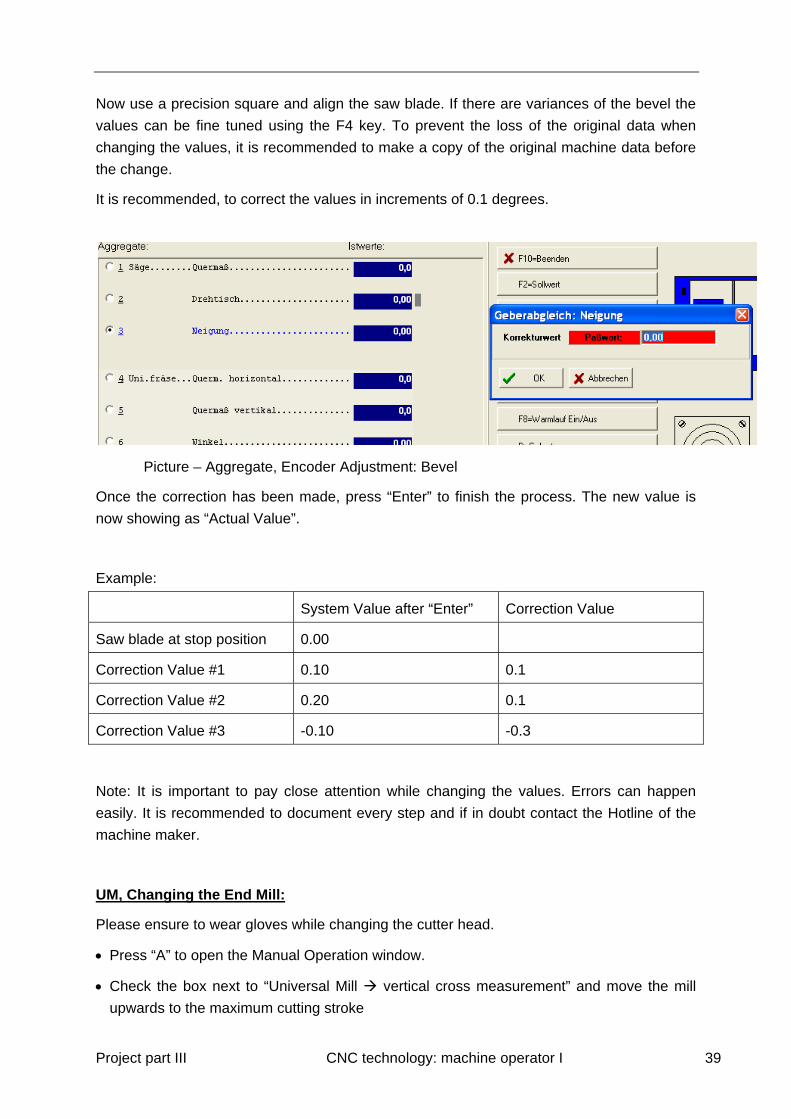
Now use a precision square and align the saw blade. If there are variances of the bevel the
values can be fine tuned using the F4 key. To prevent the loss of the original data when
changing the values, it is recommended to make a copy of the original machine data before
the change.
It is recommended, to correct the values in increments of 0.1 degrees.
Picture – Aggregate, Encoder Adjustment: Bevel
Once the correction has been made, press “Enter” to finish the process. The new value is
now showing as “Actual Value”.
Example:
System Value after “Enter” Correction Value
Saw blade at stop position 0.00
Correction Value #1 0.10 0.1
Correction Value #2 0.20 0.1
Correction Value #3 -0.10 -0.3
Note: It is important to pay close attention while changing the values. Errors can happen
easily. It is recommended to document every step and if in doubt contact the Hotline of the
machine maker.
UM, Changing the End Mill:
Please ensure to wear gloves while changing the cutter head.
Press “A” to open the Manual Operation window.
Check the box next to “Universal Mill vertical cross measurement” and move the mill
upwards to the maximum cutting stroke

Project part III CNC technology: machine operator I 40
Approach the optimum position with the F2 positioning function: “cross measurement:
500”, “Angle: 0°”
Picture – optimum position of the mill
Press the emergency stop button
Switch off main isolations switch and lock
Switch off motor protection switch Q2.
Push a suitable wooden piece (approx. 280 mm long) between the universal mill and the
box
Unscrew the clamping nut with the special spanner supplied by the machine manufacturer
Picture – unscrew the 20 mm end mill

Project part III CNC technology: machine operator I 41
The unit is removed carefully and if required, sharpened or measured. The box needs to
cleaned with a vacuum cleaner.
Picture – Tool has been removed, collet and nut are on top of the mill
When inserting the mill make sure that the shoulder on the mill shaft fits exactly into the
clamping sleeve
Tighten the clamping nut, turning against the direction of cutting
Picture – tighten carefully
Remove the wooden piece and check that all tools have been removed
Switch on the motor protection switch Q1 and the main switch
Test the mill in manual mode

Project part III CNC technology: machine operator I 42
If the tool geometry has changed you have to enter the new values in the machine data.
Use the short cut key D (Machine data) and select End Mill in the Tool menu.
Picture – Auswahlfenster
Press “Enter” to select the sub menu which allows the operator to select or create tools.
Picture – Werkzeuge auswählen für FF
Select the appropriate mill and check the existing settings. The diameter could have
decreased as a result of sharpening the tool. The new value needs to be entered in the field
“diameter”. The machine will calculate that for a mortise (width 40 mm) and a mill diameter of
38.7 mm the process will require two steps. The cutting edge may change as well and
should be corrected if the change can be measured.
One of the most important changes is the adjustment of the tip of the End Mill. It is measured
as the distance between the centre point (axis) of the support and the tip of the end mill. In
order to drill with the exact depth, the machine has to know the position. To check the value,
a sample piece is being processed.
Project part III CNC technology: machine operator I 43
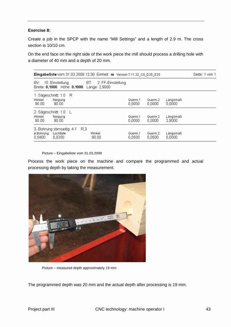
Exercise 8:
Create a job in the SPCP with the name “Mill Settings” and a length of 2.9 m. The cross
section is 10/10 cm.
On the end face on the right side of the work piece the mill should process a drilling hole with
a diameter of 40 mm and a depth of 20 mm.
Picture – Eingabeliste vom 31.03.2009
Process the work piece on the machine and compare the programmed and actual
processing depth by taking the measurement.
Picture – measured depth approximately 19 mm
The programmed depth was 20 mm and the actual depth after processing is 19 mm.

Project part III CNC technology: machine operator I 44
Therefore, the tip of the end mill needs to be adjusted. In this case the tool remains as is and
the adjustment is made in the machine data.
Open the menu Machine Data and move the cursor to the tip of the end mill.
Picture – Werkzeuge auswählen for FF
The value in this example is 330.1 mm. The result of the sample process is off by one mm.
The processing steps are that the tool moves to the work piece and the processing is
executed at the programmed depth. Therefore, an additional step needs to be adjusted to
ensure the required depth is reached. Is the distance for the tip of the end mill reduced the
aggregate has to move further to process the work piece as programmed.
In our case:
Adjusting the end mill “front edge” to 329.1 mm (reduction by one 1mm)
The end mill moves now 1 mm further to the processing position (19 mm + 1 mm = 20 mm).
A further sample process has to be executed to double check the result.
The adjustment of the milling edge is quite exact, however, a coordination with the UM
should be done as a number of processes use several tools. If the coordination between the
tools is not precise, there could be small cutting marks that measures in the 10th millimetre
span, but are immediately visible.
A sample work piece is being processed in which both milling units are utilized. A good
sample is the hip rafter bird´s mouth. The piece must have a certain size otherwise the
machine will only use the end mill for processing.
Project part III CNC technology: machine operator I 45
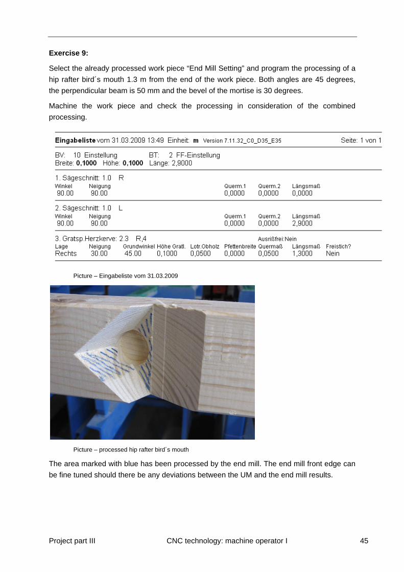
Exercise 9:
Select the already processed work piece “End Mill Setting” and program the processing of a
hip rafter bird´s mouth 1.3 m from the end of the work piece. Both angles are 45 degrees,
the perpendicular beam is 50 mm and the bevel of the mortise is 30 degrees.
Machine the work piece and check the processing in consideration of the combined
processing.
Picture – Eingabeliste vom 31.03.2009
Picture – processed hip rafter bird´s mouth
The area marked with blue has been processed by the end mill. The end mill front edge can
be fine tuned should there be any deviations between the UM and the end mill results.

Project part III CNC technology: machine operator I 46
Adjust the angle of the UM:
The adjustment of the angle of the universal mill is achieved in several easy steps.
In the manual mode, move the UM counter-clockwise to the stop position. Using the F5 key,
enter the value that is engraved next to the mill unit tower.
Picture –UM in stop position, the pencil points towards the value
Picture – Value: -2.04 degrees

Project part III CNC technology: machine operator I 47
Picture – Screenshot, Encoder Adjustment: Angle
Using the F5 key, enter the value that was measured (-2.04 degrees). Now the measured
value matches the value in the machine setting. If a fine tuning is necessary, use F4 to
correct the value.
Adjust the bevel of the UM (5-axis only):
The adjustment of the bevel of the UM is made by processing a sample work piece. For this
purpose a machining process has to be selected that will show any deviation of the bevel
from the horizontal position can be measured easily.
Picture – Bevel UM = Deviation from the horizontal position
Project part III CNC technology: machine operator I 48
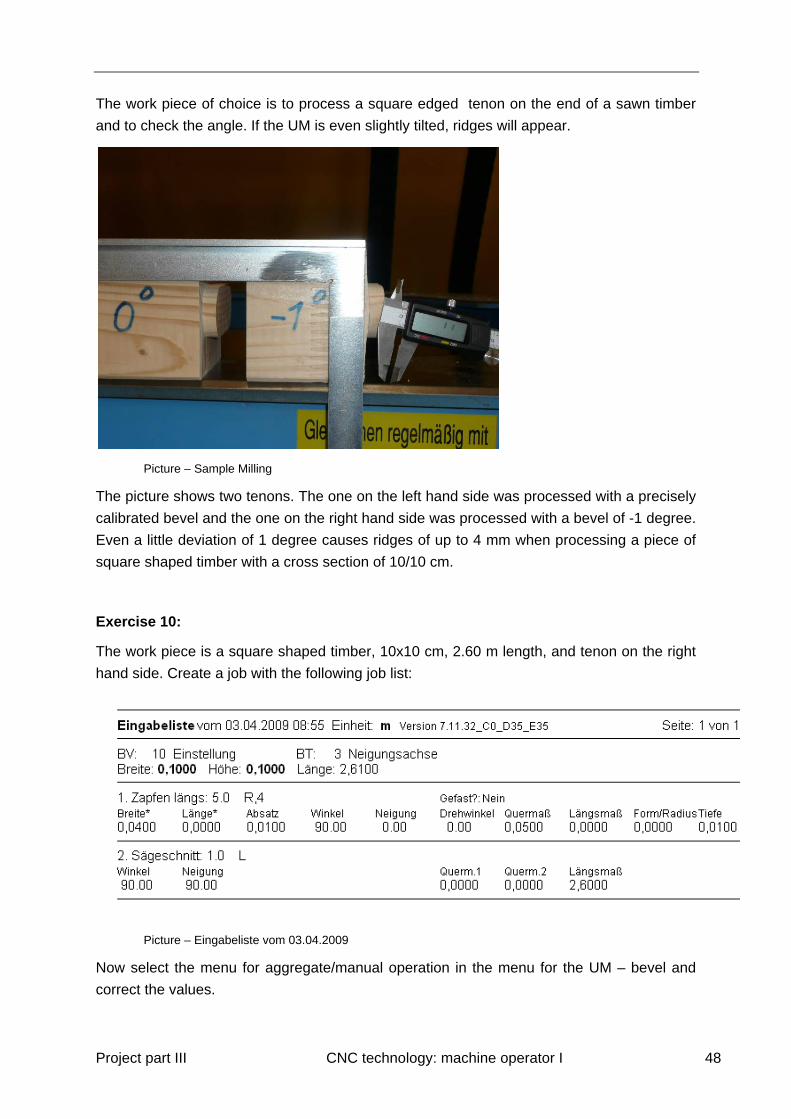
The work piece of choice is to process a square edged tenon on the end of a sawn timber
and to check the angle. If the UM is even slightly tilted, ridges will appear.
Picture – Sample Milling
The picture shows two tenons. The one on the left hand side was processed with a precisely
calibrated bevel and the one on the right hand side was processed with a bevel of -1 degree.
Even a little deviation of 1 degree causes ridges of up to 4 mm when processing a piece of
square shaped timber with a cross section of 10/10 cm.
Exercise 10:
The work piece is a square shaped timber, 10x10 cm, 2.60 m length, and tenon on the right
hand side. Create a job with the following job list:
Picture – Eingabeliste vom 03.04.2009
Now select the menu for aggregate/manual operation in the menu for the UM – bevel and
correct the values.
Project part III CNC technology: machine operator I 49
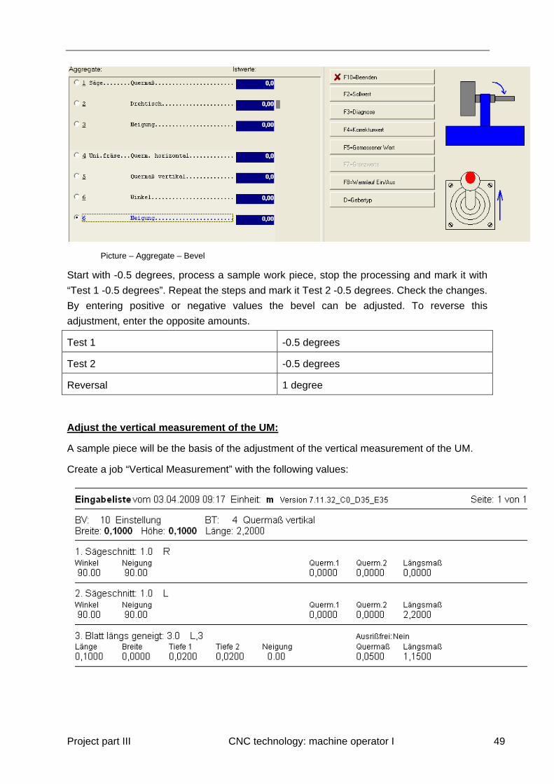
Picture – Aggregate – Bevel
Start with -0.5 degrees, process a sample work piece, stop the processing and mark it with
“Test 1 -0.5 degrees”. Repeat the steps and mark it Test 2 -0.5 degrees. Check the changes.
By entering positive or negative values the bevel can be adjusted. To reverse this
adjustment, enter the opposite amounts.
Test 1 -0.5 degrees
Test 2 -0.5 degrees
Reversal 1 degree
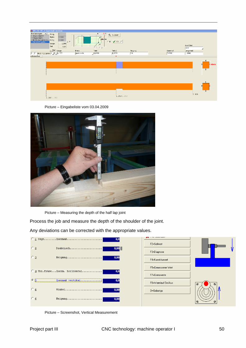
Adjust the vertical measurement of the UM:
A sample piece will be the basis of the adjustment of the vertical measurement of the UM.
Create a job “Vertical Measurement” with the following values:
Project part III CNC technology: machine operator I 50
Picture – Eingabeliste vom 03.04.2009
Picture – Measuring the depth of the half lap joint
Process the job and measure the depth of the shoulder of the joint.
Any deviations can be corrected with the appropriate values.
Picture – Screenshot, Vertical Measurement
Project part III CNC technology: machine operator I 51
The changes do not affect the pieces that are in the job list. The work piece is machined
again. Every adjustment of the values should be logged until the process has been
completed. This will enable the operator to reverse the changes if necessary.
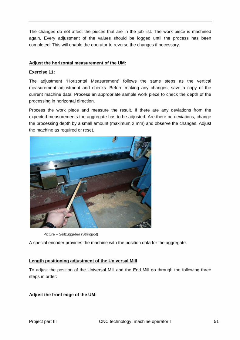
Adjust the horizontal measurement of the UM:
Exercise 11:
The adjustment “Horizontal Measurement” follows the same steps as the vertical
measurement adjustment and checks. Before making any changes, save a copy of the
current machine data. Process an appropriate sample work piece to check the depth of the
processing in horizontal direction.
Process the work piece and measure the result. If there are any deviations from the
expected measurements the aggregate has to be adjusted. Are there no deviations, change
the processing depth by a small amount (maximum 2 mm) and observe the changes. Adjust
the machine as required or reset.
Picture – Seilzuggeber (Stringpot)
A special encoder provides the machine with the position data for the aggregate.
Length positioning adjustment of the Universal Mill
To adjust the position of the Universal Mill and the End Mill go through the following three
steps in order:
Adjust the front edge of the UM:
Project part III CNC technology: machine operator I 52
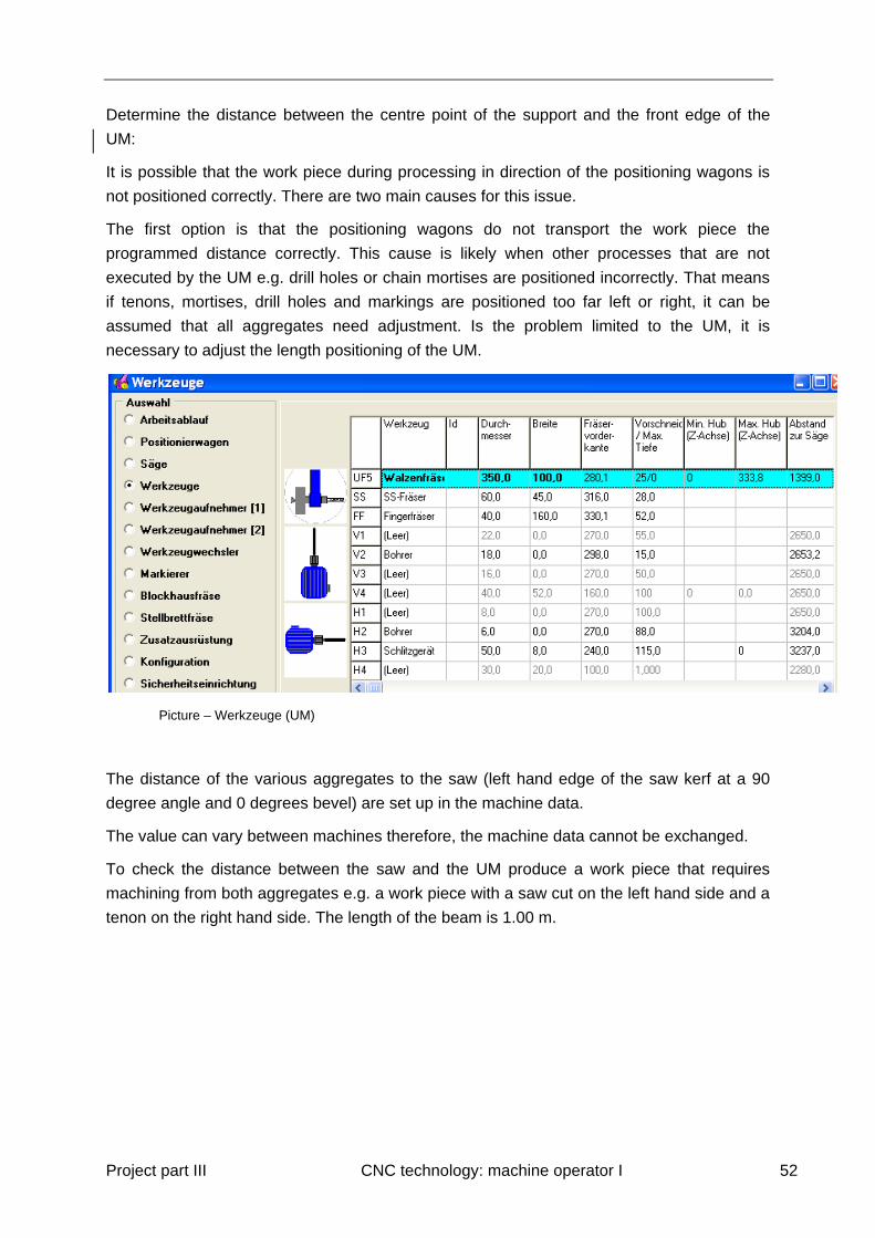
Determine the distance between the centre point of the support and the front edge of the
UM:
It is possible that the work piece during processing in direction of the positioning wagons is
not positioned correctly. There are two main causes for this issue.
The first option is that the positioning wagons do not transport the work piece the
programmed distance correctly. This cause is likely when other processes that are not
executed by the UM e.g. drill holes or chain mortises are positioned incorrectly. That means
if tenons, mortises, drill holes and markings are positioned too far left or right, it can be
assumed that all aggregates need adjustment. Is the problem limited to the UM, it is
necessary to adjust the length positioning of the UM.
Picture – Werkzeuge (UM)
The distance of the various aggregates to the saw (left hand edge of the saw kerf at a 90
degree angle and 0 degrees bevel) are set up in the machine data.
The value can vary between machines therefore, the machine data cannot be exchanged.
To check the distance between the saw and the UM produce a work piece that requires
machining from both aggregates e.g. a work piece with a saw cut on the left hand side and a
tenon on the right hand side. The length of the beam is 1.00 m.

Project part III CNC technology: machine operator I 53
Picture – Abstand UM
Picture – Eingabeliste vom 06.04.2009
Take the measurements of the processed work piece.
Picture – Measurement
The measured value is exactly 1.0 m and no adjustment is necessary. Should the measured
value be greater than the programmed target value, the distance between the saw and UM
in the machine data has to be reduced by the value of the deviation and vice versa. The
machine requires the data for the correct transport of the work piece.
Project part III CNC technology: machine operator I 54
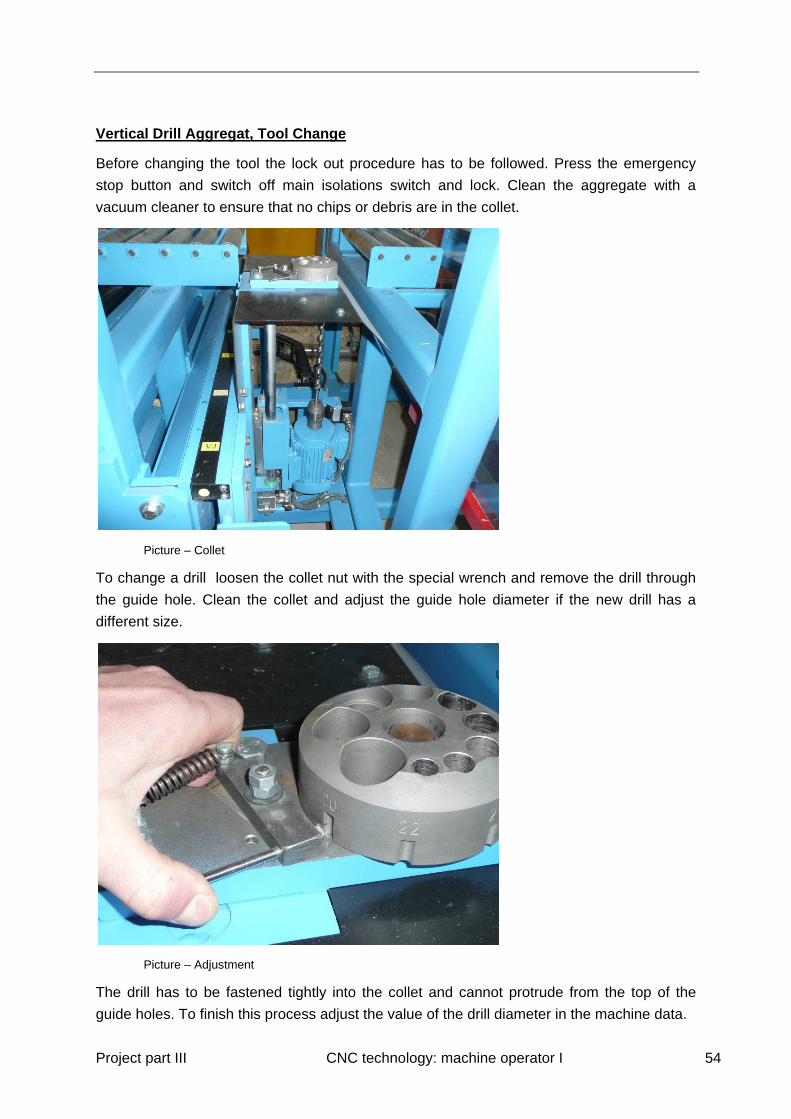
Vertical Drill Aggregat, Tool Change
Before changing the tool the lock out procedure has to be followed. Press the emergency
stop button and switch off main isolations switch and lock. Clean the aggregate with a
vacuum cleaner to ensure that no chips or debris are in the collet.
Picture – Collet
To change a drill loosen the collet nut with the special wrench and remove the drill through
the guide hole. Clean the collet and adjust the guide hole diameter if the new drill has a
different size.
Picture – Adjustment
The drill has to be fastened tightly into the collet and cannot protrude from the top of the
guide holes. To finish this process adjust the value of the drill diameter in the machine data.
Project part III CNC technology: machine operator I 55
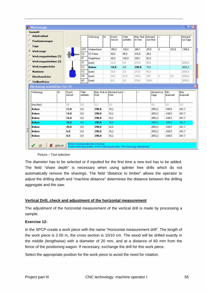
Picture – Tool selection
The diameter has to be selected or if inputted for the first time a new tool has to be added.
The field “share depth” is necessary when using splinter free drills which do not
automatically remove the shavings. The field “distance to timber” allows the operator to
adjust the drilling depth and “machine distance” determines the distance between the drilling
aggregate and the saw.
Vertical Drill, check and adjustment of the horizontal measurement
The adjustment of the horizontal measurement of the vertical drill is made by processing a
sample.
Exercise 12:
In the SPCP create a work piece with the name “Horizontal measurement drill”. The length of
the work piece is 2.00 m, the cross section is 10/10 cm. The wood will be drilled exactly in
the middle (lengthwise) with a diameter of 20 mm, and at a distance of 60 mm from the
fence of the positioning wagon. If necessary, exchange the drill for this work piece.
Select the appropriate position for the work piece to avoid the need for rotation.

Project part III CNC technology: machine operator I 56
Pictures – Screenshot from the SPCP (Fence of the positioning wagon)
and machine detail
Process the work piece as programmed in the SPCP and check the drilling. Use a calliper to
measure the distance from the fence of the positioning wagon to the edge of the drilling,
which should be 50 mm.
The programmed cross section is based on the centre of the drilling (50 mm + 20 mm/2 = 60
mm)

Project part III CNC technology: machine operator I 57
Picture – measured distance from the edge is 50.19 mm
The deviation is 0.19 mm. The operator has to determine if that is acceptable. A more
accurate result can be achieved by measuring where the drill enters the wood (from
underneath). In the picture above the measurement was taken from the top for more clarity.
In this case the measured cross section is 50.19 mm + 10 = 60.19 mm.
An adjustment can be made by selecting aggregates/manual operation from the menu and
using F4 (encoder adjustment). This change does not affect the work pieces in the cut list.
All beams that are added to the cut list after the change was made will be processed with the
new values.
Slot cutter, exchange the chain
Before changing the tool the lock out procedure has to be followed. Press the emergency
stop button and switch off main isolations switch and lock. Clean the aggregate with a
vacuum cleaner.
Project part III CNC technology: machine operator I 58
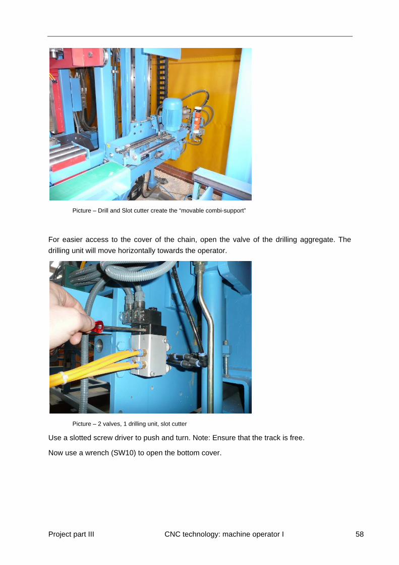
Picture – Drill and Slot cutter create the “movable combi-support”
For easier access to the cover of the chain, open the valve of the drilling aggregate. The
drilling unit will move horizontally towards the operator.
Picture – 2 valves, 1 drilling unit, slot cutter
Use a slotted screw driver to push and turn. Note: Ensure that the track is free.
Now use a wrench (SW10) to open the bottom cover.
Project part III CNC technology: machine operator I 59
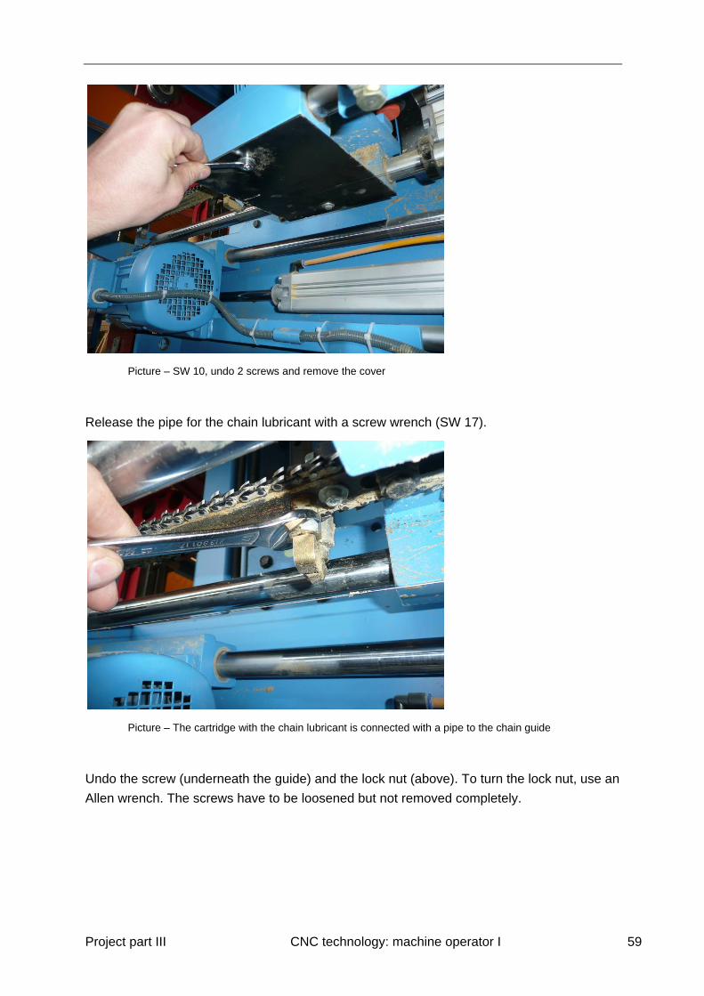
Picture – SW 10, undo 2 screws and remove the cover
Release the pipe for the chain lubricant with a screw wrench (SW 17).
Picture – The cartridge with the chain lubricant is connected with a pipe to the chain guide
Undo the screw (underneath the guide) and the lock nut (above). To turn the lock nut, use an
Allen wrench. The screws have to be loosened but not removed completely.
Project part III CNC technology: machine operator I 60
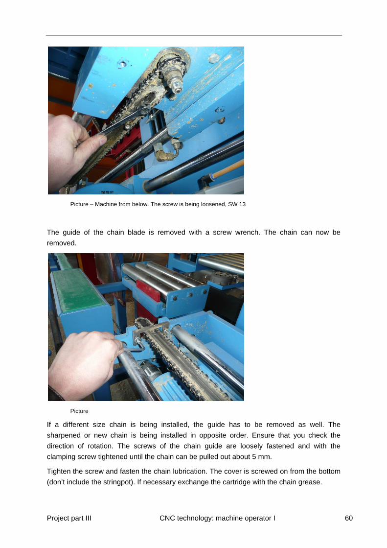
Picture – Machine from below. The screw is being loosened, SW 13
The guide of the chain blade is removed with a screw wrench. The chain can now be
removed.
Picture
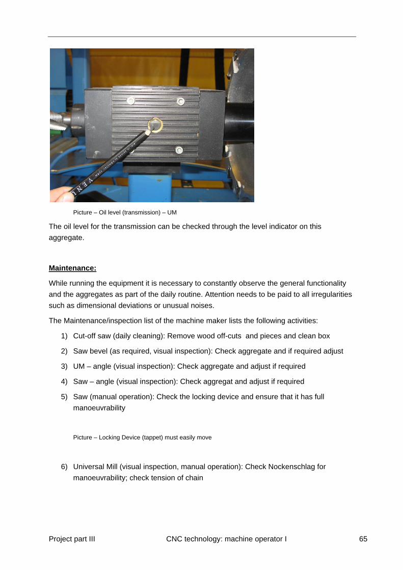
If a different size chain is being installed, the guide has to be removed as well. The
sharpened or new chain is being installed in opposite order. Ensure that you check the
direction of rotation. The screws of the chain guide are loosely fastened and with the
clamping screw tightened until the chain can be pulled out about 5 mm.
Tighten the screw and fasten the chain lubrication. The cover is screwed on from the bottom
(don’t include the stringpot). If necessary exchange the cartridge with the chain grease.

Project part III CNC technology: machine operator I 61
Picture – Exchange of the cartridge
Update the machine data, if a different slot cutter model has been installed.
Exercise 13:
The slot cutter unit contains an 8 mm cutter. After (supposedly) changing the unit you want
to update the machine data with a 12 mm unit. This size tool has not been installed before
and therefore, needs to be added.
Enter the menu machine data – tools – slot cutter. Select new and hit enter.
Select slot cutter. Please note that this is the only available selection, however, other
aggregate have more selection e.g. mill, drill. A copy of an existing tool is generated which
has to be adjusted with the current data.
Picture – select tool for H3

Project part III CNC technology: machine operator I 62
Generally, only the values for the width of the chain and the guide have to be changed,
however, the other entries have to be checked.
The tool may change as a result of sharpening and therefore, it should be measured or a
sample should be processed.
Exercise 14:
You have been presented with a variety of possibilities to adjust and fine tune tools and
aggregates. While running the production, you discover that the machining depth is not
correct. The slot cutter mills the recess 2 mm to deep.
Describe how to adjust the machine:
_________________________________________________________________________
_________________________________________________________________________
You notice that the position of the slots lengthswise are not correct. What are your next
steps?
_________________________________________________________________________
_________________________________________________________________________
6.1 Frequent Error Messages and Troubleshooting
The following icons may pop up in the bottom left corner of the screen when highlighting a
part in the job list:
This icon appears if a process cannot be carried out completely, e.g. the saw
cannot reach the designated end of a saw stroke. These processes will have to be
completed with hand tools
This icon shows up if the machine is not able to process the part, e.g. because the
timber is too big/ small to be processed. This part cannot be transferred to the
cutting list.

Project part III CNC technology: machine operator I 63
This icon warns you about safety issues. You are informed that you have to pay
special attention to certain processes.
This icon informs you that there are certain requirements for the member to be
processed, e.g. a longer piece of timber is required
The question mark indicates that a tool that the machine needs to machine a process
is not entered in the machine data. If you do not insert the correct tool the process is
ignored.
Some of the problems can be solved by rotating the timber in the SPCP, by installing or
uninstalling tools or by replacing processes that can’t be executed by the machine with other
processes. Please see some examples below:
Note: “No clamping points found near process” when processing a hip ridge cut
Proposed Solution: Process the hip ridge cut with the saw instead of the UM
Issue: Ejector is stopped by fragments of wood that are stuck in the slot of the saw.
Proposed Solution: Remove the fragments manually (follow all safety measures) and press
start.
Issue: “Disturbance at the Positioning Wagon”. The positioning wagon does not move when
the lever is pushed.
Proposed Solution: Restart the complete system. The PC of the machine console and the
PC in the main switchboard has to be restarted.
7 Machine Maintenance, Oils and Fluids
The machine requires a number of different oils, lubrication and fluids for the daily operation.
Ensure that all maintenance steps outlined in the user manual are followed and that only the
recommended materials are being used for proper operation of the machine. Regular
maintenance and exchange of fluids will support efficient production and reduce repair costs.
7.1 General Maintenance

Project part III CNC technology: machine operator I 64
Please refer to the manual for required maintenance schedules. All noted intervals are
meant as recommendations and the actual schedule depends on the general use of the
machine e.g. one or two shifts per day.
Before maintenance work commences, the working area has to be secured. Signs or
barriers can be helpful for this purpose. Ensure that all lock out procedures are carefully
followed. To clean the machine use compressed air or the suction system. Ensure that
hoses, wires and screws are not damaged in the cleaning process.
Finally, ensure that all parts that have been removed for the maintenance process are being
secured again, all connections are checked and tools are being removed from the machine.
Machine Check before Work Commences
Check the oil daily before the first shift starts.
Picture – Hydraulic aggregate: The oil level must be within the upper 30% mark.
If the oil level is below the top 30% mark it could indicate a leak which has to be repaired
immediately. Do not turn on the machine and call the service centre to discuss the
necessary repair.
Project part III CNC technology: machine operator I 65
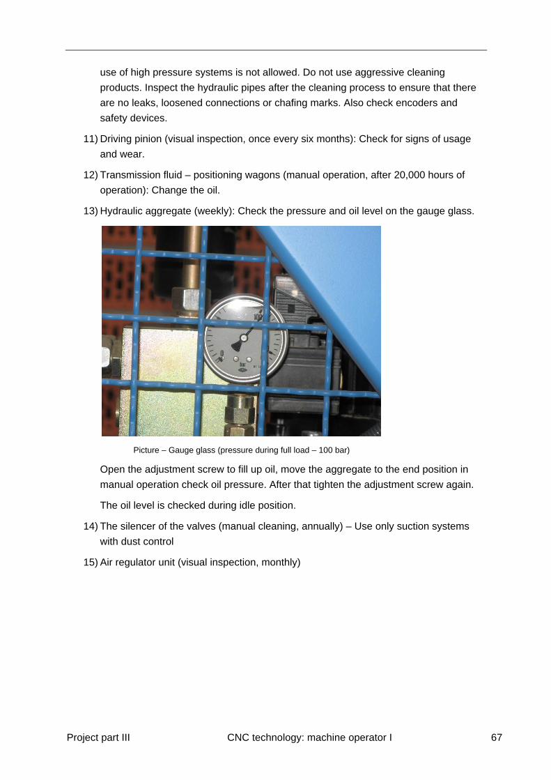
Picture – Oil level (transmission) – UM
The oil level for the transmission can be checked through the level indicator on this
aggregate.
Maintenance:
While running the equipment it is necessary to constantly observe the general functionality
and the aggregates as part of the daily routine. Attention needs to be paid to all irregularities
such as dimensional deviations or unusual noises.
The Maintenance/inspection list of the machine maker lists the following activities:
1) Cut-off saw (daily cleaning): Remove wood off-cuts and pieces and clean box
2) Saw bevel (as required, visual inspection): Check aggregate and if required adjust
3) UM – angle (visual inspection): Check aggregate and adjust if required
4) Saw – angle (visual inspection): Check aggregat and adjust if required
5) Saw (manual operation): Check the locking device and ensure that it has full
manoeuvrability
Picture – Locking Device (tappet) must easily move
6) Universal Mill (visual inspection, manual operation): Check Nockenschlag for
manoeuvrability; check tension of chain

Project part III CNC technology: machine operator I 66
7) Slot Cutter (as required, visual insp
ection, manual
operation): Check automatic use of lubricant – is the consumption reasonable?
8) Lubrication of machine table (lubricate regularly as required): Apply the
recommended lubricant to the sawing table, UM table and to the fence. The amount
of lubricant used depends on the use of the machine and can vary considerably.
9) Rolls of the positioning wagons (visual inspection, as required) – the rolls have to sit
tightly – if not adjustments need to be made.
Picture – Adjust the tightness of the rolls
10) Machine (manual operation, once a week or as required): Cleaning of the machine.
Use suction system with dust control. Cleaning with air pressure, water pressure and
Project part III CNC technology: machine operator I 67
use of high pressure systems is not allowed. Do not use aggressive cleaning
products. Inspect the hydraulic pipes after the cleaning process to ensure that there
are no leaks, loosened connections or chafing marks. Also check encoders and
safety devices.
11) Driving pinion (visual inspection, once every six months): Check for signs of usage
and wear.
12) Transmission fluid – positioning wagons (manual operation, after 20,000 hours of
operation): Change the oil.
13) Hydraulic aggregate (weekly): Check the pressure and oil level on the gauge glass.
Picture – Gauge glass (pressure during full load – 100 bar)
Open the adjustment screw to fill up oil, move the aggregate to the end position in
manual operation check oil pressure. After that tighten the adjustment screw again.
The oil level is checked during idle position.
14) The silencer of the valves (manual cleaning, annually) – Use only suction systems
with dust control
15) Air regulator unit (visual inspection, monthly)

Project part III CNC technology: machine operator I 68
Picture - unit with gauge
Newer machines may not need an oil unit. The adjustment screw should be opened
by about two turns, the consumption during operation should be approximately one
drop/3-4 seconds. For a one-shift operation one filling should last 3-4 months.
The minimum pressure is about 8.5 bar, the standard operation pressure ranges from
8.5 to 10 bar.
16) Lubricant (manual operation, monthly, more often as required): Apply lubricant to all
linear tracks for the saw, positioning wagons, rotator, UM etc.
Picture – Lubrication
The grease nipples are marked with yellow stickers. Ensure that the machine is clean
before applying the lubricant.
17) Maintenance Log

Project part III CNC technology: machine operator I 69
It is recommended to keep a maintenance log at the machine which is easily
accessible. This allows the operator to immediately track any irregularity and repairs
and the maintenance can be monitored. Therefore, it is important to assign areas of
responsibility around maintenance.
Picture – Betriebs- und Wartungsheft
8 Lists:
The machine allows the operator a flexible solution to create lists through the SPCP function.
Select Main menu – lists and the following lists are available:
- Parts list
- Sawmill list
- Saw milling list file
- Unit list
- Rough cut list
- Operating time each part
- Operation statistics
- Delivery slip
- Input list
- List of operations
- Machine data list

Project part III CNC technology: machine operator I 70
8.1 Lists and Layout
In the main menu select Options – Lists to set up initial settings.
Picture – “Allgemeines”
The menu item “Options” covers information for lengths, units and processing times. The
combination of cycle duration and potentiometer position UM determines the display of
processing times. This setting should be adjusted based on the company’s needs. To get
meaningful reporting, track the machining times during several projects and adjust the
values until the display reflects the times correctly.
Picture – Edit info
The picture above shows a machining time of 0.08 hours at a cycle duration of 5 and Poti 5.5
Picture – Edit info
The second picture shows a machining time of 0.06 hours and a cycle duration of 1 and Poti
10.
Those values are theoretical only, the potentiometer on the operator console alters
sometimes due to different processes and sharpening of tools. If the values are not adjusted
regularly, the machining times may become shorter or longer than the displayed times.
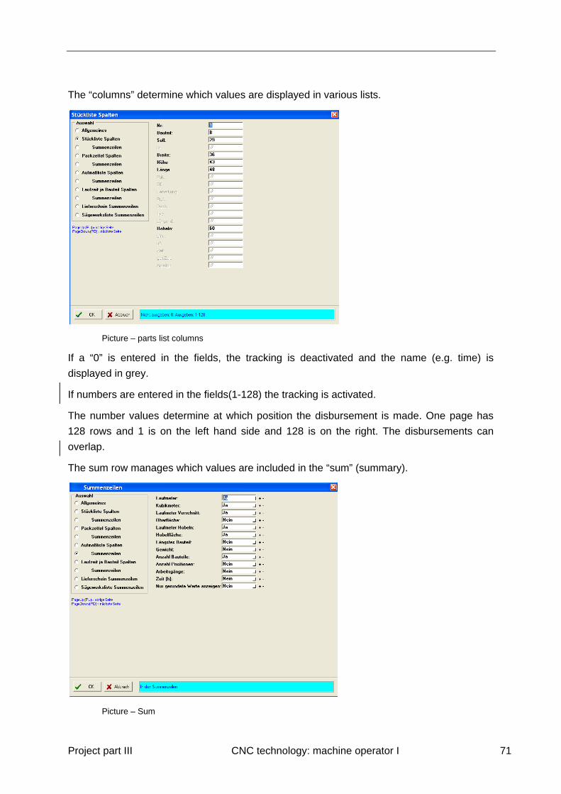
Project part III CNC technology: machine operator I 71
The “columns” determine which values are displayed in various lists.
Picture – parts list columns
If a “0” is entered in the fields, the tracking is deactivated and the name (e.g. time) is
displayed in grey.
If numbers are entered in the fields(1-128) the tracking is activated.
The number values determine at which position the disbursement is made. One page has
128 rows and 1 is on the left hand side and 128 is on the right. The disbursements can
overlap.
The sum row manages which values are included in the “sum” (summary).
Picture – Sum

Project part III CNC technology: machine operator I 72
There is a choice between “yes” and “no” possible.
Sorting of Stock:
Select Options- Sort from the menu to manage the order of a list.
Picture – Bauteil
The picture above shows the sorting function by work piece. The order is determined by the
numbers 1 – 5.
Picture – Bauteil
In this picture the sort function is determined by the length (decreasing). The longest piece of
timber is at the top and the shortest is at the end.
The SPCP allows for inclusion of stock when setting up the saw mill list.
The stock can be listed by cross section, length and grade.

Project part III CNC technology: machine operator I 73
Picture – Inventory List
The list shows timber with the following values C24, 8 x 16 cm and various lengths of 7, 10,
and 13 meter. It is however, not possible to input the quantity, and during processing there is
no reduction. This menu item can be used to reduce rest posts of timber and to ensure
certain cross sections and lengths are always available.
To retrieve a certain list open “lists” in the menu and as per the picture below “cutlist”
Picture – Cut list from the project “Balkenlage”
Another sample for a list is the Sawmill List.

Project part III CNC technology: machine operator I 74
Picture – Sawmill List
When creating the Sawmill list additional details can be set up. This includes groups,
grading, and completed work pieces that can be in- or excluded. The use of stock is also
possible. If the combination of work pieces requires a long piece of timber, e.g. the “select
long timber” function can be used to have the machine feed long pieces of lumber.
Additional length and rounding can be selected under options – lists – General.
Picture –General
Every work piece is calculated with the additional length of 1 cm. Afterwards the rounding to
the closest 5 cm occurs.
The SPCP offers further options for settings when summarizing timber.
When selecting “minimal length” the lists are checked for timber with this minimal length to
find a combination of work pieces. If it is impossible to create one under consideration of
maximum waste the work pieces will be individually under consideration of the additional
length and the rounding added to the sawmill list.
When selecting “maximum length” the machine attempts to find a combination of work
pieces with the maximum length. If it is impossible to create this combination under

Project part III CNC technology: machine operator I 75
consideration of the maximal waste the work pieces will be individually under consideration
of the additional length and the rounding added to the sawmill list.
Automatically optimize the timber according to the rough length of the raw timber: Press
“?” to start the automatic part optimization. You can optimize timbers of different jobs
together to achieve an even more efficient optimization. After entering the length and
dimension of the raw timber a new timber list is created in which the raw timber is listed
along with the corresponding parts.
Manual optimization: Highlight a part in the job list. Press “+”. The manual optimization list
pops up. Press “OK“ to transfer the part to the optimization list. Use “+” and “OK” to transfer
more parts or use “-“ to delete parts from the optimization list it. When all necessary timbers
are on the list, it can be transferred to the cut list by pressing “*”.
Grouping timbers: You have the possibility to nest timbers, e.g. braces, to reduce the
waste of material as shown in a picture:
The sawmill list can be printed, saved and copied into a work processing program.