
T HE CRUSHED E XPERIMENT By: Carlos Sanabria Justin Roose Phillip Munday.
35
THE CRUSHED EXPERIMENT By: Carlos Sanabria Justin Roose Phillip Munday
-
Upload
sandra-mckenzie -
Category
Documents
-
view
221 -
download
2
Transcript of T HE CRUSHED E XPERIMENT By: Carlos Sanabria Justin Roose Phillip Munday.
THE CRUSHED EXPERIMENT
By: Carlos Sanabria Justin Roose Phillip Munday

THE EXPERIMENT We are to apply 10,000 psi of a quasi-
hydrostatic pressure on a 6” diameter pipe
2Figure 1 – Sketch
Pipe under hydrostatic pressure

CONCEPT GENERATION
3
Figure 2 – Concepts
a)Four plates with an incompressible media
b)Fluid Pressure
c)High strength fabric
d)Hose Clamp
e)Segments
Plates Pipe
a)
b)

CONCEPT GENERATION
4
Figure 2 – Concepts
a)Four plates with an incompressible media
b)Fluid Pressure
c)High strength fabric
d)Hose Clamp
e)Segments
c)
d)

CONCEPT GENERATION
5
Figure 2 – Concepts
a)Four plates with an incompressible media
b)Fluid Pressure
c)High strength fabric
d)Hose Clamp
e)Segments
e)

THE DESIGN PROCESS
Figure 3 – Transverse cross section of the pipe being compressed by six sections
6
Outer Ring
Hydrostatic Press
Spacing (incompressible
media)
Pipe

FEA Thinking about these
sections and how close to real hydrostatic pressure these forces will be, we have to find out how many pieces (sections) we need.
An FEA was done to determine the pressure distribution, failure points and strains.
Figure 4 – FEA sample Using 4 sections and a distributed known load
7

TWO SECTIONS
Figure 5 – Two sectionsNot an option!
8
Pressure Distribution (MPa)

FOUR SECTIONS
Figure 6 – Four sectionsStill not uniform
9
Pressure Distribution (MPa)

SIX SECTIONS
Figure 7 – Six sectionsBetter pressure distribution
10
Pressure Distribution (MPa)
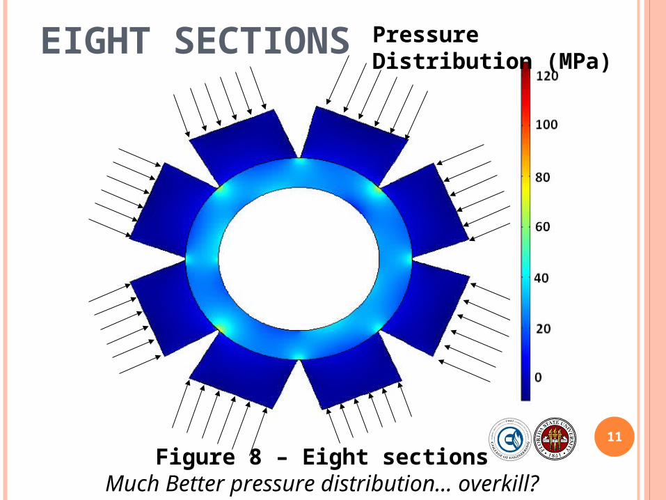
EIGHT SECTIONS
Figure 8 – Eight sectionsMuch Better pressure distribution… overkill?
11
Pressure Distribution (MPa)

FORCE APPLICATION
12
vs.
Screws vs. Hydraulic actuators
Figure 9 – Force ApplicationSide view of the two force application options

MATERIAL SELECTION
Figure 12 – A single section
13
h
d
wF
F
Figure 13 – The hexagonal outer ring
SteelAluminum

FINAL DESIGN (FOR 10,000 PSI)
14
Figure 14 – Final Design for the fall semester
Design for a surface pressure up to 10,000 psi

THE PROBLEM:
15
The strongest actuators that can accommodate our budget are not nearly as strong as our calculations assumed
Our sponsor advised that we should design around the actuator’s force

AVAILABLE ACTUATORS
CONSIDERING OUR BUDGET
Figure 15 – Model Number RW50
16

NEW RING DIMENSIONS AND
FORCES
Figure 16 – New ring Dimensions
14.05 in
20
Five tons of force from each actuator

OPTIMIZING
Figure 17 – New System Layout and next steps
New I-Beam Dimensions
Natural Rubber Insertion
Replacing Actuators
18
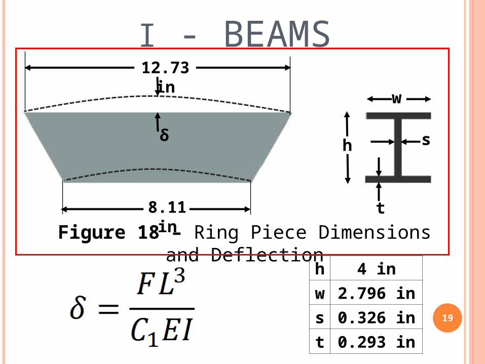
I - BEAMS
h s
t
12.73 in
8.11 in
w
h 4 inw 2.796 ins 0.326 int 0.293 in
19
δ
Figure 18 – Ring Piece Dimensions and Deflection

I - BEAMS
20
NOT SIGNIFICANT!
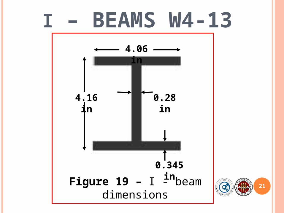
I – BEAMS W4-13
21
4.16 in
4.06 in
0.28 in
0.345 in
Figure 19 – I - beam dimensions

REPLACING ACTUATORS BY STATIONARY
COLUMNS
22
COLUMNS ARE CHARACTERIZED BY IT’S SLENDERNESS
RATIO
L = LENGTH OF THE COLUMN
K = RADIUS OF GYRATION

If the Slenderness Ratio < 10 The column is now bound by the Mechanical Properties
To ensure this: L = 1.94 inch
same length as hydraulic cylinders Diameter > 0.776 inch
Diameter is set to be 1 inch Made out of structural steel ASTM - A36
Same as I-beams
23
REPLACING ACTUATORS BY STATIONARY
COLUMNS

24
REPLACING ACTUATORS BY STATIONARY
COLUMNS
Stress = 12 ksi
Strain = 0.0004
Structural Steel ASTM – A36Elastic Modulus = 29,000 ksi
Yield Stress = 36 ksi

FINAL SYSTEM
Figure 20 – Final System
New I-Beam Dimensions
Natural Rubber Insertion
Columns

NEW FEA
Figure 21 – FEA with a smaller force area
26
F = 10,000lbsStress (ksi)5432
1

WELDING POINTS
Figure 22 – Welding area forces and stresses
27

SAFETY
28
High pressure and high forces are always dangerous to work with
Need to have intimate knowledge of the system to operate
Keep others in close proximity aware of the testing
Eye protection is advised
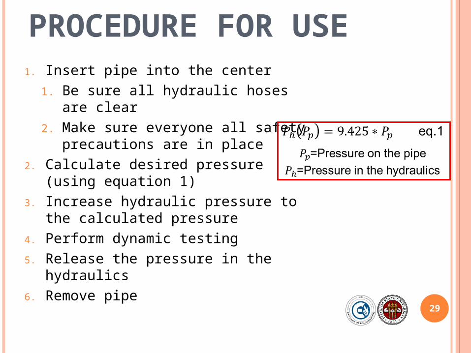
PROCEDURE FOR USE
29
1. Insert pipe into the center1. Be sure all hydraulic hoses are clear2. Make sure everyone all safety
precautions are in place2. Calculate desired pressure (using
equation 1)3. Increase hydraulic pressure to the
calculated pressure4. Perform dynamic testing5. Release the pressure in the hydraulics6. Remove pipe

PIPE PRESSURE VS. HYDRAULIC PRESSURE
30

TESTING
31
Attached a strain gauge on the inside of the pipe Get a relationship between hydraulic pressure and pressure on the
pipe
Put copper wire between the pipe Check to see how quasi-hydrostatic the pressure is
32
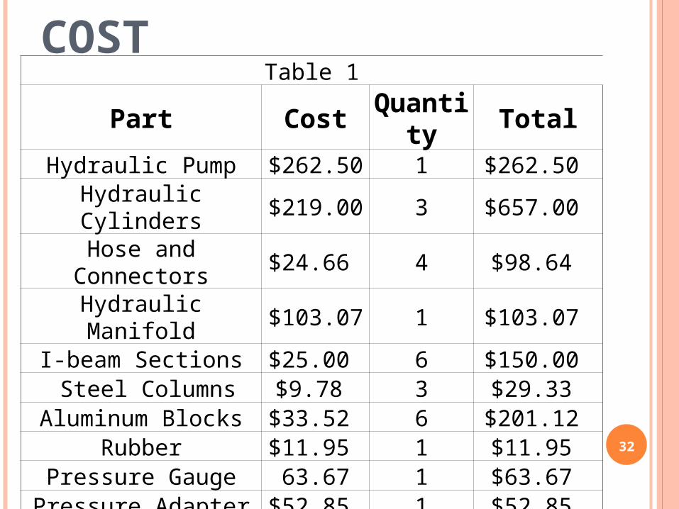
COSTTable 1
Part Cost Quantity TotalHydraulic Pump $262.50 1 $262.50
Hydraulic Cylinders $219.00 3 $657.00 Hose and Connectors $24.66 4 $98.64
Hydraulic Manifold $103.07 1 $103.07 I-beam Sections $25.00 6 $150.00 Steel Columns $9.78 3 $29.33
Aluminum Blocks $33.52 6 $201.12 Rubber $11.95 1 $11.95
Pressure Gauge 63.67 1 $63.67 Pressure Adapter $52.85 1 $52.85
Total Costs $1,630.13

CONCLUSION
33
Max Pipe Pressure = 1061 psi

ACKNOWLEDGMENTS
Dr. Eric Hellstrom
Dr. William Oates
Dr. Janet Wolfson
Dr. Zohrob Hovsapian
Dr. Srinivas Kosaraju
S & H Hydraulics 34
Jeremy Phillips
John Deep
QUESTIONS?
35


