T h e Des ign an d Imp lemen ta tion of Mes sage P assin g ... · T h e Des ign an d Imp lemen ta...
22
The Design and Implementation of Message Passing Services for the BlueGene/L Supercomputer George Alm´ asi 1 , Charles Archer 2 , Jos´ e G. Casta ˜ nos 1 , John Gunnels 1 , C. Chris Erway 1 , Philip Heidelberger 1 , Xavier Martorell 1 , Jos´ e E. Moreira 1 , Kurt Pinnow 2 , Joe Ratterman 2 , Burkhard Steinmacher-burow 1 , William Gropp 3 , and Brian Toonen 3 1 IBM Thomas J. Watson Research Center Yorktown Heights, NY 10598-0218 {gheorghe,castanos,gunnels,cerway,philip,xavim,jmoreira,steinmac}@us.ibm.com 2 IBM Systems Group Rochester, MN 55901 {archerc,kwp,jratt}@us.ibm.com 3 Mathematics and Computer Science Division, Argonne National Laboratory Argonne, IL 60439 {gropp,toonen}@mcs.anl.gov Abstract. The BlueGene/L supercoputer, with 65,536 dual-processor compute nodes, was designed from the group up to support ef£ceint execution of mas- sively parallel message passing programs. Part of this support is an optimized implementation of MPI that leverages the hardware features of BlueGene/L. MPI for BlueGene/L is implemented on top of a more basic message-passing infras- tructure called the message layer. This message layer can be used both to im- plement other higher-level libraries and directly by applications. MPI and the message layer are used in the two modes of operation of BlueGene/L: copro- cessor mode and virtual node mode. Performance measurements show that our message-passing services deliver performance close to the hardware limits of the machine. They also show that dedicating one of the processors of a node to com- munication functions (coprocessor mode) greatly improves the message-passing bandwidth, whereas running two processes per compute node (virtual node mode) can have a positive impact on application performance. 1 Introduction The BlueGene/L supercomputer is a new massively parallel system being developed by IBM in partnership with Lawrence Livermore National Laboratory (LLNL). Blue- Gene/L uses system-on-a-chip integration [5] and a highly scalable architecture [2] to assemble a machine with 65,536 dual-processor compute nodes. When operating at its target frequency of 700 MHz, BlueGene/L will deliver 180 or 360 Tera¤ops of peak computing power, depending on its mode of operation. BlueGene/L is targeted to be- come operational in early 2005. Each BlueGene/L compute node can address only its local memory, making mes- sage passing the natural programming model for the machine. This paper describes how
Transcript of T h e Des ign an d Imp lemen ta tion of Mes sage P assin g ... · T h e Des ign an d Imp lemen ta...
The Design and Implementation of Message PassingServices for the BlueGene/L Supercomputer
George Almasi1, Charles Archer2, Jose G. Castanos1, John Gunnels1, C. ChrisErway1, Philip Heidelberger1, Xavier Martorell1, Jose E. Moreira1, Kurt Pinnow2, JoeRatterman2, Burkhard Steinmacher-burow1, William Gropp3, and Brian Toonen3
1 IBM Thomas J. Watson Research CenterYorktown Heights, NY 10598-0218
{gheorghe,castanos,gunnels,cerway,philip,xavim,jmoreira,steinmac}@us.ibm.com2 IBM Systems GroupRochester, MN 55901
{archerc,kwp,jratt}@us.ibm.com3 Mathematics and Computer Science Division, Argonne National Laboratory
Argonne, IL 60439{gropp,toonen}@mcs.anl.gov
Abstract. The BlueGene/L supercoputer, with 65,536 dual-processor computenodes, was designed from the group up to support ef£ceint execution of mas-sively parallel message passing programs. Part of this support is an optimizedimplementation of MPI that leverages the hardware features of BlueGene/L. MPIfor BlueGene/L is implemented on top of a more basic message-passing infras-tructure called the message layer. This message layer can be used both to im-plement other higher-level libraries and directly by applications. MPI and themessage layer are used in the two modes of operation of BlueGene/L: copro-cessor mode and virtual node mode. Performance measurements show that ourmessage-passing services deliver performance close to the hardware limits of themachine. They also show that dedicating one of the processors of a node to com-munication functions (coprocessor mode) greatly improves the message-passingbandwidth, whereas running two processes per compute node (virtual node mode)can have a positive impact on application performance.
1 Introduction
The BlueGene/L supercomputer is a new massively parallel system being developedby IBM in partnership with Lawrence Livermore National Laboratory (LLNL). Blue-Gene/L uses system-on-a-chip integration [5] and a highly scalable architecture [2] toassemble a machine with 65,536 dual-processor compute nodes. When operating at itstarget frequency of 700 MHz, BlueGene/L will deliver 180 or 360 Tera¤ops of peakcomputing power, depending on its mode of operation. BlueGene/L is targeted to be-come operational in early 2005.
Each BlueGene/L compute node can address only its local memory, making mes-sage passing the natural programming model for the machine. This paper describes how
2
we designed and implemented application-level message passing services for Blue-Gene/L. The services include both an implementation of MPI [12] as well as a morebasic message-passing infrastructure called the message layer.
Our starting point for MPI on BlueGene/L [3] is the MPICH2 library [1], fromArgonne National Laboratory. MPICH2 is architected with a portability layer called theAbstract Device Interface, version 3 (ADI3), which simpli£es the job of porting it todifferent architectures. With this design, we could focus on optimizing the constructsthat were of importance to BlueGene/L.
MPI for BlueGene/L was built on top of the BlueGene/L message layer. This lower-level message passing library if speci£c to BlueGene/L, with an architecture that closelyre¤ects the hardware architecture of the machine. The message layer was designed tosupport the implementation of higher-level libraries, such as MPI. However, it can alsobe used directly by application programs that want to have a more direct path to hard-ware features.
BlueGene/L is a feature-rich machine. A good implementation of message passingservices in BlueGene/L needs to leverage those features to deliver high-performancecommunication services to applications. The BlueGene/L compute nodes are intercon-nected by two high-speed networks: a three-dimensional torus network that supportsdirect point-to-point communication and a tree network with support for broadcast andreduction operations. Those networks are mapped to the address space of user processesand can directly be used by a message passing library. We will show how we archi-tected our message passing implementation to take advantage of both memory mappednetworks.
Another important architectural feature of BlueGene/L is its dual-processor com-pute nodes. A compute node can operate in one of two modes. In coprocessor mode,a single process, spanning the entire memory of the node, can use both processors byrunning one thread on each processor. In virtual node mode, two single-threaded pro-cesses, each using half of the memory of the node, run on one compute node, with eachprocess bound to one processor. This creates the need for two modes in our messagepassing services, with different performance impacts.
We validate our MPI implementation on BlueGene/L by analyzing the performanceof various benchmarks on 32- and 512-node prototypes. The prototypes were built us-ing second-generation BlueGene/L chips operating at 700 MHz. We use microbench-marks to assess how well MPI performs compared to the limits of the hardware andhow different modes of operation within MPI compare to each other. We use the NASParallel Benchmarks to demonstrate the bene£ts of virtual node mode when executingcomputation-intensive benchmarks. Although the focus of our performance study is onMPI, as that is what most applications will use, we also report results measured directlyon the message layer. These results help us quantify the overheads imposed by MPI andprovide guidance for future implementations of other higher-level libraries.
The rest of this paper is organized as follows. Section 2 presents an overview of thehardware and software architectures of BlueGene/L. Section 3 discusses those detailsof BlueGene/L hardware and software that were particularly in¤uential to our MPI im-plementation. Section 4 presents the architecture of our MPI implementation. Section 5describes the basic architecture of the BlueGene/L message layer, while Sections 6 and

3
7 focus on point-to-point and collective operations in the message layer, respectively.Section 8 describes and discusses the experimental results on the prototype machinesthat validate our approach. Finally, Section 9 contains our conclusions.
2 An overview of the the BlueGene/L supercomputer
The BlueGene/L hardware [2] and system software [4] have been extensively describedelsewhere. In this section we present a short summary of the BlueGene/L architectureto serve as background to the following sections.
The 65,536 compute nodes of BlueGene/L are based on a custom system-on-a-chip design that integrates embedded low power processors, high performance networkinterfaces, and embedded memory. The low power characteristics of this architecturepermit a very dense packaging. One air-cooled BlueGene/L rack contains 1024 computenodes (2048 processors) with a peak performance of 5.7 Tera¤ops.
The BlueGene/L chip incorporates two standard 32-bit embedded PowerPC 440processors with private L1 instruction and data caches, a small 2 kB L2 cache/prefetchbuffer and 4 MB of embedded DRAM, which can be partitioned between shared L3cache and directly addressable memory. A compute node also incorporates 512MB ofDDR memory.
The standard PowerPC 440 cores are not designed to support multiprocessor archi-tectures: the L1 caches are not coherent and the processor does not implement atomicmemory operations. To overcome these limitations BlueGene/L provides a variety ofcustom synchronization devices in the chip such as the lockbox (a limited numberof memory locations for fast atomic test-and-sets and barriers) and 16 KB of sharedSRAM.
Each processor is augmented with a dual ¤oating-point unit consisting of two 64-bit¤oating-point units operating in parallel. The dual ¤oating-point unit contains two 32× 64-bit register £les, and is capable of dispatching two fused multiply-adds in everycycle, i.e. 2.8 GFlops/s per node at the 700MHz target frequency. When both processorsare used, the peak performance is doubled to 5.6 GFlops/s.
In addition to the 65,536 compute nodes, BlueGene/L contains a variable numberof I/O nodes (1 I/O node to 64 compute nodes in the current con£guration) that connectthe computational core with the external world. We call the collection formed by oneI/O node and its associated compute nodes a processing set. Compute and I/O nodesare built using the same BlueGene/L chip, but I/O nodes have the Ethernet networkenabled.
The main network used for point-to-point messages is the torus. Each compute nodeis connected to its 6 neighbors through bi-directional links. The 64 racks in the fullBlueGene/L system form a 64×32×32 three-dimensional torus. The network hardwareguarantees reliable, deadlock free delivery of variable length packets.
The tree is a con£gurable network for high performance broadcast and reductionoperations, with a latency of 2.5 microseconds for a 65,536-node system. It also pro-vides point-to-point capabilities. The global interrupt network provides con£gurableOR wires to perform full-system hardware barriers in 1.5 microseconds

4
All the torus, tree and global interrupt links between midplanes (a 512-computenode unit of allocation) are wired through a custom link chip that performs redirec-tion of signals. The link chips provide isolation between independent partitions whilemaintaining fully connected networks within a partition.
BlueGene/L system software architecture: User application processes run exclu-sively on compute nodes under the supervision of a custom Compute Node Kernel(CNK). The CNK is a simple, minimalist runtime system written in approximately 5000lines of C++ that supports a single application running by a single user in each BG/Lnode. It provides exactly two threads running one on each PPC440 processor. The CNKdoes not require or provide scheduling and context switching. Physical memory is stati-cally mapped, protecting a few kernel regions from user applications. Porting scienti£capplications to run into this new kernel has been a straightforward process because weprovide a standard Glibc runtime system with most of the Posix system calls.
Many of the CNK system calls are not directly executed in the compute node, but arefunction shipped through the tree to the I/O node. For example, when a user applicationperforms a write system call, the CNK sends tree packets to the I/O node managingthe processing set. The packets are received on the I/O node by a daemon called ciod.This daemon buffers the incoming packets, performs a Linux write system call againsta mounted £lesystem, and returns the status information to the CNK through the tree.The daemon also handles job start and termination on the compute nodes.
I/O nodes run the standard PPC Linux operating system and implement I/O andprocess control services for the user processes running on the compute nodes. Wemounta small ramdisk with system utilities to provide a root £lesystem.
The system is complemented by a control system implemented as a collection ofprocesses running in an external computer. All the visible state of the BlueGene/L ma-chine is maintained in a commercial database. We have modi£ed the BlueGene/L mid-dleware (such as LoadLeveler and mpirun) to operate through the ciod system ratherthan launching individual daemons on all the nodes.
3 Hardware and system software impact on MPI implementation
In this section we present a detailed discussion of the BlueGene/L features that have asigni£cant impact on the MPI implementation.
The torus network guarantees deadlock-free delivery of packets. Packets are routedon an individual basis, using one of two routing strategies: a deterministic routing al-gorithm, in which all packets follow the same path along the x, y, z dimensions (in thisorder); and a minimal adaptive routing algorithm, which permits better link utilizationbut allows consecutive packets to arrive at the destination out of order.Ef£ciency: The torus packet length is between 32 and 256 bytes in multiples of
32. The £rst 16 bytes of every packet contain destination, routing and software headerinformation. Therefore, only 240 bytes of each packet can be used as payload. For every256 bytes injected into the torus, 14 additional bytes traverse the wire with CRCs etc.Thus the ef£ciency of the torus network is η = 240
270 = 89%.

5
Link bandwidth: Each link delivers two bits of raw data per CPU cycle (0.25Bytes/cycle), or η × 0.25 = 0.22 Bytes/cycle of payload data. This translates into154 MBytes/s/link at the target 700 MHz frequency.Per-node bandwidth:Adding up the raw bandwidth of the 6 incoming + 6 outgoing
links on each node, we obtain 12 × 0.25 = 3 bytes/cycle per node. The correspondingbidirectional payload bandwidth is 2.64 bytes/cycle/node.Reliability: The network guarantees reliable packet delivery. In any given link, it
resends packets with errors, as detected by the CRC. Irreversible packet losses are con-sidered catastrophic and stop the machine. The communication library considers themachine to be completely reliable.Network ordering semantics:MPI ordering semantics enforce the order in which
incoming messages are matched against the queue of posted messages. Adaptivelyrouted packets may arrive out of order, forcing the MPI library to reorder them be-fore delivery. Packet re-ordering is expensive because it involves memory copies andrequires packets to carry additional sequence and offset information. On the other hand,deterministic routing leads to more network congestion and increased message latencyeven on lightly used networks.
The tree network serves a dual purpose. It is designed to performMPI collective oper-ations ef£ciently, but it is also the main mechanism for communication between I/O andcompute nodes. The tree supports point-to-point messages of £xed length (256 bytes),delivering 4 bits of raw data per CPU cycle (350 Mbytes/s). It has reliability guaranteesidentical to the torus.Ef£ciency: The tree packet length is £xed at 256 bytes, all which can be used for
payload. 10 additional bytes are used with each packet for operation control and linkreliability. Thus, the ef£ciency of the tree network is η = 256
266 = 96%.Collective operations: An ALU in the tree network hardware can combine incom-
ing and local packets using bitwise and integer operations, and forward the resultingpacket along the tree. Floating-point reductions can be performed in two phases, one tocalculate the maximum exponent and another to add the normalized mantissas.Packet routing on the tree network is based on packet classes. Tree network con-
£guration is a global operation that requires the con£guration of all nodes in a jobpartition. For that reason we only support operations on MPI COMM WORLD.
CPU/network interface: The torus, tree and barrier networks are partially mappedinto user-space memory. Torus and tree packets are read and written with special 16-byte SIMD load and store instructions of the custom FPUs.Alignment: The SIMD load and store instructions used to read and write network
packets require that memory accesses be aligned to a 16 byte boundary. The MPI librarydoes not have control over the alignment of user buffers. In addition, the sending and re-ceiving buffer areas can be aligned at different boundaries, forcing packet re-alignmentthrough memory-to-memory copies.Network access overhead: Torus/tree packet reads into aligned memory take about
204 CPU cycles. Packet writes can take between 50 and 100 cycles, depending on thewhether the packet is being sent from cache or main memory.
6
CPU streaming memory bandwidth is another constraint of the machine. For MPIpurposes we are interested mostly in the bandwidth for accessing large contiguousmemory buffers. These accesses are typically handled by prefetch buffers in the L2cache, resulting in a bandwidth of about 4.3 bytes/cycle.
We note that the available bandwidth of main memory and the torus and tree net-work are in the same order of magnitude. Performing memory copies on this machine toget data into/from the torus results in reduced performance. It is imperative that networkcommunication be zero-copy wherever possible.
Inter-core cache coherency: The two processors in a node are not cache coherent.Software must take great care to insure that coherency is correctly handled in software.Coherency handled at the granularity of the CPUs’ L1 cache lines: 32 bytes. Therefore,data structures shared by the CPUs should be aligned at 32-byte boundaries to avoidcoherency problems.
4 Architecture of BlueGene/L MPI
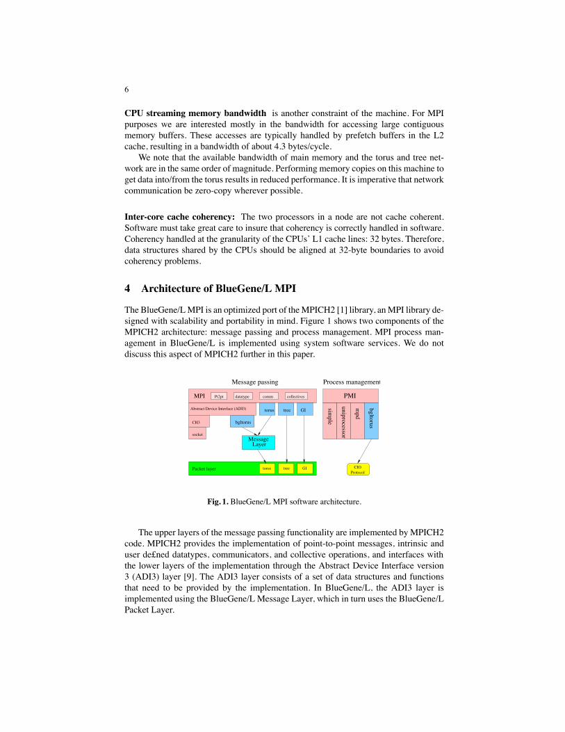
The BlueGene/LMPI is an optimized port of theMPICH2 [1] library, anMPI library de-signed with scalability and portability in mind. Figure 1 shows two components of theMPICH2 architecture: message passing and process management. MPI process man-agement in BlueGene/L is implemented using system software services. We do notdiscuss this aspect of MPICH2 further in this paper.
Protocol
collectivescommdatatypePt2pt
GItreetorus
MessageLayer
Abstract Device Interface (ADI3)
CH3
socket
torus tree GI
Packet layer
Message passing Process management
bgltorus
mpd
uniprocessor
simple
PMI
CIO
MPI
bgltorus
Fig. 1. BlueGene/L MPI software architecture.
The upper layers of the message passing functionality are implemented by MPICH2code. MPICH2 provides the implementation of point-to-point messages, intrinsic anduser de£ned datatypes, communicators, and collective operations, and interfaces withthe lower layers of the implementation through the Abstract Device Interface version3 (ADI3) layer [9]. The ADI3 layer consists of a set of data structures and functionsthat need to be provided by the implementation. In BlueGene/L, the ADI3 layer isimplemented using the BlueGene/L Message Layer, which in turn uses the BlueGene/LPacket Layer.

7
The ADI layer is described in terms of MPI requests (messages) and functions tosend, receive, and manipulate these requests. The BlueGene/L implementation of ADI3is called bgltorus. It implements MPI requests in terms of Message Layer messages,assigning one message to every MPI request. Message Layer messages operate throughcallbacks. Messages corresponding to send requests are posted in a send queue. Whena message transmission is £nished, a callback is used to inform the sender. Correspond-ingly, there are callbacks on the receive side to signal the arrival of new messages.Those callbacks perform matching of incoming Message Layer messages to the list ofMPI posted and unexpected requests.The BlueGene/L Message Layer is an active message system [8, 11, 14, 15] that
implements the transport of arbitrary-sized messages between compute nodes using thetorus network. It can also broadcast data, using special torus packets that are depositedon every node along the route they take. The message layer breaks messages into £xed-size packets and uses the packet layer to send and receive the individual packets. At thedestination, the Message Layer is responsible for reassembling the packets, which mayarrive out of order, back into a message.
The message layer addresses nodes using the equivalent of MPI COMM WORLDranks. Internally, it translates these ranks into physical torus x, y, z coordinates, that areused by the Packet Layer. The mapping of ranks to torus coordinates is programmableby the user, and can be used to optimize application performance by choosing a map-ping that support the logical communication topology of the application.The Packet Layer is a very thin stateless layer of software that simpli£es access to
the BlueGene/L network hardware. It provides functions to read and write the torus/treehardware, as well as to poll the state of the network. Torus packets typically consist of240 bytes of payload and 16 bytes of header information. Tree packets consist of 256bytes of data and a separate 32-bit header. To help the Message Layer implement zero-copy messaging protocols, the packet layer provides convenience functions that allowsoftware to “peek” at the header of an incoming packet without incurring the expenseof unloading the whole packet from the network.
5 Message layer architecture
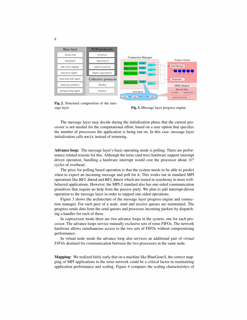
Figure 2 shows the structural and functional composition of the message layer. It isdivided into three main categories - basic functional support, point-to-point commu-nication primitives (or protocols) and collective communication primitives. The baselayer acts as a support infrastructure for the implementation of all the communicationprotocols.
Initialization: The message layer takes full control of a number of hardware resourcesin the BlueGene/L system - namely all the torus hardware FIFOs. The message layer isnot equipped to share these objects; therefore there should never be two message layerobjects instantiated in the same process.
Initialization is a fairly complicated process. It initializes all state machines, therank mapping subsystem and decides the operating mode (virtual node mode, heatermode or coprocessor mode) based on input from the caller.
8
Base layer
Collective protocols
Pt2Pt protocols
message posting support
packet layer primitives
virtual node mode support
coprocessor support
rank to torus mapping
initialization
advance loop
broadcast
alltoall[v]
adaptive eager protocol
rendezvous protocol
eager protocol
1P protocol
Fig. 2. Structural composition of the mes-sage layer
Rank 0 (0,0,0)
Rank 2 (0,0,2)
Rank 1 (0,0,1)
Rank n (x,y,z)
sendQ
sendQ
sendQ
sendQ
recv
recv
recv
. . .msg1 msg2 msgP
Send Manager
recv
Dispatcher. . .
. . .
Send Queue
Connection ManagerProgress Engine
MPID_RequestMessage Data
user buffer
protocol & state info
(un)packetizer
Fig. 3.Message layer progress engine
The message layer may decide during the initialization phase that the current pro-cessor is not needed for the computational effort, based on a user option that speci£esthe number of processors the application is being run on. In this case, message layerinitialization calls exit instead of returning.
Advance loop: The message layer’s basic operating mode is polling. There are perfor-mance related reasons for this. Although the torus (and tree) hardware support interruptdriven operation, handling a hardware interrupt would cost the processor about 103
cycles of overhead.The price for polling based operation is that the system needs to be able to predict
when to expect an incoming message and poll for it. This works out in standard MPIoperations like MPI Send and MPI Recv which are issued in synchrony in most well-behaved applications. However, the MPI-2 standard also has one-sided communicationprimitives that require no help from the passive party. We plan to add interrupt-drivenoperation to the message layer in order to support one-sided operations.
Figure 3 shows the architecture of the message layer progress engine and connec-tion manager. For each peer of a node, send and receive queues are maintained. Theprogress sends data from the send queues and processes incoming packets by dispatch-ing a handler for each of these.
In coprocessor mode there are two advance loops in the system, one for each pro-cessor. The advance loops service mutually exclusive sets of torus FIFOs. The networkhardware allows simultaneous access to the two sets of FIFOs without compromisingperformance.
In virtual node mode the advance loop also services an additional pair of virtualFIFOs destined for communication between the two processors in the same node.
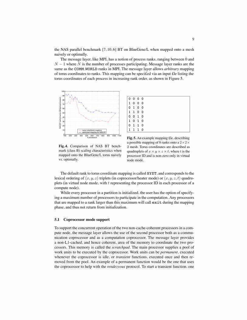
Mapping: We realized fairly early that on a machine like BlueGene/L the correct map-ping of MPI applications to the torus network could be a critical factor in maintainingapplication performance and scaling. Figure 4 compares the scaling characteristics of
9
the NAS parallel benchmark [7, 10, 6] BT on BlueGene/L when mapped onto a meshnaively or optimally.
The message layer, like MPI, has a notion of process ranks, ranging between 0 andN − 1 where N is the number of processes participating. Message layer ranks are thesame as the COMM WORLD ranks in MPI. The message layer allows arbitrary mappingof torus coordinates to ranks. This mapping can be speci£ed via an input £le listing thetorus coordinates of each process in increasing rank order, as shown in Figure 5.
100 200 300 400 500 600 700 800 900 1000 11000
10
20
30
40
50
60
70
80
90
100
# processors
NAS
BT p
erfo
rman
ce (M
Ops
/s/p
roce
ssor
)
naive (standard) mappingoptimized mapping for NAS BT
Fig. 4. Comparison of NAS BT bench-mark (class B) scaling characteristics whenmapped onto the BlueGene/L torus naivelyvs. optimally.
0 0 0 01 0 0 00 1 0 01 1 0 00 0 1 01 0 1 00 1 1 01 1 1 0
Fig. 5.An example mapping £le, describinga possible mapping of 8 ranks onto a 2×2×2 mesh. Torus coordinates are described asquadruplets of x× y × z × t, where t is theprocessor ID and is non-zero only in virtualnode mode.
The default rank to torus coordinate mapping is called XYZT, and corresponds to thelexical ordering of (x, y, z) triplets (in coprocessor/heater mode) or (x, y, z, t) quadru-plets (in virtual node mode, with t representing the processor ID in each processor of acompute node).
While every processor in a partition is initialized, the user has the option of specify-ing a maximum number of processors to participate in the computation. Any processorsthat are mapped to a rank larger than this maximum will call exit during the mappingphase, and thus not return from initialization.
5.1 Coprocessor mode support
To support the concurrent operation of the two non-cache-coherent processors in a com-pute node, the message layer allows the use of the second processor both as a commu-nication coprocessor and as a computation coprocessor. The message layer providesa non-L1-cached, and hence coherent, area of the memory to coordinate the two pro-cessors. This memory is called the scratchpad. The main processor supplies a pool ofwork units to be executed by the coprocessor. Work units can be permanent, executedwhenever the coprocessor is idle, or transient functions, executed once and then re-moved from the pool. An example of a permanent function would be the one that usesthe coprocessor to help with the rendezvous protocol. To start a transient function, one

10
invokes the co start function provided by the message layer. The main processorwaits for the completion of the work unit by invoking the co join function.
The coprocessor can also help with communication tasks. One of the permanentwork units is a communication thread that runs all the time. Administrative data formessages received by the coprocessor is held in the scratchpad. Messages processedby the coprocessor are always aligned at cache line boundaries, and at the end of thereception the two processors cooperatively enforce coherency in software.
5.2 Virtual node mode support
The kernel in the compute nodes also supports a virtual node mode of operation for themachine. In this mode the kernel runs two separate processes in each compute node.Node resources (primarily the memory and the torus network) are evenly split betweenboth processes. In virtual node mode, an application can use both processors in a nodesimply by doubling its number of tasks, without having to explicitly handle cache co-herence issues. The now distinct tasks running in the two CPUs of a compute node haveto communicate to each other. We have solved this problem by implementing a virtualtorus device, serviced by a virtual packet layer, in the scratchpad memory. Virtual FI-FOs make portions of the scratchpad look like a send FIFO to one of the processors anda receive FIFO to the other. Access to the virtual FIFOs is mediated with help from thehardware lockboxes. Code for scratchpad setup is the same for both coprocessor modeand virtual node mode.
Virtual node doubles the number of tasks in the message layer; it also introduces are£nement in the addressing of tasks. As already shown in Figure 5, instead of beingaddressed with a triplet (x, y, z) denoting the torus coordinates, tasks are addressedwith quadruplets (x, y, z, t) where t is the processor ID (0 or 1) in the current node. Incoprocessor mode t is always 0.
5.3 Packet layer primitives
The message layer needs to perform three functions to function correctly: it needs tocheck the status of the hardware FIFOs, and it needs to inject and extract packets fromthe FIFOs. As will be seen later, one of the most critical performance limitations ofthe message layer is the number of CPU cycles spent handling each individual networkpacket. The absolute limits of packet read/write times are about 100 CPU cycles forwrites and 204 CPU cycles for reads. The larger read overhead is caused by a combina-tion of relatively large read latency and a limitation of the PPC 440 processor causingit to stall after 4 consecutive reads from the network hardware.
The best way to keep packet processing times low is to avoid additional memorycopies in the software stack. Thus, an outgoing packet should be sent directly from thesend buffer; an incoming packet should be read directly into its £nal destination. Bothof these are nontrivial to achieve.
We dispensed with additional memory copies during packet reads by using partialpackets. Instead of reading a whole packet into a temporary buffer and then copyingthe payload portion to the actual destination, the message layer uses reads out only thepacket header and calls a packet handler based on the contents of the header. The packet
11
0 1 2 3 4 5 6 7 8 9 10 11 12 13 14 15150
200
250
300
350
400
450
500
550
Alignment offset (Bytes)
Pack
et re
ad ti
me
(Cyc
les)
aligned recv + memcpycombined recv + realignmentIdeal cycle count
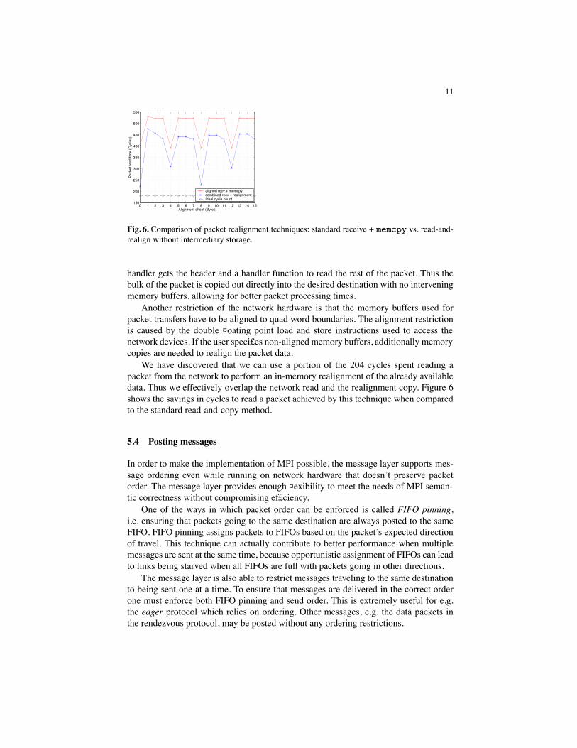
Fig. 6. Comparison of packet realignment techniques: standard receive + memcpy vs. read-and-realign without intermediary storage.
handler gets the header and a handler function to read the rest of the packet. Thus thebulk of the packet is copied out directly into the desired destination with no interveningmemory buffers, allowing for better packet processing times.
Another restriction of the network hardware is that the memory buffers used forpacket transfers have to be aligned to quad word boundaries. The alignment restrictionis caused by the double ¤oating point load and store instructions used to access thenetwork devices. If the user speci£es non-aligned memory buffers, additionally memorycopies are needed to realign the packet data.
We have discovered that we can use a portion of the 204 cycles spent reading apacket from the network to perform an in-memory realignment of the already availabledata. Thus we effectively overlap the network read and the realignment copy. Figure 6shows the savings in cycles to read a packet achieved by this technique when comparedto the standard read-and-copy method.
5.4 Posting messages
In order to make the implementation of MPI possible, the message layer supports mes-sage ordering even while running on network hardware that doesn’t preserve packetorder. The message layer provides enough ¤exibility to meet the needs of MPI seman-tic correctness without compromising ef£ciency.
One of the ways in which packet order can be enforced is called FIFO pinning,i.e. ensuring that packets going to the same destination are always posted to the sameFIFO. FIFO pinning assigns packets to FIFOs based on the packet’s expected directionof travel. This technique can actually contribute to better performance when multiplemessages are sent at the same time, because opportunistic assignment of FIFOs can leadto links being starved when all FIFOs are full with packets going in other directions.
The message layer is also able to restrict messages traveling to the same destinationto being sent one at a time. To ensure that messages are delivered in the correct orderone must enforce both FIFO pinning and send order. This is extremely useful for e.g.the eager protocol which relies on ordering. Other messages, e.g. the data packets inthe rendezvous protocol, may be posted without any ordering restrictions.

12
5.5 Non-contiguous data delivery
Themessage layer is able to handle arbitrary collections of data, including non-contiguousdata descriptors described by MPICH2 data loops. The Message Layer incorporatesa number of complex data packetizers and unpacketizers that satisfy the multiple re-quirements of 16-byte aligned access to the torus, arbitrary data layouts, and zero-copyoperations.
6 Point-to-point Protocols in the message layer
The ultimate goal of point-to-point primitives in the message layer is to support an ef£-cient implementation of MPI. For this reason, there is a range of point-to-point messagetransmission primitives available in the message layer, each suited for a different mes-sage sizes and having different latency and bandwidth characteristics. Some protocols,like the one-packet protocol, are limited as far as maximum message size, but provideextremely good latency; the rendezvous protocol, by contrast, works for any messagesize but provides poor latency. The BlueGene/L MPI implementation uses all theseprotocols depending on communication requirements. A discussion of the speci£cs ofthe MPI implementation is beyond the scope of this paper; however, the names of themessage layer point-to-point primitives should give a good indication of their intendedpurpose in the MPI implementation.
All point-to-point messaging primitives share the same design philosophy. Namely,all primitives are non-blocking and results of user actions are announced through call-backs registered by the user.
In order to send a message, the user of the message layer needs to have access tothe send buffer as well as memory for the message state (the latter can be allocated byasking the message layer to provide the memory). The user initializes the message stateand attaches the send buffer, and then posts the message by calling a form of the postmethod in the message layer. The user is also responsible for providing the name of thecallback function to be called at the end of the send process.
At the receiving end an incoming message is noted by calling the recvnew call-back previously registered by the user. In the callback the user is responsible for provid-ing memory both for the message data structure as well as for the receive buffer, and thename of the recvdone callback which will be invoked when the receive is complete.
The message layer completion semantics are local: the senddone callback iscalled when the send buffer can be reused, but not guarantees are made about the stateof reception at the receiver. The recvdone callback is called when the receive bufferis ready to be used by the user. The user is forbidden to touch the send/receive bufferuntil the senddone/recvdone callback is called.
Point-to-point messaging is implemented with the help of a number of packetizersand unpacketizers. These are functions that prepare BlueGene/L network packets fromthe send buffer and piece the packets together into the another buffer at the receivingend. The packetizers support both contiguous and non-contiguous user buffers. Becausepackets on the network can arrive out of order, the unpacketizer has to be able to dealwith packets of the same message arriving in any sequence.

13
6.1 The eager protocol
The eager protocol is one of the simplest both in terms of programmer’s interface andimplementation. It guarantees ordered delivery of messages by enforcing by both FIFOpinning and post send order. All eager protocol packets are sent using deterministicrouting, so that the packets themselves arrive in order at the receiver. This means thatunpacking the eager protocol is extremely simple, with a running counter keeping trackof the message offset both at the sender and the receiver.
The programmer’s interface for the eager protocol consists of constructor functionsto initialize eager messages and the three callbacks recvnew, recvdone and send-done.
In addition to the send buffer, every eager message also transmits a £xed size mem-ory buffer that may contain message metadata. The contents of this buffer is opaque tothe message layer; in the BlueGene/L MPI implementation we use it to transmit MPImatching information, such as the sender’s MPI rank, the message tag and the contextidenti£er.
6.2 The one-packet protocol
The one packet protocol is a simpli£ed version of the eager protocol for cases whenthe send buffer £ts into a single packet. The one packet protocol saves overhead costsby virtue of a very simple packetizer. The programmer’s API is also simpler than ea-ger message’s, because there is no need for the recvdone callback. The recvnewcallback carries with it a temporary message buffer, and it is the user’s responsibility tocopy its contents before the callback returns.
6.3 The rendezvous protocol
Both the one-packet and eager protocols suffer from two major de£ciencies. First, datapackets are deterministically routed to retain ordering, resulting in inef£cient use of thetorus network. Second, the eager and one-packet protocols are unable make use of thecoprocessor for packet delivery.
The rendezvous protocol £xes both these problems. The only packet sent via de-terministic route is the initial “scout” packet that essentially asks permission from thereceiver to send data. The receiver returns an acknowledgment, followed by the datatransfer from the sender.
In our current implementation of the rendezvous protocol the burden of message re-ception can be carried by the coprocessor, subject to availability, cache coherency andalignment constraints. Thus, the receiver’s coprocessor is able to handle any packetscarrying contiguous data aligned at cache line boundaries (in order to avoid false shar-ing at cache line boundaries). This improves the ef£ciency of simultaneous messageexchanges with multiple neighbors.
The unpacking of rendezvous protocol packets is somewhat more complicated thanthat of eager packets. The packets can arrive out of order. We chose a solution in whichthe sender and receiver exchange the absolute address of the receive buffer before anydata is sent; thus each packet is addressed directly to a particular memory address in the
14
receiver. Thus, all the unpacketizer has to do is copy each incoming packet to the spec-i£ed memory address, count the packets until the required amount of data has ¤own in.This makes for streamlined handling of packet reception, again improving the ef£ciencyof multiple neighbor exchanges.
6.4 The adaptive eager protocol
The adaptive eager protocol is a version of the eager protocol that uses no determin-istically routed packets. Instead it solves the message ordering problem by sendinga con£rmation packet every time the £rst packet of a new message is received. Thesender can only start sending the next message after it has received con£rmation that atleast one packet of the previous message has been seen by the receiver. This techniqueensures that the receiver sees the £rst packet of each message in order, although it doesnot guarantee the order of message completion either at the sender or receiver.
The obvious drawback of this solution is that there is a mandatory waiting time ofat least one network round trip between subsequent message sends. This is not an issueif messages to the same node are sent infrequently - such as in a chaotic communicationpattern, where nodes talk to many other nodes - because it is likely that by the time thenext message is ready to be sent the previous message has been acknowledged by thereceiver.
We believe that the adaptive eager protocol will become more important as the Blue-Gene/L machine scales beyond 20,000 processors, and the number of nodes that arerelatively far apart grows. On a large network deterministically sent eager messages aremore likely to cause traf£c hotspots. The adaptive eager protocol will be in position tosolve that problem.
7 MPI collective operation support in the message layer
It is typical of an MPI implementation to implement collective communication in termsof point-to-point messages. This is certainly the case for MPICH2, the framework usedby BlueGene/L MPI. But on the BlueGene/L platform the default collective implemen-tations of MPICH2 suffer from low performance, for at least three reasons:
– The MPICH2 collectives are written with a crossbar-type network in mind, and notfor special network topologies like the BlueGene/L torus network. Thus the defaultimplementation more often than not suffers from poor mapping (see Section 5).
– Point-to-point messaging in BlueGene/L MPI has a high messaging overhead, dueto the relative slowness of the CPU when compared to the network speed. Thus,implementing e.g. MPI broadcast in terms of a series of point-to-point messageswill result in poor behavior at short message sizes, where overhead dominates theexecution time of the collective.
– Some of the network hardware’s performance-enhancing properties are hidden whenusing only standard point-to-point messaging. A good example of this is the use ofthe deposit bit, a feature of the network hardware that lets packets be “deposited”on every node they touch on the way to the destination.
15
Our work on collective communication in the message layer has just begun. Wehave message layer based implementations of MPI Bcast and MPI Alltoall[v].The broadcast implementation bene£ts from all three factors we have enumerated - ithas lower overhead, is torus/mesh aware and uses the special deposit bit sends providedby network hardware. The alltoall implementation is somewhat immature - although itbene£ts from lower overhead it has a lower target bandwidth because it uses a type ofpacket with fewer payload bytes. Our short term future plans include implementationsof MPI Barrier and MPI Allgatherv as well as MPI Allreduce. Our primaryfocus is on these primitives because they are in demand by the people doing applica-tions tuning on BlueGene/L today. In particular, broadcast, allgather and barrier areheavily used by the ubiquitous HPL benchmark that determines the TOP500 placementof BlueGene/L.
8 Performance analysis
In this section we discuss the performance characteristics of the MPI library. We £rstpresent microbenchmark results that analyze different aspects of our current MPI imple-mentation. We compare different message passing protocols. We present result compar-ing processor effectiveness in coprocessor mode as well as virtual node mode. Finally,we analyze BlueGene/L-speci£c implementations of common collectives.
For measuring performance we used various microbenchmarks, written both on topof the message layer as well as using MPI as a driver for the message layer. These aresome of the same benchmarks we actually used to tune the message layer and MPI. Weconsider these benchmarks to be extremely useful in pinpointing performance de£cien-cies of the message layer (and therefore, of MPI).
For our evaluation, we had several systems available, made of both £rst and secondgeneration chips. The £nal runs presented in this paper were, however, all made onsecond generation chips running at 700 MHz. Most of our micro-benchmark runs weremade on 32 node systems. Scalability studies were performed on systems consisting ofup to 512 nodes.
8.1 Point-to-point message latency
Figure 7 shows the half-roundtrip latency of 1-byte messages sent with all of the fourpoint-to-point protocols. Latencies were measured with message layer and MPI ver-sions Dave Turner’s mpipong program [13]. Unsurprisingly, the one-packet protocolhas the lowest overhead, about 1600 cycles. The highest overhead by far belongs to therendezvous protocol, with the two eager variants in the middle of the range. When mea-sured from within MPI, the latency numbers increase drastically due to the additionalsoftware overhead. All measurements are shown both in cycles and in µs, assuming a700 MHz clock speed.
MPI adds about 750 cycles of overhead in the case of the one-packet protocol, andmore than 1300 cycles in the case of the eager protocol; in the case of the adaptive eagerprotocol MPI overhead also measures the time required to get the next token from thereceiver; hence MPI time more than doubles compared to the message layer’s timing.

16
Protocol name msglayer MPIcycles µs cycles µs
one-packet 1600 2.29 2350 3.35eager 2700 3.86 4000 5.71
adaptive eager 3300 4.71 11000 15.71rendezvous 12000 17.14 17500 25.0
Fig. 7. Roundtrip latency comparison of all pro-tocols 0 5 10 15 20 25
0
1
2
3
4
5
6
7
8
9
10
Manhattan distance
1/2
roun
dtrip
late
ncy
(micr
osec
onds
)
Fig. 8. Roundtrip latency as a function of Man-hattan distance
Latency as a function ofManhattan distance: Figure 8 shows 12 -roundtrip latency
as a function of the Manhattan distance between the sender and the receiver in the torus.The £gure shows a clear linear dependency, with about 90 ns of additional latency addedfor every hop. Latency is measured in microseconds on a 700 MHz system.
8.2 Point-to-point message bandwidth
Figure 9(a) shows the available bandwidth measured with MPI on a single bidirectionallink of the machine (both sending and receiving). The £gure shows both the raw band-width limit of the machine running at 700 MHz (2links×175 = 350MBytes/s) and thenet bandwidth limit (η× 2× 175 = 310MBytes/s), as well as the measured bandwidthas a function of message size. With the relatively low message processing overhead ofthe MPI eager protocol, high bandwidth is reached even for relatively short messages:12 bandwidth is reached for messages of about 1 KByte.
A comparison of point-to-point messaging protocols: Figures 9 (b), (c), (d) and (e)compare the multi-link performance of the eager, adaptive eager and rendezvous proto-cols, the latter with and without the help of the coprocessor. We can observe the numberof simultaneous active connections that a node can keep up with. This is determined bythe amount of time spent by the processor handling each individual packet belonging toa message; when the processor cannot handle the incoming/outgoing traf£c the networkbacks up.
In the case of the eager and rendezvous protocols, without the coprocessor’s help,the main processor is able to handle two bidirectional links simultaneously. The adap-tive eager protocol, which is the least optimized at the moment, cannot even handle twolinks. In any case, when network traf£c increases the processor becomes a bottleneck,as shown by Figures 9 (b), (c) and (d).
Figure 9 (e) shows the effect of the coprocessor helping out in the rendezvous pro-tocol: MPI is able to handle the simultaneous traf£c of more than three bidirectionallinks in this case.

17
1 4 16 128 1024 8192 65536 10485760
50
100
150
200
250
300
350
Message length (bytes)
Send
+Rec
eive
Ban
dwid
th (M
Byte
s/s)
(a) Single−link measured MPI bandwidth
Single linkPayload maximum bandwidthRaw maximum bandwidth
1 4 16 128 1024 8192 65536 10485760
200
400
600
800
1000
1200
Message length (bytes)
Send
+Rec
eive
Ban
dwid
th (M
Byte
s/s)
(b) Eager protocol
One linkTwo linksThree linksFour linksFive linksSix links
1 4 16 128 1024 8192 65536 10485760
200
400
600
800
1000
1200
Message length (bytes)
Send
+Rec
eive
Ban
dwid
th (M
Byte
s/s)
(c) Rendezvous protocol
One linkTwo linksThree linksFour linksFive linksSix links
1 4 16 128 1024 8192 65536 10485760
200
400
600
800
1000
1200
Message length (bytes)
Send
+Rec
eive
Ban
dwid
th (M
Byte
s/s)
(d) Adaptive eager protocol
One linkTwo linksThree linksFour linksFive links
1 4 16 128 1024 8192 65536 10485760
200
400
600
800
1000
1200
Message length (bytes)
Send
+Rec
eive
Ban
dwid
th (M
Byte
s/s)
(e) Rendezvous protocol with coprocessor support
One linkTwo linksThree linksFour linksFive linksSix links
Fig. 9. Comparing multi-link bandwidth performance of MPI protocols.
8.3 Coprocessor mode vs. virtual node mode
Figure 10 shows a comparison of per-task performance in coprocessor and virtual nodemodes. We ran a subset of the class B NAS parallel benchmarks [6] on a 32-computenode subsystem of the 512-node BG/L prototype. We used 25 (for BT and SP) or 32(for the other benchmarks) MPI tasks in coprocessor mode, and 64 (for all benchmarks)MPI tasks in virtual node mode.

18
cg ep ft lu bt sp0
20
40
60
80
100
120
140
160
180
Benchmark name
NAS
Perfo
rman
ce (M
Ops
/s/p
roce
ss)
Coprocessor modeVirtual node mode
Fig. 10. Comparison of per-node performance in coprocessor and virtual node mode.
Ideally, per-task performance in virtual node mode would be equal to that in copro-cessor mode, resulting in a net doubling of total performance (because of the doublingof tasks executing). However, because of the sharing of node resources – includingthe L3 cache, memory bandwidth, and communication networks – individual processoref£ciency degrades between 2-20%, resulting in less than ideal performance results.Nevertheless, the improvement warrants the use of virtual node mode for these classesof computation-intensive codes.
8.4 Optimized MPI broadcast on the torus
In this section we compare the performance of three implementations of MPI Bcast.The baseline four our comparison is the default implementation of MPI Bcast inMPICH2.We compare this with a mesh-aware implementation of broadcast using point-to-point MPI messages. Finally, we have a mesh-aware implementation of broadcastdirectly in the message layer, this one using the torus network hardware’s deposit bitfeature.
The standard MPICH2 implementation of MPI Bcast builds a binary tree of nodes(regardless of their position in the mesh/torus) to do the broadcast. Since the tree isimperfectly mapped onto the mesh, with multiple branches of the tree covering thesame physical links, the algorithm has a low effective bandwidth.
The mesh-aware broadcast (both MPI based and message layer based) implemen-tation has a target bandwidth that depends on the dimensionality of the mesh. In aline broadcast the expected bandwidth is the equivalent of a single link, or 175 × η =155MBytes/s; if the line is connected into a torus, the expected bandwidth is 2×155 =310 MBytes/s. On a 2D mesh, the expected bandwidth is also 310 MBytes/s; on a 2Dtorus, bandwidth rises to the equivalent of four links, or 700 MBytes/s, although at thatpoint the processors become the bottlenecks and limit bandwidth.
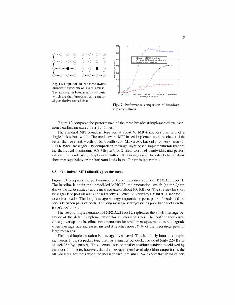
Figure 11 shows the principle of a 2D mesh broadcast. The message is cut into tworoughly equal pieces which are then routed over non-overlapping subsections of thetorus network. Any single torus link cannot be involved in routing more than one of thepieces of the broadcast, or else that link becomes a bottleneck.
19
Fig. 11. Depiction of 2D mesh-awarebroadcast algorithm on a 4 × 4 mesh.The message is broken into two partswhich are then broadcast using mutu-ally exclusive sets of links.
100 505 2553 12921 98113 2.5145e+06 9.6666e+070
50
100
150
200
250
300
350
Message size (Bytes)
Band
widt
h (M
Byte
s/s)
Standard MPICH2 broadcastOptimized MPI broadcast (dep. bits)Message layer broadcast
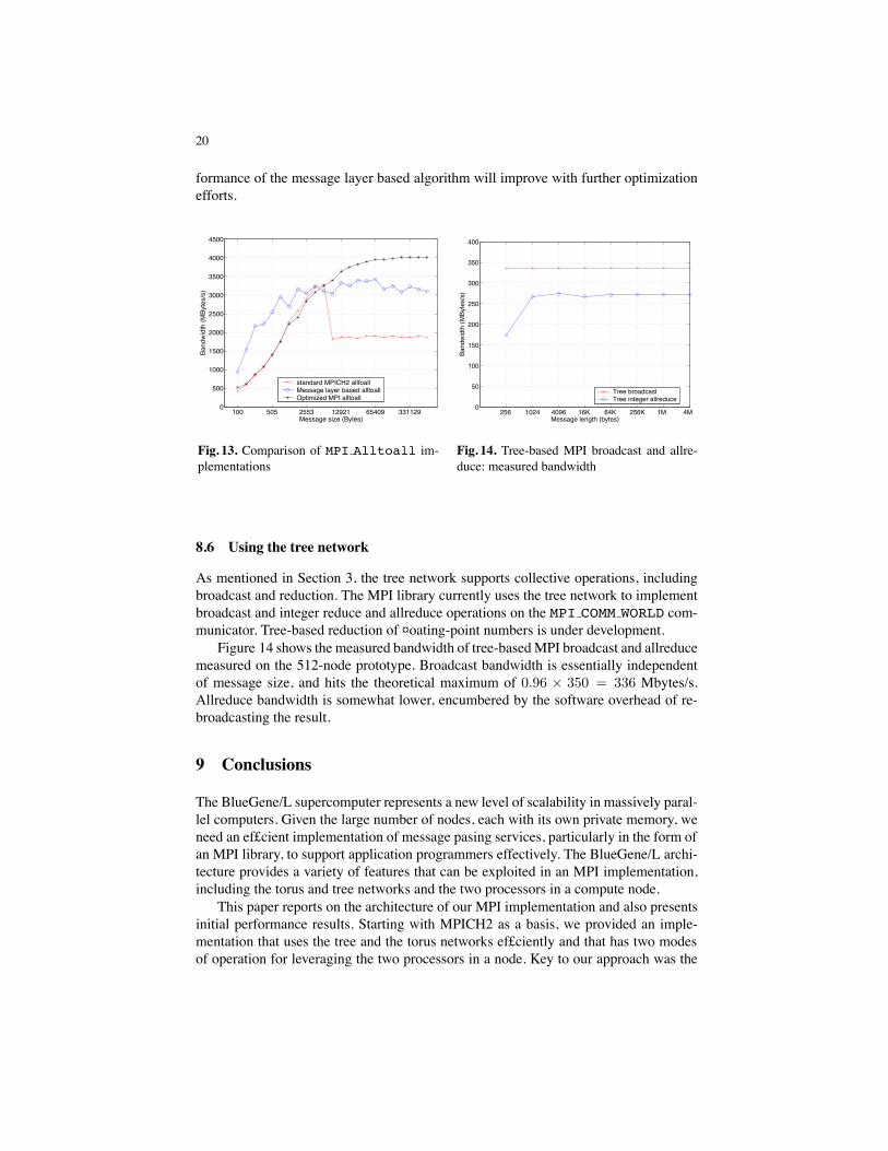
Fig. 12. Performance comparison of broadcastimplementations
Figure 12 compares the performance of the three broadcast implementations men-tioned earlier, measured on a 4 × 4 mesh.
The standard MPI broadcast tops out at about 60 MBytes/s, less than half of asingle link’s bandwidth. The mesh-aware MPI based implementation reaches a littlebetter than one link worth of bandwidth (200 MBytes/s), but only for very large (>200 KBytes) messages. By comparison message layer based implementation reachesthe theoretical maximum, 308 MBytes/s or 2 links worth of bandwidth, and perfor-mance climbs relatively steeply even with small message sizes. In order to better showshort message behavior the horizontal axis in this Figure is logarithmic.
8.5 Optimized MPI alltoall[v] on the torus
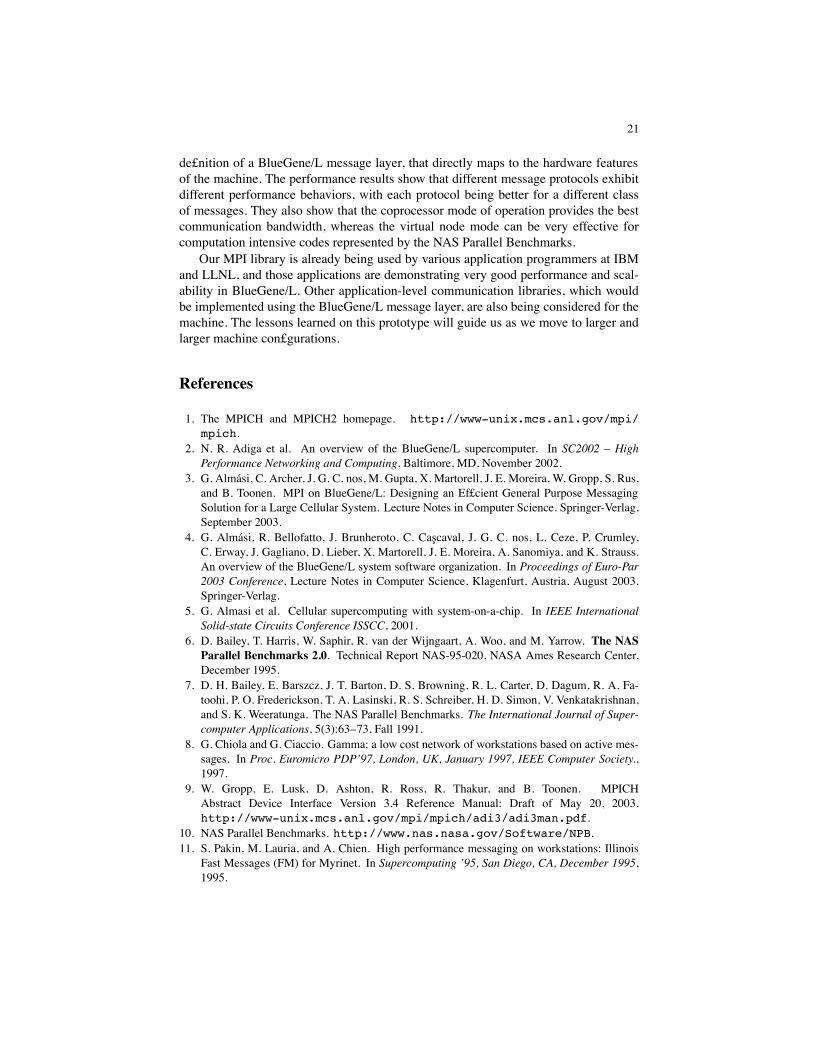
Figure 13 compares the performance of three implementations of MPI Alltoall.The baseline is again the unmodi£ed MPICH2 implementation, which (as the £gureshows) switches strategy at the message size of about 100 KBytes. The strategy for shortmessages is to post all sends and all receives at once, followed by a giant MPI Waitallto collect results. The long message strategy sequentially posts pairs of sends and re-ceives between pairs of hosts. The long message strategy yields poor bandwidth on theBlueGene/L torus.
The second implementation of MPI Alltoall replicates the small-message be-havior of the default implementation for all message sizes. The performance curveclosely overlaps the baseline implementation for small messages, but does not degradewhen message size increases: instead it reaches about 84% of the theoretical peak orlarge messages.
The third implementation is message layer based. This is a fairly immature imple-mentation. It uses a packet type that has a smaller per-packet payload (only 224 Bytesof each 256 Byte packet). This accounts for the smaller absolute bandwidth achieved bythe algorithm. Note, however, that the message layer-based algorithm outperforms theMPI-based algorithms when the message sizes are small. We expect that absolute per-
20
formance of the message layer based algorithm will improve with further optimizationefforts.
100 505 2553 12921 65409 3311290
500
1000
1500
2000
2500
3000
3500
4000
4500
Message size (Bytes)
Band
widt
h (M
Byte
s/s)
standard MPICH2 alltoallMessage layer based alltoallOptimized MPI alltoall
Fig. 13. Comparison of MPI Alltoall im-plementations
256 1024 4096 16K 64K 256K 1M 4M 0
50
100
150
200
250
300
350
400
Message length (bytes)
Band
widt
h (M
Byte
s/s)
Tree broadcastTree integer allreduce
Fig. 14. Tree-based MPI broadcast and allre-duce: measured bandwidth
8.6 Using the tree network
As mentioned in Section 3, the tree network supports collective operations, includingbroadcast and reduction. The MPI library currently uses the tree network to implementbroadcast and integer reduce and allreduce operations on the MPI COMM WORLD com-municator. Tree-based reduction of ¤oating-point numbers is under development.
Figure 14 shows the measured bandwidth of tree-basedMPI broadcast and allreducemeasured on the 512-node prototype. Broadcast bandwidth is essentially independentof message size, and hits the theoretical maximum of 0.96 × 350 = 336 Mbytes/s.Allreduce bandwidth is somewhat lower, encumbered by the software overhead of re-broadcasting the result.
9 Conclusions
The BlueGene/L supercomputer represents a new level of scalability in massively paral-lel computers. Given the large number of nodes, each with its own private memory, weneed an ef£cient implementation of message pasing services, particularly in the form ofan MPI library, to support application programmers effectively. The BlueGene/L archi-tecture provides a variety of features that can be exploited in an MPI implementation,including the torus and tree networks and the two processors in a compute node.
This paper reports on the architecture of our MPI implementation and also presentsinitial performance results. Starting with MPICH2 as a basis, we provided an imple-mentation that uses the tree and the torus networks ef£ciently and that has two modesof operation for leveraging the two processors in a node. Key to our approach was the
21
de£nition of a BlueGene/L message layer, that directly maps to the hardware featuresof the machine. The performance results show that different message protocols exhibitdifferent performance behaviors, with each protocol being better for a different classof messages. They also show that the coprocessor mode of operation provides the bestcommunication bandwidth, whereas the virtual node mode can be very effective forcomputation intensive codes represented by the NAS Parallel Benchmarks.
Our MPI library is already being used by various application programmers at IBMand LLNL, and those applications are demonstrating very good performance and scal-ability in BlueGene/L. Other application-level communication libraries, which wouldbe implemented using the BlueGene/L message layer, are also being considered for themachine. The lessons learned on this prototype will guide us as we move to larger andlarger machine con£gurations.
References
1. The MPICH and MPICH2 homepage. http://www-unix.mcs.anl.gov/mpi/mpich.
2. N. R. Adiga et al. An overview of the BlueGene/L supercomputer. In SC2002 – HighPerformance Networking and Computing, Baltimore, MD, November 2002.
3. G. Almasi, C. Archer, J. G. C. nos, M. Gupta, X. Martorell, J. E. Moreira, W. Gropp, S. Rus,and B. Toonen. MPI on BlueGene/L: Designing an Ef£cient General Purpose MessagingSolution for a Large Cellular System. Lecture Notes in Computer Science. Springer-Verlag,September 2003.
4. G. Almasi, R. Bellofatto, J. Brunheroto, C. Cascaval, J. G. C. nos, L. Ceze, P. Crumley,C. Erway, J. Gagliano, D. Lieber, X. Martorell, J. E. Moreira, A. Sanomiya, and K. Strauss.An overview of the BlueGene/L system software organization. In Proceedings of Euro-Par2003 Conference, Lecture Notes in Computer Science, Klagenfurt, Austria, August 2003.Springer-Verlag.
5. G. Almasi et al. Cellular supercomputing with system-on-a-chip. In IEEE InternationalSolid-state Circuits Conference ISSCC, 2001.
6. D. Bailey, T. Harris, W. Saphir, R. van der Wijngaart, A. Woo, and M. Yarrow. The NASParallel Benchmarks 2.0. Technical Report NAS-95-020, NASA Ames Research Center,December 1995.
7. D. H. Bailey, E. Barszcz, J. T. Barton, D. S. Browning, R. L. Carter, D. Dagum, R. A. Fa-toohi, P. O. Frederickson, T. A. Lasinski, R. S. Schreiber, H. D. Simon, V. Venkatakrishnan,and S. K. Weeratunga. The NAS Parallel Benchmarks. The International Journal of Super-computer Applications, 5(3):63–73, Fall 1991.
8. G. Chiola and G. Ciaccio. Gamma: a low cost network of workstations based on active mes-sages. In Proc. Euromicro PDP’97, London, UK, January 1997, IEEE Computer Society.,1997.
9. W. Gropp, E. Lusk, D. Ashton, R. Ross, R. Thakur, and B. Toonen. MPICHAbstract Device Interface Version 3.4 Reference Manual: Draft of May 20, 2003.http://www-unix.mcs.anl.gov/mpi/mpich/adi3/adi3man.pdf.
10. NAS Parallel Benchmarks. http://www.nas.nasa.gov/Software/NPB.11. S. Pakin, M. Lauria, and A. Chien. High performance messaging on workstations: Illinois
Fast Messages (FM) for Myrinet. In Supercomputing ’95, San Diego, CA, December 1995,1995.
22
12. M. Snir, S. Otto, S. Huss-Lederman, D. Walker, and J. Dongarra. MPI - The CompleteReference, second edition. The MIT Press, 2000.
13. D. Turner, A. Oline, X. Chen, and T. Benjegerdes. Integrating new capabilities into NetPIPE.Lecture Notes in Computer Science. Springer-Verlag, September 2003.
14. T. von Eicken, A. Basu, V. Buch, and W. Vogels. U-net: A user-level network interfacefor parallel and distributed computing. In Proceedings of the 15th ACM Symposium onOperating Systems Principles, Copper Mountain, Colorado, December 1995.
15. T. von Eicken, D. E. Culler, S. C. Goldstein, and K. E. Schauser. Active Messages: a mech-anism for integrated communication and computation. In Proceedings of the 19th Interna-tional Symposium on Computer Architecture, May 1992.