T-A & GEN2 T-A Thread MillingHigh Performance Threading Solutions AMEC’s thread milling programme...
30
T-A & GEN2 T-A GEN3SYS APX Revolution & Core Drill ASC 320 Solid Carbide AccuPort 432 Criterion Thread Milling Special Tooling +44 (0)1384 400 900 +44 (0)1384 400 105 [email protected] www.alliedmaxcut.com 261 CONTENTS Thread Milling Range Page 262 How to Identify Information Page 264 MaxThread Thread Mills (BSPP/BSPT/BSW) Page 265 MaxThread Thread Mills (NPT/NPTF) Page 266 MaxThread Thread Mills (UN) Page 267 MaxThread Thread Mills (Metric) Page 268 MaxThread Thread Mills - Technical Section Page 269 AccuThread Thread Mills (BSPP/BSPT/BSW) Page 270 AccuThread Thread Mills (NPT/NPTF/AccuPort) Page 271 AccuThread Thread Mills (UN) Page 272 AccuThread Thread Mills (Metric & made to order) Page 273 AccuThread Bolt in Style Inserts (UN) Page 274 AccuThread Bolt in Style Inserts (UNJ) Page 275 AccuThread Bolt in Style Inserts (Metric/BSPP) Page 276 AccuThread Bolt in Style Holder (UN/ISO/BSPP) Page 276 AccuThread Bolt in Style Inserts (BSPT/NPT/NPTF) Page 277 AccuThread Bolt in Style Holder (NPT/NPTF/BSPT) Page 277 AccuThread Pin Style Inserts (NPT/NPTF/BSPP/BSPT/API) Page 278 AccuThread Pin Style Inserts (UN) Page 279 AccuThread Pin Style Inserts (UNJ) Page 280 AccuThread Pin Style Inserts (Metric/ACME) Page 281 AccuThread Pin Style Holders Page 282 AccuThread Technical Section Page 283 Guaranteed Application Request Form Page 301 • Complete programme available of both solid carbide and indexable thread mills • All tools can produce left or right hand threads • Full profiles present on all inserts and solid carbide thread mills • High technology manufacturing ensures consistent thread forms Features and Benefits The MaxThread TM and the AccuThread 856 ® threadmill ranges are designed to deliver outstanding performance, long tool life and high precision, whether using our solid carbide or indexable insert threadmills. Thread Milling
Transcript of T-A & GEN2 T-A Thread MillingHigh Performance Threading Solutions AMEC’s thread milling programme...
T-A
& GE
N2 T-
AGE
N3SY
SAP
XRe
volut
ion &
Cor
e Dril
lAS
C 32
0 So
lid C
arbid
eAc
cuPo
rt 43
2Cr
iterio
nTh
read
Milli
ngSp
ecial
Tooli
ng
+44 (0)1384 400 900 +44 (0)1384 400 105 [email protected] www.alliedmaxcut.com +44 (0)1384 400 900 +44 (0)1384 400 105 [email protected] www.alliedmaxcut.com261
CONTENTS
Thread Milling Range Page 262
How to Identify Information Page 264
MaxThread Thread Mills (BSPP/BSPT/BSW) Page 265
MaxThread Thread Mills (NPT/NPTF) Page 266
MaxThread Thread Mills (UN) Page 267
MaxThread Thread Mills (Metric) Page 268
MaxThread Thread Mills - Technical Section Page 269
AccuThread Thread Mills (BSPP/BSPT/BSW) Page 270
AccuThread Thread Mills (NPT/NPTF/AccuPort) Page 271
AccuThread Thread Mills (UN) Page 272
AccuThread Thread Mills (Metric & made to order) Page 273
AccuThread Bolt in Style Inserts (UN) Page 274
AccuThread Bolt in Style Inserts (UNJ) Page 275
AccuThread Bolt in Style Inserts (Metric/BSPP) Page 276
AccuThread Bolt in Style Holder (UN/ISO/BSPP) Page 276
AccuThread Bolt in Style Inserts (BSPT/NPT/NPTF) Page 277
AccuThread Bolt in Style Holder (NPT/NPTF/BSPT) Page 277
AccuThread Pin Style Inserts(NPT/NPTF/BSPP/BSPT/API) Page 278
AccuThread Pin Style Inserts (UN) Page 279
AccuThread Pin Style Inserts (UNJ) Page 280
AccuThread Pin Style Inserts (Metric/ACME) Page 281
AccuThread Pin Style Holders Page 282
AccuThread Technical Section Page 283
Guaranteed Application Request Form Page 301
• Complete programme available of both solid carbide and indexable thread mills
• All tools can produce left or right hand threads
• Full profiles present on all inserts and solid carbide thread mills
• High technology manufacturing ensures consistent thread forms
Features and Benefits
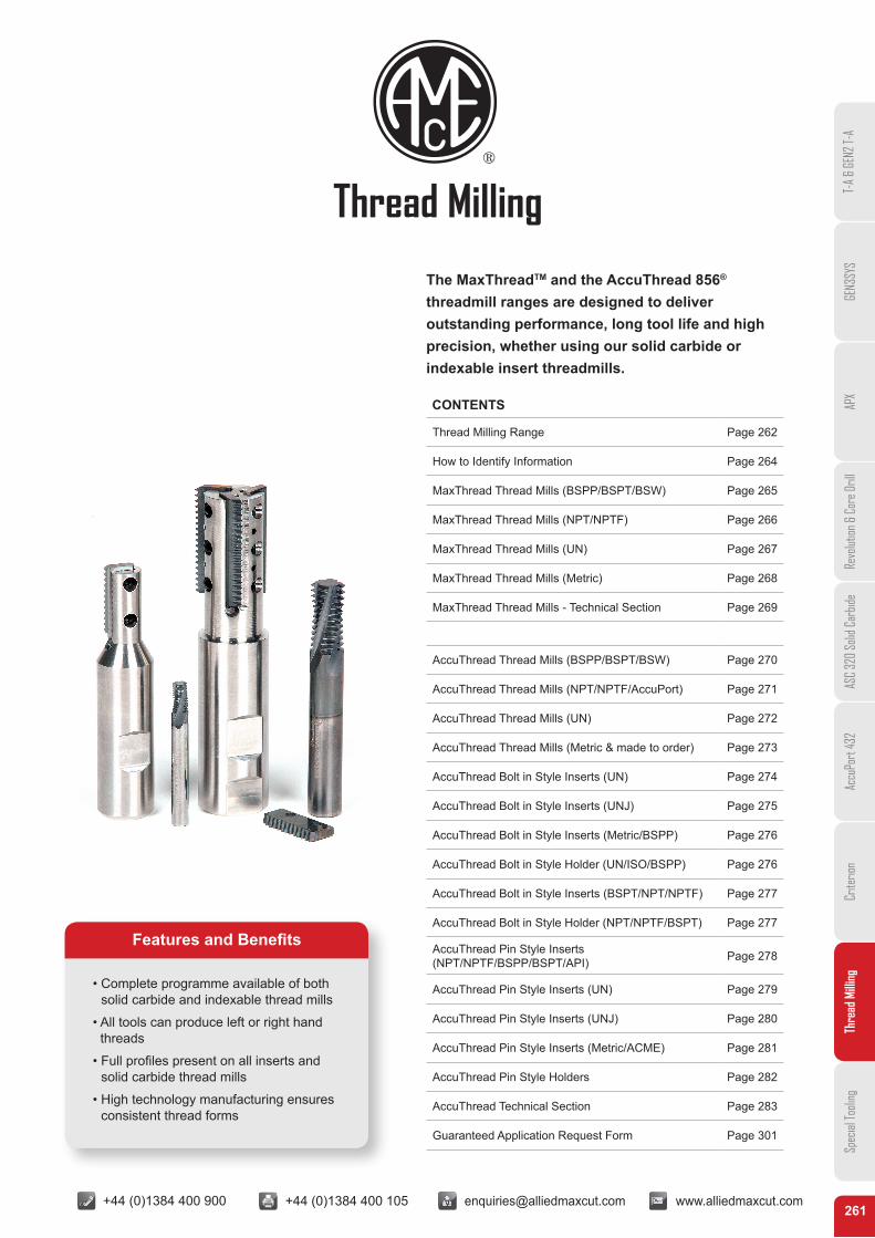
The MaxThreadTM and the AccuThread 856® threadmill ranges are designed to deliver outstanding performance, long tool life and high precision, whether using our solid carbide or indexable insert threadmills.
Thread Milling
T-A
& GE
N2 T-
AGE
N3SY
SAP
XRe
volut
ion &
Cor
e Dril
lAS
C 32
0 So
lid C
arbid
eAc
cuPo
rt 43
2Cr
iterio
nTh
read
Milli
ngSp
ecial
Tooli
ng
+44 (0)1384 400 900 +44 (0)1384 400 105 [email protected] www.alliedmaxcut.com +44 (0)1384 400 900 +44 (0)1384 400 105 [email protected] www.alliedmaxcut.com262
Thread Milling
High Performance Threading Solutions
AMEC’s thread milling programme has developed into a comprehensive range of high precision tooling offering outstanding productivity with exceptional levels of tool life and thread accuracy. The thread mill range covers both solid carbide and indexable replaceable insert tools with an extensive range of threads forms.
Our thread milling programme has been specifically designed to provide customers with a wide choice. This is achieved by offering two thread mill ranges within our product line up – the low cost, general purpose MaxThreadTM thread mill range and the high performance, high productivity AccuThread 856® range.
Both product ranges are designed for manufacturing and production environments and offer excellent performance and thread accuracy, allowing AMEC® to offer the best product for the job, to help give our customers the cutting edge.
Also available is AMEC’s ‘Special Products’, solutions that provide engineers, designers and production managers with the opportunity of creating application specific tooling that can achieve levels of efficiency and performance beyond standard threading solutions.
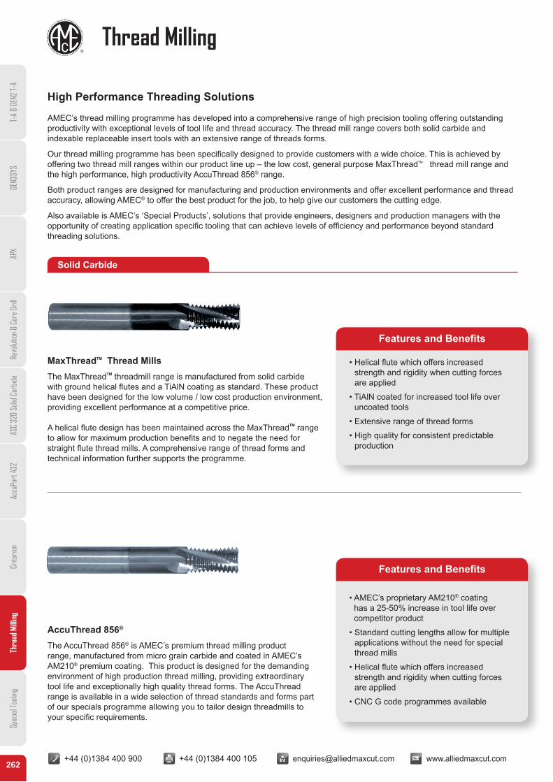
MaxThreadTM Thread MillsThe MaxThreadTM threadmill range is manufactured from solid carbide with ground helical flutes and a TiAlN coating as standard. These product have been designed for the low volume / low cost production environment, providing excellent performance at a competitive price.
A helical flute design has been maintained across the MaxThreadTM range to allow for maximum production benefits and to negate the need for straight flute thread mills. A comprehensive range of thread forms and technical information further supports the programme.
AccuThread 856®
The AccuThread 856® is AMEC’s premium thread milling product range, manufactured from micro grain carbide and coated in AMEC’s AM210® premium coating. This product is designed for the demanding environment of high production thread milling, providing extraordinary tool life and exceptionally high quality thread forms. The AccuThread range is available in a wide selection of thread standards and forms part of our specials programme allowing you to tailor design threadmills to your specific requirements.
• Helical flute which offers increased strength and rigidity when cutting forces are applied
• TiAlN coated for increased tool life over uncoated tools
• Extensive range of thread forms
• High quality for consistent predictable production
• AMEC’s proprietary AM210® coating has a 25-50% increase in tool life over competitor product
• Standard cutting lengths allow for multiple applications without the need for special thread mills
• Helical flute which offers increased strength and rigidity when cutting forces are applied
• CNC G code programmes available
Features and Benefits
Features and Benefits
Solid Carbide
T-A
& GE
N2 T-
AGE
N3SY
SAP
XRe
volut
ion &
Cor
e Dril
lAS
C 32
0 So
lid C
arbid
eAc
cuPo
rt 43
2Cr
iterio
nTh
read
Milli
ngSp
ecial
Tooli
ng
+44 (0)1384 400 900 +44 (0)1384 400 105 [email protected] www.alliedmaxcut.com +44 (0)1384 400 900 +44 (0)1384 400 105 [email protected] www.alliedmaxcut.com263
Thread Milling
Indexable Thread Milling
• Thread mill holders are manufactured from stainless steel that is engineered to dampen vibration during operation
• Extensive range of thread forms with two thread lengths
• Can produce left or right handed threads
• Full profiles present on all inserts allows 100% thread form against 65-75% for tapping
• AMEC’s proprietary AM210® coating has a 25-50% increase in tool life over competitor product
• AMEC’s premium carbide allows for extended tool life whilst providing high quality thread forms
• Patented pin style locking system ensures unsurpassed repeatability
• Thread mill holders are manufactured from stainless steel that is engineered to dampen vibration during operation
• Extensive range of thread forms with two thread lengths
Features and Benefits
Features and Benefits
Features and Benefits
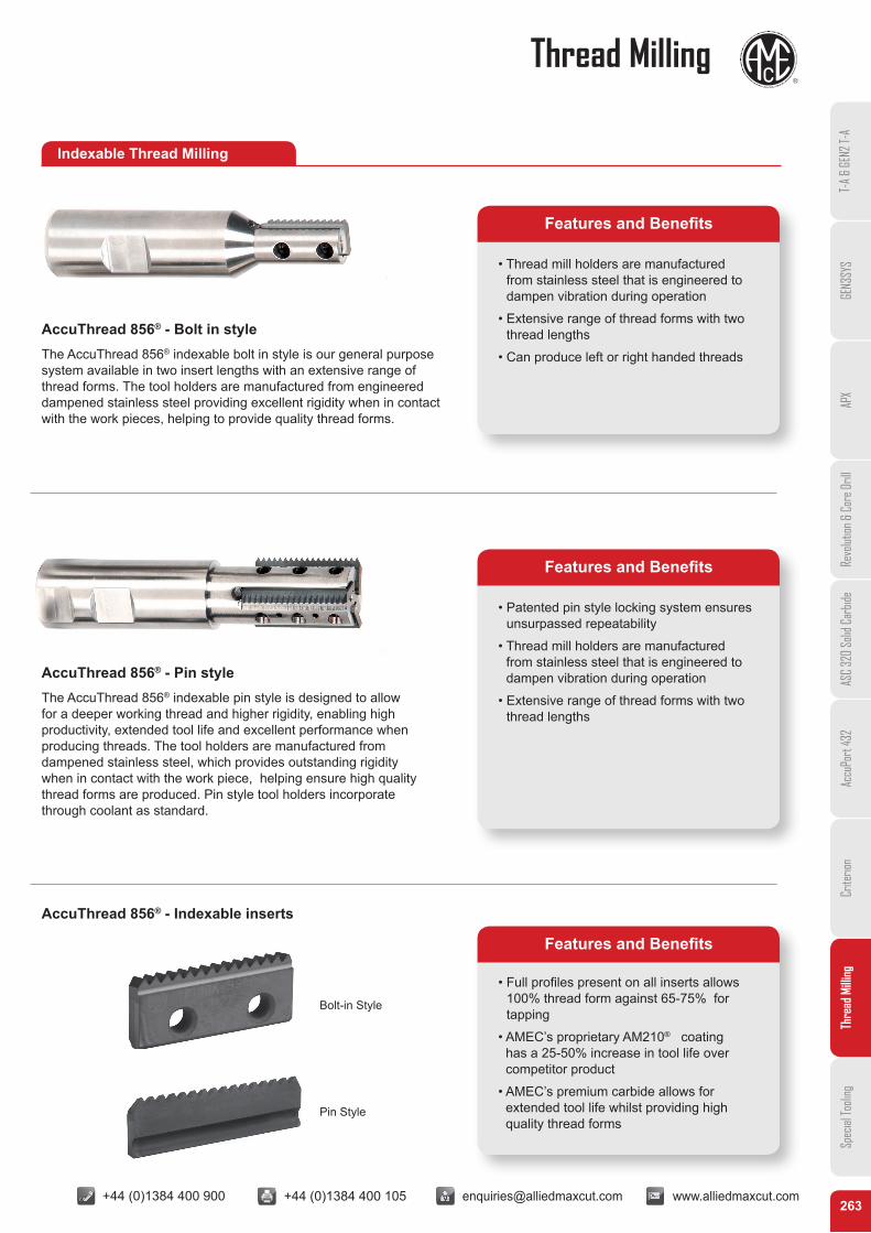
AccuThread 856® - Bolt in styleThe AccuThread 856® indexable bolt in style is our general purpose system available in two insert lengths with an extensive range of thread forms. The tool holders are manufactured from engineered dampened stainless steel providing excellent rigidity when in contact with the work pieces, helping to provide quality thread forms.
AccuThread 856® - Pin styleThe AccuThread 856® indexable pin style is designed to allow for a deeper working thread and higher rigidity, enabling high productivity, extended tool life and excellent performance when producing threads. The tool holders are manufactured from dampened stainless steel, which provides outstanding rigidity when in contact with the work piece, helping ensure high quality thread forms are produced. Pin style tool holders incorporate through coolant as standard.
AccuThread 856® - Indexable inserts
Bolt-in Style
Pin Style
+44 (0)1384 400 900 +44 (0)1384 400 105 [email protected] www.alliedmaxcut.com +44 (0)1384 400 900 +44 (0)1384 400 105 [email protected] www.alliedmaxcut.com264
How to Identify InformationT-
A &
GEN2
T-A
GEN3
SYS
APX
Revo
lution
& C
ore D
rill
ASC
320
Solid
Car
bide
Accu
Port
432
Crite
rion
Thre
ad M
illing
Spec
ial To
oling
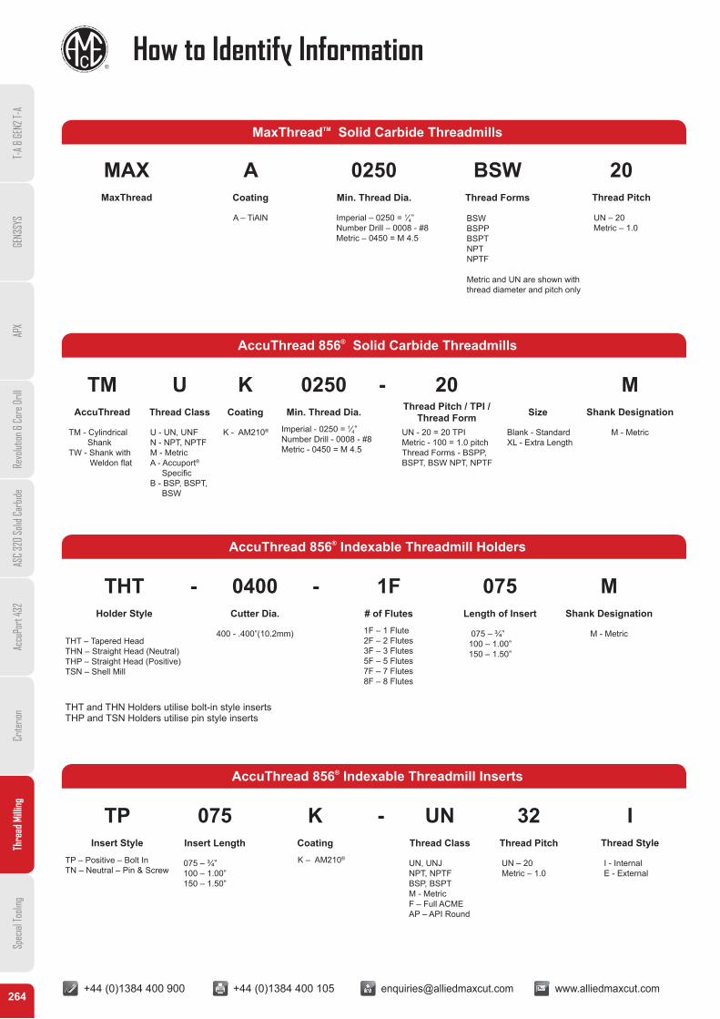
MaxThreadTM Solid Carbide Threadmills
MAX A 0250 BSW 20MaxThread Coating Min. Thread Dia. Thread Forms Thread Pitch
A – TiAlN Imperial – 0250 = 1⁄4” Number Drill – 0008 - #8Metric – 0450 = M 4.5
BSW BSPP BSPT NPT NPTF
UN – 20Metric – 1.0
Metric and UN are shown with thread diameter and pitch only
AccuThread 856® Solid Carbide Threadmills
TM U K 0250 - 20 MAccuThread Thread Class Coating Min. Thread Dia. Thread Pitch / TPI /
Thread Form Size Shank Designation
TM - Cylindrical ShankTW - Shank with Weldon flat
U - UN, UNFN - NPT, NPTFM - MetricA - Accuport® SpecificB - BSP, BSPT, BSW
K - AM210® Imperial - 0250 = 1⁄4” Number Drill - 0008 - #8Metric - 0450 = M 4.5
UN - 20 = 20 TPIMetric - 100 = 1.0 pitchThread Forms - BSPP,BSPT, BSW NPT, NPTF
Blank - StandardXL - Extra Length
M - Metric
AccuThread 856® Indexable Threadmill Inserts
TP 075 K - UN 32 IInsert Style Insert Length Coating Thread Class Thread Pitch Thread Style
TP – Positive – Bolt InTN – Neutral – Pin & Screw
075 – ¾”100 – 1.00”150 – 1.50”
K – AM210® UN, UNJNPT, NPTFBSP, BSPTM - MetricF – Full ACME AP – API Round
UN – 20Metric – 1.0
I - InternalE - External
AccuThread 856® Indexable Threadmill Holders
THT - 0400 - 1F 075 MHolder Style Cutter Dia. # of Flutes Length of Insert Shank Designation
THT – Tapered HeadTHN – Straight Head (Neutral) THP – Straight Head (Positive) TSN – Shell Mill
400 - .400”(10.2mm) 1F – 1 Flute 2F – 2 Flutes 3F – 3 Flutes 5F – 5 Flutes 7F – 7 Flutes 8F – 8 Flutes
075 – ¾”100 – 1.00”150 – 1.50”
M - Metric
THT and THN Holders utilise bolt-in style inserts THP and TSN Holders utilise pin style inserts
+44 (0)1384 400 900 +44 (0)1384 400 105 [email protected] www.alliedmaxcut.com +44 (0)1384 400 900 +44 (0)1384 400 105 [email protected] www.alliedmaxcut.com265
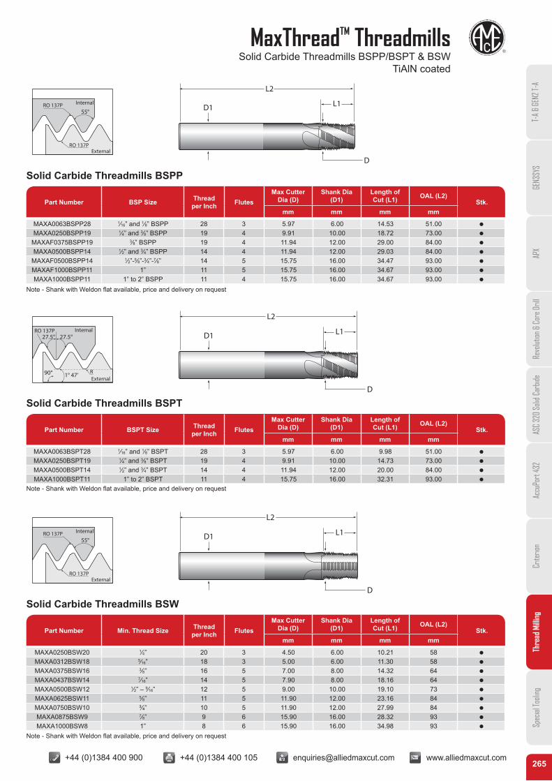
MaxThreadTM ThreadmillsSolid Carbide Threadmills BSPP/BSPT & BSW
TiAlN coated
T-A
& GE
N2 T-
AGE
N3SY
SAP
XRe
volut
ion &
Cor
e Dril
lAS
C 32
0 So
lid C
arbid
eAc
cuPo
rt 43
2Cr
iterio
nTh
read
Milli
ngSp
ecial
Tooli
ng
55°
External
InternalRO 137P
RO 137P
55°
External
InternalRO 137P
RO 137P
90°
27.5°27.5°RO 137P
R1° 47’
Internal
External
D1
L2
L1
D
D1
L2
L1
D
D1
L2
L1
D
Solid Carbide Threadmills BSPP
Solid Carbide Threadmills BSW
Solid Carbide Threadmills BSPT
Part Number BSP Size Thread per Inch Flutes
Max Cutter Dia (D)
Shank Dia (D1)
Length of Cut (L1) OAL (L2)
Stk.mm mm mm mm
Part Number Min. Thread Size Thread per Inch Flutes
Max Cutter Dia (D)
Shank Dia (D1)
Length of Cut (L1) OAL (L2)
Stk.mm mm mm mm
Part Number BSPT Size Thread per Inch Flutes
Max Cutter Dia (D)
Shank Dia (D1)
Length of Cut (L1) OAL (L2)
Stk.mm mm mm mm
MAXA0063BSPP28 1⁄16” and 1⁄8” BSPP 28 3 5.97 6.00 14.53 51.00 Q
MAXA0250BSPP19 1⁄4” and 3⁄8” BSPP 19 4 9.91 10.00 18.72 73.00 Q
MAXAF0375BSPP19 3⁄8” BSPP 19 4 11.94 12.00 29.00 84.00 Q
MAXA0500BSPP14 1⁄2” and 3⁄4” BSPP 14 4 11.94 12.00 29.03 84.00 Q
MAXAF0500BSPP14 1⁄2”-5⁄8”-3⁄4”-7⁄8” 14 5 15.75 16.00 34.47 93.00 Q
MAXAF1000BSPP11 1” 11 5 15.75 16.00 34.67 93.00 Q
MAXA1000BSPP11 1” to 2” BSPP 11 4 15.75 16.00 34.67 93.00 Q
MAXA0250BSW20 1⁄4” 20 3 4.50 6.00 10.21 58 Q
MAXA0312BSW18 5⁄16” 18 3 5.00 6.00 11.30 58 Q
MAXA0375BSW16 3⁄8” 16 5 7.00 8.00 14.32 64 Q
MAXA0437BSW14 7⁄16” 14 5 7.90 8.00 18.16 64 Q
MAXA0500BSW12 1⁄2” – 9⁄16” 12 5 9.00 10.00 19.10 73 Q
MAXA0625BSW11 5⁄8” 11 5 11.90 12.00 23.16 84 Q
MAXA0750BSW10 ¾” 10 5 11.90 12.00 27.99 84 Q
MAXA0875BSW9 7⁄8” 9 6 15.90 16.00 28.32 93 Q
MAXA1000BSW8 1” 8 6 15.90 16.00 34.98 93 Q
MAXA0063BSPT28 1⁄16” and 1⁄8” BSPT 28 3 5.97 6.00 9.98 51.00 Q
MAXA0250BSPT19 1⁄4” and 3⁄8” BSPT 19 4 9.91 10.00 14.73 73.00 Q
MAXA0500BSPT14 1⁄2” and 3⁄4” BSPT 14 4 11.94 12.00 20.00 84.00 Q
MAXA1000BSPT11 1” to 2” BSPT 11 4 15.75 16.00 32.31 93.00 Q
Note - Shank with Weldon flat available, price and delivery on request
Note - Shank with Weldon flat available, price and delivery on request
Note - Shank with Weldon flat available, price and delivery on request
+44 (0)1384 400 900 +44 (0)1384 400 105 [email protected] www.alliedmaxcut.com +44 (0)1384 400 900 +44 (0)1384 400 105 [email protected] www.alliedmaxcut.com266
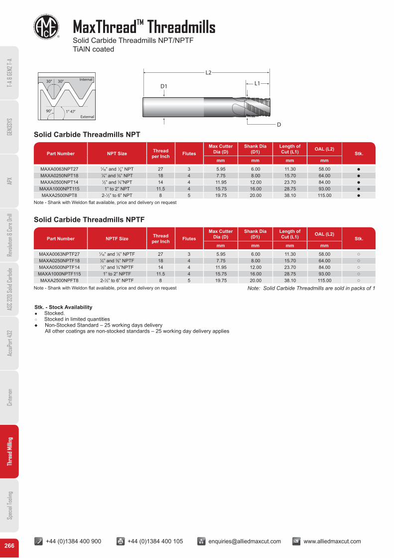
MaxThreadTM ThreadmillsSolid Carbide Threadmills NPT/NPTFTiAlN coated
T-A
& GE
N2 T-
AGE
N3SY
SAP
XRe
volut
ion &
Cor
e Dril
lAS
C 32
0 So
lid C
arbid
eAc
cuPo
rt 43
2Cr
iterio
nTh
read
Milli
ngSp
ecial
Tooli
ng
90° 1° 47’
30° 30°
External
Internal
D1
L2
L1
D
Solid Carbide Threadmills NPT
Solid Carbide Threadmills NPTF
Part Number NPT Size Thread per Inch Flutes
Max Cutter Dia (D)
Shank Dia (D1)
Length of Cut (L1) OAL (L2)
Stk.mm mm mm mm
Part Number NPTF Size Thread per Inch Flutes
Max Cutter Dia (D)
Shank Dia (D1)
Length of Cut (L1) OAL (L2)
Stk.mm mm mm mm
MAXA0063NPT27 1⁄16” and 1⁄8” NPT 27 3 5.95 6.00 11.30 58.00 Q
MAXA0250NPT18 1⁄4” and 3⁄8” NPT 18 4 7.75 8.00 15.70 64.00 Q
MAXA0500NPT14 1⁄2” and 3⁄4”NPT 14 4 11.95 12.00 23.70 84.00 Q
MAXA1000NPT115 1” to 2” NPT 11.5 4 15.75 16.00 28.75 93.00 Q
MAXA2500NPT8 2-1⁄2” to 6” NPT 8 5 19.75 20.00 38.10 115.00 Q
MAXA0063NPTF27 1⁄16” and 1⁄8” NPTF 27 3 5.95 6.00 11.30 58.00 p
MAXA0250NPTF18 1⁄4” and 3⁄8” NPTF 18 4 7.75 8.00 15.70 64.00 p
MAXA0500NPTF14 1⁄2” and 3⁄4”NPTF 14 4 11.95 12.00 23.70 84.00 p
MAXA1000NPTF115 1” to 2” NPTF 11.5 4 15.75 16.00 28.75 93.00 p
MAXA2500NPFT8 2-1⁄2” to 6” NPTF 8 5 19.75 20.00 38.10 115.00 p
Note: Solid Carbide Threadmills are sold in packs of 1
Stk. - Stock Availability Q Stocked. q Stocked in limited quantitiesu Non-Stocked Standard – 25 working days delivery
All other coatings are non-stocked standards – 25 working day delivery applies
Note - Shank with Weldon flat available, price and delivery on request
Note - Shank with Weldon flat available, price and delivery on request
+44 (0)1384 400 900 +44 (0)1384 400 105 [email protected] www.alliedmaxcut.com +44 (0)1384 400 900 +44 (0)1384 400 105 [email protected] www.alliedmaxcut.com267
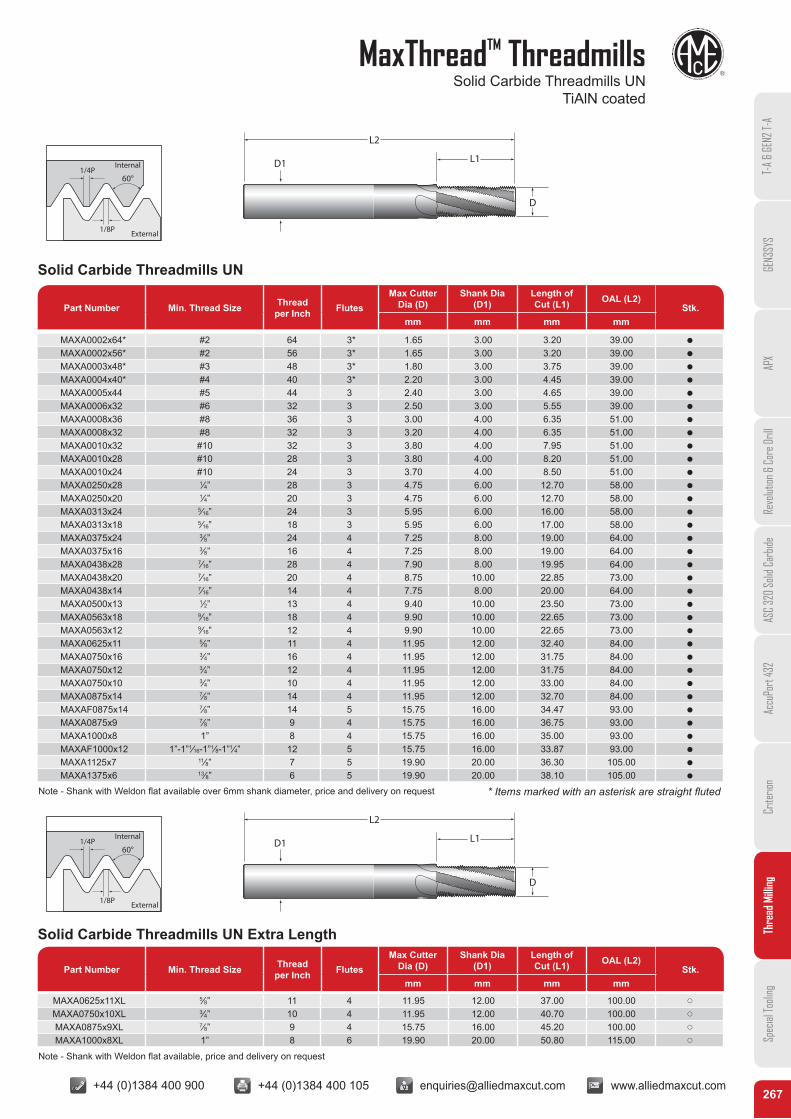
MaxThreadTM ThreadmillsSolid Carbide Threadmills UN
TiAlN coated
T-A
& GE
N2 T-
AGE
N3SY
SAP
XRe
volut
ion &
Cor
e Dril
lAS
C 32
0 So
lid C
arbid
eAc
cuPo
rt 43
2Cr
iterio
nTh
read
Milli
ngSp
ecial
Tooli
ng
60°1/4P
1/8P
Internal
External
60°1/4P
1/8P
Internal
External
D1
L2
L1
D
D1
L2
L1
D
Solid Carbide Threadmills UN
Part Number Min. Thread Size Thread per Inch Flutes
Max Cutter Dia (D)
Shank Dia (D1)
Length of Cut (L1) OAL (L2)
Stk.mm mm mm mm
MAXA0002x64* #2 64 3* 1.65 3.00 3.20 39.00 Q
MAXA0002x56* #2 56 3* 1.65 3.00 3.20 39.00 Q
MAXA0003x48* #3 48 3* 1.80 3.00 3.75 39.00 Q
MAXA0004x40* #4 40 3* 2.20 3.00 4.45 39.00 Q
MAXA0005x44 #5 44 3 2.40 3.00 4.65 39.00 Q
MAXA0006x32 #6 32 3 2.50 3.00 5.55 39.00 Q
MAXA0008x36 #8 36 3 3.00 4.00 6.35 51.00 Q
MAXA0008x32 #8 32 3 3.20 4.00 6.35 51.00 Q
MAXA0010x32 #10 32 3 3.80 4.00 7.95 51.00 Q
MAXA0010x28 #10 28 3 3.80 4.00 8.20 51.00 Q
MAXA0010x24 #10 24 3 3.70 4.00 8.50 51.00 Q
MAXA0250x28 1⁄4” 28 3 4.75 6.00 12.70 58.00 Q
MAXA0250x20 1⁄4” 20 3 4.75 6.00 12.70 58.00 Q
MAXA0313x24 5⁄16” 24 3 5.95 6.00 16.00 58.00 Q
MAXA0313x18 5⁄16” 18 3 5.95 6.00 17.00 58.00 Q
MAXA0375x24 3⁄8” 24 4 7.25 8.00 19.00 64.00 Q
MAXA0375x16 3⁄8” 16 4 7.25 8.00 19.00 64.00 Q
MAXA0438x28 7⁄16” 28 4 7.90 8.00 19.95 64.00 Q
MAXA0438x20 7⁄16” 20 4 8.75 10.00 22.85 73.00 Q
MAXA0438x14 7⁄16” 14 4 7.75 8.00 20.00 64.00 Q
MAXA0500x13 1⁄2” 13 4 9.40 10.00 23.50 73.00 Q
MAXA0563x18 9⁄16” 18 4 9.90 10.00 22.65 73.00 Q
MAXA0563x12 9⁄16” 12 4 9.90 10.00 22.65 73.00 Q
MAXA0625x11 5⁄8” 11 4 11.95 12.00 32.40 84.00 Q
MAXA0750x16 3⁄4” 16 4 11.95 12.00 31.75 84.00 Q
MAXA0750x12 3⁄4” 12 4 11.95 12.00 31.75 84.00 Q
MAXA0750x10 3⁄4” 10 4 11.95 12.00 33.00 84.00 Q
MAXA0875x14 7⁄8” 14 4 11.95 12.00 32.70 84.00 Q
MAXAF0875x14 7⁄8” 14 5 15.75 16.00 34.47 93.00 Q
MAXA0875x9 7⁄8” 9 4 15.75 16.00 36.75 93.00 Q
MAXA1000x8 1” 8 4 15.75 16.00 35.00 93.00 Q
MAXAF1000x12 1”-1”1⁄16-1”1⁄8-1”1⁄4” 12 5 15.75 16.00 33.87 93.00 Q
MAXA1125x7 11⁄8” 7 5 19.90 20.00 36.30 105.00 Q
MAXA1375x6 13⁄8” 6 5 19.90 20.00 38.10 105.00 Q
Solid Carbide Threadmills UN Extra Length
Part Number Min. Thread Size Thread per Inch Flutes
Max Cutter Dia (D)
Shank Dia (D1)
Length of Cut (L1) OAL (L2)
Stk.mm mm mm mm
MAXA0625x11XL 5⁄8” 11 4 11.95 12.00 37.00 100.00 p
MAXA0750x10XL 3⁄4” 10 4 11.95 12.00 40.70 100.00 p
MAXA0875x9XL 7⁄8” 9 4 15.75 16.00 45.20 100.00 p
MAXA1000x8XL 1” 8 6 19.90 20.00 50.80 115.00 p
* Items marked with an asterisk are straight flutedNote - Shank with Weldon flat available over 6mm shank diameter, price and delivery on request
Note - Shank with Weldon flat available, price and delivery on request
+44 (0)1384 400 900 +44 (0)1384 400 105 [email protected] www.alliedmaxcut.com +44 (0)1384 400 900 +44 (0)1384 400 105 [email protected] www.alliedmaxcut.com268
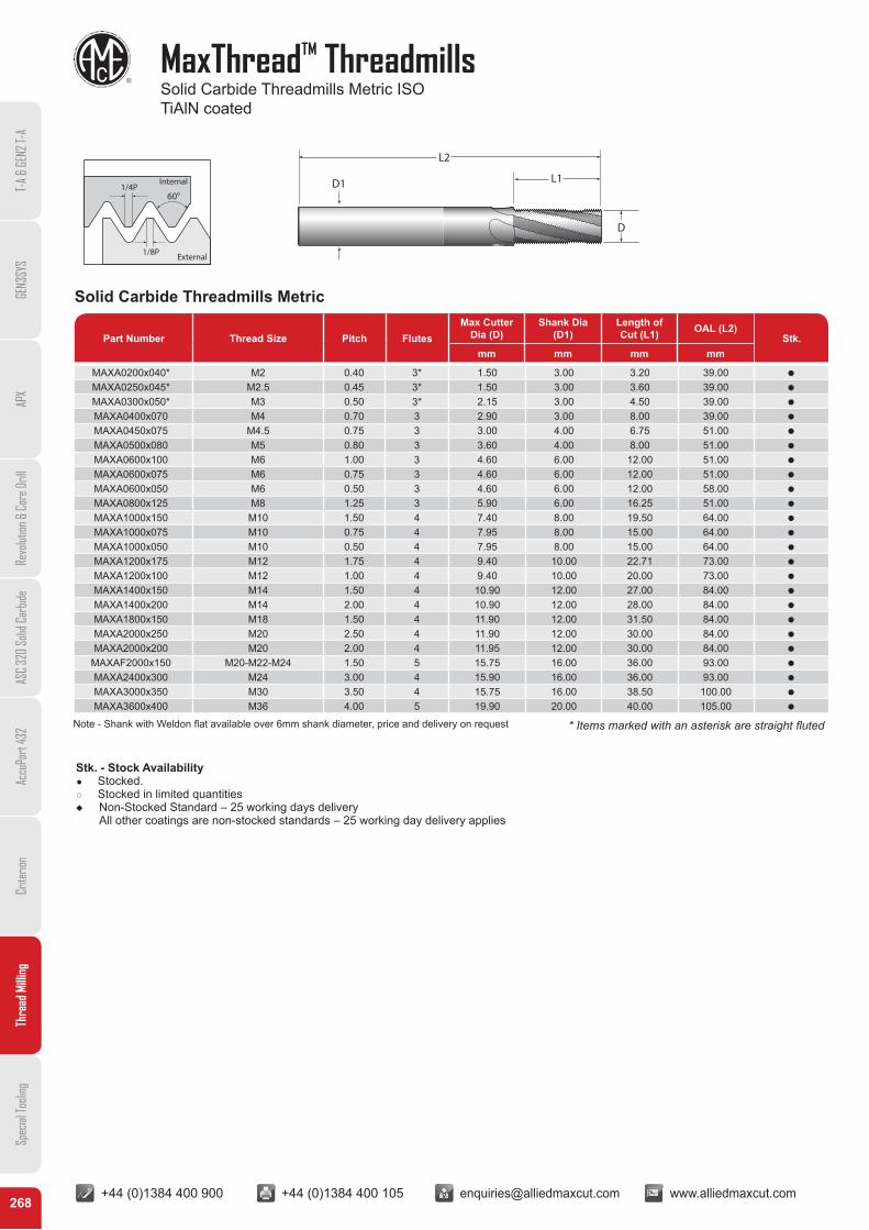
MaxThreadTM ThreadmillsSolid Carbide Threadmills Metric ISO TiAlN coated
T-A
& GE
N2 T-
AGE
N3SY
SAP
XRe
volut
ion &
Cor
e Dril
lAS
C 32
0 So
lid C
arbid
eAc
cuPo
rt 43
2Cr
iterio
nTh
read
Milli
ngSp
ecial
Tooli
ng
60°1/4P
1/8P
Internal
External
D1
L2
L1
D
Solid Carbide Threadmills Metric
Part Number Thread Size Pitch FlutesMax Cutter
Dia (D)Shank Dia
(D1)Length of Cut (L1) OAL (L2)
Stk.mm mm mm mm
MAXA0200x040* M2 0.40 3* 1.50 3.00 3.20 39.00 Q
MAXA0250x045* M2.5 0.45 3* 1.50 3.00 3.60 39.00 Q
MAXA0300x050* M3 0.50 3* 2.15 3.00 4.50 39.00 Q
MAXA0400x070 M4 0.70 3 2.90 3.00 8.00 39.00 Q
MAXA0450x075 M4.5 0.75 3 3.00 4.00 6.75 51.00 Q
MAXA0500x080 M5 0.80 3 3.60 4.00 8.00 51.00 Q
MAXA0600x100 M6 1.00 3 4.60 6.00 12.00 51.00 Q
MAXA0600x075 M6 0.75 3 4.60 6.00 12.00 51.00 Q
MAXA0600x050 M6 0.50 3 4.60 6.00 12.00 58.00 Q
MAXA0800x125 M8 1.25 3 5.90 6.00 16.25 51.00 Q
MAXA1000x150 M10 1.50 4 7.40 8.00 19.50 64.00 Q
MAXA1000x075 M10 0.75 4 7.95 8.00 15.00 64.00 Q
MAXA1000x050 M10 0.50 4 7.95 8.00 15.00 64.00 Q
MAXA1200x175 M12 1.75 4 9.40 10.00 22.71 73.00 Q
MAXA1200x100 M12 1.00 4 9.40 10.00 20.00 73.00 Q
MAXA1400x150 M14 1.50 4 10.90 12.00 27.00 84.00 Q
MAXA1400x200 M14 2.00 4 10.90 12.00 28.00 84.00 Q
MAXA1800x150 M18 1.50 4 11.90 12.00 31.50 84.00 Q
MAXA2000x250 M20 2.50 4 11.90 12.00 30.00 84.00 Q
MAXA2000x200 M20 2.00 4 11.95 12.00 30.00 84.00 Q
MAXAF2000x150 M20-M22-M24 1.50 5 15.75 16.00 36.00 93.00 Q
MAXA2400x300 M24 3.00 4 15.90 16.00 36.00 93.00 Q
MAXA3000x350 M30 3.50 4 15.75 16.00 38.50 100.00 Q
MAXA3600x400 M36 4.00 5 19.90 20.00 40.00 105.00 Q
Stk. - Stock Availability Q Stocked. q Stocked in limited quantitiesu Non-Stocked Standard – 25 working days delivery
All other coatings are non-stocked standards – 25 working day delivery applies
* Items marked with an asterisk are straight flutedNote - Shank with Weldon flat available over 6mm shank diameter, price and delivery on request
+44 (0)1384 400 900 +44 (0)1384 400 105 [email protected] www.alliedmaxcut.com +44 (0)1384 400 900 +44 (0)1384 400 105 [email protected] www.alliedmaxcut.com269
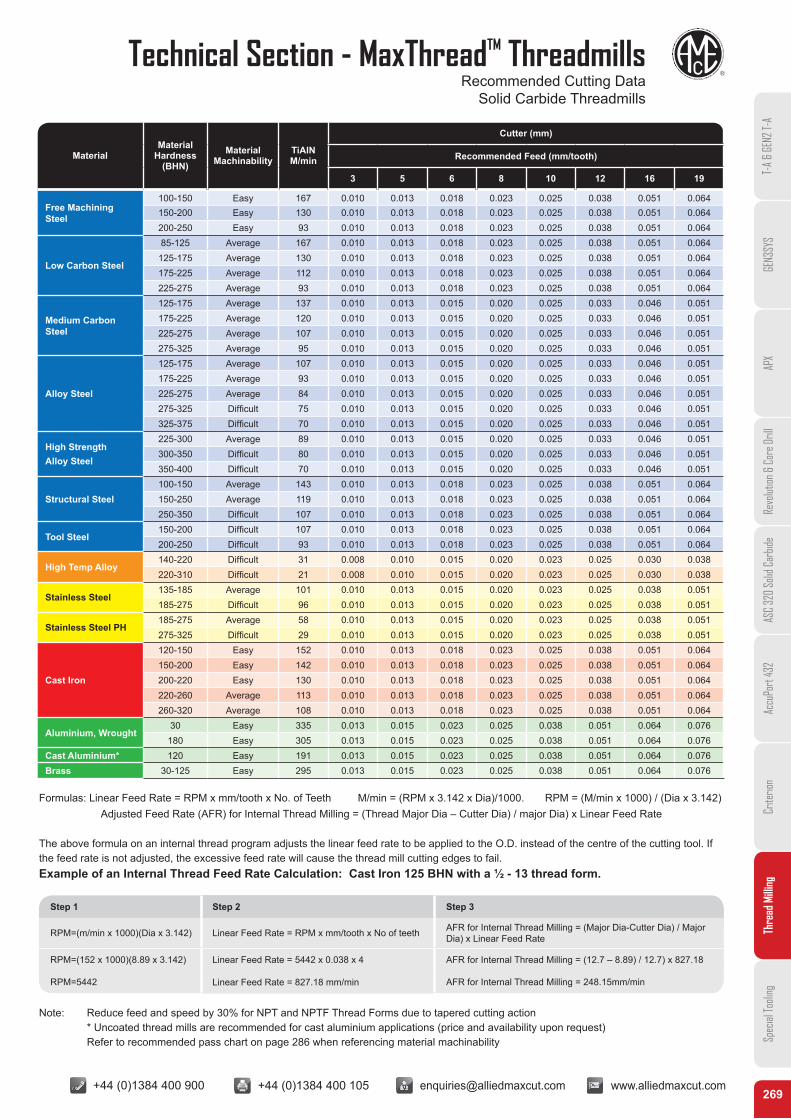
Technical Section - MaxThreadTM ThreadmillsRecommended Cutting Data
Solid Carbide Threadmills
T-A
& GE
N2 T-
AGE
N3SY
SAP
XRe
volut
ion &
Cor
e Dril
lAS
C 32
0 So
lid C
arbid
eAc
cuPo
rt 43
2Cr
iterio
nTh
read
Milli
ngSp
ecial
Tooli
ng
MaterialMaterial
Hardness(BHN)
MaterialMachinability
TiAlNM/min
Cutter (mm)
Recommended Feed (mm/tooth)
3 5 6 8 10 12 16 19
Free Machining Steel
100-150 Easy 167 0.010 0.013 0.018 0.023 0.025 0.038 0.051 0.064150-200 Easy 130 0.010 0.013 0.018 0.023 0.025 0.038 0.051 0.064200-250 Easy 93 0.010 0.013 0.018 0.023 0.025 0.038 0.051 0.064
Low Carbon Steel
85-125 Average 167 0.010 0.013 0.018 0.023 0.025 0.038 0.051 0.064125-175 Average 130 0.010 0.013 0.018 0.023 0.025 0.038 0.051 0.064175-225 Average 112 0.010 0.013 0.018 0.023 0.025 0.038 0.051 0.064225-275 Average 93 0.010 0.013 0.018 0.023 0.025 0.038 0.051 0.064
Medium Carbon Steel
125-175 Average 137 0.010 0.013 0.015 0.020 0.025 0.033 0.046 0.051175-225 Average 120 0.010 0.013 0.015 0.020 0.025 0.033 0.046 0.051225-275 Average 107 0.010 0.013 0.015 0.020 0.025 0.033 0.046 0.051275-325 Average 95 0.010 0.013 0.015 0.020 0.025 0.033 0.046 0.051
Alloy Steel
125-175 Average 107 0.010 0.013 0.015 0.020 0.025 0.033 0.046 0.051175-225 Average 93 0.010 0.013 0.015 0.020 0.025 0.033 0.046 0.051225-275 Average 84 0.010 0.013 0.015 0.020 0.025 0.033 0.046 0.051275-325 Difficult 75 0.010 0.013 0.015 0.020 0.025 0.033 0.046 0.051325-375 Difficult 70 0.010 0.013 0.015 0.020 0.025 0.033 0.046 0.051
High StrengthAlloy Steel
225-300 Average 89 0.010 0.013 0.015 0.020 0.025 0.033 0.046 0.051300-350 Difficult 80 0.010 0.013 0.015 0.020 0.025 0.033 0.046 0.051350-400 Difficult 70 0.010 0.013 0.015 0.020 0.025 0.033 0.046 0.051
Structural Steel100-150 Average 143 0.010 0.013 0.018 0.023 0.025 0.038 0.051 0.064150-250 Average 119 0.010 0.013 0.018 0.023 0.025 0.038 0.051 0.064250-350 Difficult 107 0.010 0.013 0.018 0.023 0.025 0.038 0.051 0.064
Tool Steel150-200 Difficult 107 0.010 0.013 0.018 0.023 0.025 0.038 0.051 0.064200-250 Difficult 93 0.010 0.013 0.018 0.023 0.025 0.038 0.051 0.064
High Temp Alloy140-220 Difficult 31 0.008 0.010 0.015 0.020 0.023 0.025 0.030 0.038220-310 Difficult 21 0.008 0.010 0.015 0.020 0.023 0.025 0.030 0.038
Stainless Steel135-185 Average 101 0.010 0.013 0.015 0.020 0.023 0.025 0.038 0.051185-275 Difficult 96 0.010 0.013 0.015 0.020 0.023 0.025 0.038 0.051
Stainless Steel PH185-275 Average 58 0.010 0.013 0.015 0.020 0.023 0.025 0.038 0.051275-325 Difficult 29 0.010 0.013 0.015 0.020 0.023 0.025 0.038 0.051
Cast Iron
120-150 Easy 152 0.010 0.013 0.018 0.023 0.025 0.038 0.051 0.064150-200 Easy 142 0.010 0.013 0.018 0.023 0.025 0.038 0.051 0.064200-220 Easy 130 0.010 0.013 0.018 0.023 0.025 0.038 0.051 0.064220-260 Average 113 0.010 0.013 0.018 0.023 0.025 0.038 0.051 0.064260-320 Average 108 0.010 0.013 0.018 0.023 0.025 0.038 0.051 0.064
Aluminium, Wrought30 Easy 335 0.013 0.015 0.023 0.025 0.038 0.051 0.064 0.076
180 Easy 305 0.013 0.015 0.023 0.025 0.038 0.051 0.064 0.076Cast Aluminium* 120 Easy 191 0.013 0.015 0.023 0.025 0.038 0.051 0.064 0.076Brass 30-125 Easy 295 0.013 0.015 0.023 0.025 0.038 0.051 0.064 0.076
Formulas: Linear Feed Rate = RPM x mm/tooth x No. of Teeth M/min = (RPM x 3.142 x Dia)/1000. RPM = (M/min x 1000) / (Dia x 3.142)Adjusted Feed Rate (AFR) for Internal Thread Milling = (Thread Major Dia – Cutter Dia) / major Dia) x Linear Feed Rate
The above formula on an internal thread program adjusts the linear feed rate to be applied to the O.D. instead of the centre of the cutting tool. If the feed rate is not adjusted, the excessive feed rate will cause the thread mill cutting edges to fail.Example of an Internal Thread Feed Rate Calculation: Cast Iron 125 BHN with a ½ - 13 thread form.
Note: Reduce feed and speed by 30% for NPT and NPTF Thread Forms due to tapered cutting action * Uncoated thread mills are recommended for cast aluminium applications (price and availability upon request) Refer to recommended pass chart on page 286 when referencing material machinability
Step 1 Step 2 Step 3
RPM=(m/min x 1000)(Dia x 3.142) Linear Feed Rate = RPM x mm/tooth x No of teeth AFR for Internal Thread Milling = (Major Dia-Cutter Dia) / Major Dia) x Linear Feed Rate
RPM=(152 x 1000)(8.89 x 3.142) Linear Feed Rate = 5442 x 0.038 x 4 AFR for Internal Thread Milling = (12.7 – 8.89) / 12.7) x 827.18
RPM=5442 Linear Feed Rate = 827.18 mm/min AFR for Internal Thread Milling = 248.15mm/min
+44 (0)1384 400 900 +44 (0)1384 400 105 [email protected] www.alliedmaxcut.com +44 (0)1384 400 900 +44 (0)1384 400 105 [email protected] www.alliedmaxcut.com270
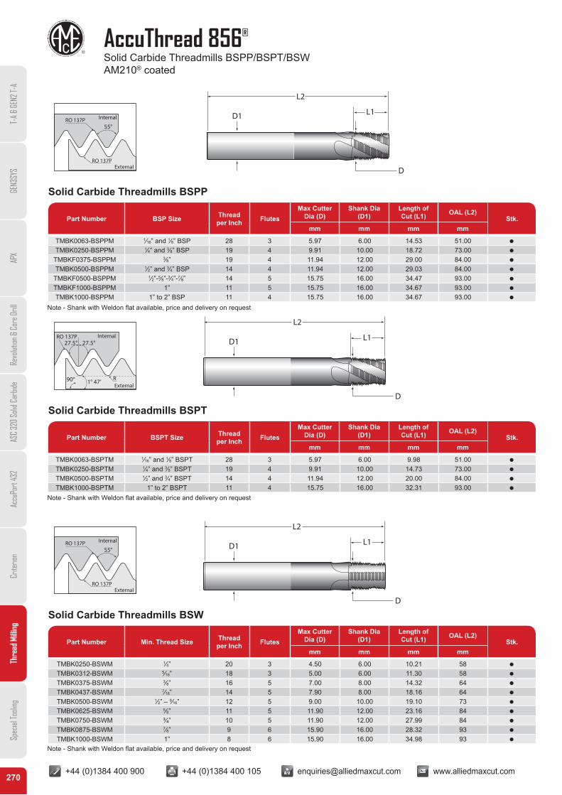
AccuThread 856®
Solid Carbide Threadmills BSPP/BSPT/BSWAM210® coated
T-A
& GE
N2 T-
AGE
N3SY
SAP
XRe
volut
ion &
Cor
e Dril
lAS
C 32
0 So
lid C
arbid
eAc
cuPo
rt 43
2Cr
iterio
nTh
read
Milli
ngSp
ecial
Tooli
ng
55°
External
InternalRO 137P
RO 137P
Solid Carbide Threadmills BSPP
Part Number BSP Size Thread per Inch Flutes
Max Cutter Dia (D)
Shank Dia (D1)
Length of Cut (L1) OAL (L2)
Stk.mm mm mm mm
TMBK0063-BSPPM 1⁄16” and 1⁄8” BSP 28 3 5.97 6.00 14.53 51.00 Q
TMBK0250-BSPPM 1⁄4” and 3⁄8” BSP 19 4 9.91 10.00 18.72 73.00 Q
TMBKF0375-BSPPM 3⁄8” 19 4 11.94 12.00 29.00 84.00 Q
TMBK0500-BSPPM 1⁄2” and 3⁄4” BSP 14 4 11.94 12.00 29.03 84.00 Q
TMBKF0500-BSPPM 1⁄2”-5⁄8”-3⁄4”-7⁄8” 14 5 15.75 16.00 34.47 93.00 Q
TMBKF1000-BSPPM 1” 11 5 15.75 16.00 34.67 93.00 Q
TMBK1000-BSPPM 1” to 2” BSP 11 4 15.75 16.00 34.67 93.00 Q
D1
L2
L1
D
90°
27.5°27.5°RO 137P
R1° 47’
Internal
External
D1
L2
L1
D
Solid Carbide Threadmills BSPT
Part Number BSPT Size Thread per Inch Flutes
Max Cutter Dia (D)
Shank Dia (D1)
Length of Cut (L1) OAL (L2)
Stk.mm mm mm mm
TMBK0063-BSPTM 1⁄16” and 1⁄8” BSPT 28 3 5.97 6.00 9.98 51.00 Q
TMBK0250-BSPTM 1⁄4” and 3⁄8” BSPT 19 4 9.91 10.00 14.73 73.00 Q
TMBK0500-BSPTM 1⁄2” and 3⁄4” BSPT 14 4 11.94 12.00 20.00 84.00 Q
TMBK1000-BSPTM 1” to 2” BSPT 11 4 15.75 16.00 32.31 93.00 Q
55°
External
InternalRO 137P
RO 137P
D1
L2
L1
D
Solid Carbide Threadmills BSW
Part Number Min. Thread Size Thread per Inch Flutes
Max Cutter Dia (D)
Shank Dia (D1)
Length of Cut (L1) OAL (L2)
Stk.mm mm mm mm
TMBK0250-BSWM 1⁄4” 20 3 4.50 6.00 10.21 58 Q
TMBK0312-BSWM 5⁄16” 18 3 5.00 6.00 11.30 58 Q
TMBK0375-BSWM 3⁄8” 16 5 7.00 8.00 14.32 64 Q
TMBK0437-BSWM 7⁄16” 14 5 7.90 8.00 18.16 64 Q
TMBK0500-BSWM 1⁄2” – 9⁄16” 12 5 9.00 10.00 19.10 73 Q
TMBK0625-BSWM 5⁄8” 11 5 11.90 12.00 23.16 84 Q
TMBK0750-BSWM ¾” 10 5 11.90 12.00 27.99 84 Q
TMBK0875-BSWM 7⁄8” 9 6 15.90 16.00 28.32 93 Q
TMBK1000-BSWM 1” 8 6 15.90 16.00 34.98 93 Q
Note - Shank with Weldon flat available, price and delivery on request
Note - Shank with Weldon flat available, price and delivery on request
Note - Shank with Weldon flat available, price and delivery on request
+44 (0)1384 400 900 +44 (0)1384 400 105 [email protected] www.alliedmaxcut.com +44 (0)1384 400 900 +44 (0)1384 400 105 [email protected] www.alliedmaxcut.com271
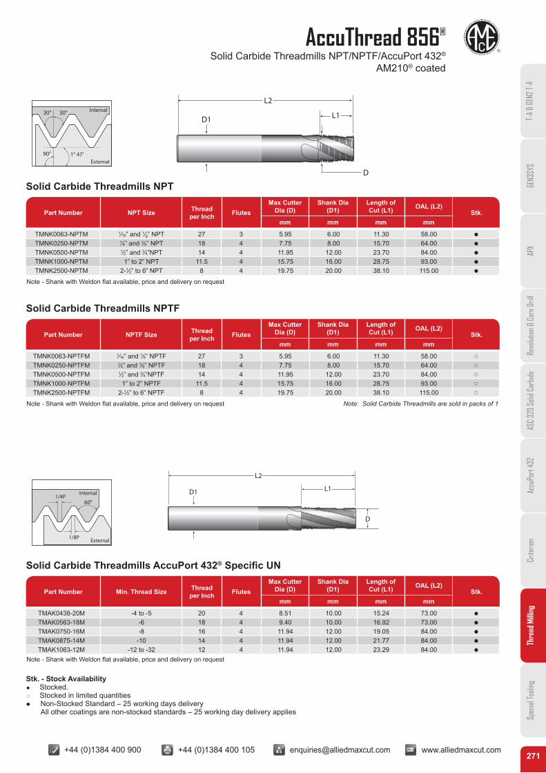
AccuThread 856®
Solid Carbide Threadmills NPT/NPTF/AccuPort 432®
AM210® coated
T-A
& GE
N2 T-
AGE
N3SY
SAP
XRe
volut
ion &
Cor
e Dril
lAS
C 32
0 So
lid C
arbid
eAc
cuPo
rt 43
2Cr
iterio
nTh
read
Milli
ngSp
ecial
Tooli
ng
90° 1° 47’
30° 30°
External
Internal
D1
L2
L1
D
Solid Carbide Threadmills NPT
Part Number NPT Size Thread per Inch Flutes
Max Cutter Dia (D)
Shank Dia (D1)
Length of Cut (L1) OAL (L2)
Stk.mm mm mm mm
TMNK0063-NPTM 1⁄16” and 1⁄8” NPT 27 3 5.95 6.00 11.30 58.00 Q
TMNK0250-NPTM 1⁄4” and 3⁄8” NPT 18 4 7.75 8.00 15.70 64.00 Q
TMNK0500-NPTM 1⁄2” and 3⁄4”NPT 14 4 11.95 12.00 23.70 84.00 Q
TMNK1000-NPTM 1” to 2” NPT 11.5 4 15.75 16.00 28.75 93.00 Q
TMNK2500-NPTM 2-1⁄2” to 6” NPT 8 4 19.75 20.00 38.10 115.00 Q
Solid Carbide Threadmills NPTF
Part Number NPTF Size Thread per Inch Flutes
Max Cutter Dia (D)
Shank Dia (D1)
Length of Cut (L1) OAL (L2)
Stk.mm mm mm mm
TMNK0063-NPTFM 1⁄16” and 1⁄8” NPTF 27 3 5.95 6.00 11.30 58.00 p
TMNK0250-NPTFM 1⁄4” and 3⁄8” NPTF 18 4 7.75 8.00 15.70 64.00 p
TMNK0500-NPTFM 1⁄2” and 3⁄4”NPTF 14 4 11.95 12.00 23.70 84.00 p
TMNK1000-NPTFM 1” to 2” NPTF 11.5 4 15.75 16.00 28.75 93.00 p
TMNK2500-NPTFM 2-1⁄2” to 6” NPTF 8 4 19.75 20.00 38.10 115.00 p
Note: Solid Carbide Threadmills are sold in packs of 1
60°1/4P
1/8P
Internal
External
D1
L2
L1
D
Solid Carbide Threadmills AccuPort 432® Specific UN
Part Number Min. Thread Size Thread per Inch Flutes
Max Cutter Dia (D)
Shank Dia (D1)
Length of Cut (L1) OAL (L2)
Stk.mm mm mm mm
TMAK0438-20M -4 to -5 20 4 8.51 10.00 15.24 73.00 Q
TMAK0563-18M -6 18 4 9.40 10.00 16.92 73.00 Q
TMAK0750-16M -8 16 4 11.94 12.00 19.05 84.00 Q
TMAK0875-14M -10 14 4 11.94 12.00 21.77 84.00 Q
TMAK1063-12M -12 to -32 12 4 11.94 12.00 23.29 84.00 Q
Stk. - Stock Availability Q Stocked. q Stocked in limited quantitiesu Non-Stocked Standard – 25 working days delivery
All other coatings are non-stocked standards – 25 working day delivery applies
Note - Shank with Weldon flat available, price and delivery on request
Note - Shank with Weldon flat available, price and delivery on request
Note - Shank with Weldon flat available, price and delivery on request
+44 (0)1384 400 900 +44 (0)1384 400 105 [email protected] www.alliedmaxcut.com +44 (0)1384 400 900 +44 (0)1384 400 105 [email protected] www.alliedmaxcut.com272
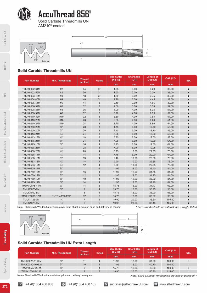
AccuThread 856®
Solid Carbide Threadmills UN AM210® coated
T-A
& GE
N2 T-
AGE
N3SY
SAP
XRe
volut
ion &
Cor
e Dril
lAS
C 32
0 So
lid C
arbid
eAc
cuPo
rt 43
2Cr
iterio
nTh
read
Milli
ngSp
ecial
Tooli
ng
60°1/4P
1/8P
Internal
External
D1
L2
L1
D
Solid Carbide Threadmills UN
Part Number Min. Thread Size Thread per Inch Flutes
Max Cutter Dia (D)
Shank Dia (D1)
Length of Cut (L1) OAL (L2)
Stk.mm mm mm mm
TMUK0002-64M #2 64 3* 1.65 3.00 3.20 39.00 Q
TMUK0002-56M #2 56 3* 1.65 3.00 3.20 39.00 Q
TMUK0003-48M #3 48 3* 1.80 3.00 3.75 39.00 Q
TMUK0004-40M #4 40 3* 2.20 3.00 4.45 39.00 Q
TMUK0005-44M #5 44 3 2.40 3.00 4.65 39.00 Q
TMUK0006-32M #6 32 3 2.50 3.00 5.55 39.00 Q
TMUK0008-36M #8 36 3 3.00 4.00 6.35 51.00 Q
TMUK0008-32M #8 32 3 3.20 4.00 6.35 51.00 Q
TMUK0010-32M #10 32 3 3.80 4.00 7.95 51.00 Q
TMUK0010-28M #10 28 3 3.80 4.00 8.20 51.00 Q
TMUK0010-24M #10 24 3 3.70 4.00 8.50 51.00 Q
TMUK0250-28M 1⁄4” 28 3 4.75 6.00 12.70 58.00 Q
TMUK0250-20M 1⁄4” 20 3 4.75 6.00 12.70 58.00 Q
TMUK0313-24M 5⁄16” 24 3 5.95 6.00 16.00 58.00 Q
TMUK0313-18M 5⁄16” 18 3 5.95 6.00 17.00 58.00 Q
TMUK0375-24M 3⁄8” 24 4 7.25 8.00 19.00 64.00 Q
TMUK0375-16M 3⁄8” 16 4 7.25 8.00 19.00 64.00 Q
TMUK0438-28M 7⁄16” 28 4 7.90 8.00 19.95 64.00 Q
TMUK0438-20M 7⁄16” 20 4 8.75 10.00 22.85 73.00 Q
TMUK0438-14M 7⁄16” 14 4 7.75 8.00 20.00 64.00 Q
TMUK0500-13M 1⁄2” 13 4 9.40 10.00 23.50 73.00 Q
TMUK0563-18M 9⁄16” 18 4 9.90 10.00 22.65 73.00 Q
TMUK0563-12M 9⁄16” 12 4 9.90 10.00 22.65 73.00 Q
TMUK0625-11M 5⁄8” 11 4 11.95 12.00 32.40 84.00 Q
TMUK0750-16M 3⁄4” 16 4 11.95 12.00 31.75 84.00 Q
TMUK0750-12M 3⁄4” 12 4 11.95 12.00 31.75 84.00 Q
TMUK0750-10M 3⁄4” 10 4 11.95 12.00 33.00 84.00 Q
TMUK0875-14M 7⁄8” 14 4 11.95 12.00 32.70 84.00 Q
TMUKF0875-14M 7⁄8” 14 5 15.75 16.00 34.47 93.00 Q
TMUK0875-9M 7⁄8” 9 4 15.75 16.00 36.75 93.00 Q
TMUK1000-8M 1” 8 4 15.75 16.00 35.00 93.00 Q
TMUKF1000-12M 1”-1”1⁄16-1”1⁄8-1”1⁄4” 12 5 15.75 16.00 33.87 93.00 Q
TMUK1125-7M 11⁄8” 7 5 19.90 20.00 36.30 105.00 Q
TMUK1375-6M 13⁄8” 6 5 19.90 20.00 38.10 105.00 Q
* Items marked with an asterisk are straight fluted
Note: Solid Carbide Threadmills are sold in packs of 1
60°1/4P
1/8P
Internal
External
D1
L2
L1
D
Solid Carbide Threadmills UN Extra Length
Part Number Min. Thread Size Thread per Inch Flutes
Max Cutter Dia (D)
Shank Dia (D1)
Length of Cut (L1) OAL (L2)
Stk.mm mm mm mm
TMUK0625-11XLM 5⁄8” 11 4 11.95 12.00 37.00 100.00 p
TMUK0750-10XLM 3⁄4” 10 4 11.95 12.00 40.70 100.00 p
TMUK0875-9XLM 7⁄8” 9 4 15.75 16.00 45.20 100.00 p
TMUK1000-8XLM 1” 8 6 19.90 20.00 50.80 115.00 p
Note - Shank with Weldon flat available over 6mm shank diameter, price and delivery on request
Note - Shank with Weldon flat available, price and delivery on request
+44 (0)1384 400 900 +44 (0)1384 400 105 [email protected] www.alliedmaxcut.com +44 (0)1384 400 900 +44 (0)1384 400 105 [email protected] www.alliedmaxcut.com273
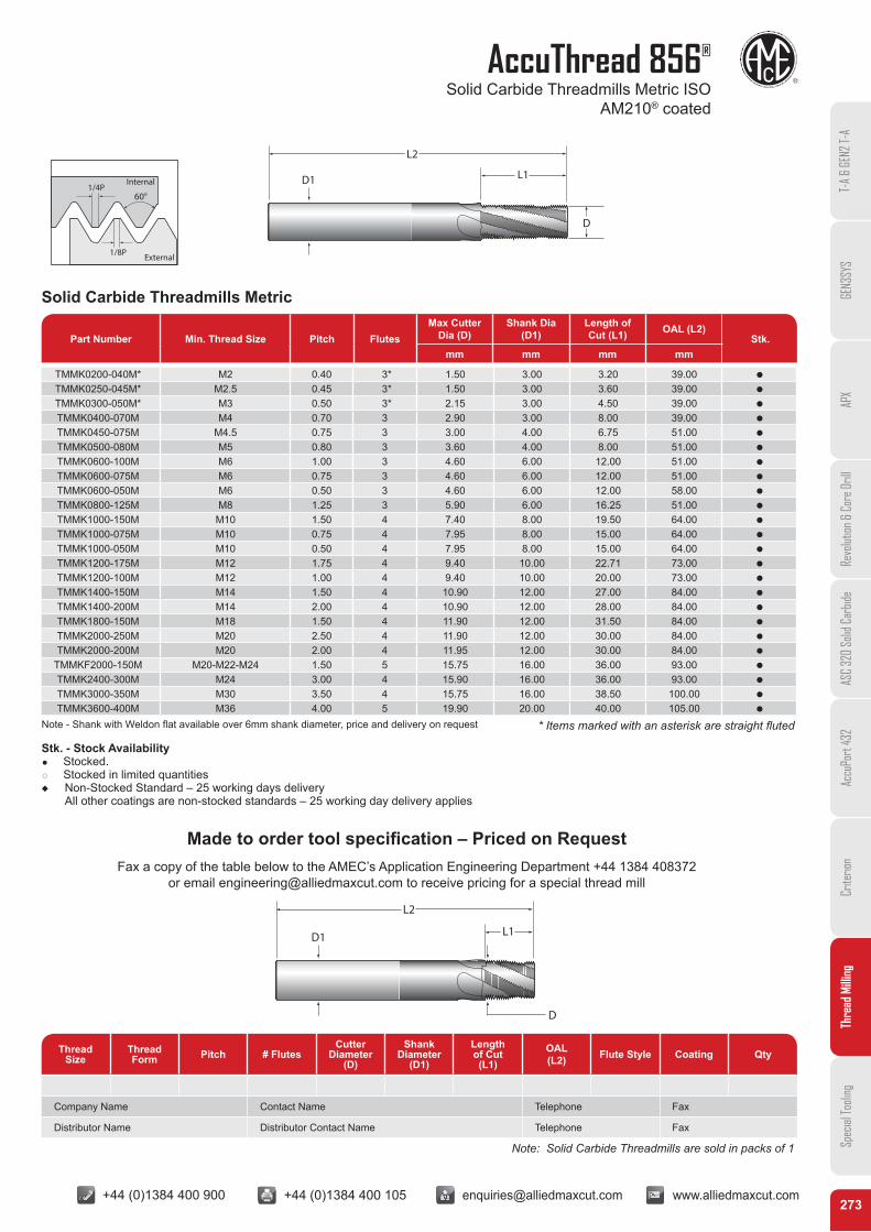
AccuThread 856®
Solid Carbide Threadmills Metric ISO AM210® coated
T-A
& GE
N2 T-
AGE
N3SY
SAP
XRe
volut
ion &
Cor
e Dril
lAS
C 32
0 So
lid C
arbid
eAc
cuPo
rt 43
2Cr
iterio
nTh
read
Milli
ngSp
ecial
Tooli
ng
60°1/4P
1/8P
Internal
External
D1
L2
L1
D
Solid Carbide Threadmills Metric
Part Number Min. Thread Size Pitch FlutesMax Cutter
Dia (D)Shank Dia
(D1)Length of Cut (L1) OAL (L2)
Stk.mm mm mm mm
TMMK0200-040M* M2 0.40 3* 1.50 3.00 3.20 39.00 Q
TMMK0250-045M* M2.5 0.45 3* 1.50 3.00 3.60 39.00 Q
TMMK0300-050M* M3 0.50 3* 2.15 3.00 4.50 39.00 Q
TMMK0400-070M M4 0.70 3 2.90 3.00 8.00 39.00 Q
TMMK0450-075M M4.5 0.75 3 3.00 4.00 6.75 51.00 Q
TMMK0500-080M M5 0.80 3 3.60 4.00 8.00 51.00 Q
TMMK0600-100M M6 1.00 3 4.60 6.00 12.00 51.00 Q
TMMK0600-075M M6 0.75 3 4.60 6.00 12.00 51.00 Q
TMMK0600-050M M6 0.50 3 4.60 6.00 12.00 58.00 Q
TMMK0800-125M M8 1.25 3 5.90 6.00 16.25 51.00 Q
TMMK1000-150M M10 1.50 4 7.40 8.00 19.50 64.00 Q
TMMK1000-075M M10 0.75 4 7.95 8.00 15.00 64.00 Q
TMMK1000-050M M10 0.50 4 7.95 8.00 15.00 64.00 Q
TMMK1200-175M M12 1.75 4 9.40 10.00 22.71 73.00 Q
TMMK1200-100M M12 1.00 4 9.40 10.00 20.00 73.00 Q
TMMK1400-150M M14 1.50 4 10.90 12.00 27.00 84.00 Q
TMMK1400-200M M14 2.00 4 10.90 12.00 28.00 84.00 Q
TMMK1800-150M M18 1.50 4 11.90 12.00 31.50 84.00 Q
TMMK2000-250M M20 2.50 4 11.90 12.00 30.00 84.00 Q
TMMK2000-200M M20 2.00 4 11.95 12.00 30.00 84.00 Q
TMMKF2000-150M M20-M22-M24 1.50 5 15.75 16.00 36.00 93.00 Q
TMMK2400-300M M24 3.00 4 15.90 16.00 36.00 93.00 Q
TMMK3000-350M M30 3.50 4 15.75 16.00 38.50 100.00 Q
TMMK3600-400M M36 4.00 5 19.90 20.00 40.00 105.00 Q
* Items marked with an asterisk are straight fluted
Note: Solid Carbide Threadmills are sold in packs of 1
Stk. - Stock Availability Q Stocked. q Stocked in limited quantitiesu Non-Stocked Standard – 25 working days delivery
All other coatings are non-stocked standards – 25 working day delivery applies
Made to order tool specification – Priced on RequestFax a copy of the table below to the AMEC’s Application Engineering Department +44 1384 408372
or email [email protected] to receive pricing for a special thread mill
D1
L2
L1
D
Thread Size
Thread Form Pitch # Flutes
Cutter Diameter
(D)
Shank Diameter
(D1)
Length of Cut(L1)
OAL (L2) Flute Style Coating Qty
Company Name Contact Name Telephone Fax
Distributor Name Distributor Contact Name Telephone Fax
Note - Shank with Weldon flat available over 6mm shank diameter, price and delivery on request
+44 (0)1384 400 900 +44 (0)1384 400 105 [email protected] www.alliedmaxcut.com +44 (0)1384 400 900 +44 (0)1384 400 105 [email protected] www.alliedmaxcut.com274
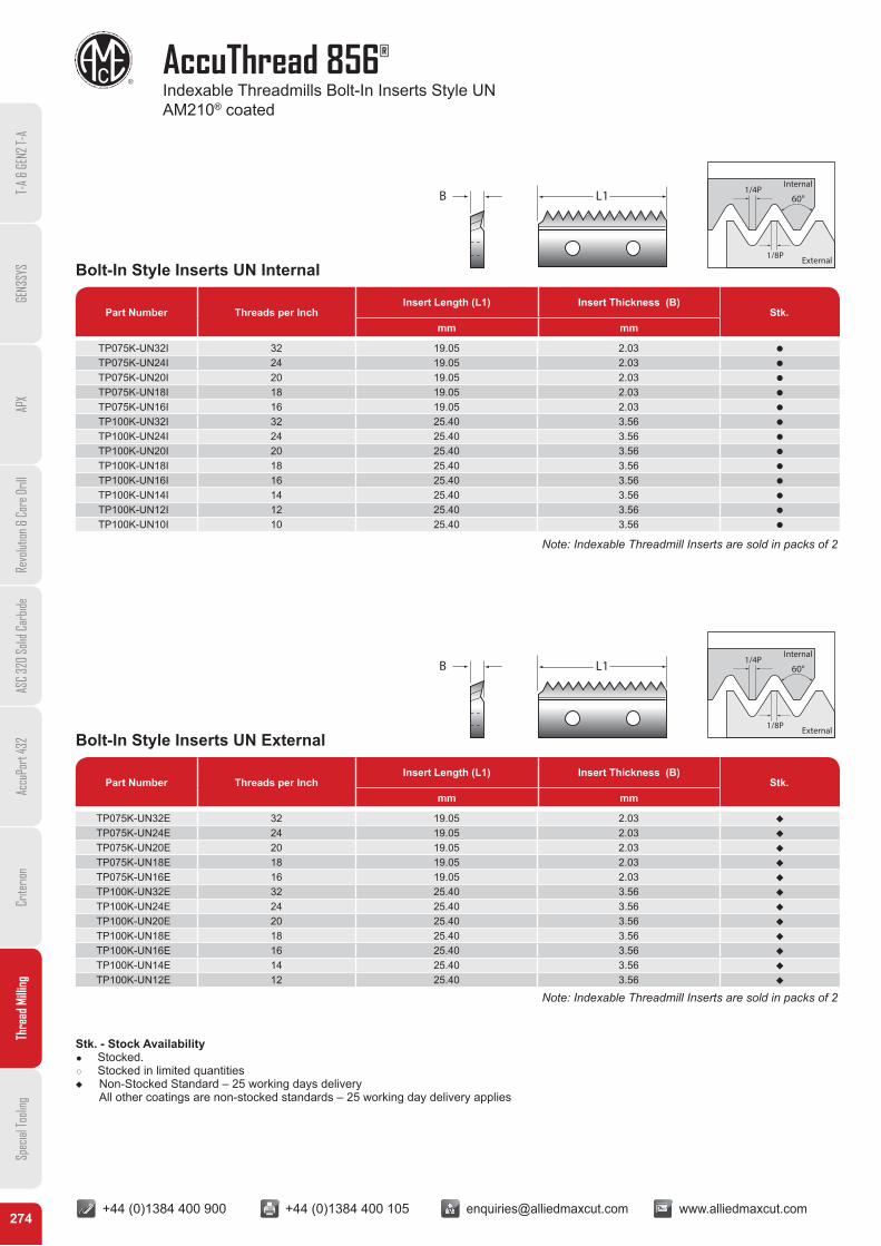
AccuThread 856®
Indexable Threadmills Bolt-In Inserts Style UN AM210® coated
T-A
& GE
N2 T-
AGE
N3SY
SAP
XRe
volut
ion &
Cor
e Dril
lAS
C 32
0 So
lid C
arbid
eAc
cuPo
rt 43
2Cr
iterio
nTh
read
Milli
ngSp
ecial
Tooli
ng
Bolt-In Style Inserts UN Internal
Bolt-In Style Inserts UN External
Part Number Threads per InchInsert Length (L1) Insert Thickness (B)
Stk.mm mm
Part Number Threads per InchInsert Length (L1) Insert Thickness (B)
Stk.mm mm
TP075K-UN32I 32 19.05 2.03 Q
TP075K-UN24I 24 19.05 2.03 Q
TP075K-UN20I 20 19.05 2.03 Q
TP075K-UN18I 18 19.05 2.03 Q
TP075K-UN16I 16 19.05 2.03 Q
TP100K-UN32I 32 25.40 3.56 Q
TP100K-UN24I 24 25.40 3.56 Q
TP100K-UN20I 20 25.40 3.56 Q
TP100K-UN18I 18 25.40 3.56 Q
TP100K-UN16I 16 25.40 3.56 Q
TP100K-UN14I 14 25.40 3.56 Q
TP100K-UN12I 12 25.40 3.56 Q
TP100K-UN10I 10 25.40 3.56 Q
TP075K-UN32E 32 19.05 2.03 R
TP075K-UN24E 24 19.05 2.03 R
TP075K-UN20E 20 19.05 2.03 R
TP075K-UN18E 18 19.05 2.03 R
TP075K-UN16E 16 19.05 2.03 R
TP100K-UN32E 32 25.40 3.56 R
TP100K-UN24E 24 25.40 3.56 R
TP100K-UN20E 20 25.40 3.56 R
TP100K-UN18E 18 25.40 3.56 R
TP100K-UN16E 16 25.40 3.56 R
TP100K-UN14E 14 25.40 3.56 R
TP100K-UN12E 12 25.40 3.56 R
60°1/4P
1/8P
Internal
External
60°1/4P
1/8P
Internal
External
L1B
L1B
Note: Indexable Threadmill Inserts are sold in packs of 2
Note: Indexable Threadmill Inserts are sold in packs of 2
Stk. - Stock Availability Q Stocked. q Stocked in limited quantitiesu Non-Stocked Standard – 25 working days delivery
All other coatings are non-stocked standards – 25 working day delivery applies
+44 (0)1384 400 900 +44 (0)1384 400 105 [email protected] www.alliedmaxcut.com +44 (0)1384 400 900 +44 (0)1384 400 105 [email protected] www.alliedmaxcut.com275
AccuThread 856®
Indexable Threadmills Bolt-In Inserts Style UNJ AM210® coated
T-A
& GE
N2 T-
AGE
N3SY
SAP
XRe
volut
ion &
Cor
e Dril
lAS
C 32
0 So
lid C
arbid
eAc
cuPo
rt 43
2Cr
iterio
nTh
read
Milli
ngSp
ecial
Tooli
ng
Part Number Threads per InchInsert Length (L1) Insert Thickness (B)
Stk.mm mm
Part Number Threads per InchInsert Length (L1) Insert Thickness (B)
Stk.mm mm
Bolt-In Style Inserts UNJ Internal
Bolt-In Style Inserts UNJ External
Part Number Threads per InchInsert Length (L1) Insert Thickness (B)
Stk.mm mm
Part Number Threads per InchInsert Length (L1) Insert Thickness (B)
Stk.mm mm
TP075K-UNJ32I 32 19.05 2.03 R
TP075K-UNJ24I 24 19.05 2.03 R
TP075K-UNJ20I 20 19.05 2.03 R
TP075K-UNJ18I 18 19.05 2.03 R
TP075K-UNJ16I 16 19.05 2.03 R
TP100K-UNJ32I 32 25.40 3.56 R
TP100K-UNJ24I 24 25.40 3.56 R
TP100K-UNJ20I 20 25.40 3.56 R
TP100K-UNJ18I 18 25.40 3.56 R
TP100K-UNJ16I 16 25.40 3.56 R
TP100K-UNJ14I 14 25.40 3.56 R
TP100K-UNJ12I 12 19.05 2.03 R
TP075K-UNJ32E 32 19.05 2.03 R
TP075K-UNJ24E 24 19.05 2.03 R
TP075K-UNJ20E 20 19.05 2.03 R
TP075K-UNJ18E 18 19.05 2.03 R
TP075K-UNJ16E 16 19.05 2.03 R
TP100K-UNJ32E 32 25.40 3.56 R
TP100K-UNJ24E 24 25.40 3.56 R
TP100K-UNJ20E 20 25.40 3.56 R
TP100K-UNJ18E 18 25.40 3.56 R
TP100K-UNJ16E 16 25.40 3.56 R
TP100K-UNJ12E 12 25.40 3.56 R
60°5/16P
R max 0.18042PR min 0.15011P External
Internal
60°5/16P
R max 0.18042PR min 0.15011P External
Internal
L1B
L1B
Note: Indexable Threadmill Inserts are sold in packs of 2
Note: Indexable Threadmill Inserts are sold in packs of 2
Stk. - Stock Availability Q Stocked. q Stocked in limited quantitiesu Non-Stocked Standard – 25 working days delivery
All other coatings are non-stocked standards – 25 working day delivery applies
+44 (0)1384 400 900 +44 (0)1384 400 105 [email protected] www.alliedmaxcut.com +44 (0)1384 400 900 +44 (0)1384 400 105 [email protected] www.alliedmaxcut.com276
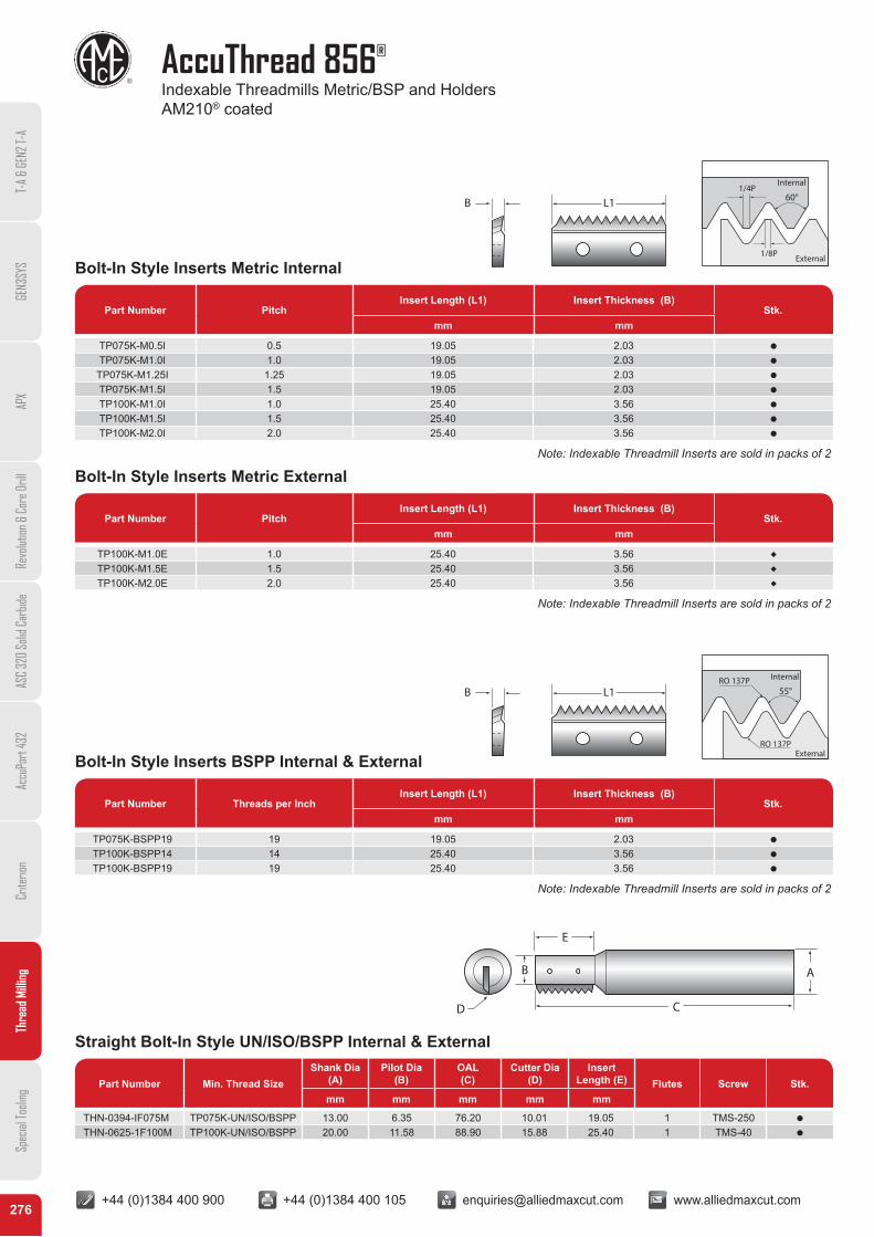
AccuThread 856®
Indexable Threadmills Metric/BSP and Holders AM210® coated
T-A
& GE
N2 T-
AGE
N3SY
SAP
XRe
volut
ion &
Cor
e Dril
lAS
C 32
0 So
lid C
arbid
eAc
cuPo
rt 43
2Cr
iterio
nTh
read
Milli
ngSp
ecial
Tooli
ng
Bolt-In Style Inserts Metric Internal
Bolt-In Style Inserts Metric External
Bolt-In Style Inserts BSPP Internal & External
Part Number PitchInsert Length (L1) Insert Thickness (B)
Stk.mm mm
Part Number PitchInsert Length (L1) Insert Thickness (B)
Stk.mm mm
Part Number Threads per InchInsert Length (L1) Insert Thickness (B)
Stk.mm mm
TP075K-M0.5I 0.5 19.05 2.03 Q
TP075K-M1.0I 1.0 19.05 2.03 Q
TP075K-M1.25I 1.25 19.05 2.03 Q
TP075K-M1.5I 1.5 19.05 2.03 Q
TP100K-M1.0I 1.0 25.40 3.56 Q
TP100K-M1.5I 1.5 25.40 3.56 Q
TP100K-M2.0I 2.0 25.40 3.56 Q
TP100K-M1.0E 1.0 25.40 3.56 R
TP100K-M1.5E 1.5 25.40 3.56 R
TP100K-M2.0E 2.0 25.40 3.56 R
TP075K-BSPP19 19 19.05 2.03 Q
TP100K-BSPP14 14 25.40 3.56 Q
TP100K-BSPP19 19 25.40 3.56 Q
60°1/4P
1/8P
Internal
External
55°
External
InternalRO 137P
RO 137P
L1B
L1B
Note: Indexable Threadmill Inserts are sold in packs of 2
Note: Indexable Threadmill Inserts are sold in packs of 2
Note: Indexable Threadmill Inserts are sold in packs of 2
Straight Bolt-In Style UN/ISO/BSPP Internal & External
Part Number Min. Thread SizeShank Dia
(A)Pilot Dia
(B)OAL (C)
Cutter Dia (D)
Insert Length (E) Flutes Screw Stk.
mm mm mm mm mm
THN-0394-IF075M TP075K-UN/ISO/BSPP 13.00 6.35 76.20 10.01 19.05 1 TMS-250 Q
THN-0625-1F100M TP100K-UN/ISO/BSPP 20.00 11.58 88.90 15.88 25.40 1 TMS-40 Q
B
C
A
E
D
+44 (0)1384 400 900 +44 (0)1384 400 105 [email protected] www.alliedmaxcut.com +44 (0)1384 400 900 +44 (0)1384 400 105 [email protected] www.alliedmaxcut.com277
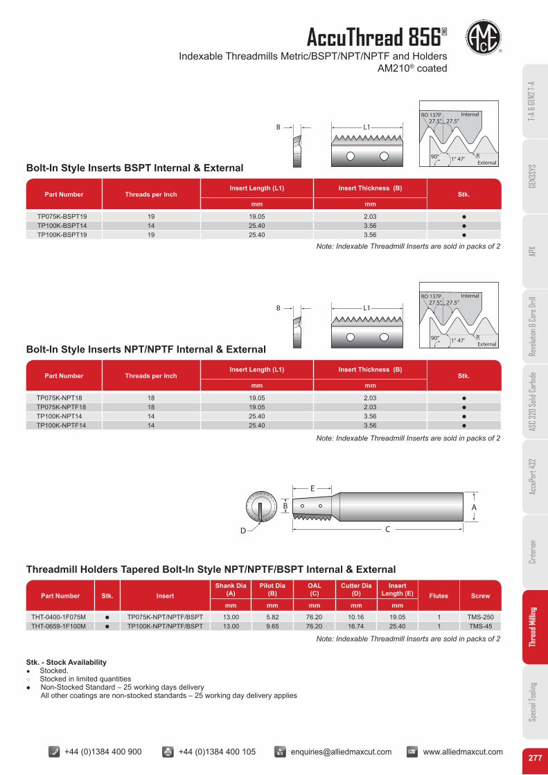
AccuThread 856®
Indexable Threadmills Metric/BSPT/NPT/NPTF and Holders AM210® coated
T-A
& GE
N2 T-
AGE
N3SY
SAP
XRe
volut
ion &
Cor
e Dril
lAS
C 32
0 So
lid C
arbid
eAc
cuPo
rt 43
2Cr
iterio
nTh
read
Milli
ngSp
ecial
Tooli
ng
Part Number PitchInsert Length (L1) Insert Thickness (B)
Stk.mm mm
Part Number PitchInsert Length (L1) Insert Thickness (B)
Stk.mm mm
Part Number Threads per InchInsert Length (L1) Insert Thickness (B)
Stk.mm mm
L1B
L1B
Bolt-In Style Inserts BSPT Internal & External
Bolt-In Style Inserts NPT/NPTF Internal & External
Part Number Threads per InchInsert Length (L1) Insert Thickness (B)
Stk.mm mm
Part Number Threads per InchInsert Length (L1) Insert Thickness (B)
Stk.mm mm
TP075K-BSPT19 19 19.05 2.03 Q
TP100K-BSPT14 14 25.40 3.56 Q
TP100K-BSPT19 19 25.40 3.56 Q
TP075K-NPT18 18 19.05 2.03 Q
TP075K-NPTF18 18 19.05 2.03 Q
TP100K-NPT14 14 25.40 3.56 Q
TP100K-NPTF14 14 25.40 3.56 Q
90°
27.5°27.5°RO 137P
R1° 47’
Internal
External
90°
27.5°27.5°RO 137P
R1° 47’
Internal
External
Note: Indexable Threadmill Inserts are sold in packs of 2
Note: Indexable Threadmill Inserts are sold in packs of 2
Threadmill Holders Tapered Bolt-In Style NPT/NPTF/BSPT Internal & External
Part Number Stk. InsertShank Dia
(A)Pilot Dia
(B)OAL (C)
Cutter Dia (D)
Insert Length (E) Flutes Screw
mm mm mm mm mm
THT-0400-1F075M Q TP075K-NPT/NPTF/BSPT 13.00 5.82 76.20 10.16 19.05 1 TMS-250THT-0659-1F100M Q TP100K-NPT/NPTF/BSPT 13.00 9.65 76.20 16.74 25.40 1 TMS-45
D
B
E
C
A
Stk. - Stock Availability Q Stocked. q Stocked in limited quantitiesu Non-Stocked Standard – 25 working days delivery
All other coatings are non-stocked standards – 25 working day delivery applies
Note: Indexable Threadmill Inserts are sold in packs of 2
+44 (0)1384 400 900 +44 (0)1384 400 105 [email protected] www.alliedmaxcut.com +44 (0)1384 400 900 +44 (0)1384 400 105 [email protected] www.alliedmaxcut.com278
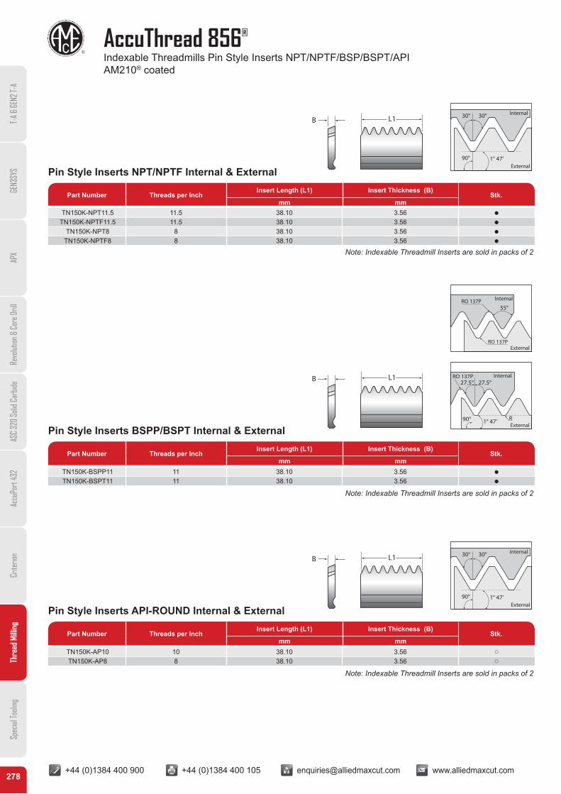
AccuThread 856®
Indexable Threadmills Pin Style Inserts NPT/NPTF/BSP/BSPT/API AM210® coated
T-A
& GE
N2 T-
AGE
N3SY
SAP
XRe
volut
ion &
Cor
e Dril
lAS
C 32
0 So
lid C
arbid
eAc
cuPo
rt 43
2Cr
iterio
nTh
read
Milli
ngSp
ecial
Tooli
ng
Pin Style Inserts NPT/NPTF Internal & External
Pin Style Inserts BSPP/BSPT Internal & External
Pin Style Inserts API-ROUND Internal & External
Part Number Threads per InchInsert Length (L1) Insert Thickness (B)
Stk.mm mm
Part Number Threads per InchInsert Length (L1) Insert Thickness (B)
Stk.mm mm
Part Number Threads per InchInsert Length (L1) Insert Thickness (B)
Stk.mm mm
TN150K-NPT11.5 11.5 38.10 3.56 Q
TN150K-NPTF11.5 11.5 38.10 3.56 Q
TN150K-NPT8 8 38.10 3.56 Q
TN150K-NPTF8 8 38.10 3.56 Q
TN150K-BSPP11 11 38.10 3.56 Q
TN150K-BSPT11 11 38.10 3.56 Q
TN150K-AP10 10 38.10 3.56 p
TN150K-AP8 8 38.10 3.56 p
L1B
L1B
L1B
90° 1° 47’
30° 30°
External
Internal
90°
27.5°27.5°RO 137P
R1° 47’
Internal
External
90° 1° 47’
30° 30°
External
Internal
55°
External
InternalRO 137P
RO 137P
Note: Indexable Threadmill Inserts are sold in packs of 2
Note: Indexable Threadmill Inserts are sold in packs of 2
Note: Indexable Threadmill Inserts are sold in packs of 2
+44 (0)1384 400 900 +44 (0)1384 400 105 [email protected] www.alliedmaxcut.com +44 (0)1384 400 900 +44 (0)1384 400 105 [email protected] www.alliedmaxcut.com279
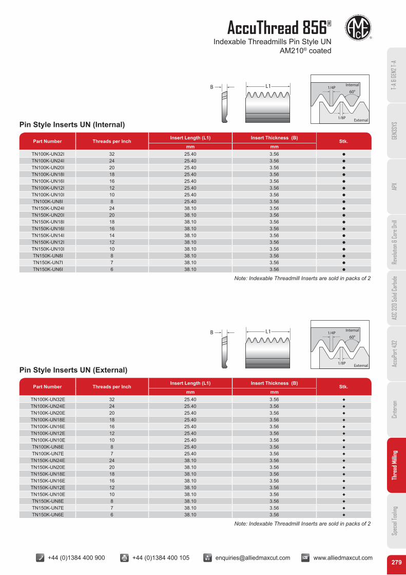
AccuThread 856®
Indexable Threadmills Pin Style UN AM210® coated
T-A
& GE
N2 T-
AGE
N3SY
SAP
XRe
volut
ion &
Cor
e Dril
lAS
C 32
0 So
lid C
arbid
eAc
cuPo
rt 43
2Cr
iterio
nTh
read
Milli
ngSp
ecial
Tooli
ng
Part Number Threads per InchInsert Length (L1) Insert Thickness (B)
Stk.mm mm
Part Number Threads per InchInsert Length (L1) Insert Thickness (B)
Stk.mm mm
Part Number Threads per InchInsert Length (L1) Insert Thickness (B)
Stk.mm mm
Pin Style Inserts UN (Internal)
Pin Style Inserts UN (External)
Part Number Threads per InchInsert Length (L1) Insert Thickness (B)
Stk.mm mm
Part Number Threads per InchInsert Length (L1) Insert Thickness (B)
Stk.mm mm
TN100K-UN32I 32 25.40 3.56 Q
TN100K-UN24I 24 25.40 3.56 Q
TN100K-UN20I 20 25.40 3.56 Q
TN100K-UN18I 18 25.40 3.56 Q
TN100K-UN16I 16 25.40 3.56 Q
TN100K-UN12I 12 25.40 3.56 Q
TN100K-UN10I 10 25.40 3.56 Q
TN100K-UN8I 8 25.40 3.56 Q
TN150K-UN24I 24 38.10 3.56 Q
TN150K-UN20I 20 38.10 3.56 Q
TN150K-UN18I 18 38.10 3.56 Q
TN150K-UN16I 16 38.10 3.56 Q
TN150K-UN14I 14 38.10 3.56 Q
TN150K-UN12I 12 38.10 3.56 Q
TN150K-UN10I 10 38.10 3.56 Q
TN150K-UN8I 8 38.10 3.56 Q
TN150K-UN7I 7 38.10 3.56 Q
TN150K-UN6I 6 38.10 3.56 Q
TN100K-UN32E 32 25.40 3.56 R
TN100K-UN24E 24 25.40 3.56 R
TN100K-UN20E 20 25.40 3.56 R
TN100K-UN18E 18 25.40 3.56 R
TN100K-UN16E 16 25.40 3.56 R
TN100K-UN12E 12 25.40 3.56 R
TN100K-UN10E 10 25.40 3.56 R
TN100K-UN8E 8 25.40 3.56 R
TN100K-UN7E 7 25.40 3.56 R
TN150K-UN24E 24 38.10 3.56 R
TN150K-UN20E 20 38.10 3.56 R
TN150K-UN18E 18 38.10 3.56 R
TN150K-UN16E 16 38.10 3.56 R
TN150K-UN12E 12 38.10 3.56 R
TN150K-UN10E 10 38.10 3.56 R
TN150K-UN8E 8 38.10 3.56 R
TN150K-UN7E 7 38.10 3.56 R
TN150K-UN6E 6 38.10 3.56 R
L1B
L1B
60°1/4P
1/8P
Internal
External
60°1/4P
1/8P
Internal
External
Note: Indexable Threadmill Inserts are sold in packs of 2
Note: Indexable Threadmill Inserts are sold in packs of 2
+44 (0)1384 400 900 +44 (0)1384 400 105 [email protected] www.alliedmaxcut.com +44 (0)1384 400 900 +44 (0)1384 400 105 [email protected] www.alliedmaxcut.com280
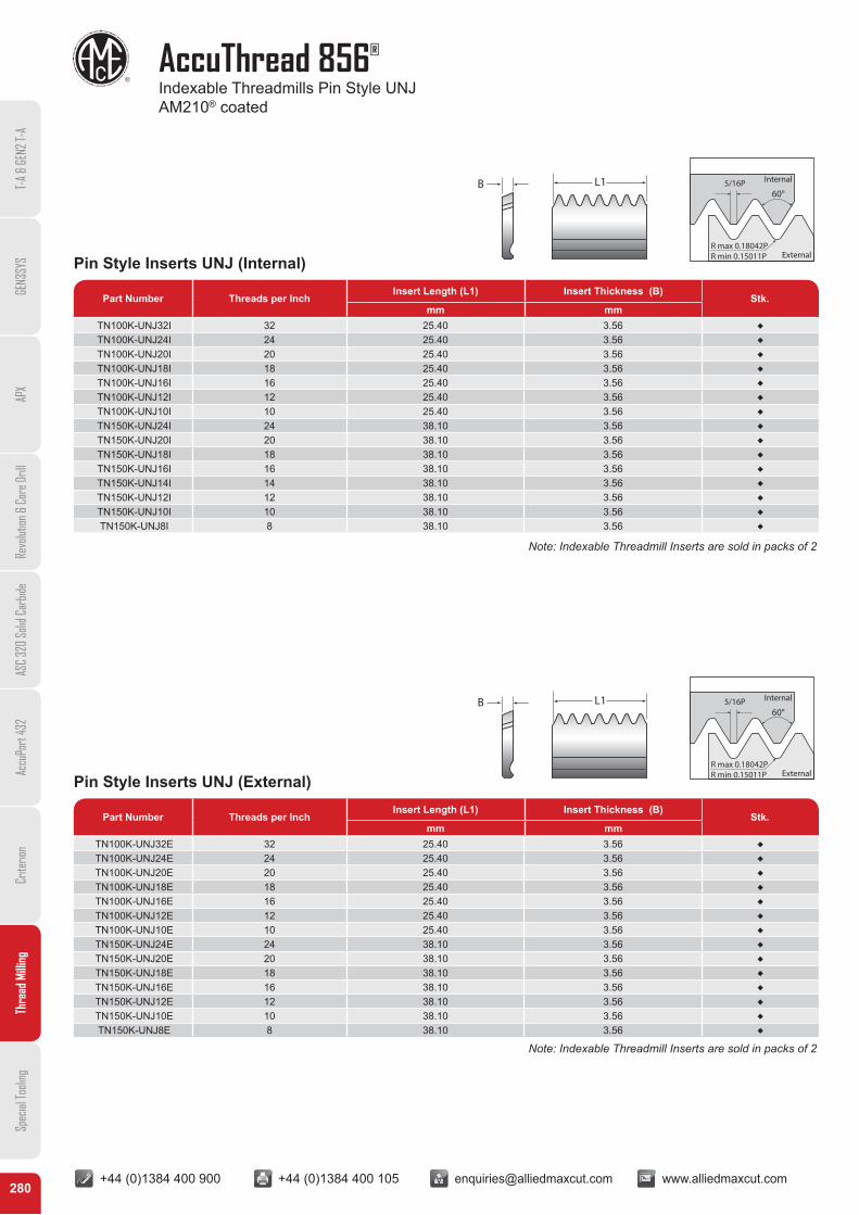
AccuThread 856®
Indexable Threadmills Pin Style UNJ AM210® coated
T-A
& GE
N2 T-
AGE
N3SY
SAP
XRe
volut
ion &
Cor
e Dril
lAS
C 32
0 So
lid C
arbid
eAc
cuPo
rt 43
2Cr
iterio
nTh
read
Milli
ngSp
ecial
Tooli
ng
Pin Style Inserts UNJ (Internal)
Pin Style Inserts UNJ (External)
Part Number Threads per InchInsert Length (L1) Insert Thickness (B)
Stk.mm mm
Part Number Threads per InchInsert Length (L1) Insert Thickness (B)
Stk.mm mm
TN100K-UNJ32I 32 25.40 3.56 R
TN100K-UNJ24I 24 25.40 3.56 R
TN100K-UNJ20I 20 25.40 3.56 R
TN100K-UNJ18I 18 25.40 3.56 R
TN100K-UNJ16I 16 25.40 3.56 R
TN100K-UNJ12I 12 25.40 3.56 R
TN100K-UNJ10I 10 25.40 3.56 R
TN150K-UNJ24I 24 38.10 3.56 R
TN150K-UNJ20I 20 38.10 3.56 R
TN150K-UNJ18I 18 38.10 3.56 R
TN150K-UNJ16I 16 38.10 3.56 R
TN150K-UNJ14I 14 38.10 3.56 R
TN150K-UNJ12I 12 38.10 3.56 R
TN150K-UNJ10I 10 38.10 3.56 R
TN150K-UNJ8I 8 38.10 3.56 R
TN100K-UNJ32E 32 25.40 3.56 R
TN100K-UNJ24E 24 25.40 3.56 R
TN100K-UNJ20E 20 25.40 3.56 R
TN100K-UNJ18E 18 25.40 3.56 R
TN100K-UNJ16E 16 25.40 3.56 R
TN100K-UNJ12E 12 25.40 3.56 R
TN100K-UNJ10E 10 25.40 3.56 R
TN150K-UNJ24E 24 38.10 3.56 R
TN150K-UNJ20E 20 38.10 3.56 R
TN150K-UNJ18E 18 38.10 3.56 R
TN150K-UNJ16E 16 38.10 3.56 R
TN150K-UNJ12E 12 38.10 3.56 R
TN150K-UNJ10E 10 38.10 3.56 R
TN150K-UNJ8E 8 38.10 3.56 R
L1B
L1B
60°5/16P
R max 0.18042PR min 0.15011P External
Internal
60°5/16P
R max 0.18042PR min 0.15011P External
Internal
Note: Indexable Threadmill Inserts are sold in packs of 2
Note: Indexable Threadmill Inserts are sold in packs of 2
+44 (0)1384 400 900 +44 (0)1384 400 105 [email protected] www.alliedmaxcut.com +44 (0)1384 400 900 +44 (0)1384 400 105 [email protected] www.alliedmaxcut.com281
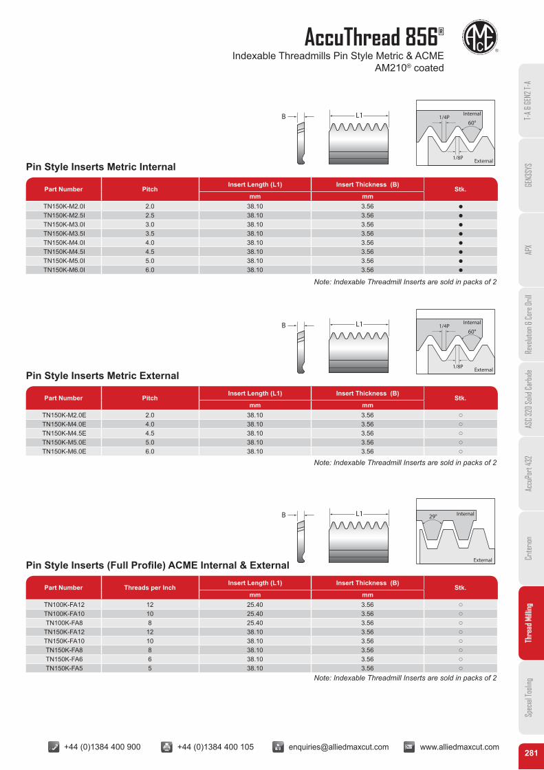
AccuThread 856®
Indexable Threadmills Pin Style Metric & ACME AM210® coated
T-A
& GE
N2 T-
AGE
N3SY
SAP
XRe
volut
ion &
Cor
e Dril
lAS
C 32
0 So
lid C
arbid
eAc
cuPo
rt 43
2Cr
iterio
nTh
read
Milli
ngSp
ecial
Tooli
ng
Part Number Threads per InchInsert Length (L1) Insert Thickness (B)
Stk.mm mm
Part Number Threads per InchInsert Length (L1) Insert Thickness (B)
Stk.mm mm
Pin Style Inserts Metric Internal
Pin Style Inserts Metric External
Pin Style Inserts (Full Profile) ACME Internal & External
Part Number PitchInsert Length (L1) Insert Thickness (B)
Stk.mm mm
Part Number PitchInsert Length (L1) Insert Thickness (B)
Stk.mm mm
Part Number Threads per InchInsert Length (L1) Insert Thickness (B)
Stk.mm mm
TN150K-M2.0I 2.0 38.10 3.56 Q
TN150K-M2.5I 2.5 38.10 3.56 Q
TN150K-M3.0I 3.0 38.10 3.56 Q
TN150K-M3.5I 3.5 38.10 3.56 Q
TN150K-M4.0I 4.0 38.10 3.56 Q
TN150K-M4.5I 4.5 38.10 3.56 Q
TN150K-M5.0I 5.0 38.10 3.56 Q
TN150K-M6.0I 6.0 38.10 3.56 Q
TN150K-M2.0E 2.0 38.10 3.56 p
TN150K-M4.0E 4.0 38.10 3.56 p
TN150K-M4.5E 4.5 38.10 3.56 p
TN150K-M5.0E 5.0 38.10 3.56 p
TN150K-M6.0E 6.0 38.10 3.56 p
TN100K-FA12 12 25.40 3.56 p
TN100K-FA10 10 25.40 3.56 p
TN100K-FA8 8 25.40 3.56 p
TN150K-FA12 12 38.10 3.56 p
TN150K-FA10 10 38.10 3.56 p
TN150K-FA8 8 38.10 3.56 p
TN150K-FA6 6 38.10 3.56 p
TN150K-FA5 5 38.10 3.56 p
L1B
L1B
L1B
60°1/4P
1/8P
Internal
External
60°1/4P
1/8P
Internal
External
29°
External
Internal
Note: Indexable Threadmill Inserts are sold in packs of 2
Note: Indexable Threadmill Inserts are sold in packs of 2
Note: Indexable Threadmill Inserts are sold in packs of 2
+44 (0)1384 400 900 +44 (0)1384 400 105 [email protected] www.alliedmaxcut.com +44 (0)1384 400 900 +44 (0)1384 400 105 [email protected] www.alliedmaxcut.com282
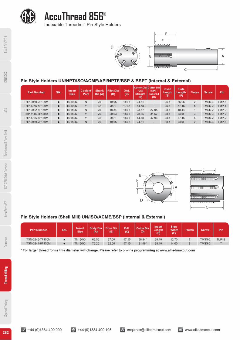
AccuThread 856®
Indexable Threadmill Pin Style Holders
T-A
& GE
N2 T-
AGE
N3SY
SAP
XRe
volut
ion &
Cor
e Dril
lAS
C 32
0 So
lid C
arbid
eAc
cuPo
rt 43
2Cr
iterio
nTh
read
Milli
ngSp
ecial
Tooli
ng
Part Number Stk. Insert Size
Coolant Port
Shank Dia (A)
Pilot Dia (B)
OAL(C)
Cutter Dia (UN)
Straight (D)
Cutter Dia (NPT)
Tapered (D)
Insert Length
(E)
Flute Length
(F)Flutes Screw Pin
THP-0969-2F100M Q TN100K- N 25 19.05 114.3 24.61 - 25.4 35.05 2 TMSS-3 TMP-6 THP-1755-5F100M Q TN100K- Y 32 38.1 101.6 44.58 - 25.4 57.15 5 TMSS-2 TMP-1 THP-0932-1F150M Q TN150K- N 25 18.34 114.3 23.67 27.05 38.1 48.44 1 TMSS-2 TMP-2 THP-1116-3F150M Q TN150K- Y 25 20.63 114.3 28.35 31.67 38.1 50.8 3 TMSS-3 TMP-2 THP-1755-5F150M Q TN150K- Y 32 38.1 114.3 44.58 47.96 38.1 57.15 5 TMSS-2 TMP-2 THP-0969-2F150M Q TN150K- N 25 19.05 114.3 24.61 - 38.1 50.8 2 TMSS-3 TMP-6
Part Number Stk. Insert Size
Body Dia (A)
Bore Dia (B)
OAL(C)
Cutter Dia (D)
Insert Length
(E)
Slow Width
(F)Flutes Screw Pin
TSN-2846-7F150M Q TN150K- 63.50 27.00 57.15 68.94* 38.10 12.70 7 TMSS-2 TMP-2 TSN-3341-8F150M Q TN150K- 76.20 32.00 57.15 81.48* 38.10 14.00 8 TMSS-2 T
Pin Style Holders UN/NPT/ISO/ACME/API/NPTF/BSP & BSPT (Internal & External)
Pin Style Holders (Shell Mill) UN/ISO/ACME/BSP (Internal & External)
D
E
F
C
AB
D
BF
C
E
A
* For larger thread forms this diameter will change. Please refer to on-line programming at www.alliedmaxcut.com

+44 (0)1384 400 900 +44 (0)1384 400 105 [email protected] www.alliedmaxcut.com +44 (0)1384 400 900 +44 (0)1384 400 105 [email protected] www.alliedmaxcut.com283
Technical Section - AccuThread 856®
Recommended Cutting Data Solid Carbide Threadmills
T-A
& GE
N2 T-
AGE
N3SY
SAP
XRe
volut
ion &
Cor
e Dril
lAS
C 32
0 So
lid C
arbid
eAc
cuPo
rt 43
2Cr
iterio
nTh
read
Milli
ngSp
ecial
Tooli
ng
MaterialMaterial
Hardness(BHN)
MaterialMachinability
AM210®
M/min
Cutter (mm)
Recommended Feed (mm/tooth)
3 5 6 8 10 12 16 19
Free Machining Steel
100-150 Easy 274 0.010 0.013 0.018 0.023 0.025 0.038 0.051 0.064150-200 Easy 213 0.010 0.013 0.018 0.023 0.025 0.038 0.051 0.064200-250 Easy 152 0.010 0.013 0.018 0.023 0.025 0.038 0.051 0.064
Low Carbon Steel
85-125 Average 274 0.010 0.013 0.018 0.023 0.025 0.038 0.051 0.064125-175 Average 213 0.010 0.013 0.018 0.023 0.025 0.038 0.051 0.064175-225 Average 183 0.010 0.013 0.018 0.023 0.025 0.038 0.051 0.064225-275 Average 152 0.010 0.013 0.018 0.023 0.025 0.038 0.051 0.064
Medium Carbon Steel
125-175 Average 175 0.010 0.013 0.015 0.020 0.025 0.033 0.046 0.051175-225 Average 152 0.010 0.013 0.015 0.020 0.025 0.033 0.046 0.051225-275 Average 137 0.010 0.013 0.015 0.020 0.025 0.033 0.046 0.051275-325 Average 122 0.010 0.013 0.015 0.020 0.025 0.033 0.046 0.051
Alloy Steel
125-175 Average 175 0.010 0.013 0.015 0.020 0.025 0.033 0.046 0.051175-225 Average 152 0.010 0.013 0.015 0.020 0.025 0.033 0.046 0.051225-275 Average 137 0.010 0.013 0.015 0.020 0.025 0.033 0.046 0.051275-325 Difficult 122 0.010 0.013 0.015 0.020 0.025 0.033 0.046 0.051325-375 Difficult 114 0.010 0.013 0.015 0.020 0.025 0.033 0.046 0.051
High StrengthAlloy Steel
225-300 Average 137 0.010 0.013 0.015 0.020 0.025 0.033 0.046 0.051300-350 Difficult 122 0.010 0.013 0.015 0.020 0.025 0.033 0.046 0.051350-400 Difficult 107 0.010 0.013 0.015 0.020 0.025 0.033 0.046 0.051
Structural Steel100-150 Average 183 0.010 0.013 0.018 0.023 0.025 0.038 0.051 0.064150-250 Average 152 0.010 0.013 0.018 0.023 0.025 0.038 0.051 0.064250-350 Difficult 137 0.010 0.013 0.018 0.023 0.025 0.038 0.051 0.064
Tool Steel150-200 Difficult 175 0.010 0.013 0.018 0.023 0.025 0.038 0.051 0.064200-250 Difficult 152 0.010 0.013 0.018 0.023 0.025 0.038 0.051 0.064
High Temp Alloy140-220 Difficult 37 0.008 0.010 0.015 0.020 0.023 0.025 0.030 0.038220-310 Difficult 27 0.008 0.010 0.015 0.020 0.023 0.025 0.030 0.038
Stainless Steel135-185 Average 160 0.010 0.013 0.015 0.020 0.023 0.025 0.038 0.051185-275 Difficult 152 0.010 0.013 0.015 0.020 0.023 0.025 0.038 0.051
Stainless Steel PH185-275 Average 91 0.010 0.013 0.015 0.020 0.023 0.025 0.038 0.051275-325 Difficult 46 0.010 0.013 0.015 0.020 0.023 0.025 0.038 0.051
Cast Iron
120-150 Easy 206 0.010 0.013 0.018 0.023 0.025 0.038 0.051 0.064150-200 Easy 191 0.010 0.013 0.018 0.023 0.025 0.038 0.051 0.064200-220 Easy 175 0.010 0.013 0.018 0.023 0.025 0.038 0.051 0.064220-260 Average 152 0.010 0.013 0.018 0.023 0.025 0.038 0.051 0.064260-320 Average 145 0.010 0.013 0.018 0.023 0.025 0.038 0.051 0.064
Aluminium, Wrought30 Easy 335 0.013 0.015 0.023 0.025 0.038 0.051 0.064 0.076
180 Easy 305 0.013 0.015 0.023 0.025 0.038 0.051 0.064 0.076Cast Aluminium* 120 Easy 191 0.013 0.015 0.023 0.025 0.038 0.051 0.064 0.076Brass 30-125 Easy 335 0.013 0.015 0.023 0.025 0.038 0.051 0.064 0.076
Formulas: Linear Feed Rate = RPM x mm/tooth x No. of Teeth M/min = (RPM x 3.142 x Dia)/1000. RPM = (M/min x 1000) / (Dia x 3.142)Adjusted Feed Rate (AFR) for Internal Thread Milling = (Thread Major Dia – Cutter Dia) / major Dia) x Linear Feed Rate
The above formula on an internal thread program adjusts the linear feed rate to be applied to the O.D. instead of the centre of the cutting tool. If the feed rate is not adjusted, the excessive feed rate will cause the thread mill cutting edges to fail.Example of an Internal Thread Feed Rate Calculation: Cast Iron 125 BHN with a ½ - 13 thread form.
Note: Reduce feed and speed by 30% for NPT and NPTF Thread Forms due to tapered cutting action * Uncoated thread mills are recommended for cast aluminium applications (price and availability upon request) Refer to recommended pass chart on page 286 when referencing material machinability
Step 1 Step 2 Step 3
RPM=(m/min x 1000)(Dia x 3.142) Linear Feed Rate = RPM x mm/tooth x No of teeth AFR for Internal Thread Milling = (Major Dia-Cutter Dia) / Major Dia) x Linear Feed Rate
RPM=(152 x 1000)(8.89 x 3.142) Linear Feed Rate = 5442 x 0.038 x 4 AFR for Internal Thread Milling = (12.7 – 8.89) / 12.7) x 827.18
RPM=5442 Linear Feed Rate = 827.18 mm/min AFR for Internal Thread Milling = 248.15mm/min
+44 (0)1384 400 900 +44 (0)1384 400 105 [email protected] www.alliedmaxcut.com +44 (0)1384 400 900 +44 (0)1384 400 105 [email protected] www.alliedmaxcut.com284
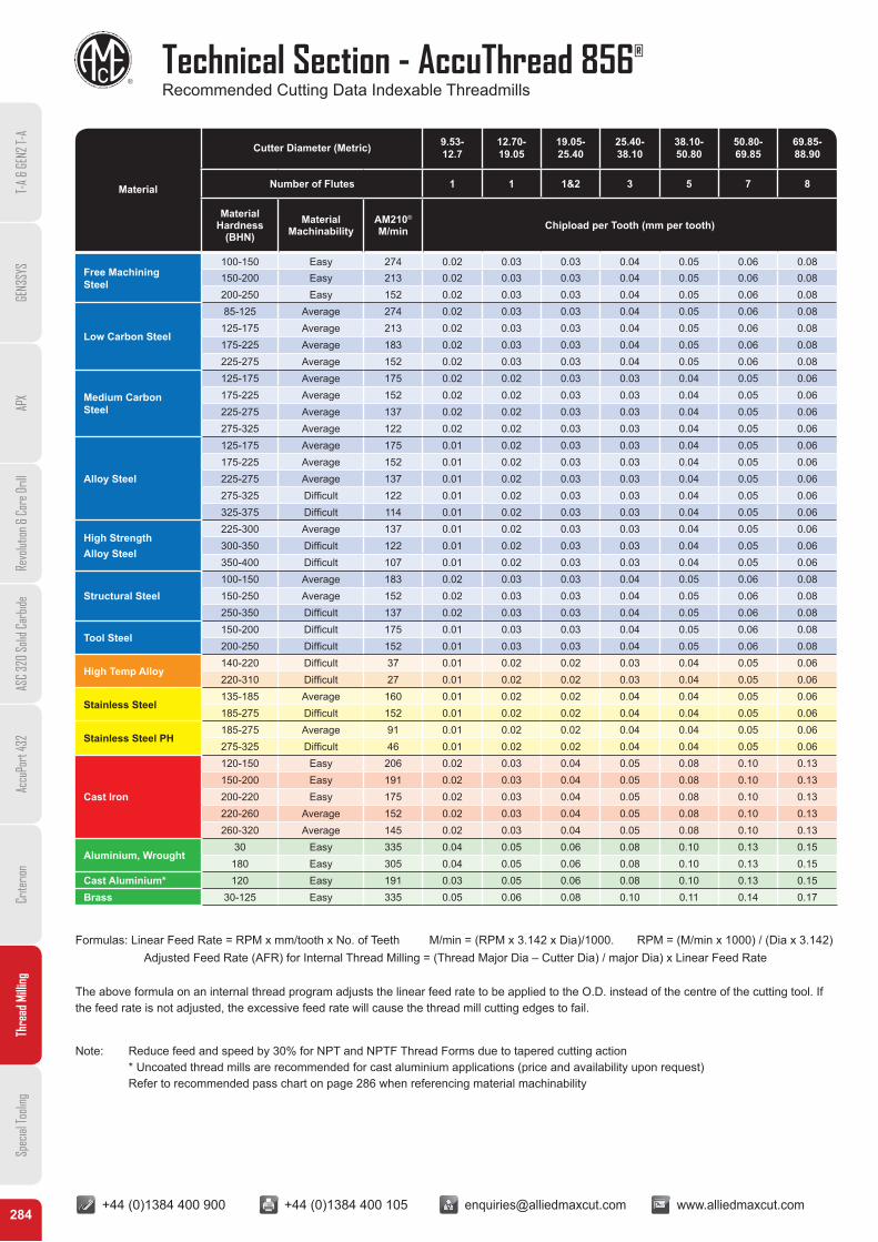
Technical Section - AccuThread 856®
Recommended Cutting Data Indexable Threadmills
T-A
& GE
N2 T-
AGE
N3SY
SAP
XRe
volut
ion &
Cor
e Dril
lAS
C 32
0 So
lid C
arbid
eAc
cuPo
rt 43
2Cr
iterio
nTh
read
Milli
ngSp
ecial
Tooli
ng
Material
Cutter Diameter (Metric) 9.53- 12.7
12.70- 19.05
19.05- 25.40
25.40- 38.10
38.10- 50.80
50.80- 69.85
69.85- 88.90
Number of Flutes 1 1 1&2 3 5 7 8
MaterialHardness
(BHN)Material
MachinabilityAM210®
M/min Chipload per Tooth (mm per tooth)
Free Machining Steel
100-150 Easy 274 0.02 0.03 0.03 0.04 0.05 0.06 0.08150-200 Easy 213 0.02 0.03 0.03 0.04 0.05 0.06 0.08200-250 Easy 152 0.02 0.03 0.03 0.04 0.05 0.06 0.08
Low Carbon Steel
85-125 Average 274 0.02 0.03 0.03 0.04 0.05 0.06 0.08125-175 Average 213 0.02 0.03 0.03 0.04 0.05 0.06 0.08175-225 Average 183 0.02 0.03 0.03 0.04 0.05 0.06 0.08225-275 Average 152 0.02 0.03 0.03 0.04 0.05 0.06 0.08
Medium Carbon Steel
125-175 Average 175 0.02 0.02 0.03 0.03 0.04 0.05 0.06175-225 Average 152 0.02 0.02 0.03 0.03 0.04 0.05 0.06225-275 Average 137 0.02 0.02 0.03 0.03 0.04 0.05 0.06275-325 Average 122 0.02 0.02 0.03 0.03 0.04 0.05 0.06
Alloy Steel
125-175 Average 175 0.01 0.02 0.03 0.03 0.04 0.05 0.06175-225 Average 152 0.01 0.02 0.03 0.03 0.04 0.05 0.06225-275 Average 137 0.01 0.02 0.03 0.03 0.04 0.05 0.06275-325 Difficult 122 0.01 0.02 0.03 0.03 0.04 0.05 0.06325-375 Difficult 114 0.01 0.02 0.03 0.03 0.04 0.05 0.06
High StrengthAlloy Steel
225-300 Average 137 0.01 0.02 0.03 0.03 0.04 0.05 0.06300-350 Difficult 122 0.01 0.02 0.03 0.03 0.04 0.05 0.06350-400 Difficult 107 0.01 0.02 0.03 0.03 0.04 0.05 0.06
Structural Steel100-150 Average 183 0.02 0.03 0.03 0.04 0.05 0.06 0.08150-250 Average 152 0.02 0.03 0.03 0.04 0.05 0.06 0.08250-350 Difficult 137 0.02 0.03 0.03 0.04 0.05 0.06 0.08
Tool Steel150-200 Difficult 175 0.01 0.03 0.03 0.04 0.05 0.06 0.08200-250 Difficult 152 0.01 0.03 0.03 0.04 0.05 0.06 0.08
High Temp Alloy140-220 Difficult 37 0.01 0.02 0.02 0.03 0.04 0.05 0.06220-310 Difficult 27 0.01 0.02 0.02 0.03 0.04 0.05 0.06
Stainless Steel135-185 Average 160 0.01 0.02 0.02 0.04 0.04 0.05 0.06185-275 Difficult 152 0.01 0.02 0.02 0.04 0.04 0.05 0.06
Stainless Steel PH185-275 Average 91 0.01 0.02 0.02 0.04 0.04 0.05 0.06275-325 Difficult 46 0.01 0.02 0.02 0.04 0.04 0.05 0.06
Cast Iron
120-150 Easy 206 0.02 0.03 0.04 0.05 0.08 0.10 0.13150-200 Easy 191 0.02 0.03 0.04 0.05 0.08 0.10 0.13200-220 Easy 175 0.02 0.03 0.04 0.05 0.08 0.10 0.13220-260 Average 152 0.02 0.03 0.04 0.05 0.08 0.10 0.13260-320 Average 145 0.02 0.03 0.04 0.05 0.08 0.10 0.13
Aluminium, Wrought30 Easy 335 0.04 0.05 0.06 0.08 0.10 0.13 0.15
180 Easy 305 0.04 0.05 0.06 0.08 0.10 0.13 0.15Cast Aluminium* 120 Easy 191 0.03 0.05 0.06 0.08 0.10 0.13 0.15Brass 30-125 Easy 335 0.05 0.06 0.08 0.10 0.11 0.14 0.17
Formulas: Linear Feed Rate = RPM x mm/tooth x No. of Teeth M/min = (RPM x 3.142 x Dia)/1000. RPM = (M/min x 1000) / (Dia x 3.142)Adjusted Feed Rate (AFR) for Internal Thread Milling = (Thread Major Dia – Cutter Dia) / major Dia) x Linear Feed Rate
The above formula on an internal thread program adjusts the linear feed rate to be applied to the O.D. instead of the centre of the cutting tool. If the feed rate is not adjusted, the excessive feed rate will cause the thread mill cutting edges to fail.
Note: Reduce feed and speed by 30% for NPT and NPTF Thread Forms due to tapered cutting action * Uncoated thread mills are recommended for cast aluminium applications (price and availability upon request) Refer to recommended pass chart on page 286 when referencing material machinability
+44 (0)1384 400 900 +44 (0)1384 400 105 [email protected] www.alliedmaxcut.com +44 (0)1384 400 900 +44 (0)1384 400 105 [email protected] www.alliedmaxcut.com285
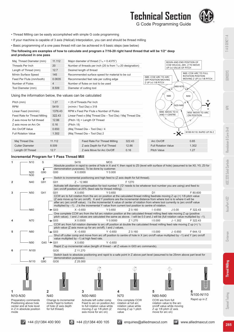
Technical SectionG Code Programming Guide
T-A
& GE
N2 T-
AGE
N3SY
SAP
XRe
volut
ion &
Cor
e Dril
lAS
C 32
0 So
lid C
arbid
eAc
cuPo
rt 43
2Cr
iterio
nTh
read
Milli
ngSp
ecial
Tooli
ng
• Thread Milling can be easily accomplished with simple G code programming
• If your machine is capable of 3 axis (Helical) Interpolation, you can and should be thread milling
• Basic programming of a one pass thread mill can be achieved in 6 basic steps (see below)
The following are examples of how to calculate and program a 7/16-20 right hand thread that will be 1/2“ deep and produced in one pass
Incremental Program for 1 Pass Thread Mill
Using the information below, the values can be calculated
Maj. Thread Diameter (mm) 11.112 Major diameter of thread (7/16 = 0.4375”)Threads Per Inch 20 Number of threads per inch (20 is from 7/16-20 designation)Length of Thread (mm) 12.7 Desired length of threadM/min Surface Speed 145 Recommended surface speed for material to be cutFeed Per Flute (mm/tooth) 0.0635 Recommended feet rate per cutting edgeNumber of Flutes 4 Number of flutes on tool to be usedTool Diameter (mm) 8.509 Diameter of cutting tool
Pitch (mm) 1.27 = 25.4/Threads Per InchRPM 5419 (m/min / Tool Dia) x 318Linear Feed (mm/min) 1376.43 RPM x Feed Per Flute x Number of FlutesFeed Rate for Thread Milling 322.43 Linear Feed x (Maj Thread Dia – Tool Dia) / Maj Thread DiaZ axis move for full thread 12.86 (Pitch / 8) + Length Of ThreadZ axis move on Arc On 0.16 (Pitch / 8)Arc On/Off Value 0.650 (Maj Thread Dia – Tool Dia) / 4Full Rotation Value 1.302 (Maj Thread Dia – Tool Dia) 2
Maj Thread Dia. 11.112Cutter Diameter 8.509Length Of Thread 12.7
Feed Rate For Thread Milling 322.43Z axis Depth for Full Thread 12.86Z axis Move for Arc On/Off 0.16
Arc On/Off 0.65Full Rotation Value 1.302Pitch Value 1.27
N10 5416 MO31
2
3
4
S
N20 G90
G91
G03
G03
G03
G01
GO0
N60 X –0.650
X 0.0000
X –0.650
X 0.650
Z 11.270
Y 0.650
Y 0.0000
Y -0.650
Y -0.650
Z 0.160
Z 1.270
Z 0.160
I -0.650
I 0.000
I 0.000
J 0.00
J -1.302
J -0.650
F 322.43
F 322.43
F 644.12
G41
G40
G00
G01
G01
X 0.0000
Z – 12.860
X 0.650
Y 0.000
F 1270
Y 0.650 D1 F 80.600
N30
N40
N50
N70
5 N80
N90
6 N100
N110
Absolute position in rapid to centre of hole in X and Y, then rapid to Z0 (level with surface of hole) (assumed to be X0, Y0, Z0 for demonstration purposes). To be done by customer.
Activate left diameter compensation for tool number 1 (‘D’ needs to be whatever tool number you are using) and feed to (arc on/off position) at 25% (feed rate for thread milling).
One complete CCW arc from the full arc rotation position at the calculated thread milling feed rate moving Z up (positive pitch value). I and J values are calculated the same as above. I will be 0.0 and J will be (full rotation value multiplied by –1).
CCW arc from full rotation diameter to arc off position at double the calculated thread milling feed rate moving Z up (+) 1/8 pitch value (Z axis move up for arc on/off). I and J values.
Shut off cutter comp and move from arc off position to centre of hole in X (arc on/off value multiplied by –1) and Y (arc on/off value multiplied by –1) at high feed rate.
CCW arc to full rotation from the arc on position at the calculated thread milling feedrate moving Z up (+) 1/8 pitch value (Z axis move up for arc on/off). X and Y positions are the incremental distance from where tool is to where it will be after arc (arc on/off value). I is the incremental X value of center of rotation from where tool currently is (arc on/off value multiplied by –1). J is the incremental Y value from current tool position to centre of rotation.
Switch to incremental positioning and high feed to (Z axis depth for full thread).
Rapid Z up incremental value (length of thread – all Z values in G03 arc commands).
G90 GO0 Z 25.000
Switch back to absolute positioning and rapid to a safe point in Z above part level (assumed to be 25mm above part level for demonstration purposes).
1N10-N30Preparatory commands Positioning above hole center and at hole level in Z in absolute position mode
2N40Change to incremental mode Feed to bottom of hole (Z axis depth for full thread)
3N50-N60Activate left cutter comp Feed to arc on position Arc to full rotation value while moving Z up 1/8 pitch (Z axis move for arc on)
4N70One complete CCW rotation at full arc rotation value while moving Z up 1 pitch value
5N80-N90CCW are from full rotation value to the arc on/off value while moving Z up 1/8 pitch (Z axis move for arc on)
6 N100-N110Rapid up in Z
+44 (0)1384 400 900 +44 (0)1384 400 105 [email protected] www.alliedmaxcut.com +44 (0)1384 400 900 +44 (0)1384 400 105 [email protected] www.alliedmaxcut.com286
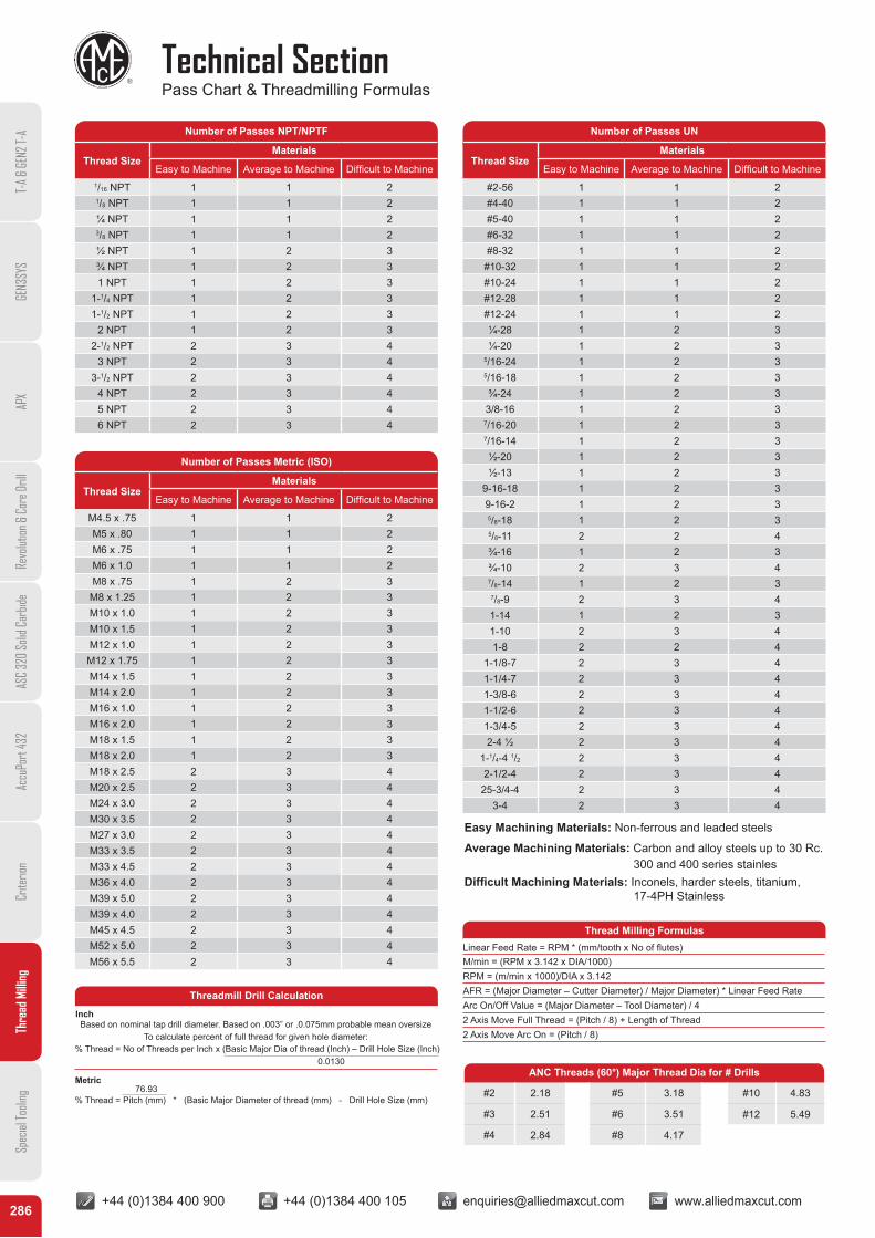
Technical SectionPass Chart & Threadmilling Formulas
T-A
& GE
N2 T-
AGE
N3SY
SAP
XRe
volut
ion &
Cor
e Dril
lAS
C 32
0 So
lid C
arbid
eAc
cuPo
rt 43
2Cr
iterio
nTh
read
Milli
ngSp
ecial
Tooli
ng
Number of Passes NPT/NPTF
Thread SizeMaterials
Easy to Machine Average to Machine Difficult to Machine1/16 NPT 1 1 21/8 NPT 1 1 2¼ NPT 1 1 23/8 NPT 1 1 2½ NPT 1 2 3¾ NPT 1 2 31 NPT 1 2 3
1-1/4 NPT 1 2 31-1/2 NPT 1 2 3
2 NPT 1 2 32-1/2 NPT 2 3 4
3 NPT 2 3 43-1/2 NPT 2 3 4
4 NPT 2 3 45 NPT 2 3 46 NPT 2 3 4
Number of Passes Metric (ISO)
Thread SizeMaterials
Easy to Machine Average to Machine Difficult to Machine
M4.5 x .75 1 1 2M5 x .80 1 1 2M6 x .75 1 1 2M6 x 1.0 1 1 2M8 x .75 1 2 3
M8 x 1.25 1 2 3M10 x 1.0 1 2 3M10 x 1.5 1 2 3M12 x 1.0 1 2 3
M12 x 1.75 1 2 3M14 x 1.5 1 2 3M14 x 2.0 1 2 3M16 x 1.0 1 2 3M16 x 2.0 1 2 3M18 x 1.5 1 2 3M18 x 2.0 1 2 3M18 x 2.5 2 3 4M20 x 2.5 2 3 4M24 x 3.0 2 3 4M30 x 3.5 2 3 4M27 x 3.0 2 3 4M33 x 3.5 2 3 4M33 x 4.5 2 3 4M36 x 4.0 2 3 4M39 x 5.0 2 3 4M39 x 4.0 2 3 4M45 x 4.5 2 3 4M52 x 5.0 2 3 4M56 x 5.5 2 3 4
Number of Passes UN
Thread SizeMaterials
Easy to Machine Average to Machine Difficult to Machine
#2-56 1 1 2#4-40 1 1 2#5-40 1 1 2#6-32 1 1 2#8-32 1 1 2
#10-32 1 1 2#10-24 1 1 2#12-28 1 1 2#12-24 1 1 2¼-28 1 2 3¼-20 1 2 3
5/16-24 1 2 35/16-18 1 2 3¾-24 1 2 3
3/8-16 1 2 37/16-20 1 2 37/16-14 1 2 3½-20 1 2 3½-13 1 2 3
9-16-18 1 2 39-16-2 1 2 35/8-18 1 2 35/8-11 2 2 4¾-16 1 2 3¾-10 2 3 47/8-14 1 2 37/8-9 2 3 41-14 1 2 31-10 2 3 41-8 2 2 4
1-1/8-7 2 3 41-1/4-7 2 3 41-3/8-6 2 3 41-1/2-6 2 3 41-3/4-5 2 3 42-4 ½ 2 3 4
1-1/4-4 1/2 2 3 42-1/2-4 2 3 4
25-3/4-4 2 3 43-4 2 3 4
Threadmill Drill Calculation
InchBased on nominal tap drill diameter. Based on .003” or .0.075mm probable mean oversize
To calculate percent of full thread for given hole diameter:% Thread = No of Threads per Inch x (Basic Major Dia of thread (Inch) – Drill Hole Size (Inch)
0.0130
Metric 76.93% Thread = Pitch (mm) * (Basic Major Diameter of thread (mm) - Drill Hole Size (mm)
Easy Machining Materials: Non-ferrous and leaded steels
Average Machining Materials: Carbon and alloy steels up to 30 Rc. 300 and 400 series stainlesDifficult Machining Materials: Inconels, harder steels, titanium, 17-4PH Stainless
Thread Milling FormulasLinear Feed Rate = RPM * (mm/tooth x No of flutes)M/min = (RPM x 3.142 x DIA/1000)RPM = (m/min x 1000)/DIA x 3.142AFR = (Major Diameter – Cutter Diameter) / Major Diameter) * Linear Feed RateArc On/Off Value = (Major Diameter – Tool Diameter) / 42 Axis Move Full Thread = (Pitch / 8) + Length of Thread2 Axis Move Arc On = (Pitch / 8)
ANC Threads (60°) Major Thread Dia for # Drills
#2 2.18 #5 3.18 #10 4.83
#3 2.51 #6 3.51 #12 5.49
#4 2.84 #8 4.17
+44 (0)1384 400 900 +44 (0)1384 400 105 [email protected] www.alliedmaxcut.com +44 (0)1384 400 900 +44 (0)1384 400 105 [email protected] www.alliedmaxcut.com287
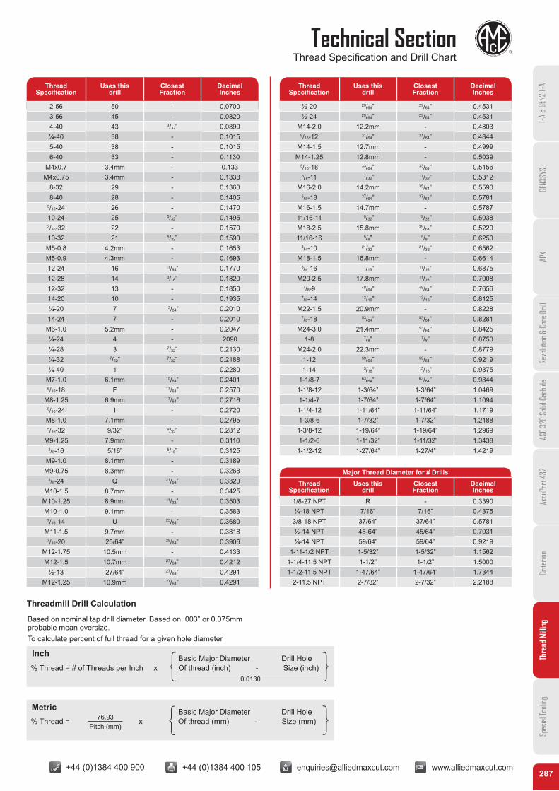
Technical SectionThread Specification and Drill Chart
T-A
& GE
N2 T-
AGE
N3SY
SAP
XRe
volut
ion &
Cor
e Dril
lAS
C 32
0 So
lid C
arbid
eAc
cuPo
rt 43
2Cr
iterio
nTh
read
Milli
ngSp
ecial
Tooli
ng
ThreadSpecification
Uses this drill
Closest Fraction
Decimal Inches
2-56 50 - 0.07003-56 45 - 0.08204-40 43 3/32” 0.0890¼-40 38 - 0.10155-40 38 - 0.10156-40 33 - 0.1130
M4x0.7 3.4mm - 0.133M4x0.75 3.4mm - 0.1338
8-32 29 - 0.13608-40 28 - 0.1405
3/16-24 26 - 0.147010-24 25 5/32” 0.14953/16-32 22 - 0.157010-32 21 5/32” 0.1590M5-0.8 4.2mm - 0.1653M5-0.9 4.3mm - 0.169312-24 16 11/64” 0.177012-28 14 3/16” 0.182012-32 13 - 0.185014-20 10 - 0.1935¼-20 7 13/64” 0.201014-24 7 - 0.2010M6-1.0 5.2mm - 0.2047¼-24 4 - 2090¼-28 3 7/32” 0.2130¼-32 7/32” 7/32” 0.2188¼-40 1 - 0.2280
M7-1.0 6.1mm 15/64” 0.24015/16-18 F 17/64” 0.2570
M8-1.25 6.9mm 17/64” 0.27165/16-24 I - 0.2720M8-1.0 7.1mm - 0.27955/16-32 9/32” 9/32” 0.2812
M9-1.25 7.9mm - 0.31103/8-16 5/16” 5/16” 0.3125
M9-1.0 8.1mm - 0.3189M9-0.75 8.3mm - 0.3268
3/8-24 Q 21/64” 0.3320M10-1.5 8.7mm - 0.3425
M10-1.25 8.9mm 11/32” 0.3503M10-1.0 9.1mm - 0.3583
7/16-14 U 23/64” 0.3680M11-1.5 9.7mm - 0.3818
7/16-20 25/64” 25/64” 0.3906M12-1.75 10.5mm - 0.4133M12-1.5 10.7mm 27/64” 0.4212
½-13 27/64” 27/64” 0.4291M12-1.25 10.9mm 27/64” 0.4291
ThreadSpecification
Uses this drill
Closest Fraction
Decimal Inches
½-20 29/64” 29/64” 0.4531½-24 29/64” 29/64” 0.4531
M14-2.0 12.2mm - 0.48039/16-12 31/64” 31/64” 0.4844
M14-1.5 12.7mm - 0.4999M14-1.25 12.8mm - 0.5039
9/16-18 33/64” 33/64” 0.51565/8-11 17/32” 17/32” 0.5312
M16-2.0 14.2mm 35/64” 0.55905/8-18 37/64” 37/64” 0.5781
M16-1.5 14.7mm - 0.578711/16-11 19/32” 19/32” 0.5938M18-2.5 15.8mm 39/64” 0.522011/16-16 5/8” 5/8” 0.6250
3/4-10 21/32” 21/32” 0.6562M18-1.5 16.8mm - 0.6614
3/4-16 11/16” 11/16” 0.6875M20-2.5 17.8mm 11/16” 0.7008
7/8-9 49/64” 49/64” 0.76567/8-14 13/16” 13/16” 0.8125
M22-1.5 20.9mm - 0.82287/8-18 53/64” 53/64” 0.8281
M24-3.0 21.4mm 53/64” 0.84251-8 7/8” 7/8” 0.8750
M24-2.0 22.3mm - 0.87791-12 59/64” 59/64” 0.92191-14 15/16” 15/16” 0.9375
1-1/8-7 63/64” 63/64” 0.98441-1/8-12 1-3/64” 1-3/64” 1.04691-1/4-7 1-7/64” 1-7/64” 1.1094
1-1/4-12 1-11/64” 1-11/64” 1.17191-3/8-6 1-7/32” 1-7/32” 1.2188
1-3/8-12 1-19/64” 1-19/64” 1.29691-1/2-6 1-11/32” 1-11/32” 1.3438
1-1/2-12 1-27/64” 1-27/4” 1.4219
Major Thread Diameter for # DrillsThread
SpecificationUses this
drillClosest Fraction
Decimal Inches
1/8-27 NPT R - 0.3390¼-18 NPT 7/16” 7/16” 0.4375
3/8-18 NPT 37/64” 37/64” 0.5781½-14 NPT 45-64” 45/64” 0.7031¾-14 NPT 59/64” 59/64” 0.9219
1-11-1/2 NPT 1-5/32” 1-5/32” 1.15621-1/4-11.5 NPT 1-1/2” 1-1/2” 1.50001-1/2-11.5 NPT 1-47/64” 1-47/64” 1.7344
2-11.5 NPT 2-7/32” 2-7/32” 2.2188
Based on nominal tap drill diameter. Based on .003” or 0.075mm probable mean oversize.To calculate percent of full thread for a given hole diameter
% Thread = # of Threads per Inch x Of thread (inch) - Size (inch)
% Thread = x Of thread (mm) - Size (mm)
Basic Major Diameter Drill Hole
Basic Major Diameter Drill Hole
{
{
{
{
0.0130
76.93Pitch (mm)
Threadmill Drill Calculation
Inch
Metric
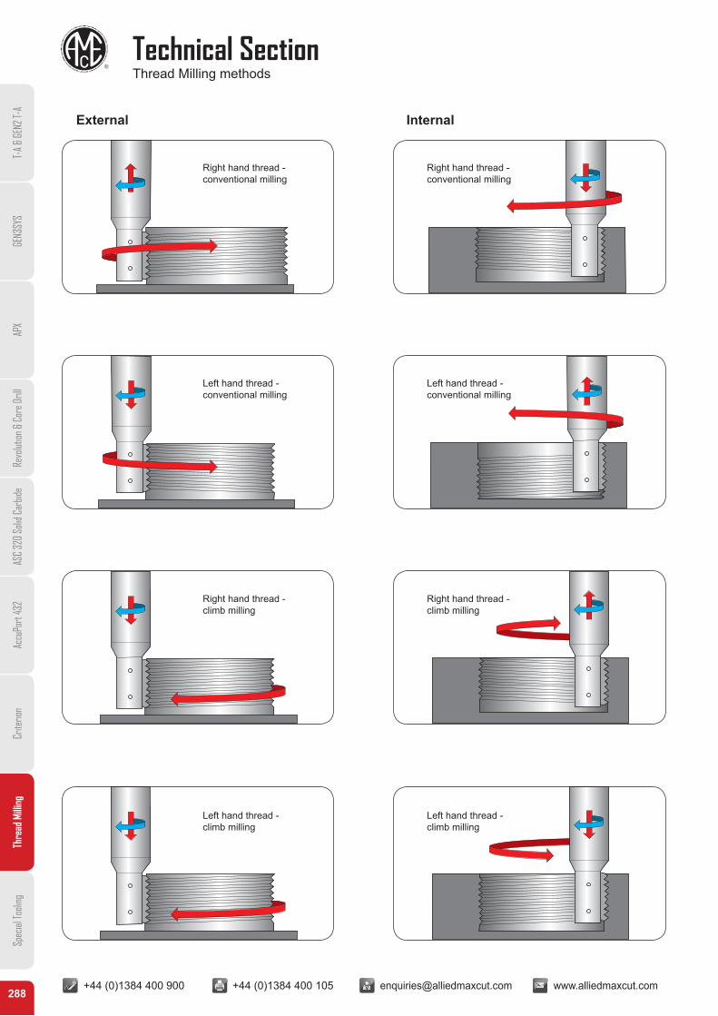
+44 (0)1384 400 900 +44 (0)1384 400 105 [email protected] www.alliedmaxcut.com +44 (0)1384 400 900 +44 (0)1384 400 105 [email protected] www.alliedmaxcut.com288
Technical SectionThread Milling methods
T-A
& GE
N2 T-
AGE
N3SY
SAP
XRe
volut
ion &
Cor
e Dril
lAS
C 32
0 So
lid C
arbid
eAc
cuPo
rt 43
2Cr
iterio
nTh
read
Milli
ngSp
ecial
Tooli
ng
External Internal
Right hand thread -conventional milling
Left hand thread -conventional milling
Right hand thread -climb milling
Left hand thread -climb milling
Right hand thread -conventional milling
Left hand thread -conventional milling
Right hand thread -climb milling
Left hand thread -climb milling
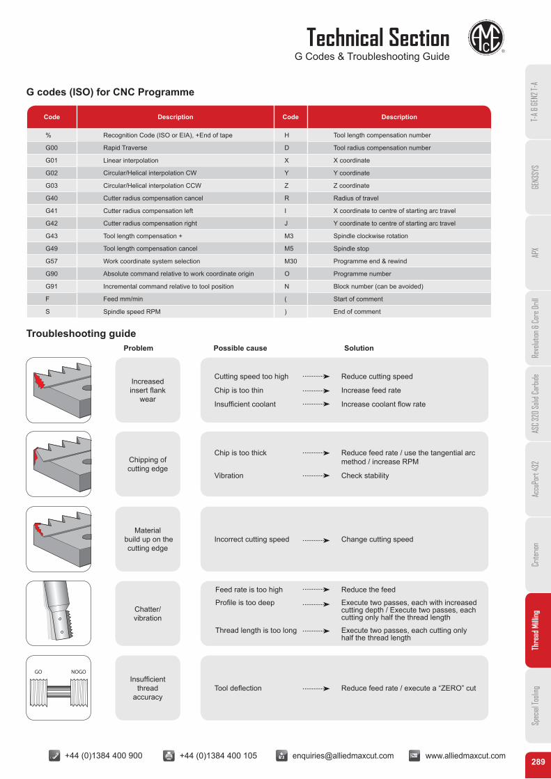
+44 (0)1384 400 900 +44 (0)1384 400 105 [email protected] www.alliedmaxcut.com +44 (0)1384 400 900 +44 (0)1384 400 105 [email protected] www.alliedmaxcut.com289
Technical SectionG Codes & Troubleshooting Guide
T-A
& GE
N2 T-
AGE
N3SY
SAP
XRe
volut
ion &
Cor
e Dril
lAS
C 32
0 So
lid C
arbid
eAc
cuPo
rt 43
2Cr
iterio
nTh
read
Milli
ngSp
ecial
Tooli
ng
G codes (ISO) for CNC Programme
Troubleshooting guideProblem Possible cause Solution
Code Description Code Description
% Recognition Code (ISO or EIA), +End of tape H Tool length compensation number
G00 Rapid Traverse D Tool radius compensation number
G01 Linear interpolation X X coordinate
G02 Circular/Helical interpolation CW Y Y coordinate
G03 Circular/Helical interpolation CCW Z Z coordinate
G40 Cutter radius compensation cancel R Radius of travel
G41 Cutter radius compensation left I X coordinate to centre of starting arc travel
G42 Cutter radius compensation right J Y coordinate to centre of starting arc travel
G43 Tool length compensation + M3 Spindle clockwise rotation
G49 Tool length compensation cancel M5 Spindle stop
G57 Work coordinate system selection M30 Programme end & rewind
G90 Absolute command relative to work coordinate origin O Programme number
G91 Incremental command relative to tool position N Block number (can be avoided)
F Feed mm/min ( Start of comment
S Spindle speed RPM ) End of comment
Increased insert flank
wear
Cutting speed too high Reduce cutting speed
Chip is too thin Increase feed rate
Insufficient coolant Increase coolant flow rate
Chip is too thick Reduce feed rate / use the tangential arc method / increase RPM
Vibration Check stability
Incorrect cutting speed Change cutting speed
Feed rate is too high Reduce the feed
Profile is too deep Execute two passes, each with increased cutting depth / Execute two passes, each cutting only half the thread length
Thread length is too long Execute two passes, each cutting only half the thread length
Tool deflection Reduce feed rate / execute a “ZERO” cut
Chipping of cutting edge
Material build up on the
cutting edge
Chatter/ vibration
GO NOGOInsufficient
thread accuracy
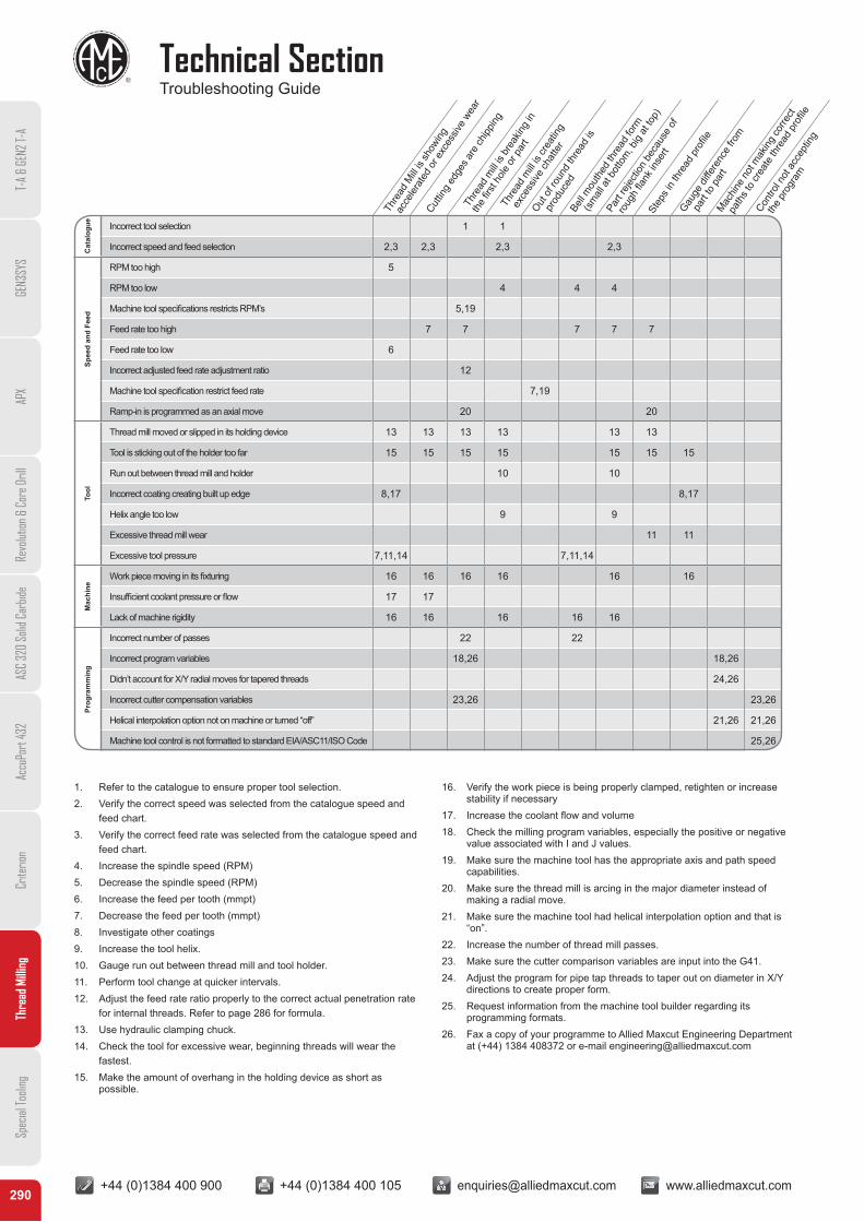
+44 (0)1384 400 900 +44 (0)1384 400 105 [email protected] www.alliedmaxcut.com +44 (0)1384 400 900 +44 (0)1384 400 105 [email protected] www.alliedmaxcut.com290
Technical SectionTroubleshooting Guide
T-A
& GE
N2 T-
AGE
N3SY
SAP
XRe
volut
ion &
Cor
e Dril
lAS
C 32
0 So
lid C
arbid
eAc
cuPo
rt 43
2Cr
iterio
nTh
read
Milli
ngSp
ecial
Tooli
ng
Thre
ad M
ill is
show
ing
acc
elera
ted
or e
xces
sive
wear
Cuttin
g ed
ges a
re ch
ipping
Thre
ad m
ill is
brea
king
in
the
first
hole
or p
art
Thre
ad m
ill is
crea
ting
exc
essiv
e ch
atte
r
Out o
f rou
nd th
read
is
pr
oduc
edBe
ll mou
thed
thre
ad fo
rm
(s
mall
at b
otto
m, b
ig at
top)
Part
rejec
tion
beca
use
of
rou
gh fla
nk in
sert
Contro
l not
acc
eptin
g
the
pro
gram
Mac
hine
not m
aking
corre
ct
pat
hs to
crea
te th
read
pro
file
Gauge
diffe
renc
e fro
m
pa
rt to
par
t
Step
s in
thre
ad p
rofile
Cat
alog
ue Incorrect tool selection 1 1
Incorrect speed and feed selection 2,3 2,3 2,3 2,3
Spee
d an
d Fe
ed
RPM too high 5
RPM too low 4 4 4
Machine tool specifications restricts RPM’s 5,19
Feed rate too high 7 7 7 7 7
Feed rate too low 6
Incorrect adjusted feed rate adjustment ratio 12
Machine tool specification restrict feed rate 7,19
Ramp-in is programmed as an axial move 20 20
Tool
Thread mill moved or slipped in its holding device 13 13 13 13 13 13
Tool is sticking out of the holder too far 15 15 15 15 15 15 15
Run out between thread mill and holder 10 10
Incorrect coating creating built up edge 8,17 8,17
Helix angle too low 9 9
Excessive thread mill wear 11 11
Excessive tool pressure 7,11,14 7,11,14
Mac
hine
Work piece moving in its fixturing 16 16 16 16 16 16
Insufficient coolant pressure or flow 17 17
Lack of machine rigidity 16 16 16 16 16
Prog
ram
min
g
Incorrect number of passes 22 22
Incorrect program variables 18,26 18,26
Didn’t account for X/Y radial moves for tapered threads 24,26
Incorrect cutter compensation variables 23,26 23,26
Helical interpolation option not on machine or turned “off” 21,26 21,26
Machine tool control is not formatted to standard EIA/ASC11/ISO Code 25,26
1. Refer to the catalogue to ensure proper tool selection.2. Verify the correct speed was selected from the catalogue speed and
feed chart.3. Verify the correct feed rate was selected from the catalogue speed and
feed chart.4. Increase the spindle speed (RPM)5. Decrease the spindle speed (RPM)6. Increase the feed per tooth (mmpt)7. Decrease the feed per tooth (mmpt)8. Investigate other coatings9. Increase the tool helix.10. Gauge run out between thread mill and tool holder.11. Perform tool change at quicker intervals.12. Adjust the feed rate ratio properly to the correct actual penetration rate
for internal threads. Refer to page 286 for formula.13. Use hydraulic clamping chuck.14. Check the tool for excessive wear, beginning threads will wear the
fastest.15. Make the amount of overhang in the holding device as short as
possible.
16. Verify the work piece is being properly clamped, retighten or increase stability if necessary
17. Increase the coolant flow and volume18. Check the milling program variables, especially the positive or negative
value associated with I and J values.19. Make sure the machine tool has the appropriate axis and path speed
capabilities.20. Make sure the thread mill is arcing in the major diameter instead of
making a radial move.21. Make sure the machine tool had helical interpolation option and that is
“on”.22. Increase the number of thread mill passes.23. Make sure the cutter comparison variables are input into the G41.24. Adjust the program for pipe tap threads to taper out on diameter in X/Y
directions to create proper form.25. Request information from the machine tool builder regarding its
programming formats.26. Fax a copy of your programme to Allied Maxcut Engineering Department
at (+44) 1384 408372 or e-mail [email protected]