T-A & GEN2 T-A Technical - Allied Maxcut · T-A & GEN2 T-A GEN3SYS APX Revolution & Core Drill ASC...
6
T-A & GEN2 T-A GEN3SYS APX Revolution & Core Drill ASC 320 Solid Carbide AccuPort 432 Criterion Thread Milling Special Tooling 255 +44 (0)1384 400 900 +44 (0)1384 400 105 [email protected] www.alliedmaxcut.com Technical CONTENTS Page Set-up Instructions 256 Recommended Speeds & Feeds 260 Guaranteed Application Request Form 299
-
Upload
nguyenmien -
Category
Documents
-
view
220 -
download
0
Transcript of T-A & GEN2 T-A Technical - Allied Maxcut · T-A & GEN2 T-A GEN3SYS APX Revolution & Core Drill ASC...

T-A
& GE
N2 T-
AGE
N3SY
SAP
XRe
volut
ion &
Cor
e Dril
lAS
C 32
0 So
lid C
arbid
eAc
cuPo
rt 43
2Cr
iterio
nTh
read
Milli
ngSp
ecial
Tooli
ng
255+44 (0)1384 400 900 +44 (0)1384 400 105 [email protected] www.alliedmaxcut.com
Technical
CONTENTS Page
Set-up Instructions 256
Recommended Speeds & Feeds 260
Guaranteed Application Request Form 299

T-A
& GE
N2 T-
AGE
N3SY
SAP
XRe
volut
ion &
Cor
e Dril
lAS
C 32
0 So
lid C
arbid
eAc
cuPo
rt 43
2Cr
iterio
nTh
read
Milli
ngSp
ecial
Tooli
ng
256
General Boring Head Information
Allied Criterion Boring Heads have three major components: the boring head body (#2), bar holder/insert holder (#1), and dial screw (#3).
The boring head body (#2) has a black oxide finish for rust prevention. The bar holder or insert holder (#1) has been satin chromed for wear resistance. The dial screw (#3) has been precision ground to give accurate movement of the bar holder/insert holder in the dove tail slide.
The gib tension has been preset at the factory. The two gib screws (#5) should not be loosened to make size adjustments. These screws are for adjusting the gib pressure only and are filled with red wax to prevent accidental adjustment.
The locking screw (#6) is the only screw that needs to be loosened to make size changes to the boring head.
1
2
3
4
5
6
5
1. Bar/Insert Holder2. Boring Head Body3. Dial Screw4. Bar Holder Set Screws5. Gib Screws6. Locking Screw
Diameter Adjustment
Adjusting Standard Boring Heads (see figure above)
Adjusting Micro Adjusting Setting Boring Heads
To adjust the diameter of a Allied Criterion standard boring head: 1. Loosen the locking screw (#6) 2. Turn the dial screw (#3) clockwise to increase the diameter and counterclockwise to decrease the diameter 3. Tighten the locking screw (#6)
IMPORTANT: Do not loosen the gib screws (#5). It can cause poor performance when making diameter adjustments.
NOTE: To machine a smaller bore diameter, turn dial screw (3) counter-clockwise one full turn minimum to remove any backlash and then adjust to smaller size.
Adjusting micro adjusting setting boring heads is just as easy as adjusting standard boring heads. First, you adjust your boring head using the 0.025mm adjustment (#3) and you make your final adjustment with the 0.0012mm adjustment (#7). 1. Loosen the lock screw (#6) 2. Turn the dial screw (#3) clockwise to increase the diameter and counterclockwise to decrease the diameter 3. Tighten the lock screw (#6) 4. Turn the 0.0012mm dial screw (#7) clockwise to increase the
diameter and counterclockwise to decrease the diameter. No locking of the 0.0012mm dial screw (#7) is required.
NOTE: The micro adjusting boring heads only have a total range of 0.150mm on diameter.
5
2
3
6
5
71
1. Bar/Insert Holder2. Boring Head Body3. Dial Screw4. Bar Holder Set Screws5. Gib Screws6. Locking Screw7. Micro Adjusting Dial Screw
+44 (0)1384 400 900 +44 (0)1384 400 105 [email protected] www.alliedmaxcut.com
Set-up InstructionsGeneral Information

T-A
& GE
N2 T-
AGE
N3SY
SAP
XRe
volut
ion &
Cor
e Dril
lAS
C 32
0 So
lid C
arbid
eAc
cuPo
rt 43
2Cr
iterio
nTh
read
Milli
ngSp
ecial
Tooli
ng
257
Set-up InstructionsCri-Twin®
+44 (0)1384 400 900 +44 (0)1384 400 105 [email protected] www.alliedmaxcut.com
Cri-Twin® Modular Boring Heads
1. Loosen the insert holder lock screw (#4) on the insert holder to be adjusted and re-snug lightly, using light finger pressure only. Only one insert holder should be adjusted at a time. The other insert holder should remain locked. 2. Loosen and re-snug the body clamp bolt (#5) so a small
amount of tension is felt when adjusting the dial screw. 3. Turn dial screw (#3) clockwise to increase the diameter and counter-clockwise to decrease the diameter. 4. Tighten the insert holder locking screw (#4). 5. Rotate the boring head 180°. 6. Repeat steps 1, 3, and 4. 7. Tighten the body clamp bolt (#5).
NOTE: To machine a smaller bore diameter, turn dial screw (3) counter-clockwise one full turn minimum to remove any backlash and then adjust to smaller size.
Procedure for Adjusting Cri-Twin® Modular Boring Heads
5
2
4
3
1
1. Insert Holders2. Boring Head Body3. Dial Screw4. Insert Holder Locking Screw5. Body Clamp Bolt
• Double Feed Rate Operations: This requires using two “standard length” or two
“zero lead” insert holders and setting the cutting tips of both insert holders to bore the same diameter. The inserts will make equal cuts in the bore so you can double your feed rate and reduce the cycle time to bore your hole. Utilizing the Cri-Twin® System in this manner may leave tool retraction marks in the finish bore. For best results, you should bore into and out of the hole.
• Double Material Removed: This requires using a standard and a short length insert
holder. The standard length insert holder enters the cut first so it needs to be set to remove one-half of the material to be bored from the hole. The short insert holder is then set to the finish bore diameter. Remember, when doubling the material removed, each cutting edge is working separately, and you should not double your feed rate.
NOTICE: Use finish boring feed recommendations from Speeds & Feeds chart on page 260.
• Roughing and Finishing: This requires using a standard and a short length insert
holder. The standard length insert holder will be set to the rough bore diameter and then the short length insert holder will be set to the finish bore diameter. Utilizing the Cri-Twin® System in this manner may leave tool retraction marks in the finish bore. For best results, you will want to consider boring into and out of the hole.
NOTICE: Use finish boring feed recommendations from Speeds & Feeds chart on page 260.
The Cri-Twin® Modular Boring System is one of the most versatile boring systems available today. You can, with a combination of insert holders, perform different types of boring operations. The Cri-Twin® System can double your feed rate, double the material removed, or rough and finish in the same operation.
NOTICE: Use rough boring feed recommendations from Speeds & Feeds chart on page 260.
T-A
& GE
N2 T-
AGE
N3SY
SAP
XRe
volut
ion &
Cor
e Dril
lAS
C 32
0 So
lid C
arbid
eAc
cuPo
rt 43
2Cr
iterio
nTh
read
Milli
ngSp
ecial
Tooli
ng
258
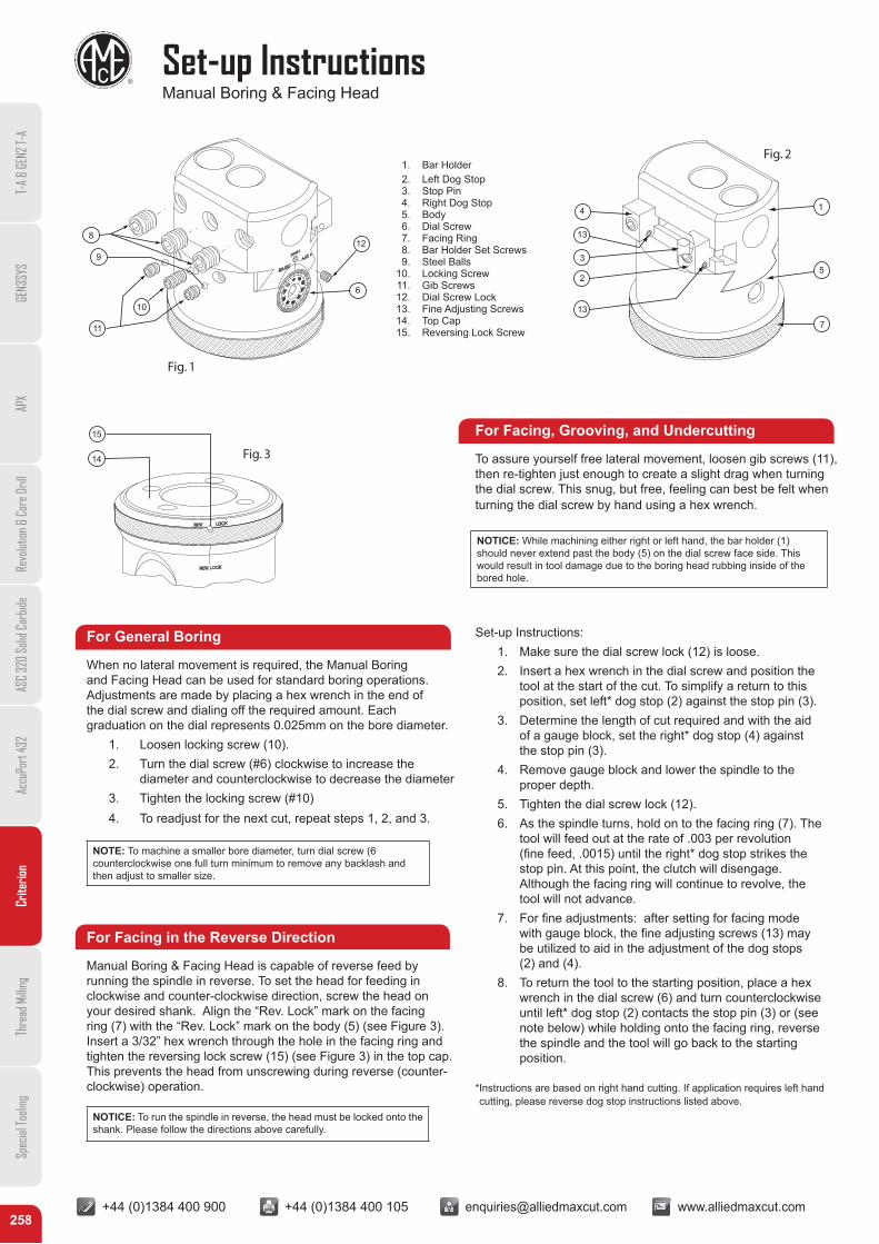
Set-up InstructionsManual Boring & Facing Head
Fig. 2
Fig. 3
Fig. 1
1. Bar Holder2. Left Dog Stop3. Stop Pin4. Right Dog Stop5. Body6. Dial Screw7. Facing Ring8. Bar Holder Set Screws9. Steel Balls
10. Locking Screw11. Gib Screws12. Dial Screw Lock13. Fine Adjusting Screws14. Top Cap15. Reversing Lock Screw
8
9
10
11
12
6
1
13
4
3
2
13
7
5
Fig. 2
Fig. 3
15
14
For General Boring
When no lateral movement is required, the Manual Boring and Facing Head can be used for standard boring operations. Adjustments are made by placing a hex wrench in the end of the dial screw and dialing off the required amount. Each graduation on the dial represents 0.025mm on the bore diameter. 1. Loosen locking screw (10). 2. Turn the dial screw (#6) clockwise to increase the diameter and counterclockwise to decrease the diameter 3. Tighten the locking screw (#10) 4. To readjust for the next cut, repeat steps 1, 2, and 3.
For Facing in the Reverse Direction
Manual Boring & Facing Head is capable of reverse feed by running the spindle in reverse. To set the head for feeding in clockwise and counter-clockwise direction, screw the head on your desired shank. Align the “Rev. Lock” mark on the facing ring (7) with the “Rev. Lock” mark on the body (5) (see Figure 3). Insert a 3/32” hex wrench through the hole in the facing ring and tighten the reversing lock screw (15) (see Figure 3) in the top cap. This prevents the head from unscrewing during reverse (counter-clockwise) operation.
For Facing, Grooving, and Undercutting
To assure yourself free lateral movement, loosen gib screws (11), then re-tighten just enough to create a slight drag when turning the dial screw. This snug, but free, feeling can best be felt when turning the dial screw by hand using a hex wrench.
Set-up Instructions: 1. Make sure the dial screw lock (12) is loose. 2. Insert a hex wrench in the dial screw and position the tool at the start of the cut. To simplify a return to this position, set left* dog stop (2) against the stop pin (3). 3. Determine the length of cut required and with the aid of a gauge block, set the right* dog stop (4) against the stop pin (3). 4. Remove gauge block and lower the spindle to the proper depth. 5. Tighten the dial screw lock (12). 6. As the spindle turns, hold on to the facing ring (7). The tool will feed out at the rate of .003 per revolution (fine feed, .0015) until the right* dog stop strikes the stop pin. At this point, the clutch will disengage. Although the facing ring will continue to revolve, the tool will not advance. 7. For fine adjustments: after setting for facing mode with gauge block, the fine adjusting screws (13) may be utilized to aid in the adjustment of the dog stops (2) and (4). 8. To return the tool to the starting position, place a hex wrench in the dial screw (6) and turn counterclockwise until left* dog stop (2) contacts the stop pin (3) or (see note below) while holding onto the facing ring, reverse the spindle and the tool will go back to the starting position.
* Instructions are based on right hand cutting. If application requires left hand cutting, please reverse dog stop instructions listed above.
NOTE: To machine a smaller bore diameter, turn dial screw (6 counterclockwise one full turn minimum to remove any backlash and then adjust to smaller size.
NOTICE: To run the spindle in reverse, the head must be locked onto the shank. Please follow the directions above carefully.
NOTICE: While machining either right or left hand, the bar holder (1) should never extend past the body (5) on the dial screw face side. This would result in tool damage due to the boring head rubbing inside of the bored hole.
+44 (0)1384 400 900 +44 (0)1384 400 105 [email protected] www.alliedmaxcut.com

T-A
& GE
N2 T-
AGE
N3SY
SAP
XRe
volut
ion &
Cor
e Dril
lAS
C 32
0 So
lid C
arbid
eAc
cuPo
rt 43
2Cr
iterio
nTh
read
Milli
ngSp
ecial
Tooli
ng
259
Set-up InstructionsManual Boring & Facing Head
+44 (0)1384 400 900 +44 (0)1384 400 105 [email protected] www.alliedmaxcut.com
For CNC Operations, Horizontal or Vertical
To set the head for CNC tool change operations, first refer to the “For Facing, Grooving, and Undercutting” and “For Facing in the Reverse Direction” instructions on page 258 and set the gib, stop dogs, and thread lock as described.
Install the head in the machine spindle and ensure the spindle is in its “home” or “tool change” position. Take note of the position of the anti-rotation device on your machine in relation to the key slot in the taper shank. Remove the head from the machine. Using the two #10-32 cap screws supplied, attach the plunger housing (16) to the facing ring (7). Note that the lock ring (18) should be loose and turn freely. Align the 1/8” dowel pin in the plunger with the slot in the lock ring. Attach the stop arm (19) to the plunger (17) using the #10-32 button head screw provided. At this time, the facing ring should turn with slight resistance. Rotate the facing ring so that the stop arm is in the approximate position relative to the key slot in the taper shank, noted previously.
Install the head in the spindle, taking care to set the stop arm in its proper position relative to the anti-rotation device on your machine.
With the head in the machine’s spindle at its “home” or “tool change” position, clamp the lock ring (20) in position using the two #4-40 set screws on the periphery of the lock ring. The head is now ready for use.
(D/0.038) / (RPM/60) = T
WHERE:• RPM is the spindle speed• 60 = seconds• D is the distance from the dog stop to the stop pin• 0.038mm = radial feed per revolution• T is the dwell time in seconds
EXAMPLE:The cut is 12.7mm change in diameter. The radial distance (the distance the dog stop is away from the stop pin) is 6.35mm. This is your D. The spindle speed is determined to be 500 RPM. Therefore, the formula is now:
(6.35/0.038) / (500/60) = T 20 seconds = T
As a matter of practice, the dwell time will almost always be a few seconds longer than “T” to allow the head to come firmly against the stop and force the clutch to slip. This will allow the tool to come to a constant size (spring cut). This may take some test cuts to determine the necessary additional time.
Use the information above to face a bottom bore and cut an internal relief groove. Call up the head in the CNC program. DO NOT START THE SPINDLE. Center the head over the bore to enter. Enter the holder in Z axis so that the groove tool is properly placed to begin cutting. In the program, set the RPM to be 500 as calculated from example. NOW START THE SPINDLE and set a dwell time of, say, 22 seconds. At the end of this dwell, stop the spindle and set another dwell time of 22 seconds. At the end of this dwell, stop the spindle and retract the head. You now have a faced surface with an undercut.
If the tool is free of cutting on the return stroke, the head may be increased to the maximum of 700 RPM to speed the return as long as the dwell time is reduced accordingly so as not to slip the clutch unnecessarily. Excessive dwell time has the effect of “impact hammering” the feed mechanism against the dog stop and should be avoided.IMPORTANT: Stop arm is required.
NOTICE: Damage to the Boring & Facing Head’s clutch and gear mechanism may result if operated above 700 RPM. Because the head is not connected to, or controlled by, the machine’s CNC control, allowances must be made in the machine’s program to allow the head enough time to make its cut (and return). To accomplish this, a dwell must be inserted in the program. To calculate the dwell time, use the following formula.
20
18
19
17
16
1/8" Dowel Pin
10-32 Cap Screw
10-32 Cap Screw
10-32 Button Head Screw
7

T-A
& GE
N2 T-
AGE
N3SY
SAP
XRe
volut
ion &
Cor
e Dril
lAS
C 32
0 So
lid C
arbid
eAc
cuPo
rt 43
2Cr
iterio
nTh
read
Milli
ngSp
ecial
Tooli
ng
260
Recommended Speeds & FeedsMetric
IMPORTANT: The speeds and feeds below are a general starting point for all applications. Factory technical assistance is available through our Application Engineering department.
MaterialHardness
Finish Boring (Cri-Bore, CB, CBER) Rough Boring (Cri-Twin®) *Speed
FeedSpeed
Feed(BHN) kg N/mm2
Uncoated TiN Uncoated TiNM/min mm/rev M/min mm/rev
Free Machining Steel 100 - 250 38 - 88 370 - 870 107 - 213 137 - 244 .076 - .127 137 - 244 137 - 305 .152 - .406
Low Carbon Steel 85 - 275 30 - 96 300 - 940 107 - 213 137 - 244 .051 - .102 137 - 244 137 - 305 .152 - .406
Medium Carbon Steel 125 -325 46 - 111 450 - 1090 122 - 213 152- 244 .051 - .102 137 - 244 137 - 305 .152 - .406
Alloy Steel 125 - 375 46 - 129 450 - 1265 91 - 182 122 - 213 .051 - .102 137 - 244 137 - 305 .152 - .406
High Strength Alloy 225 - 400 77 - 139 600 - 1365 91 - 182 107 - 198 .051 - .102 122 - 213 137 - 244 .152 - .406
Tool Steel 150 - 250 50 - 88 500 - 870 91 - 182 107 - 213 .051 - .102 122 - 213 122 - 213 .152 - .254
High Temp Alloy 140 - 310 49 - 101 480 - 990 30 - 76 46 - 91 .051 - .102 30 - 76 46 - 91 .152 - .254
Stainless Steel 400 Series416, 420 185 - 350 65 - 121 640 - 1180 107 - 182 122 - 198 .051 - .102 122 - 182 122 - 213 .152 - .305
Stainless Steel 300 Series304, 316, 17-4PH 135 - 275 49 - 96 480 - 940 107 - 182 122 - 198 .051 - .102 122 - 182 122 - 213 .152 - .305
Super Duplex Stainless Steel 135 - 275 49 - 96 480 - 940 107 - 182 122 - 198 .051 - .102 122 - 182 122 - 213 .152 - .305
Nodular, Grey, Ductile Cast Iron 120 - 320 44 - 104 430 - 1020 122-182 152 - 213 .051 - .102 122 - 182 152 - 213 .152 - .305
Cast Aluminum 30 - 180 10 - 62 100 - 600 229 - 305 244- 335 .051 - .102 229 - 305 244- 335 .152 - .406
Wrought Aluminum 30 - 180 10 - 62 100 - 600 229 - 305 229 - 305 .051 - .102 229 - 305 229 - 305 .152 - .406
Brass 100 38 370 213 - 290 229 - 305 .051 - .102 213 - 290 229 - 305 .152 - .406
*See page 257 for instructions on applying Cri-Twin® boring head in different configurations
NOTICE: The modular boring system’s configuration, including the length of boring bar, boring head off set, and amount of extensions and/or reducers may all affect performance of boring systems. All of these factors may increase imbalance of the modular boring system. Imbalance at excessive RPM will cause vibration in the machine tool, which can cause damage to the machine tool; in particular the spindle. This vibration may occur at spindle speeds above 1000 RPM. If vibration is present, reduce spindle speed.