T-A & GEN2 T-A GEN3SYS - Allied · PDF fileThe APX Drill is a high performance modular system...
32
+44 (0)1384 400 900 +44 (0)1384 400 105 [email protected] www.alliedmaxcut.com 147 • Drilling range 38.00mm to 101.60mm • Depths 3, 5, 8 and 10 x D • AMEC ® proprietary IC inserts use AM300 ® coating for maximum performance • Multiple pilot geometry choices from T-A ® , GEN2 ® , GEN3SYS ® or GEN3SYS ® XT programmes offering greater flexibility • Interchangeable heads allow each holder to cover a range of diameters reducing tool inventory Features and Benefits The APX Drill is a high performance modular system for large diameter holes and is designed to run at high speeds, maximising the power curves of modern CNC equipment. CONTENTS APX Drill Page 148 Pilot Insert Information Page 150 IC Insert Information Page 152 How to identify information Page 153 38 Series Heads 38 Series Holders Page 154 Page 155 44 Series Heads 44 Series Holders Page 156 Page 157 51 Series Heads 51 Series Holders Page 158 Page 159 57 Series Heads 57 Series Holders Page 160 Page 161 63 Series Heads 63 Series Holders Page 162 Page 163 70 Series Heads 70 Series Holders Page 164 Page 165 76 Series Heads 76 Series Holders Page 166 Page 167 83 Series Heads 83 Series Holders Page 168 Page 169 89 Series Heads 89 Series Holders Page 170 Page 171 95 Series Heads 95 Series Holders Page 172 Page 173 Assembly Details Page 174 Technical Section Page 175 Holder Accessories Page 178 Guaranteed Application Request Form Page 299 38.00 to 43.99mm 44.00 to 50.99mm 51.00 to 56.99mm 57.00 to 62.99mm 63.00 to 69.99mm 70.00 to 75.99mm 76.00 to 82.99mm 83.00 to 88.99mm 89.00 to 94.99mm 95.00 to 101.60mm T-A & GEN2 T-A GEN3SYS APX Revolution & Core Drill ASC 320 Solid Carbide AccuPort 432 Criterion Thread Milling Special Tooling
Transcript of T-A & GEN2 T-A GEN3SYS - Allied · PDF fileThe APX Drill is a high performance modular system...

+44 (0)1384 400 900 +44 (0)1384 400 105 [email protected] www.alliedmaxcut.com +44 (0)1384 400 900 +44 (0)1384 400 105 [email protected] www.alliedmaxcut.com147
• Drilling range 38.00mm to 101.60mm
• Depths 3, 5, 8 and 10 x D
• AMEC® proprietary IC inserts use AM300® coating for maximum performance
• Multiple pilot geometry choices from T-A®, GEN2®, GEN3SYS® or GEN3SYS® XT programmes offering greater flexibility
• Interchangeable heads allow each holder to cover a range of diameters reducing tool inventory
Features and Benefits
The APX Drill is a high performance modular system for large diameter holes and is designed to run at high speeds, maximising the power curves of modern CNC equipment.
CONTENTS
APX Drill Page 148
Pilot Insert Information Page 150
IC Insert Information Page 152
How to identify information Page 153
38 Series Heads 38 Series Holders
Page 154Page 155
44 Series Heads 44 Series Holders
Page 156Page 157
51 Series Heads 51 Series Holders
Page 158Page 159
57 Series Heads 57 Series Holders
Page 160Page 161
63 Series Heads 63 Series Holders
Page 162Page 163
70 Series Heads 70 Series Holders
Page 164Page 165
76 Series Heads 76 Series Holders
Page 166Page 167
83 Series Heads 83 Series Holders
Page 168Page 169
89 Series Heads 89 Series Holders
Page 170Page 171
95 Series Heads 95 Series Holders
Page 172Page 173
Assembly Details Page 174
Technical Section Page 175
Holder Accessories Page 178
Guaranteed Application Request Form Page 299
38.00 to 43.99mm
44.00 to 50.99mm
51.00 to 56.99mm
57.00 to 62.99mm
63.00 to 69.99mm
70.00 to 75.99mm
76.00 to 82.99mm
83.00 to 88.99mm
89.00 to 94.99mm
95.00 to 101.60mm
T-A
& GE
N2 T-
AGE
N3SY
SAP
XRe
volut
ion &
Cor
e Dril
lAS
C 32
0 So
lid C
arbid
eAc
cuPo
rt 43
2Cr
iterio
nTh
read
Milli
ngSp
ecial
Tooli
ng
+44 (0)1384 400 900 +44 (0)1384 400 105 [email protected] www.alliedmaxcut.com +44 (0)1384 400 900 +44 (0)1384 400 105 [email protected] www.alliedmaxcut.com
APX DrillHigh performance modular drilling system
148
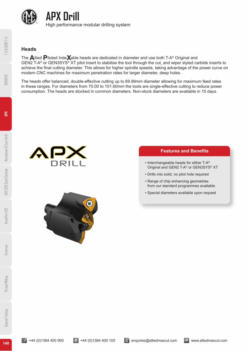
HeadsThe Allied Piloted IndeXable heads are dedicated in diameter and use both T-A® Original and GEN2 T-A® or GEN3SYS® XT pilot insert to stabilise the tool through the cut, and wiper styled carbide inserts to achieve the final cutting diameter. This allows for higher spindle speeds, taking advantage of the power curve on modern CNC machines for maximum penetration rates for larger diameter, deep holes.
The heads offer balanced, double-effective cutting up to 69.99mm diameter allowing for maximum feed rates in these ranges. For diameters from 70.00 to 101.60mm the tools are single-effective cutting to reduce power consumption. The heads are stocked in common diameters. Non-stock diameters are available in 15 days.
• Interchangeable heads for either T-A® Original and GEN2 T-A® or GEN3SYS® XT
• Drills into solid, no pilot hole required
• Range of chip enhancing geometries from our standard programmes available
• Special diameters available upon request
Features and Benefits
T-A
& GE
N2 T-
AGE
N3SY
SAP
XRe
volut
ion &
Cor
e Dril
lAS
C 32
0 So
lid C
arbid
eAc
cuPo
rt 43
2Cr
iterio
nTh
read
Milli
ngSp
ecial
Tooli
ng

+44 (0)1384 400 900 +44 (0)1384 400 105 [email protected] www.alliedmaxcut.com +44 (0)1384 400 900 +44 (0)1384 400 105 [email protected] www.alliedmaxcut.com
APX Drill High performance modular drilling system
149
HoldersThe Allied Piloted IndeXable head uses a fixed series holders with various heads that determine the cutting diameter. There are 10 series to cover the diameter range of 38.00mm to 101.60mm. Non-stocked diameters are available in 15 days.
A unique “X” locator (patent pending) on the head to holder connection allows for simple assembly and superior strength.
Holders are available with a 40mm flanged shank in series 38 & 44 and 50mm flanged shank throughout the range and are designed with through-coolant. They have drill depths up to 704.90mm. Other shank designs are available with 15 days delivery.
For additional information on the APX range please visit www.alliedmaxcut.com or contact our technical department for support and assistance on +44 (0)1384 400 900 or email [email protected]
• 15° slow helix for improved chip evacuation
• Drill depths of up to 3, 5, 8 and 10 x D as standard
• Holders cover up to 7.0mm diameter range
• Special length and diameters available upon request
Features and Benefits
T-A
& GE
N2 T-
AGE
N3SY
SAP
XRe
volut
ion &
Cor
e Dril
lAS
C 32
0 So
lid C
arbid
eAc
cuPo
rt 43
2Cr
iterio
nTh
read
Milli
ngSp
ecial
Tooli
ng

150
Pilot Insert Information
T-A® Original and GEN2 T-A® Insert Geometries
Geometries
Geometries
T-A® original standard geometry offers excellent penetration rates and tool life. Smooth break-out on through holes, drill stability and excellent chip formation characteristics. Suitable for low to high rigidity machining applications. Point angle: 132º • Stocked standard
TC - Tiny Chips• Improved drilling capabilities in long-chipping materials
such as low carbon steels and soft alloys• Effective in lower power machines by allowing better chip
formation at lower feed rates • Unique lip and point designs for excellent chip control• Available in either carbide or HSS substrates• TiN, TiAlN, TiCN and AM200® coatings available• Available in K35 carbide AM200® coated• Stocked standard
GEN2 T-A® standard geometry offers substantial increases in penetration rates and tool life. As well as improved centring, smoother break-out on through holes, increased drill stability, improved chip formation, and lower drill forces. Particularly suited for good to rigid machining applications, primarily used for drilling exotic and high alloy materials, or general use when the M/min surface speed needs to be increasedPoint angle: 132º• Stocked standard
HE - High Elasticity • Excellent chip formation in materials with very high elasticity/
ductility, extremely poor chip forming characteristics.• Effective in lower powered machines• Material example: Low carbon steel
(not suitable for stainless steel)• Available in K35 carbide AM200® coated• Stocked standard
T-A
& GE
N2 T-
AGE
N3SY
SAP
XRe
volut
ion &
Cor
e Dril
lAS
C 32
0 So
lid C
arbid
eAc
cuPo
rt 43
2Cr
iterio
nTh
read
Milli
ngSp
ecial
Tooli
ng
+44 (0)1384 400 900 +44 (0)1384 400 105 [email protected] www.alliedmaxcut.com

151
Pilot Insert Information
GEN3SYS® XT Insert Geometries
Grades
Insert Coatings
Geometries
GEN3SYS® XT Standard geometry is the first choice for steels, alloys and hardened materials offering optimum chip formation in elastic materials, with improved penetration rates. The inserts are available in K35 & K20 grades with AM300® coating providing exceptional wear resistance and up to 20% increase in tool life over AM200®.Point Angle: 140°• Stocked standard
LR - Low Rake • Enhanced LR-XT geometry supports applications
with poor stability and rigidity• First choice for machining structural, cast and forged
steel in materials over 850N/mm² (250BHN)• AM300® coating provides exceptional wear resistance
and up to 20% increase in tool life over AM200®
• Available in K35 & K20• Non stocked standard – delivery 3 weeks
AS - Austenitic Steel• Enhanced AS-XT geometry improves chip control in
Austenitic stainless steel • Stronger point geometry improves penetration rates• First choice for austenitic stainless steels• AM300® coating provides exceptional wear resistance
and up to 20% increase in tool life over AM200®
• Available in K20 • Stocked standard
K35 (C1) CarbideFirst choice in less rigid applications where a tougher grade is required for drilling free machining steel, low/medium carbon steels, alloy steels, high strength steels, tool steels and hardened steels.
P35 (C5) Carbide (IC Inserts)Excellent choice for most applications including drilling free machining steel, low/medium carbon steels, alloy steels, high strength steels, tool steels and hardened steels.
AM300®
• Increased heat resistance over AM200® coating• Provides superior tool life at high penetration rates• Up to 20% increase in tool life over AM200® coating• Colour Light Bronze
AM200®
• First choice for increased heat resistance over TiN, TiCN and TiAlN with improved wear capabilities
• Allows for improved tool life and higher penetration rates• Over 20% increased tool life over TiAlN coating• Colour Copper / Bronze
Note: AM200® Coating available for T-A® Original and GEN2 T-A® inserts only.AM300® coating available for GEN3SYS® XT and IC inserts.
Note: HSS grades also available for T-A® inserts.
K20 (C2) CarbidePrefered choice for drilling titanium alloys, cast aluminium and wrought aluminium together with SG/Nodular cast iron, grey/white iron, aluminium bronze, brass, copper, stainless steels and high temperature alloys.
T-A
& GE
N2 T-
AGE
N3SY
SAP
XRe
volut
ion &
Cor
e Dril
lAS
C 32
0 So
lid C
arbid
eAc
cuPo
rt 43
2Cr
iterio
nTh
read
Milli
ngSp
ecial
Tooli
ng
+44 (0)1384 400 900 +44 (0)1384 400 105 [email protected] www.alliedmaxcut.com
+44 (0)1384 400 900 +44 (0)1384 400 105 [email protected] www.alliedmaxcut.com +44 (0)1384 400 900 +44 (0)1384 400 105 [email protected] www.alliedmaxcut.com
IC Insert Information
152
T-A
& GE
N2 T-
AGE
N3SY
SAP
XRe
volut
ion &
Cor
e Dril
lAS
C 32
0 So
lid C
arbid
eAc
cuPo
rt 43
2Cr
iterio
nTh
read
Milli
ngSp
ecial
Tooli
ng
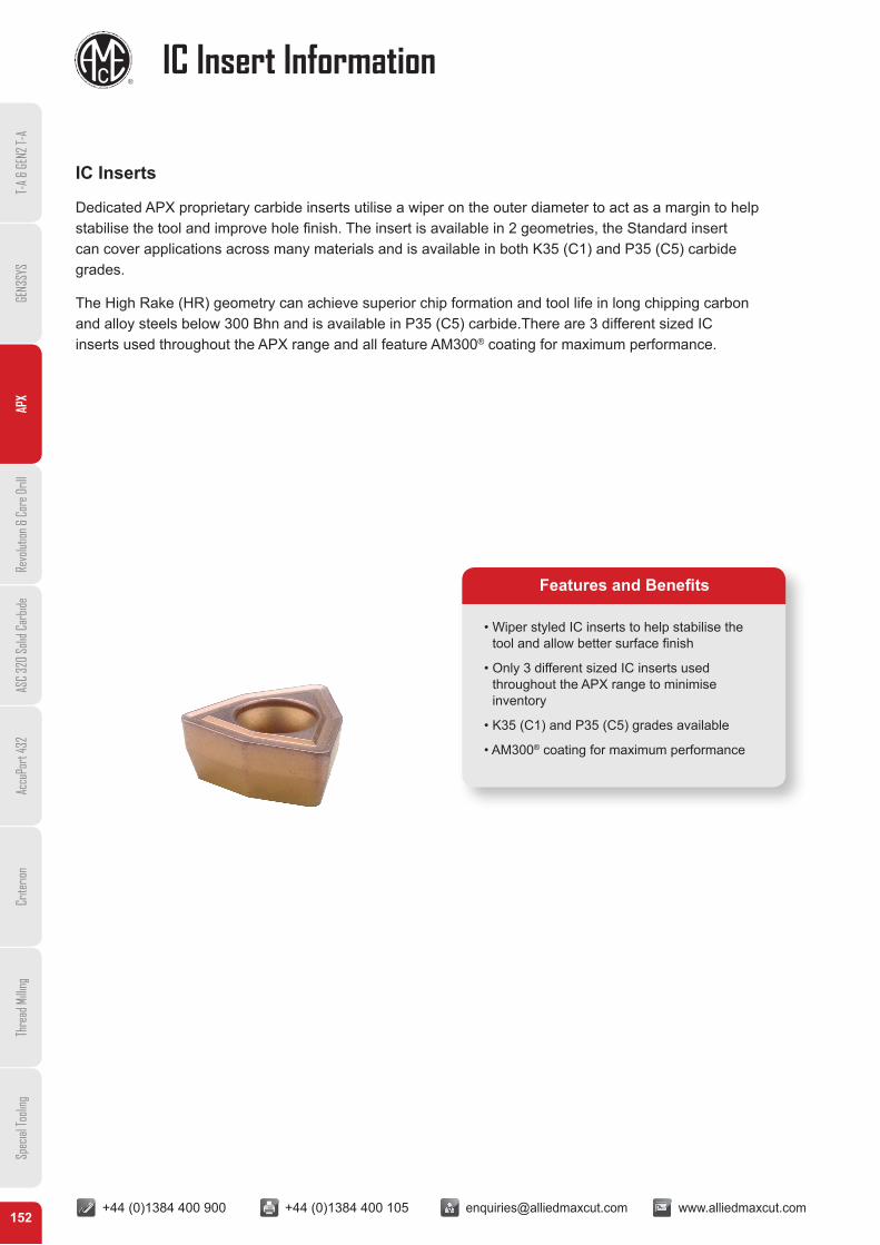
IC Inserts
Dedicated APX proprietary carbide inserts utilise a wiper on the outer diameter to act as a margin to help stabilise the tool and improve hole finish. The insert is available in 2 geometries, the Standard insert can cover applications across many materials and is available in both K35 (C1) and P35 (C5) carbide grades.
The High Rake (HR) geometry can achieve superior chip formation and tool life in long chipping carbon and alloy steels below 300 Bhn and is available in P35 (C5) carbide.There are 3 different sized IC inserts used throughout the APX range and all feature AM300® coating for maximum performance.
• Wiper styled IC inserts to help stabilise the tool and allow better surface finish
• Only 3 different sized IC inserts used throughout the APX range to minimise inventory
• K35 (C1) and P35 (C5) grades available
• AM300® coating for maximum performance
Features and Benefits
+44 (0)1384 400 900 +44 (0)1384 400 105 [email protected] www.alliedmaxcut.com +44 (0)1384 400 900 +44 (0)1384 400 105 [email protected] www.alliedmaxcut.com153
T-A
& GE
N2 T-
AGE
N3SY
SAP
XRe
volut
ion &
Cor
e Dril
lAS
C 32
0 So
lid C
arbid
eAc
cuPo
rt 43
2Cr
iterio
nTh
read
Milli
ngSp
ecial
Tooli
ng
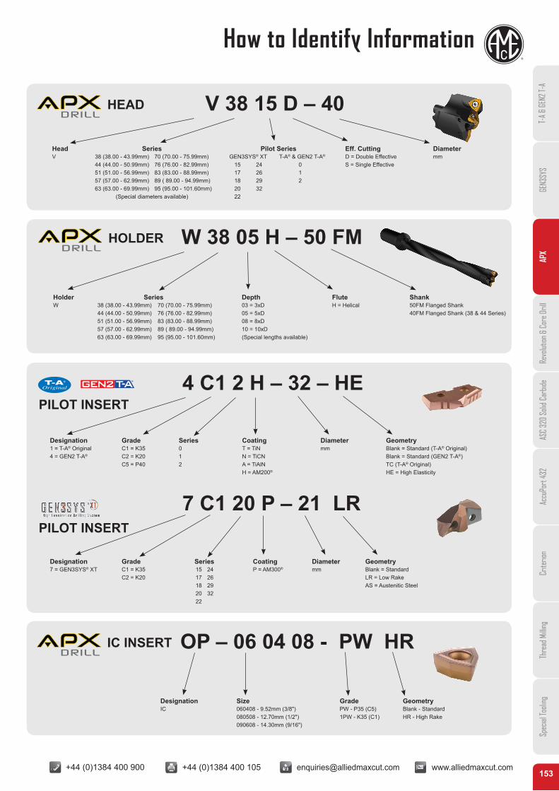
HEAD V 38 15 D – 40
Head Series Pilot Series Eff. Cutting DiameterV 38 (38.00 - 43.99mm) 70 (70.00 - 75.99mm) GEN3SYS® XT T-A® & GEN2 T-A® D = Double Effective mm
44 (44.00 - 50.99mm) 76 (76.00 - 82.99mm) 15 24 0 S = Single Effective51 (51.00 - 56.99mm) 83 (83.00 - 88.99mm) 17 26 157 (57.00 - 62.99mm) 89 ( 89.00 - 94.99mm) 18 29 263 (63.00 - 69.99mm) 95 (95.00 - 101.60mm) 20 32
(Special diameters available) 22
HOLDER W 38 05 H – 50 FM
Holder Series Depth Flute ShankW 38 (38.00 - 43.99mm) 70 (70.00 - 75.99mm) 03 = 3xD H = Helical 50FM Flanged Shank
44 (44.00 - 50.99mm) 76 (76.00 - 82.99mm) 05 = 5xD 40FM Flanged Shank (38 & 44 Series)51 (51.00 - 56.99mm) 83 (83.00 - 88.99mm) 08 = 8xD57 (57.00 - 62.99mm) 89 ( 89.00 - 94.99mm) 10 = 10xD63 (63.00 - 69.99mm) 95 (95.00 - 101.60mm) (Special lengths available)
IC INSERT OP – 06 04 08 - PW HR
Designation Size Grade GeometryIC 060408 - 9.52mm (3/8") PW - P35 (C5) Blank - Standard
080508 - 12.70mm (1/2") 1PW - K35 (C1) HR - High Rake090608 - 14.30mm (9/16")
4 C1 2 H – 32 – HE
7 C1 20 P – 21 LR
Designation Grade Series Coating Diameter Geometry1 = T-A® Original C1 = K35 0 T = TiN mm Blank = Standard (T-A® Original)4 = GEN2 T-A® C2 = K20 1 N = TiCN Blank = Standard (GEN2 T-A®)
C5 = P40 2 A = TiAlN TC (T-A® Original)H = AM200® HE = High Elasticity
Designation Grade Series Coating Diameter Geometry7 = GEN3SYS® XT C1 = K35 15 24 P = AM300® mm Blank = Standard
C2 = K20 17 26 LR = Low Rake18 29 AS = Austenitic Steel20 3222
PILOT INSERT
PILOT INSERT
How to Identify Information
+44 (0)1384 400 900 +44 (0)1384 400 105 [email protected] www.alliedmaxcut.com +44 (0)1384 400 900 +44 (0)1384 400 105 [email protected] www.alliedmaxcut.com
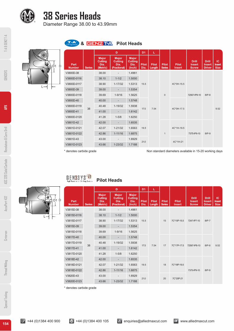
38 Series HeadsDiameter Range 38.00 to 43.99mm
154
Pilot Heads
PartNumber Series
D D1 L
PilotSeries
Pilot Insert
Drill Insert Screw
Drill Insert Driver
IC Insert Size
Major Cutting
Dia. (Metric)
Major Cutting
Dia.(Fractional)
Major Cutting
Dia.(Inch)
Pilot Dia.
Pilot Length
V3815D-38
38
38.00 - 1.4961
15.5
7.54
15 7C*15P-15.5 7247-IP7-10 8IP-7
9.52
V3815D-0116 38.10 1-1/2 1.5000
V3815D-0117 38.90 1-17/32 1.5313
V3815D-39 39.00 - 1.5354
V3815D-0118 39.69 1-9/16 1.5625
V3817D-40 40.00 - 1.5748
17.5 17 7C*17P-17.5 72567-IP8-10 8IP-8V3817D-0119 40.48 1-19/32 1.5938
V3817D-41 41.00 - 1.6142
V3817D-0120 41.28 1-5/8 1.6250
V3818D-42 42.00 - 1.6535
19.5 18 7C*18P-19.5
7375-IP9-10 8IP-9
V3818D-0121 42.07 1-21/32 1.6563
V3818D-0122 42.86 1-11/16 1.6875
V3820D-43 43.00 - 1.692921.0 20 7C*20P-21
V3820D-0123 43.66 1-23/32 1.7188
D1 D
L
* denotes carbide grade Non standard diameters available in 15-20 working days
* denotes carbide grade
& Pilot Heads
PartNumber Series
D D1 L
PilotSeries
Pilot Insert
Drill Insert Screw
Drill Insert Driver
IC Insert Size
Major Cutting
Dia. (Metric)
Major Cutting
Dia.(Fractional)
Major Cutting
Dia.(Inch)
Pilot Dia.
Pilot Length
V3800D-38
38
38.00 - 1.4961
15.5
7.54
0
4C*0H-15.5
72567-IP8-10 8IP-8
9.52
V3800D-0116 38.10 1-1/2 1.5000
V3800D-0117 38.90 1-17/32 1.5313
V3800D-39 39.00 - 1.5354
V3800D-0118 39.69 1-9/16 1.5625
V3800D-40 40.00 - 1.5748
17.5 4C*0H-17.5V3800D-0119 40.48 1-19/32 1.5938
V3800D-41 41.00 - 1.6142
V3800D-0120 41.28 1-5/8 1.6250
V3801D-42 42.00 - 1.6535
19.5
1
4C*1H-19.5
7375-IP9-10 8IP-9
V3801D-0121 42.07 1-21/32 1.6563
V3801D-0122 42.86 1-11/16 1.6875
V3801D-43 43.00 - 1.692921.0 4C*1H-21
V3801D-0123 43.66 1-23/32 1.7188
D1 D
L
T-A
& GE
N2 T-
AGE
N3SY
SAP
XRe
volut
ion &
Cor
e Dril
lAS
C 32
0 So
lid C
arbid
eAc
cuPo
rt 43
2Cr
iterio
nTh
read
Milli
ngSp
ecial
Tooli
ng
+44 (0)1384 400 900 +44 (0)1384 400 105 [email protected] www.alliedmaxcut.com +44 (0)1384 400 900 +44 (0)1384 400 105 [email protected] www.alliedmaxcut.com
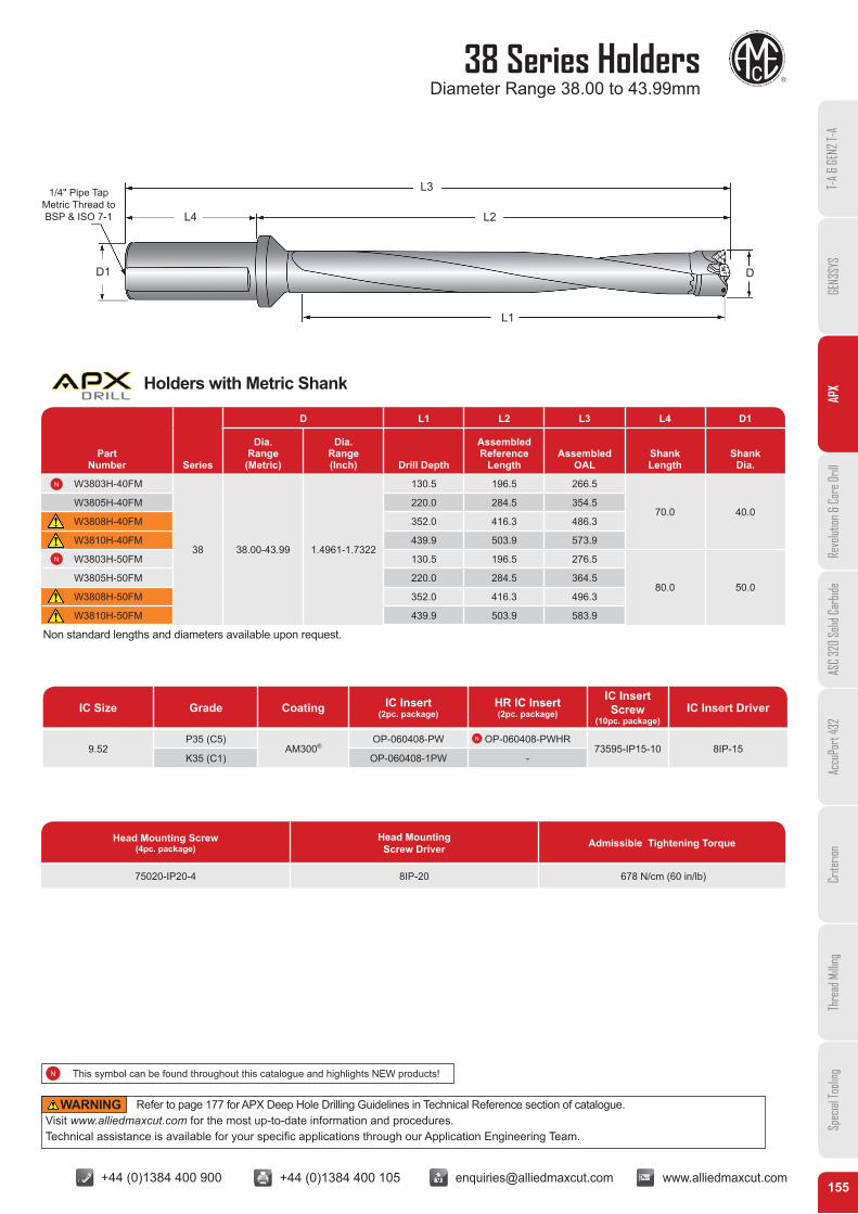
38 Series HoldersDiameter Range 38.00 to 43.99mm
155
IC Size Grade Coating IC Insert (2pc. package)
HR IC Insert(2pc. package)
IC Insert Screw
(10pc. package)IC Insert Driver
9.52P35 (C5)
AM300®OP-060408-PW OP-060408-PWHR
73595-IP15-10 8IP-15K35 (C1) OP-060408-1PW -
Non standard lengths and diameters available upon request.
Part Number Series
D L1 L2 L3 L4 D1
Dia. Range (Metric)
Dia. Range (Inch) Drill Depth
AssembledReference
LengthAssembled
OALShankLength
ShankDia.
W3803H-40FM
38 38.00-43.99 1.4961-1.7322
130.5 196.5 266.5
70.0 40.0W3805H-40FM 220.0 284.5 354.5
W3808H-40FM 352.0 416.3 486.3
W3810H-40FM 439.9 503.9 573.9
W3803H-50FM 130.5 196.5 276.5
80.0 50.0W3805H-50FM 220.0 284.5 364.5
W3808H-50FM 352.0 416.3 496.3
W3810H-50FM 439.9 503.9 583.9
Head Mounting Screw(4pc. package)
Head Mounting Screw Driver Admissible Tightening Torque
75020-IP20-4 8IP-20 678 N/cm (60 in/lb)
D
L1
L2
L3
D1
L4
1/4" Pipe TapMetric Thread to BSP & ISO 7-1
T-A
& GE
N2 T-
AGE
N3SY
SAP
XRe
volut
ion &
Cor
e Dril
lAS
C 32
0 So
lid C
arbid
eAc
cuPo
rt 43
2Cr
iterio
nTh
read
Milli
ngSp
ecial
Tooli
ng
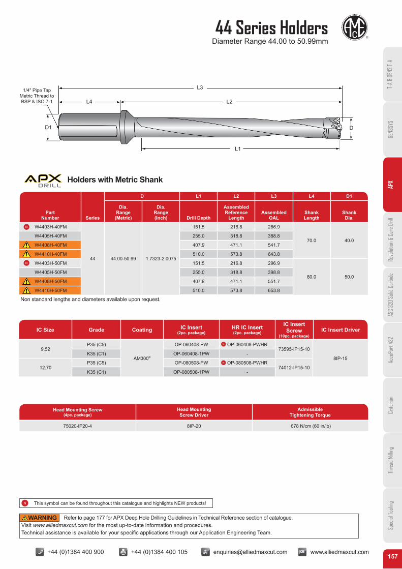
Holders with Metric Shank
Refer to page 177 for APX Deep Hole Drilling Guidelines in Technical Reference section of catalogue. Visit www.alliedmaxcut.com for the most up-to-date information and procedures. Technical assistance is available for your specific applications through our Application Engineering Team.
WARNING
This symbol can be found throughout this catalogue and highlights NEW products!
+44 (0)1384 400 900 +44 (0)1384 400 105 [email protected] www.alliedmaxcut.com +44 (0)1384 400 900 +44 (0)1384 400 105 [email protected] www.alliedmaxcut.com
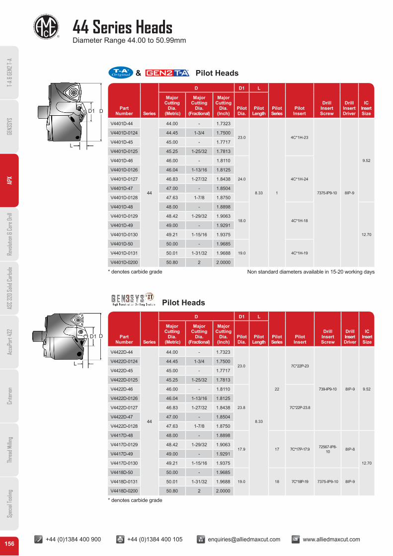
44 Series HeadsDiameter Range 44.00 to 50.99mm
156
PartNumber Series
D D1 L
PilotSeries
Pilot Insert
Drill Insert Screw
Drill Insert Driver
IC Insert Size
Major Cutting
Dia. (Metric)
Major Cutting
Dia.(Fractional)
Major Cutting
Dia.(Inch)
Pilot Dia.
Pilot Length
PartNumber Series
D D1 L
PilotSeries
Pilot Insert
Drill Insert Screw
Drill Insert Driver
IC Insert Size
Major Cutting
Dia. (Metric)
Major Cutting
Dia.(Fractional)
Major Cutting
Dia.(Inch)
Pilot Dia.
Pilot Length
V4401D-44
44
44.00 - 1.7323
23.0
8.33 1
4C*1H-23
7375-IP9-10 8IP-9
9.52
V4401D-0124 44.45 1-3/4 1.7500
V4401D-45 45.00 - 1.7717
V4401D-0125 45.25 1-25/32 1.7813
V4401D-46 46.00 - 1.8110
24.0 4C*1H-24
V4401D-0126 46.04 1-13/16 1.8125
V4401D-0127 46.83 1-27/32 1.8438
V4401D-47 47.00 - 1.8504
V4401D-0128 47.63 1-7/8 1.8750
V4401D-48 48.00 - 1.8898
18.0 4C*1H-18
12.70
V4401D-0129 48.42 1-29/32 1.9063
V4401D-49 49.00 - 1.9291
V4401D-0130 49.21 1-15/16 1.9375
V4401D-50 50.00 - 1.9685
19.0 4C*1H-19V4401D-0131 50.01 1-31/32 1.9688
V4401D-0200 50.80 2 2.0000
V4422D-44
44
44.00 - 1.7323
23.0
8.33
22
7C*22P-23
739-IP9-10 8IP-9 9.52
V4422D-0124 44.45 1-3/4 1.7500
V4422D-45 45.00 - 1.7717
V4422D-0125 45.25 1-25/32 1.7813
V4422D-46 46.00 - 1.8110
23.8 7C*22P-23.8
V4422D-0126 46.04 1-13/16 1.8125
V4422D-0127 46.83 1-27/32 1.8438
V4422D-47 47.00 - 1.8504
V4422D-0128 47.63 1-7/8 1.8750
V4417D-48 48.00 - 1.8898
17.9 17 7C*17P-17.9 72567-IP8-10 8IP-8
12.70
V4417D-0129 48.42 1-29/32 1.9063
V4417D-49 49.00 - 1.9291
V4417D-0130 49.21 1-15/16 1.9375
V4418D-50 50.00 - 1.9685
19.0 18 7C*18P-19 7375-IP9-10 8IP-9V4418D-0131 50.01 1-31/32 1.9688
V4418D-0200 50.80 2 2.0000
* denotes carbide grade
* denotes carbide grade
Non standard diameters available in 15-20 working days
D1 D
L
D1 D
L
T-A
& GE
N2 T-
AGE
N3SY
SAP
XRe
volut
ion &
Cor
e Dril
lAS
C 32
0 So
lid C
arbid
eAc
cuPo
rt 43
2Cr
iterio
nTh
read
Milli
ngSp
ecial
Tooli
ng
Pilot Heads
& Pilot Heads
+44 (0)1384 400 900 +44 (0)1384 400 105 [email protected] www.alliedmaxcut.com +44 (0)1384 400 900 +44 (0)1384 400 105 [email protected] www.alliedmaxcut.com
Part Number Series
D L1 L2 L3 L4 D1
Dia. Range (Metric)
Dia. Range (Inch) Drill Depth
AssembledReference
LengthAssembled
OALShankLength
ShankDia.
W4403H-40FM
44 44.00-50.99 1.7323-2.0075
151.5 216.8 286.9
70.0 40.0W4405H-40FM 255.0 318.8 388.8
W4408H-40FM 407.9 471.1 541.7
W4410H-40FM 510.0 573.8 643.8
W4403H-50FM 151.5 216.8 296.9
80.0 50.0W4405H-50FM 255.0 318.8 398.8
W4408H-50FM 407.9 471.1 551.7
W4410H-50FM 510.0 573.8 653.8
44 Series HoldersDiameter Range 44.00 to 50.99mm
157
IC Size Grade Coating IC Insert (2pc. package)
HR IC Insert (2pc. package)
IC Insert Screw
(10pc. package)IC Insert Driver
9.52P35 (C5)
AM300®
OP-060408-PW OP-060408-PWHR73595-IP15-10
8IP-15K35 (C1) OP-060408-1PW -
12.70P35 (C5) OP-080508-PW OP-080508-PWHR
74012-IP15-10K35 (C1) OP-080508-1PW -
Head Mounting Screw(4pc. package)
Head Mounting Screw Driver
Admissible Tightening Torque
75020-IP20-4 8IP-20 678 N/cm (60 in/lb)
Non standard lengths and diameters available upon request.
D
L1
L2
L3
D1
L4
1/4" Pipe TapMetric Thread to BSP & ISO 7-1
T-A
& GE
N2 T-
AGE
N3SY
SAP
XRe
volut
ion &
Cor
e Dril
lAS
C 32
0 So
lid C
arbid
eAc
cuPo
rt 43
2Cr
iterio
nTh
read
Milli
ngSp
ecial
Tooli
ng
Holders with Metric Shank
Refer to page 177 for APX Deep Hole Drilling Guidelines in Technical Reference section of catalogue. Visit www.alliedmaxcut.com for the most up-to-date information and procedures. Technical assistance is available for your specific applications through our Application Engineering Team.
WARNING
This symbol can be found throughout this catalogue and highlights NEW products!

+44 (0)1384 400 900 +44 (0)1384 400 105 [email protected] www.alliedmaxcut.com +44 (0)1384 400 900 +44 (0)1384 400 105 [email protected] www.alliedmaxcut.com
51 Series HeadsDiameter Range 51.00 to 56.99mm
158
PartNumber Series
D D1 L
PilotSeries
Pilot Insert
Drill Insert Screw
Drill Insert Driver
IC Insert Size
Major Cutting
Dia. (Metric)
Major Cutting
Dia.(Fractional)
Major Cutting
Dia.(Inch)
Pilot Dia.
Pilot Length
PartNumber Series
D D1 L
PilotSeries
Pilot Insert
Drill Insert Screw
Drill Insert Driver
IC Insert Size
Major Cutting
Dia. (Metric)
Major Cutting
Dia.(Fractional)
Major Cutting
Dia.(Inch)
Pilot Dia.
Pilot Length
V5101D-51
51
51.00 - 2.0079
20.0
8.73 1
4C*1H-20
7375-IP9-10 8IP-912.70
V5101D-0201 51.59 2-1/32 2.0313
V5101D-52 52.00 - 2.0472
V5101D-0202 52.39 2-1/16 2.0625
V5101D-53 53.00 - 2.0866
21.5 4C*1H-21.5V5101D-0203 53.18 2-3/32 2.0938
V5101D-0204 53.98 2-1/8 2.1250
V5101D-54 54.00 - 2.1260
24.0 4C*1H-24
V5101D-0205 54.77 2-5/32 2.1563
V5101D-55 55.00 - 2.1654
V5101D-0206 55.56 2-3/16 2.1875
V5101D-56 56.00 - 2.2047
V5101D-0207 56.36 2-7/32 2.2188 21.0 4C*1H-21 14.30
V5118D-51
51
51.00 - 2.0079
19.8
8.73
18 7C*18P-19.8
7375-IP9-10
8IP-912.70
V5118D-0201 51.59 2-1/32 2.0313
V5118D-52 52.00 - 2.0472
V5118D-0202 52.39 2-1/16 2.0625
V5120D-53 53.00 - 2.0866
21.5 20 7C*20P-21.5V5120D-0203 53.18 2-3/32 2.0938
V5120D-0204 53.98 2-1/8 2.1250
V5122D-54 54.00 - 2.1260
23.8 22 7C*22P-23.8 739-IP9-10
V5122D-0205 54.77 2-5/32 2.1563
V5122D-55 55.00 - 2.1654
V5122D-0206 55.56 2-3/16 2.1875
V5122D-56 56.00 - 2.2047
V5120D-0207 56.36 2-7/32 2.2188 21.0 20 7C*20P-21 7375-IP9-10 14.30
* denotes carbide grade
* denotes carbide grade
Non standard diameters available in 15-20 working days
D1 D
L
D1 D
L
T-A
& GE
N2 T-
AGE
N3SY
SAP
XRe
volut
ion &
Cor
e Dril
lAS
C 32
0 So
lid C
arbid
eAc
cuPo
rt 43
2Cr
iterio
nTh
read
Milli
ngSp
ecial
Tooli
ng
Pilot Heads
& Pilot Heads

+44 (0)1384 400 900 +44 (0)1384 400 105 [email protected] www.alliedmaxcut.com +44 (0)1384 400 900 +44 (0)1384 400 105 [email protected] www.alliedmaxcut.com
51 Series HoldersDiameter Range 51.00 to 56.99mm
159
IC Size Grade Coating IC Insert (2pc. package)
HR IC Insert (2pc. package)
IC Insert Screw
(10pc. package)IC Insert Driver
12.70P35 (C5)
AM300®
OP-080508-PW OP-080508-PWHR74012-IP15-10 8IP-15
K35 (C1) OP-080508-1PW -
14.30P35 (C5) OP-090608-PW OP-090608-PWHR
75014-IP20-10 8IP-20K35 (C1) OP-090608-1PW -
Part Number Series
D L1 L2 L3 L4 D1
Dia. Range (Metric)
Dia. Range (Inch) Drill Depth
AssembledReference
LengthAssembled
OALShankLength
ShankDia.
W5103H-50FM
51 51.00-56.99 2.0076-2.2438
161.8 225.5 305.5
80.0 50.0W5105H-50FM 285.0 339.6 419.6
W5108H-50FM 455.9 510.5 590.5
W5110H-50FM 570.0 624.6 704.6
Head Mounting Screw(4pc. package)
Head Mounting Screw Driver
Admissible Tightening Torque
75020-IP20-4 8IP-20 678 N/cm (60 in/lb)
Non standard lengths and diameters available upon request.
D
L1
L2
L3
D1
L4
1/4" Pipe TapMetric Thread to BSP & ISO 7-1
T-A
& GE
N2 T-
AGE
N3SY
SAP
XRe
volut
ion &
Cor
e Dril
lAS
C 32
0 So
lid C
arbid
eAc
cuPo
rt 43
2Cr
iterio
nTh
read
Milli
ngSp
ecial
Tooli
ng
Holders with Metric Shank
Refer to page 177 for APX Deep Hole Drilling Guidelines in Technical Reference section of catalogue. Visit www.alliedmaxcut.com for the most up-to-date information and procedures. Technical assistance is available for your specific applications through our Application Engineering Team.
WARNING
This symbol can be found throughout this catalogue and highlights NEW products!

+44 (0)1384 400 900 +44 (0)1384 400 105 [email protected] www.alliedmaxcut.com +44 (0)1384 400 900 +44 (0)1384 400 105 [email protected] www.alliedmaxcut.com
57 Series HeadsDiameter Range 57.00 to 62.99mm
160
PartNumber Series
D D1 L
PilotSeries
Pilot Insert
Drill Insert Screw
Drill Insert Driver
IC Insert Size
Major Cutting
Dia. (Metric)
Major Cutting
Dia.(Fractional)
Major Cutting
Dia.(Inch)
Pilot Dia.
Pilot Length
PartNumber Series
D D1 L
PilotSeries
Pilot Insert
Drill Insert Screw
Drill Insert Driver
IC Insert Size
Major Cutting
Dia. (Metric)
Major Cutting
Dia.(Fractional)
Major Cutting
Dia.(Inch)
Pilot Dia.
Pilot Length
V5701D-57
57
57.00 - 2.2441
23.0
9.92
1
4C*1H-23
739-IP9-10 8IP-9
14.30
V5701D-0208 57.15 2-1/4 2.2500
V5701D-0209 57.94 2-9/32 2.2813
V5701D-58 58.00 - 2.2835
V5701D-0210 58.74 2-5/16 2.3125
V5701D-59 59.00 - 2.3228
24.0 4C*1H-24V5701D-0211 59.53 2-11/32 2.3438
V5701D-60 60.00 - 2.3622
V5701D-0212 60.33 2-3/8 2.3750
V5702D-61 61.00 - 2.4016
25.5
2
4C*2H-25.5
7495-IP15-10 8IP-15
V5702D-0213 61.12 2-13/32 2.4063
V5702D-0214 61.91 2-7/16 2.4375
V5702D-62 62.00 - 2.440927.0 4C*2H-27
V5702D-0215 62.71 2-15/32 2.4688
V5722D-57
57
57.00 - 2.2441
23.0
9.92
22
7C*22P-23
739-IP9-10 8IP-9
14.30
V5722D-0208 57.15 2-1/4 2.2500
V5722D-0209 57.94 2-9/32 2.2813
V5722D-58 58.00 - 2.2835
V5722D-0210 58.74 2-5/16 2.3125
V5722D-59 59.00 - 2.3228
23.8 7C*22P-23.8 V5722D-0211 59.53 2-11/32 2.3438
V5722D-60 60.00 - 2.3622
V5722D-0212 60.33 2-3/8 2.3750
V5724D-61 61.00 - 2.4016
25.5 24 7C*24P-25.5V5724D-0213 61.12 2-13/32 2.4063
V5724D-0214 61.91 2-7/16 2.4375
V5726D-62 62.00 - 2.440927.0 26 7C*26P-27 7495-IP15-10 8IP-15
V5726D-0215 62.71 2-15/32 2.4688
* denotes carbide grade
* denotes carbide grade
Non standard diameters available in 15-20 working days
D1 D
L
D1 D
L
T-A
& GE
N2 T-
AGE
N3SY
SAP
XRe
volut
ion &
Cor
e Dril
lAS
C 32
0 So
lid C
arbid
eAc
cuPo
rt 43
2Cr
iterio
nTh
read
Milli
ngSp
ecial
Tooli
ng
Pilot Heads
& Pilot Heads

+44 (0)1384 400 900 +44 (0)1384 400 105 [email protected] www.alliedmaxcut.com +44 (0)1384 400 900 +44 (0)1384 400 105 [email protected] www.alliedmaxcut.com
57 Series HoldersDiameter Range 57.00 to 62.99mm
161
IC Size Grade Coating IC Insert (2pc. package)
HR IC Insert(2pc. package)
IC Insert Screw
(10pc. package)IC Insert Driver
14.30P35 (C5)
AM300®OP-090608-PW OP-090608-PWHR
75014-IP20-10 8IP-20K35 (C1) OP-090608-1PW -
Part Number Series
D L1 L2 L3 L4 D1
Dia. Range (Metric)
Dia. Range (Inch) Drill Depth
AssembledReference
LengthAssembled
OALShankLength
ShankDia.
W5703H-50FM
57 57.00-62.99 2.2439-2.4799
179.9 242.7 322.7
80.0 50.0W5705H-50FM 315.0 368.6 448.6
W5708H-50FM 503.9 557.8 637.8
W5710H-50FM 626.9 683.8 763.8
Head Mounting Screw(4pc. package)
Head Mounting Screw Driver
Admissible Tightening Torque
75020-IP20-4 8IP-20 678 N/cm (60 in/lb)
Non standard lengths and diameters available upon request.
D
L1
L2
L3
D1
L4
1/4" Pipe TapMetric Thread to BSP & ISO 7-1
T-A
& GE
N2 T-
AGE
N3SY
SAP
XRe
volut
ion &
Cor
e Dril
lAS
C 32
0 So
lid C
arbid
eAc
cuPo
rt 43
2Cr
iterio
nTh
read
Milli
ngSp
ecial
Tooli
ng
Holders with Metric Shank
Refer to page 177 for APX Deep Hole Drilling Guidelines in Technical Reference section of catalogue. Visit www.alliedmaxcut.com for the most up-to-date information and procedures. Technical assistance is available for your specific applications through our Application Engineering Team.
WARNING
This symbol can be found throughout this catalogue and highlights NEW products!
+44 (0)1384 400 900 +44 (0)1384 400 105 [email protected] www.alliedmaxcut.com +44 (0)1384 400 900 +44 (0)1384 400 105 [email protected] www.alliedmaxcut.com
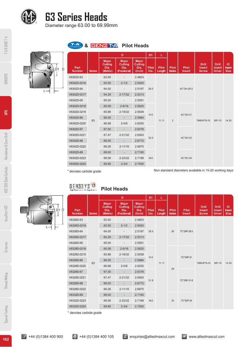
63 Series HeadsDiameter range 63.00 to 69.99mm
162
PartNumber Series
D D1 L
PilotSeries
Pilot Insert
Drill Insert Screw
Drill Insert Driver
IC Insert Size
Major Cutting
Dia. (Metric)
Major Cutting
Dia.(Fractional)
Major Cutting
Dia.(Inch)
Pilot Dia.
Pilot Length
Part Number Series
D D1 L
PilotSeries
Pilot Insert
Drill Insert Screw
Drill Insert Driver
IC Insert Size
Major Cutting
Dia. (Metric)
Major Cutting
Dia.(Fractional)
Major Cutting
Dia.(Inch)
Pilot Dia.
Pilot Length
V6302D-63
63
63.00 - 2.4803
28.5
11.11 2
4C*2H-28.5
7495-IP15-10 8IP-15 14.30
V6302D-0216 63.50 2-1/2 2.5000
V6302D-64 64.00 - 2.5197
V6302D-0217 64.29 2-17/32 2.5313
V6302D-65 65.00 - 2.5591
V6302D-0218 65.09 2-9/16 2.5625
31.0 4C*2H-31V6302D-0219 65.88 2-19/32 2.5938
V6302D-66 66.00 - 2.5984
V6302D-0220 66.68 2-5/8 2.6250
V6302D-67 67.00 - 2.6378
32.0 4C*2H-32V6302D-0221 67.47 2-21/32 2.6563
V6302D-68 68.00 - 2.6772
V6302D-0222 68.26 2-11/16 2.6875
V6302D-69 69.00 - 2.7165
34.0 4C*2H-34V6302D-0223 69.06 2-23/32 2.7188
V6302D-0224 69.85 2-3/4 2.7500
V6326D-63
63
63.00 - 2.4803
28.5
11.11
26 7C*26P-28.5
7495-IP15-10 8IP-15 14.30
V6326D-0216 63.50 2-1/2 2.5000
V6326D-64 64.00 - 2.5197
V6326D-0217 64.29 2-17/32 2.5313
V6326D-65 65.00 - 2.5591
V6329D-0218 65.09 2-9/16 2.5625
31.0
29
7C*29P-31V6329D-0219 65.88 2-19/32 2.5938
V6329D-66 66.00 - 2.5984
V6329D-0220 66.68 2-5/8 2.6250
V6329D-67 67.00 - 2.6378
31.8 7C*29P-31.8V6329D-0221 67.47 2-21/32 2.6563
V6329D-68 68.00 - 2.6772
V6329D-0222 68.26 2-11/16 2.6875
V6332D-69 69.00 - 2.7165
34.0 32 7C*32P-34V6332D-0223 69.06 2-23/32 2.7188
V6332D-0224 69.85 2-3/4 2.7500
* denotes carbide grade
* denotes carbide grade
Non standard diameters available in 15-20 working days
D1 D
L
D1 D
L
T-A
& GE
N2 T-
AGE
N3SY
SAP
XRe
volut
ion &
Cor
e Dril
lAS
C 32
0 So
lid C
arbid
eAc
cuPo
rt 43
2Cr
iterio
nTh
read
Milli
ngSp
ecial
Tooli
ng
Pilot Heads
& Pilot Heads

+44 (0)1384 400 900 +44 (0)1384 400 105 [email protected] www.alliedmaxcut.com +44 (0)1384 400 900 +44 (0)1384 400 105 [email protected] www.alliedmaxcut.com
63 Series HoldersDiameter range 63.00 to 69.99mm
163
IC Size Grade Coating IC Insert (2pc. package)
HR IC Insert (2pc. package)
IC Insert Screw
(10 pc. package)IC Insert Driver
14.30P35 (C5)
AM300®OP-090608-PW OP-090608-PWHR
75014-IP20-10 8IP-20K35 (C1) OP-090608-1PW -
Part Number Series
D L1 L2 L3 L4 D1
Dia. Range (Metric)
Dia. Range (Inch) Drill Depth
AssembledReference
LengthAssembled
OALShankLength
ShankDia.
W6303H-50FM
63 63.00-69.99 2.4800-2.7555
200.8 262.6 342.6
80.0 50.0W6305H-50FM 350.0 402.6 482.6
W6308H-50FM 560.0 612.6 692.6
W6310H-50FM 688.3 740.9 820.9
Head Mounting Screw(4pc. package)
Head Mounting Screw Driver
Admissible Tightening Torque
75020-IP20-4 8IP-20 678 N/cm (60 in/lb)
Non standard lengths and diameters available upon request.
D
L1
L2
L3
D1
L4
1/4" Pipe TapMetric Thread to BSP & ISO 7-1
T-A
& GE
N2 T-
AGE
N3SY
SAP
XRe
volut
ion &
Cor
e Dril
lAS
C 32
0 So
lid C
arbid
eAc
cuPo
rt 43
2Cr
iterio
nTh
read
Milli
ngSp
ecial
Tooli
ng
Holders with Metric Shank
Refer to page 177 for APX Deep Hole Drilling Guidelines in Technical Reference section of catalogue. Visit www.alliedmaxcut.com for the most up-to-date information and procedures. Technical assistance is available for your specific applications through our Application Engineering Team.
WARNING
This symbol can be found throughout this catalogue and highlights NEW products!
+44 (0)1384 400 900 +44 (0)1384 400 105 [email protected] www.alliedmaxcut.com +44 (0)1384 400 900 +44 (0)1384 400 105 [email protected] www.alliedmaxcut.com
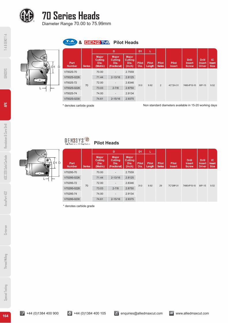
70 Series HeadsDiameter Range 70.00 to 75.99mm
164
Part Number Series
D D1 L
PilotSeries
Pilot Insert
Drill Insert Screw
Drill Insert Driver
IC Insert Size
Major Cutting
Dia. (Metric)
Major Cutting
Dia.(Fractional)
Major Cutting
Dia.(Inch)
Pilot Dia.
Pilot Length
Part Number Series
D D1 L
PilotSeries
Pilot Insert
Drill Insert Screw
Drill Insert Driver
IC Insert Size
Major Cutting
Dia. (Metric)
Major Cutting
Dia.(Fractional)
Major Cutting
Dia.(Inch)
Pilot Dia.
Pilot Length
V7002S-70
70
70.00 - 2.7559
31.0 9.92 2 4C*2H-31 7495-IP15-10 8IP-15 9.52
V7002S-0226 71.44 2-13/16 2.8125
V7002S-72 72.00 - 2.8346
V7002S-0228 73.03 2-7/8 2.8750
V7002S-74 74.00 - 2.9134
V7002S-0230 74.61 2-15/16 2.9375
V7029S-70
70
70.00 - 2.7559
31.0 9.92 29 7C*29P-31 7495-IP15-10 8IP-15 9.52
V7029S-0226 71.44 2-13/16 2.8125
V7029S-72 72.00 - 2.8346
V7029S-0228 73.03 2-7/8 2.8750
V7029S-74 74.00 - 2.9134
V7029S-0230 74.61 2-15/16 2.9375
* denotes carbide grade
* denotes carbide grade
D1 D
L
D1 D
L
Non standard diameters available in 15-20 working days
T-A
& GE
N2 T-
AGE
N3SY
SAP
XRe
volut
ion &
Cor
e Dril
lAS
C 32
0 So
lid C
arbid
eAc
cuPo
rt 43
2Cr
iterio
nTh
read
Milli
ngSp
ecial
Tooli
ng
Pilot Heads
& Pilot Heads
+44 (0)1384 400 900 +44 (0)1384 400 105 [email protected] www.alliedmaxcut.com +44 (0)1384 400 900 +44 (0)1384 400 105 [email protected] www.alliedmaxcut.com
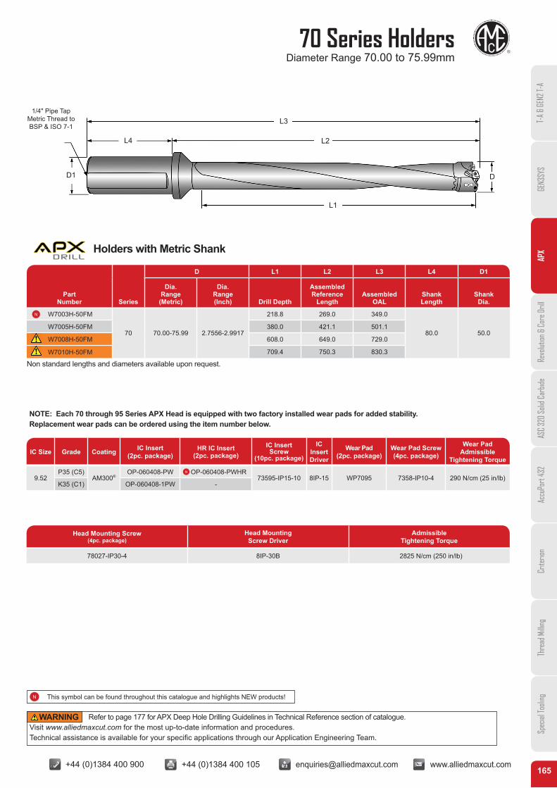
70 Series HoldersDiameter Range 70.00 to 75.99mm
165
Part Number Series
D L1 L2 L3 L4 D1
Dia. Range (Metric)
Dia. Range (Inch) Drill Depth
AssembledReference
LengthAssembled
OALShankLength
ShankDia.
W7003H-50FM
70 70.00-75.99 2.7556-2.9917
218.8 269.0 349.0
80.0 50.0W7005H-50FM 380.0 421.1 501.1
W7008H-50FM 608.0 649.0 729.0
W7010H-50FM 709.4 750.3 830.3
Head Mounting Screw(4pc. package)
Head Mounting Screw Driver
Admissible Tightening Torque
78027-IP30-4 8IP-30B 2825 N/cm (250 in/lb)
IC Size Grade Coating IC Insert (2pc. package)
HR IC Insert (2pc. package)
IC Insert Screw
(10pc. package)
IC Insert Driver
Wear Pad (2pc. package)
Wear Pad Screw (4pc. package)
Wear Pad Admissible
Tightening Torque
9.52P35 (C5)
AM300®OP-060408-PW OP-060408-PWHR
73595-IP15-10 8IP-15 WP7095 7358-IP10-4 290 N/cm (25 in/lb)K35 (C1) OP-060408-1PW -
NOTE: Each 70 through 95 Series APX Head is equipped with two factory installed wear pads for added stability. Replacement wear pads can be ordered using the item number below.
D
L1
L2
L3
D1
L4
1/4" Pipe TapMetric Thread to BSP & ISO 7-1
Non standard lengths and diameters available upon request.
T-A
& GE
N2 T-
AGE
N3SY
SAP
XRe
volut
ion &
Cor
e Dril
lAS
C 32
0 So
lid C
arbid
eAc
cuPo
rt 43
2Cr
iterio
nTh
read
Milli
ngSp
ecial
Tooli
ng
Holders with Metric Shank
Refer to page 177 for APX Deep Hole Drilling Guidelines in Technical Reference section of catalogue. Visit www.alliedmaxcut.com for the most up-to-date information and procedures. Technical assistance is available for your specific applications through our Application Engineering Team.
WARNING
This symbol can be found throughout this catalogue and highlights NEW products!

+44 (0)1384 400 900 +44 (0)1384 400 105 [email protected] www.alliedmaxcut.com +44 (0)1384 400 900 +44 (0)1384 400 105 [email protected] www.alliedmaxcut.com
76 Series HeadsDiameter Range 76.00 to 82.99mm
166
Part Number Series
D D1 L
PilotSeries
Pilot Insert
Drill Insert Screw
Drill Insert Driver
IC Insert Size
Major Cutting
Dia. (Metric)
Major Cutting
Dia.(Fractional)
Major Cutting
Dia.(Inch)
Pilot Dia.
Pilot Length
Part Number Series
D D1 L
PilotSeries
Pilot Insert
Drill Insert Screw
Drill Insert Driver
IC Insert Size
Major Cutting
Dia. (Metric)
Major Cutting
Dia.(Fractional)
Major Cutting
Dia.(Inch)
Pilot Dia.
Pilot Length
V7602S-76
76
76.00 - 2.9921
31.0 10.32 2 4C*2H-31 7495-IP15-10 8IP-15 12.70
V7602S-0300 76.20 3 3.0000
V7602S-0302 77.79 3-1/16 3.0625
V7602S-78 78.00 - 3.0709
V7602S-0304 79.38 3-1/8 3.1250
V7602S-80 80.00 - 3.1496
V7602S-0306 80.96 3-3/16 3.1875
V7602S-82 82.00 - 3.2282
V7602S-0308 82.55 3-1/4 3.2500
V7629S-76
76
76.00 - 2.9921
31.0 10.32 29 7C*29P-31 7495-IP15-10 8IP-15 12.70
V7629S-0300 76.20 3 3.0000
V7629S-0302 77.79 3-1/16 3.0625
V7629S-78 78.00 - 3.0709
V7629S-0304 79.38 3-1/8 3.1250
V7629S-80 80.00 - 3.1496
V7629S-0306 80.96 3-3/16 3.1875
V7629S-82 82.00 - 3.2283
V7629S-0308 82.55 3-1/4 3.2500
* denotes carbide grade
* denotes carbide grade
Non standard diameters available in 15-20 working days
D1 D
L
D1 D
L
T-A
& GE
N2 T-
AGE
N3SY
SAP
XRe
volut
ion &
Cor
e Dril
lAS
C 32
0 So
lid C
arbid
eAc
cuPo
rt 43
2Cr
iterio
nTh
read
Milli
ngSp
ecial
Tooli
ng
Pilot Heads
& Pilot Heads
+44 (0)1384 400 900 +44 (0)1384 400 105 [email protected] www.alliedmaxcut.com +44 (0)1384 400 900 +44 (0)1384 400 105 [email protected] www.alliedmaxcut.com
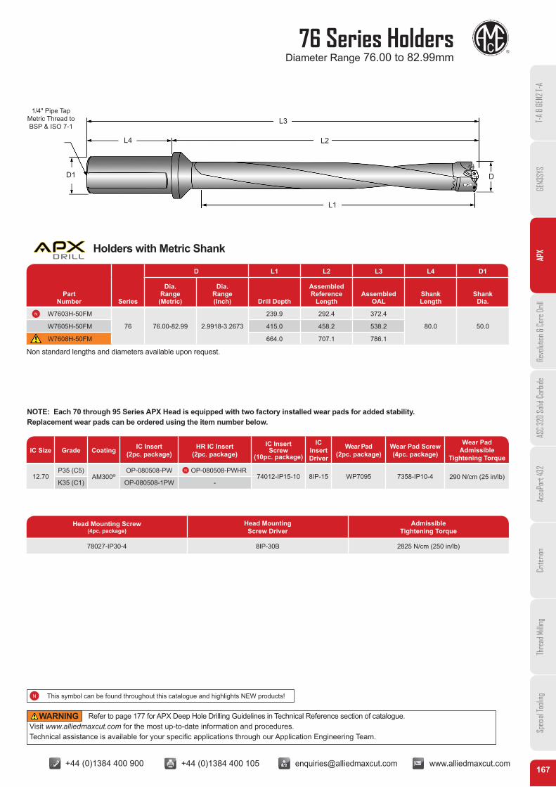
76 Series Holders Diameter Range 76.00 to 82.99mm
167
IC Size Grade Coating IC Insert (2pc. package)
HR IC Insert (2pc. package)
IC Insert Screw
(10pc. package)
IC Insert Driver
Wear Pad (2pc. package)
Wear Pad Screw (4pc. package)
Wear Pad Admissible
Tightening Torque
12.70P35 (C5)
AM300®OP-080508-PW OP-080508-PWHR
74012-IP15-10 8IP-15 WP7095 7358-IP10-4 290 N/cm (25 in/lb)K35 (C1) OP-080508-1PW -
NOTE: Each 70 through 95 Series APX Head is equipped with two factory installed wear pads for added stability. Replacement wear pads can be ordered using the item number below.
Part Number Series
D L1 L2 L3 L4 D1
Dia. Range (Metric)
Dia. Range (Inch) Drill Depth
AssembledReference
LengthAssembled
OALShankLength
ShankDia.
W7603H-50FM
76 76.00-82.99 2.9918-3.2673
239.9 292.4 372.4
80.0 50.0W7605H-50FM 415.0 458.2 538.2
W7608H-50FM 664.0 707.1 786.1
Head Mounting Screw(4pc. package)
Head Mounting Screw Driver
Admissible Tightening Torque
78027-IP30-4 8IP-30B 2825 N/cm (250 in/lb)
Non standard lengths and diameters available upon request.
D
L1
L2
L3
D1
L4
1/4" Pipe TapMetric Thread to BSP & ISO 7-1
T-A
& GE
N2 T-
AGE
N3SY
SAP
XRe
volut
ion &
Cor
e Dril
lAS
C 32
0 So
lid C
arbid
eAc
cuPo
rt 43
2Cr
iterio
nTh
read
Milli
ngSp
ecial
Tooli
ng
Holders with Metric Shank
Refer to page 177 for APX Deep Hole Drilling Guidelines in Technical Reference section of catalogue. Visit www.alliedmaxcut.com for the most up-to-date information and procedures. Technical assistance is available for your specific applications through our Application Engineering Team.
WARNING
This symbol can be found throughout this catalogue and highlights NEW products!

+44 (0)1384 400 900 +44 (0)1384 400 105 [email protected] www.alliedmaxcut.com +44 (0)1384 400 900 +44 (0)1384 400 105 [email protected] www.alliedmaxcut.com
83 Series HeadsDiameter Range 83.00 to 88.99mm
168
Part Number Series
D D1 L
PilotSeries
Pilot Insert
Drill Insert Screw
Drill Insert Driver
IC Insert Size
Major Cutting
Dia. (Metric)
Major Cutting
Dia.(Fractional)
Major Cutting
Dia.(Inch)
Pilot Dia.
Pilot Length
Part Number Series
D D1 L
PilotSeries
Pilot Insert
Drill Insert Screw
Drill Insert Driver
IC Insert Size
Major Cutting
Dia. (Metric)
Major Cutting
Dia.(Fractional)
Major Cutting
Dia.(Inch)
Pilot Dia.
Pilot Length
V8302S-84
83
84.00 - 3.3071
35.0 11.11 2 4C*2H-35 7495-IP15-10 8IP-15 12.70
V8302S-0310 84.14 3-5/16 3.3125
V8302S-0312 85.73 3-3/8 3.3750
V8302S-86 86.00 - 3.3859
V8302S-0314 87.31 3-7/16 3.4375
V8302S-88 88.00 - 3.4646
V8302S-0316 88.90 3-1/2 3.5000
V8332S-84
83
84.00 - 3.3071
35.0 11.11 32 7C*32P-35 7495-IP15-10 8IP-15 12.70
V8332S-0310 84.14 3-5/16 3.3125
V8332S-0312 85.73 3-3/8 3.3750
V8332S-86 86.00 - 3.3859
V8332S-0314 87.31 3-7/16 3.4375
V8332S-88 88.00 - 3.4646
V8332S-0316 88.90 3-1/2 3.5000
* denotes carbide grade
* denotes carbide grade
Non standard diameters available in 15-20 working days
D1 D
L
D1 D
L
T-A
& GE
N2 T-
AGE
N3SY
SAP
XRe
volut
ion &
Cor
e Dril
lAS
C 32
0 So
lid C
arbid
eAc
cuPo
rt 43
2Cr
iterio
nTh
read
Milli
ngSp
ecial
Tooli
ng
Pilot Heads
& Pilot Heads

+44 (0)1384 400 900 +44 (0)1384 400 105 [email protected] www.alliedmaxcut.com +44 (0)1384 400 900 +44 (0)1384 400 105 [email protected] www.alliedmaxcut.com
83 Series HoldersDiameter Range 83.00 to 88.99mm
169
IC Size Grade Coating IC Insert (2pc. package)
HR IC Insert (2pc. package)
IC Insert Screw (10pc. package)
IC Insert Driver
Wear Pad (2pc. package)
Wear Pad Screw (4pc. package)
Wear Pad Admissible
Tightening Torque
12.70P35 (C5)
AM300®OP-080508-PW OP-080508-PWHR
74012-IP15-10 8IP-15 WP7095 7358-IP10-4 290 N/cm (25 in/lb)K35 (C1) OP-080508-1PW -
NOTE: Each 70 through 95 Series APX Head is equipped with two factory installed wear pads for added stability. Replacement wear pads can be ordered using the item number below.
Part Number Series
D L1 L2 L3 L4 D1
Dia. Range (Metric)
Dia. Range (Inch) Drill Depth
AssembledReference
LengthAssembled
OALShankLength
ShankDia.
W8303H-50FM
83 83.00-88.99 3.2674-3.5035
257.8 312.5 392.6
80.0 50.0W8305H-50FM 445.0 490.5 570.5
W8308H-50FM 704.9 750.3 830.3
Head Mounting Screw(4pc. package)
Head Mounting Screw Driver
Admissible Tightening Torque
78027-IP30-4 8IP-30B 2825 N/cm (250 in/lb)
Non standard lengths and diameters available upon request.
D
L1
L2
L3
D1
L4
1/4" Pipe TapMetric Thread to BSP & ISO 7-1
T-A
& GE
N2 T-
AGE
N3SY
SAP
XRe
volut
ion &
Cor
e Dril
lAS
C 32
0 So
lid C
arbid
eAc
cuPo
rt 43
2Cr
iterio
nTh
read
Milli
ngSp
ecial
Tooli
ng
Holders with Metric Shank
Refer to page 177 for APX Deep Hole Drilling Guidelines in Technical Reference section of catalogue. Visit www.alliedmaxcut.com for the most up-to-date information and procedures. Technical assistance is available for your specific applications through our Application Engineering Team.
WARNING
This symbol can be found throughout this catalogue and highlights NEW products!
+44 (0)1384 400 900 +44 (0)1384 400 105 [email protected] www.alliedmaxcut.com +44 (0)1384 400 900 +44 (0)1384 400 105 [email protected] www.alliedmaxcut.com
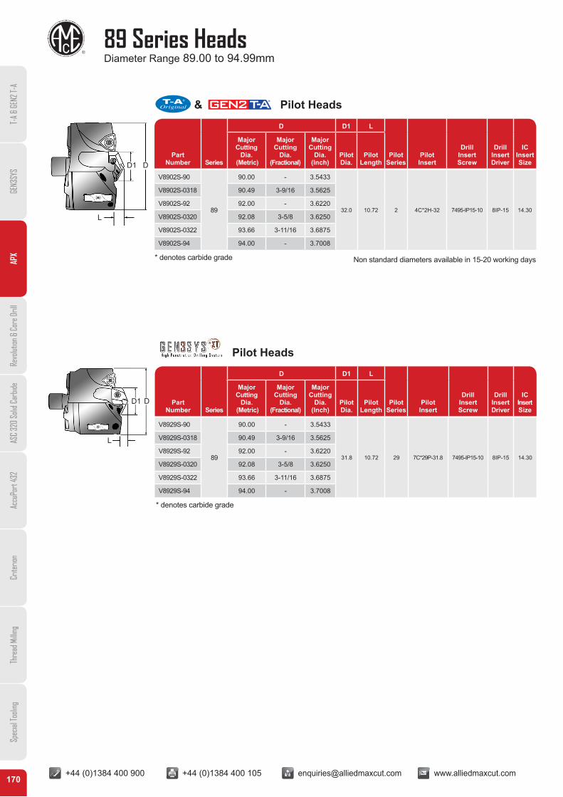
89 Series HeadsDiameter Range 89.00 to 94.99mm
170
Part Number Series
D D1 L
PilotSeries
Pilot Insert
Drill Insert Screw
Drill Insert Driver
IC Insert Size
Major Cutting
Dia. (Metric)
Major Cutting
Dia.(Fractional)
Major Cutting
Dia.(Inch)
Pilot Dia.
Pilot Length
PartNumber Series
D D1 L
PilotSeries
Pilot Insert
Drill Insert Screw
Drill Insert Driver
IC Insert Size
Major Cutting
Dia. (Metric)
Major Cutting
Dia.(Fractional)
Major Cutting
Dia.(Inch)
Pilot Dia.
Pilot Length
V8902S-90
89
90.00 - 3.5433
32.0 10.72 2 4C*2H-32 7495-IP15-10 8IP-15 14.30
V8902S-0318 90.49 3-9/16 3.5625
V8902S-92 92.00 - 3.6220
V8902S-0320 92.08 3-5/8 3.6250
V8902S-0322 93.66 3-11/16 3.6875
V8902S-94 94.00 - 3.7008
V8929S-90
89
90.00 - 3.5433
31.8 10.72 29 7C*29P-31.8 7495-IP15-10 8IP-15 14.30
V8929S-0318 90.49 3-9/16 3.5625
V8929S-92 92.00 - 3.6220
V8929S-0320 92.08 3-5/8 3.6250
V8929S-0322 93.66 3-11/16 3.6875
V8929S-94 94.00 - 3.7008
* denotes carbide grade
* denotes carbide grade
Non standard diameters available in 15-20 working days
D1 D
L
D1 D
L
T-A
& GE
N2 T-
AGE
N3SY
SAP
XRe
volut
ion &
Cor
e Dril
lAS
C 32
0 So
lid C
arbid
eAc
cuPo
rt 43
2Cr
iterio
nTh
read
Milli
ngSp
ecial
Tooli
ng
Pilot Heads
& Pilot Heads
+44 (0)1384 400 900 +44 (0)1384 400 105 [email protected] www.alliedmaxcut.com +44 (0)1384 400 900 +44 (0)1384 400 105 [email protected] www.alliedmaxcut.com
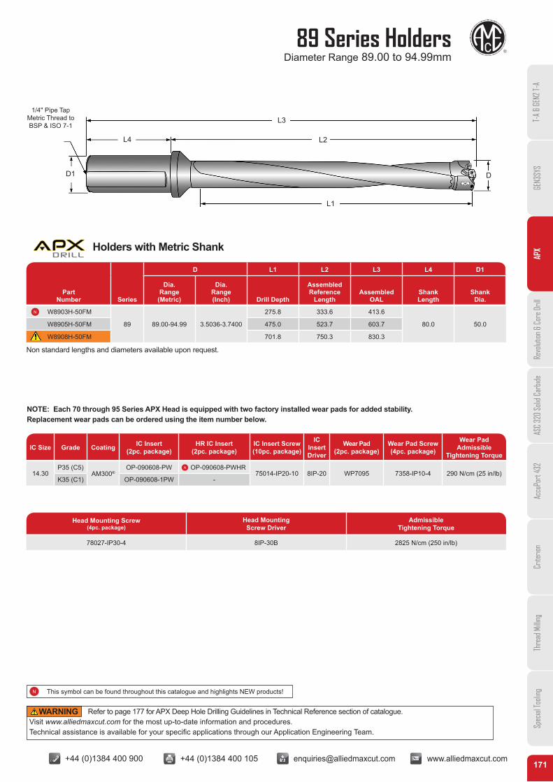
89 Series HoldersDiameter Range 89.00 to 94.99mm
171
IC Size Grade Coating IC Insert (2pc. package)
HR IC Insert (2pc. package)
IC Insert Screw(10pc. package)
IC Insert Driver
Wear Pad (2pc. package)
Wear Pad Screw (4pc. package)
Wear Pad Admissible
Tightening Torque
14.30P35 (C5)
AM300®OP-090608-PW OP-090608-PWHR
75014-IP20-10 8IP-20 WP7095 7358-IP10-4 290 N/cm (25 in/lb)K35 (C1) OP-090608-1PW -
NOTE: Each 70 through 95 Series APX Head is equipped with two factory installed wear pads for added stability. Replacement wear pads can be ordered using the item number below.
Part Number Series
D L1 L2 L3 L4 D1
Dia. Range (Metric)
Dia. Range (Inch) Drill Depth
AssembledReference
LengthAssembled
OALShankLength
ShankDia.
W8903H-50FM
89 89.00-94.99 3.5036-3.7400
275.8 333.6 413.6
80.0 50.0W8905H-50FM 475.0 523.7 603.7
W8908H-50FM 701.8 750.3 830.3
Head Mounting Screw(4pc. package)
Head Mounting Screw Driver
Admissible Tightening Torque
78027-IP30-4 8IP-30B 2825 N/cm (250 in/lb)
Non standard lengths and diameters available upon request.
D
L1
L2
L3
D1
L4
1/4" Pipe TapMetric Thread to BSP & ISO 7-1
T-A
& GE
N2 T-
AGE
N3SY
SAP
XRe
volut
ion &
Cor
e Dril
lAS
C 32
0 So
lid C
arbid
eAc
cuPo
rt 43
2Cr
iterio
nTh
read
Milli
ngSp
ecial
Tooli
ng
Holders with Metric Shank
Refer to page 177 for APX Deep Hole Drilling Guidelines in Technical Reference section of catalogue. Visit www.alliedmaxcut.com for the most up-to-date information and procedures. Technical assistance is available for your specific applications through our Application Engineering Team.
WARNING
This symbol can be found throughout this catalogue and highlights NEW products!

+44 (0)1384 400 900 +44 (0)1384 400 105 [email protected] www.alliedmaxcut.com +44 (0)1384 400 900 +44 (0)1384 400 105 [email protected] www.alliedmaxcut.com
95 Series HeadsDiameter Range 95.00 to 101.60mm
172
PartNumber Series
D D1 L
PilotSeries
Pilot Insert
Drill Insert Screw
Drill Insert Driver
IC Insert Size
Major Cutting
Dia. (Metric)
Major Cutting
Dia.(Fractional)
Major Cutting
Dia.(Inch)
Pilot Dia.
Pilot Length
Part Number Series
D D1 L
PilotSeries
Pilot Insert
Drill Insert Screw
Drill Insert Driver
IC Insert Size
Major Cutting
Dia. (Metric)
Major Cutting
Dia.(Fractional)
Major Cutting
Dia.(Inch)
Pilot Dia.
Pilot Length
V9502S-0324
95
95.25 3-3/4 3.7500
35.0 11.51 2 4C*2H-35 7494-IP15-10 8IP-15 14.30
V9502S-96 96.00 - 3.7795
V9502S-0326 96.84 3-13/16 3.8125
V9502S-98 98.00 - 3.8583
V9502S-0328 98.43 3-7/8 3.8750
V9502S-100 100.00 - 3.9370
V9502S-0330 100.01 3-15/16 3.9375
V9502S-0400 101.60 4 4.0000
V9532S-0324
95
95.25 3-3/4 3.7500
35.0 11.51 32 7C*32P-35 7494-IP15-10 8IP-15 14.30
V9532S-96 96.00 - 3.7795
V9532S-0326 96.84 3-13/16 3.8125
V9532S-98 98.00 - 3.8583
V9532S-0328 98.43 3-7/8 3.8750
V9532S-100 100.00 - 3.9370
V9532S-0330 100.01 3-15/16 3.9375
V9532S-0400 101.60 4 4.0000
* denotes carbide grade
* denotes carbide grade
Non standard diameters available in 15-20 working days
D1 D
L
D1 D
L
T-A
& GE
N2 T-
AGE
N3SY
SAP
XRe
volut
ion &
Cor
e Dril
lAS
C 32
0 So
lid C
arbid
eAc
cuPo
rt 43
2Cr
iterio
nTh
read
Milli
ngSp
ecial
Tooli
ng
Pilot Heads
& Pilot Heads
+44 (0)1384 400 900 +44 (0)1384 400 105 [email protected] www.alliedmaxcut.com +44 (0)1384 400 900 +44 (0)1384 400 105 [email protected] www.alliedmaxcut.com
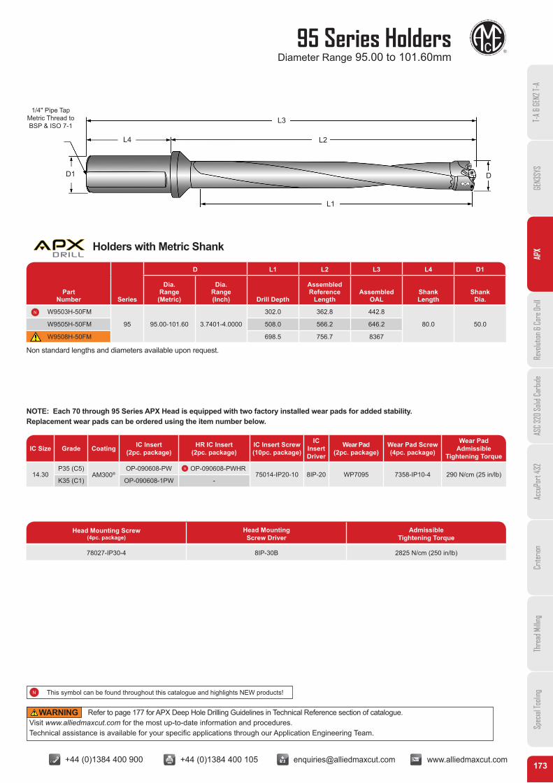
95 Series HoldersDiameter Range 95.00 to 101.60mm
173
IC Size Grade Coating IC Insert (2pc. package)
HR IC Insert (2pc. package)
IC Insert Screw (10pc. package)
IC Insert Driver
Wear Pad (2pc. package)
Wear Pad Screw (4pc. package)
Wear Pad Admissible
Tightening Torque
14.30P35 (C5)
AM300®OP-090608-PW OP-090608-PWHR
75014-IP20-10 8IP-20 WP7095 7358-IP10-4 290 N/cm (25 in/lb)K35 (C1) OP-090608-1PW -
NOTE: Each 70 through 95 Series APX Head is equipped with two factory installed wear pads for added stability. Replacement wear pads can be ordered using the item number below.
Part Number Series
D L1 L2 L3 L4 D1
Dia. Range (Metric)
Dia. Range (Inch) Drill Depth
AssembledReference
LengthAssembled
OALShankLength
ShankDia.
W9503H-50FM
95 95.00-101.60 3.7401-4.0000
302.0 362.8 442.8
80.0 50.0W9505H-50FM 508.0 566.2 646.2
W9508H-50FM 698.5 756.7 8367
Head Mounting Screw (4pc. package)
Head Mounting Screw Driver
Admissible Tightening Torque
78027-IP30-4 8IP-30B 2825 N/cm (250 in/lb)
Non standard lengths and diameters available upon request.
D
L1
L2
L3
D1
L4
1/4" Pipe TapMetric Thread to BSP & ISO 7-1
T-A
& GE
N2 T-
AGE
N3SY
SAP
XRe
volut
ion &
Cor
e Dril
lAS
C 32
0 So
lid C
arbid
eAc
cuPo
rt 43
2Cr
iterio
nTh
read
Milli
ngSp
ecial
Tooli
ng
Holders with Metric Shank
Refer to page 177 for APX Deep Hole Drilling Guidelines in Technical Reference section of catalogue. Visit www.alliedmaxcut.com for the most up-to-date information and procedures. Technical assistance is available for your specific applications through our Application Engineering Team.
WARNING
This symbol can be found throughout this catalogue and highlights NEW products!
+44 (0)1384 400 900 +44 (0)1384 400 105 [email protected] www.alliedmaxcut.com +44 (0)1384 400 900 +44 (0)1384 400 105 [email protected] www.alliedmaxcut.com
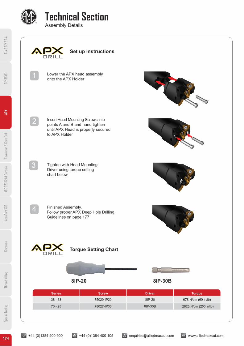
Technical SectionAssembly Details
174
Lower the APX head assembly onto the APX Holder
Insert Head Mounting Screws into points A and B and hand tighten until APX Head is properly secured to APX Holder
Tighten with Head Mounting Driver using torque setting chart below
Finished Assembly. Follow proper APX Deep Hole Drilling Guidelines on page 177
AB
Series Screw Driver Torque
38 - 63 75020-IP20 8IP-20 678 N/cm (60 in/lb)
70 - 95 78027-IP30 8IP-30B 2825 N/cm (250 in/lb)
Torque Setting Chart
Set up instructions
8IP-20 8IP-30B
1
2
3
4
T-A
& GE
N2 T-
AGE
N3SY
SAP
XRe
volut
ion &
Cor
e Dril
lAS
C 32
0 So
lid C
arbid
eAc
cuPo
rt 43
2Cr
iterio
nTh
read
Milli
ngSp
ecial
Tooli
ng
+44 (0)1384 400 900 +44 (0)1384 400 105 [email protected] www.alliedmaxcut.com +44 (0)1384 400 900 +44 (0)1384 400 105 [email protected] www.alliedmaxcut.com
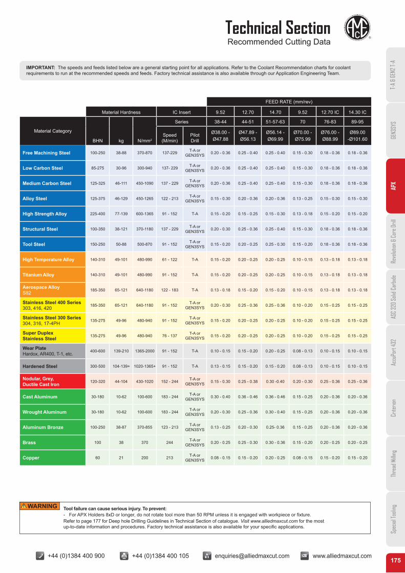
Technical SectionRecommended Cutting Data
175
IMPORTANT: The speeds and feeds listed below are a general starting point for all applications. Refer to the Coolant Recommendation charts for coolant requirements to run at the recommended speeds and feeds. Factory technical assistance is also available through our Application Engineering Team.
FEED RATE (mm/rev)
Material Hardness IC Insert 9.52 12.70 14.70 9.52 12.70 IC 14.30 IC
Material Category
BHN kg N/mm2
Series 38-44 44-51 51-57-63 70 76-83 89-95
Speed (M/min)
Pilot Drill
Ø38.00 - Ø47.88
Ø47.89 - Ø56.13
Ø56.14 - Ø69.99
Ø70.00 - Ø75.99
Ø76.00 - Ø88.99
Ø89.00 -Ø101.60
Free Machining Steel 100-250 38-88 370-870 137-229 T-A or GEN3SYS 0.20 - 0.36 0.25 - 0.40 0.25 - 0.40 0.15 - 0.30 0.18 - 0.36 0.18 - 0.36
Low Carbon Steel 85-275 30-96 300-940 137- 229 T-A or GEN3SYS 0.20 - 0.36 0.25 - 0.40 0.25 - 0.40 0.15 - 0.30 0.18 - 0.36 0.18 - 0.36
Medium Carbon Steel 125-325 46-111 450-1090 137 - 229 T-A or GEN3SYS 0.20 - 0.36 0.25 - 0.40 0.25 - 0.40 0.15 - 0.30 0.18 - 0.36 0.18 - 0.36
Alloy Steel 125-375 46-129 450-1265 122 - 213 T-A or GEN3SYS 0.15 - 0.30 0.20 - 0.36 0.20 - 0.36 0.13 - 0.25 0.15 - 0.30 0.15 - 0.30
High Strength Alloy 225-400 77-139 600-1365 91 - 152 T-A 0.15 - 0.20 0.15 - 0.25 0.15 - 0.30 0.13 - 0.18 0.15 - 0.20 0.15 - 0.20
Structural Steel 100-350 38-121 370-1180 137 - 229 T-A or GEN3SYS 0.20 - 0.30 0.25 - 0.36 0.25 - 0.40 0.15 - 0.30 0.18 - 0.36 0.18 - 0.36
Tool Steel 150-250 50-88 500-870 91 - 152 T-A or GEN3SYS 0.15 - 0.20 0.20 - 0.25 0.25 - 0.30 0.15 - 0.20 0.18 - 0.36 0.18 - 0.36
High Temperature Alloy 140-310 49-101 480-990 61 - 122 T-A 0.15 - 0.20 0.20 - 0.25 0.20 - 0.25 0.10 - 0.15 0.13 - 0.18 0.13 - 0.18
Titanium Alloy 140-310 49-101 480-990 91 - 152 T-A 0.15 - 0.20 0.20 - 0.25 0.20 - 0.25 0.10 - 0.15 0.13 - 0.18 0.13 - 0.18
Aerospace AlloyS82 185-350 65-121 640-1180 122 - 183 T-A 0.13 - 0.18 0.15 - 0.20 0.15 - 0.20 0.10 - 0.15 0.13 - 0.18 0.13 - 0.18
Stainless Steel 400 Series303, 416, 420 185-350 65-121 640-1180 91 - 152 T-A or
GEN3SYS 0.20 - 0.30 0.25 - 0.36 0.25 - 0.36 0.10 - 0.20 0.15 - 0.25 0.15 - 0.25
Stainless Steel 300 Series304, 316, 17-4PH 135-275 49-96 480-940 91 - 152 T-A or
GEN3SYS 0.15 - 0.20 0.20 - 0.25 0.20 - 0.25 0.10 - 0.20 0.15 - 0.25 0.15 - 0.25
Super Duplex Stainless Steel 135-275 49-96 480-940 76 - 137 T-A or
GEN3SYS 0.15 - 0.20 0.20 - 0.25 0.20 - 0.25 0.10 - 0.20 0.15 - 0.25 0.15 - 0.25
Wear PlateHardox, AR400, T-1, etc. 400-600 139-210 1365-2000 91 - 152 T-A 0.10 - 0.15 0.15 - 0.20 0.20 - 0.25 0.08 - 0.13 0.10 - 0.15 0.10 - 0.15
Hardened Steel 300-500 104-139+ 1020-1365+ 91 - 152 T-A 0.13 - 0.15 0.15 - 0.20 0.15 - 0.20 0.08 - 0.13 0.10 - 0.15 0.10 - 0.15
Nodular, Grey, Ductile Cast Iron 120-320 44-104 430-1020 152 - 244 T-A or
GEN3SYS 0.15 - 0.30 0.25 - 0.38 0.30 -0.40 0.20 - 0.30 0.25 - 0.36 0.25 - 0.36
Cast Aluminum 30-180 10-62 100-600 183 - 244 T-A or GEN3SYS 0.30 - 0.40 0.36 - 0.46 0.36 - 0.46 0.15 - 0.25 0.20 - 0.36 0.20 - 0.36
Wrought Aluminum 30-180 10-62 100-600 183 - 244 T-A or GEN3SYS 0.20 - 0.30 0.25 - 0.36 0.30 - 0.40 0.15 - 0.25 0.20 - 0.36 0.20 - 0.36
Aluminum Bronze 100-250 38-87 370-855 123 - 213 T-A or GEN3SYS 0.13 - 0.25 0.20 - 0.30 0.25- 0.36 0.15 - 0.25 0.20 - 0.36 0.20 - 0.36
Brass 100 38 370 244 T-A or GEN3SYS 0.20 - 0.25 0.25 - 0.30 0.30 - 0.36 0.15 - 0.20 0.20 - 0.25 0.20 - 0.25
Copper 60 21 200 213 T-A or GEN3SYS 0.08 - 0.15 0.15 - 0.20 0.20 - 0.25 0.08 - 0.15 0.15 - 0.20 0.15 - 0.20
Tool failure can cause serious injury. To prevent:- For APX Holders 8xD or longer, do not rotate tool more than 50 RPM unless it is engaged with workpiece or fixture.Refer to page 177 for Deep hole Drilling Guidelines in Technical Section of catalogue. Visit www.alliedmaxcut.com for the most up-to-date information and procedures. Factory technical assistance is also available for your specific applications.
WARNING
T-A
& GE
N2 T-
AGE
N3SY
SAP
XRe
volut
ion &
Cor
e Dril
lAS
C 32
0 So
lid C
arbid
eAc
cuPo
rt 43
2Cr
iterio
nTh
read
Milli
ngSp
ecial
Tooli
ng

+44 (0)1384 400 900 +44 (0)1384 400 105 [email protected] www.alliedmaxcut.com +44 (0)1384 400 900 +44 (0)1384 400 105 [email protected] www.alliedmaxcut.com
Technical SectionChip Enhancing Geometries
176
IMPORTANT: The coolant pressure and flow rate recommendations below represent a good approximation to obtain optimum tool life and chip evacuation at Allied recommended speeds and feeds. If lower coolant capabilities exist in a drilling application, the APX Drilling System will still function at reduced penetration rates. Contact our Application Engineering Department for a more specific recommendation of coolant requirements and/or speeds and feeds.
Insert Guidelines
T-A® Original
Standard T-A® : Allied’s Standard T-A® Geometry is an excellent choice for general purpose use. The design provides fast penetration rates that produce good hole size and finish. Standard Geometry combines highly efficient, stable cutting action to minimize power consumption. Recommended for use in most steels, cast irons, high temperature alloys and aluminum alloys.
GEN2 T-A® : For more stable applications with good rigidity to take advantage of the centering notch point geometry and increased efficiency. Offers improved tool life verses Standard T-A®. Recommended for most steels and cast iron. GEN2 T-A® High Elasticity (HE) : Allied’s GEN2 T-A® HE Geometry is designed for improved chip formation in elastic materials like low carbon steels. HE Geometry combined with the other advanced features of the GEN2 T-A®, allows for maximum performance and increased value. Available in K35 with AM200® Coating.
TC : Allied’s TC geometry is an excellent choice for applications that are running at lighter feed rates, or require a more manageable chip. Recommended for use in low carbon steels, soft alloy steels, and other long chipping materials. Available in K35 with AM200® Coating.
GEN3SYS® XT
GEN3SYS® XT offers superior chip forming capabilities and material specific geometries such as (-AS), which is designed for austinetic stainless steels.
AS : Enhanced AS-XT geometry improves chip control in Austentic stainless steel. Stronger point geometry improves penetration rates. First choice for austenitic stainless steels. AM300® coating provides exceptional wear resistance and up to 20% increase in tool life over AM200®. Tough K20 grade. LR : Enhanced LR-XT geometry supports applications with poor stability and rigidity. First choice for machining structural, cast and forged steel in materials over 850N/mm² (250BHN). AM300® coating provides exceptional wear resistance and up to 20% increase in tool life over AM200®. Available in K35 & K20 grades. STD : XT geometry - first choice for steels, alloys and hardened materials. Optimum chip formation in elastic materials, with improved penetration rates. AM300® coating provides exceptional wear resistance and up to 20% increase in tool life over AM200®. Available in K35 & K20 grades.
SeriesPressure Flow Rate
BAR PSI LPM GPM
38 21 300 38 10
44 19 275 45 12
51 17 250 68 18
57 16 225 76 20
63 14 200 83 22
70 10 150 95 25
76 7 100 106 28
83 7 100 114 30
89 7 100 125 33
95 7 100 125 33
T-A
& GE
N2 T-
AGE
N3SY
SAP
XRe
volut
ion &
Cor
e Dril
lAS
C 32
0 So
lid C
arbid
eAc
cuPo
rt 43
2Cr
iterio
nTh
read
Milli
ngSp
ecial
Tooli
ng
+44 (0)1384 400 900 +44 (0)1384 400 105 [email protected] www.alliedmaxcut.com +44 (0)1384 400 900 +44 (0)1384 400 105 [email protected] www.alliedmaxcut.com
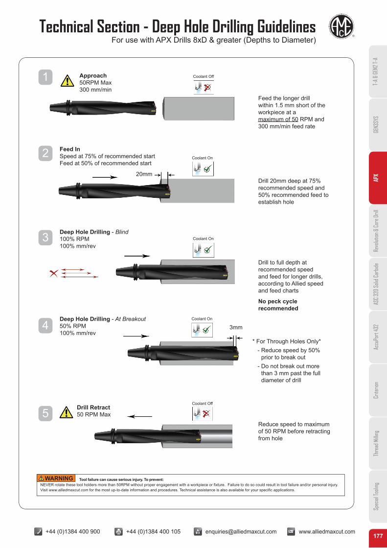
Technical Section - Deep Hole Drilling GuidelinesFor use with APX Drills 8xD & greater (Depths to Diameter)
177
Tool failure can cause serious injury. To prevent:NEVER rotate these tool holders more than 50RPM without proper engagement with a workpiece or fixture. Failure to do so could result in tool failure and/or personal injury.Visit www.alliedmaxcut.com for the most up-to-date information and procedures. Technical assistance is also available for your specific applications.
WARNING
Feed the longer drill within 1.5 mm short of the workpiece at a maximum of 50 RPM and 300 mm/min feed rate
Drill 20mm deep at 75% recommended speed and 50% recommended feed to establish hole
Drill to full depth at recommended speed and feed for longer drills, according to Allied speed and feed charts
No peck cycle recommended
* For Through Holes Only* - Reduce speed by 50%
prior to break out - Do not break out more
than 3 mm past the full diameter of drill
Reduce speed to maximum of 50 RPM before retracting from hole
Approach 50RPM Max 300 mm/min
Drill Retract 50 RPM Max
Feed In Speed at 75% of recommended start Feed at 50% of recommended start
Deep Hole Drilling - Blind 100% RPM 100% mm/rev
Deep Hole Drilling - At Breakout 50% RPM 100% mm/rev
Coolant Off
Coolant Off
Coolant On
Coolant On
Coolant On
20mm
1
2
3
4
5
3mm
T-A
& GE
N2 T-
AGE
N3SY
SAP
XRe
volut
ion &
Cor
e Dril
lAS
C 32
0 So
lid C
arbid
eAc
cuPo
rt 43
2Cr
iterio
nTh
read
Milli
ngSp
ecial
Tooli
ng

+44 (0)1384 400 900 +44 (0)1384 400 105 [email protected] www.alliedmaxcut.com +44 (0)1384 400 900 +44 (0)1384 400 105 [email protected] www.alliedmaxcut.com
Holder Accessories
178
InsertSeries
Part NumberMaximum
Torque (N/cm)TORX Plus®
Hand DriversTORX Plus®
Screws*Nylon LockingTORX Screws*
0 8IP-8 72556-IP8-10 72556N-IP8-10 175
1 8IP-9 7375-IP9-10 7375N-IP9-10 305
2 8IP-15 7495-IP15-10 7495N-IP15-10 690
InsertSeries
Part Number TORX PlusScrew
RecommendedTightening
Torque (N/cm)
TORX PlusHand Driver
Preset TorqueTORX PlusHand Driver
ReplacementTORX Plus
TipsTORX Plus
Screws*Nylon Locking
TORX PlusScrews*
15 8IP-7 8IP-7TL 8IP-7B 7247-IP7-10 7247N-IP7-10 84
17 8IP-8 8IP-8TL 8IP-8B 72567-IP8-10 72567N-IP8-10 175
18 8IP-9 8IP-9TL 8IP-9B 7375-IP9-10 7375N-IP9-10 305
20 8IP-9 8IP-9TL 8IP-9B 7375-IP9-10 7375N-IP9-10 305
22 8IP-9 8IP-9TL 8IP-9B 7375-IP9-10 7375N-IP9-10 305
24 8IP-9 8IP-9TL 8IP-9B 739-IP9-10 739N-IP9-10 305
26 8IP-15 8IP-15TL 8IP-15B 7495-IP15-10 7495N-IP15-10 690
29 8IP-15 8IP-15TL 8IP-15B 7495-IP15-10 7495N-IP15-10 690
32 8IP-15 8IP-15TL 8IP-15B 7495-IP15-10 7495N-IP15-10 690
T-A® Pilot Insert Replacement TORX Plus Screws and Driver information
GEN3SYS® XT Pilot Insert Replacement TORX Plus Screws and Driver information
* Tightening torques are calculated with a friction coefficient of μ = 0.14 and develops 90% of ultimate yield strength *Supplied in 10 piece packages.
*Supplied in 10 piece packages.
T-A
& GE
N2 T-
AGE
N3SY
SAP
XRe
volut
ion &
Cor
e Dril
lAS
C 32
0 So
lid C
arbid
eAc
cuPo
rt 43
2Cr
iterio
nTh
read
Milli
ngSp
ecial
Tooli
ng