
T-124 OMl and AG 1-PG - bicycles, tricycles, industrial ... · warning advices and instructions to...
36
INDUSTRIAL TRICYCLES
Transcript of T-124 OMl and AG 1-PG - bicycles, tricycles, industrial ... · warning advices and instructions to...
INDUSTRIAL TRICYCLES

2
3
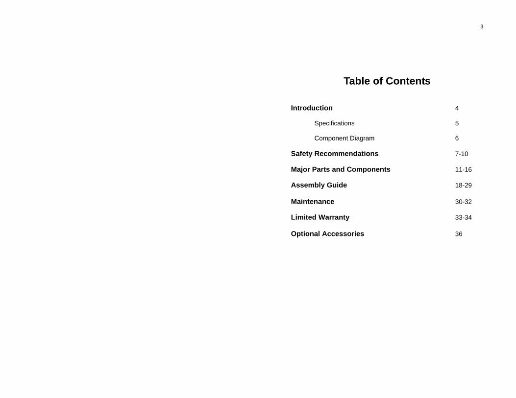
Table of Contents Introduction 4 Specifications 5 Component Diagram 6 Safety Recommendations 7-10 Major Parts and Components 11-16 Assembly Guide 18-29 Maintenance 30-32 Limited Warranty 33-34 Optional Accessories 36
4
Introduction Congratulations on you purchase of your new Husky industrial tricycle. You have purchased a tricycle that has many features and qualities. Please take a few minutes and read through this manual before you ride your tricycle for the first time. Learning about this tricycle and safe riding and maintenance will return many years of enjoyment and useful life. Throughout this manual, there are several safety notes, which we recommend you read very carefully. Riding a tricycle is a sport, and like many sports, it involves taking the risk of injury and damage. Since most injuries result from unsafe riding or lack of proper maintenance, this manual will focus on helping you learn about safe riding and how to keep your tricycle in good riding condition. This tricycle is designed for business and commercial use, but it is also suitable for recreational use The performance and life of this product vary based on usage, riding surface condition, environment, and carrying load weight. Proper maintenance, regular inspection and replacement of worn-out components will not only enhance the useful life and performance, but also will enhance the safety to rider.
SPECIFICATIONS
Model T-124C or T-326 Frame Size 16" (top of seat tube to center of crank)
WARNING! Cycling can be a hazardous activity. You are responsible for safe riding and proper maintenance of your tricycle. Failure to observe the safety rules and warnings throughout this manual may result in property damage, personal injury or death. There are warnings throughout this manual. Follow all warning advices and instructions to reduce the risk of injury or damage.
5
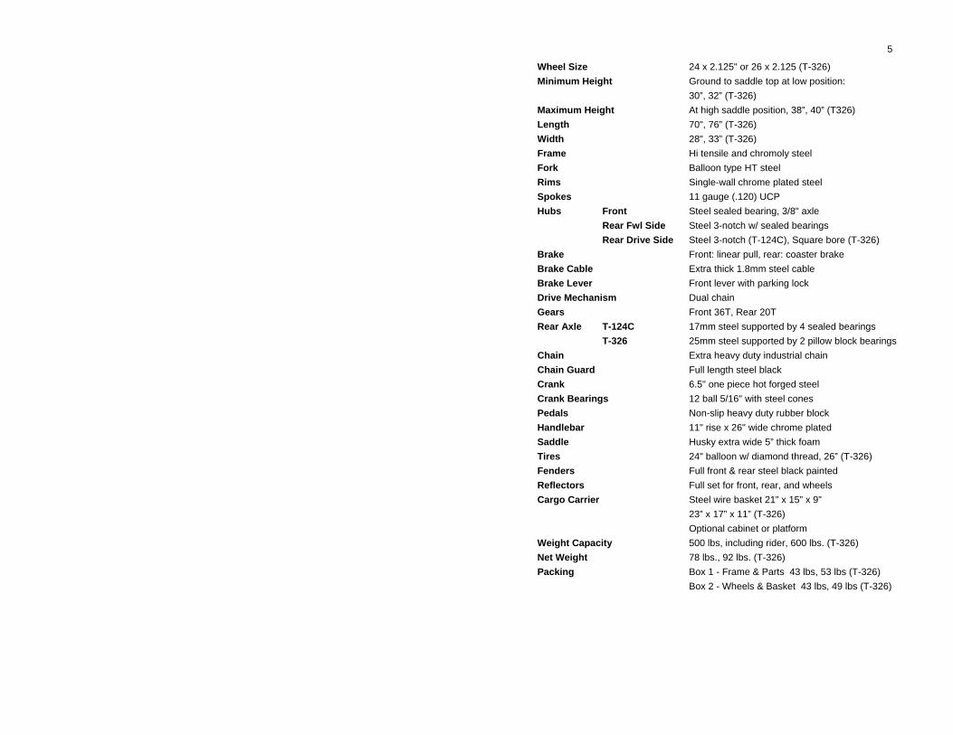
Wheel Size 24 x 2.125" or 26 x 2.125 (T-326) Minimum Height Ground to saddle top at low position: 30”, 32” (T-326) Maximum Height At high saddle position, 38”, 40” (T326) Length 70", 76” (T-326) Width 28", 33” (T-326) Frame Hi tensile and chromoly steel Fork Balloon type HT steel Rims Single-wall chrome plated steel Spokes 11 gauge (.120) UCP Hubs Front Steel sealed bearing, 3/8" axle Rear Fwl Side Steel 3-notch w/ sealed bearings Rear Drive Side Steel 3-notch (T-124C), Square bore (T-326) Brake Front: linear pull, rear: coaster brake Brake Cable Extra thick 1.8mm steel cable Brake Lever Front lever with parking lock Drive Mechanism Dual chain Gears Front 36T, Rear 20T Rear Axle T-124C 17mm steel supported by 4 sealed bearings T-326 25mm steel supported by 2 pillow block bearings Chain Extra heavy duty industrial chain Chain Guard Full length steel black Crank 6.5" one piece hot forged steel Crank Bearings 12 ball 5/16" with steel cones Pedals Non-slip heavy duty rubber block Handlebar 11" rise x 26" wide chrome plated Saddle Husky extra wide 5” thick foam Tires 24" balloon w/ diamond thread, 26” (T-326) Fenders Full front & rear steel black painted Reflectors Full set for front, rear, and wheels Cargo Carrier Steel wire basket 21” x 15” x 9” 23” x 17” x 11” (T-326) Optional cabinet or platform Weight Capacity 500 lbs, including rider, 600 lbs. (T-326) Net Weight 78 lbs., 92 lbs. (T-326) Packing Box 1 - Frame & Parts 43 lbs, 53 lbs (T-326) Box 2 - Wheels & Basket 43 lbs, 49 lbs (T-326)
6
7
SAFETY FIRST! ALWAYS WEAR A SAFETY HELMET - In a work place, we recommend wearing a helmet or hard hat while riding your tricycle. Make sure your helmet meets or exceeds ANSI and Snell safety standards. Look for standard certification label inside the helmet. RIDING WITHOUT A HELMET MAY RESULT IN SERIOUS INJURY IN THE EVENT OF AN ACCIDENT. KNOW ALL THE COMPONENTS OF THE TRICYCLE AND THEIR FUNCTION - In the next section of this manual, we have listed all the components and their functions. Read this section and familiarize yourself with these parts. ADJUST THE HEIGHT FOR BEST FIT - You can raise or lower the seat post according to your height. You can also tilt the handle bar back or forth for the most convenient position. LEARN BIKE RIDING THOROUGHLY BEFORE RIDING - Riding a tricycle does not require the balancing and coordination skills as in riding a bicycle. Nevertheless, you need to learn the basic concept of riding and familiarize yourself with special handling and riding techniques that are unique to this type of tricycle. Due to weight and size of these models, the condition of the surface on which you ride your tricycle affects the performance of your tricycle. You must learn to handle the tricycle in different surface conditions. Try riding the tricycle in low speed, steering the handlebar and experiencing the handling while performing different maneuvers. FAMILIARIZE YOURSELF WITH LOCAL AND STATE LAWS AND ORDINANCES - If you plan to ride your tricycle on the streets or public trails or bike routes, you must learn about the laws regulating bicycle riding as well as minimum safety equipment required. Most states and cities require the use of hand signals by all bicycle riders. Learn these signals and use them every time you are riding on a road or street. ALWAYS RIDE SINGLE FILE ON A ROAD OR STREET. If you plan to use tricycle in a work place where other workers and vehicles are present, we recommend you install safety devices such as horn, light, bell, mirror, and safety flag. Depending on the situation, you may need one or more of these safety devices so that you can alert others of your presence. Please contact your HUSKY dealer if you need more information on safety accessories.
8 CHECK YOUR TRICYCLE BEFORE YOU RIDE - Check the air pressure, ride the bike for a few minutes and check the brakes and other safety equipment. Make sure all components are securely attached. Pay particular attention to the saddle, handlebar, wheel axle nuts, and pedals. NEVER USE HEADPHONES OR DEVICES THAT MAY IMPAIR YOUR HEARING ABILITY WHILE RIDING A BIKE - In many states it is illegal to use headphones while riding a bicycle.
SAFE RIDING AT NIGHT We do not recommend riding your tricycle in dark. If you have to ride at night or in dark areas, please follow these rules: LIGHTS - You should equip your tricycle with a high quality bicycle head light for the front, usually mounted on the handle bar, and a blinking red light mounted on the rear, normally below the saddle. If the rear basket is installed, mount the rear light or reflector at the rear side of the basket where it is visible. REFLECTORS - Your tricycle is equipped with a set of reflectors, mounted on the front and rear as well as on the wheel spokes. Your tricycle should reflect light from all directions. Make sure your reflectors are clean and mounted correctly. Please refer to Major Standard Parts and Component section of this Manual for more information about the reflectors. Your bicycle also comes with reflector-mounted pedals. REFLECTIVE GEAR - We recommend you use additional reflective gear such as reflective safety vest, reflective helmet, or safety flag. Always wear light color apparel when riding at night. Remember, the objective is to see and be seen at distance when riding at night. SAFETY FLAGS - Safety flags are excellent for riding in high traffic areas. Mounted on the rear axle and extending about 6 feet above the ground, they allow others to spot a rider from far distance. Safety flags are available at your HUSKY dealers.
SAFE RIDING IN WET CONDITIONS You never know when you may get caught in a rainstorm or an afternoon summer shower. If you ride your tricycle in your work place, you may run into wet or slippery spots from time to time. Here are a few tips to help make riding in wet or slick condition safer:
9 RIDE SLOWLY! - Your brakes’ performance is greatly reduced in wet conditions. Lower speed helps you control the bike if you have to make a sudden brake. If you live in an area where there is frequent rain or showers, you may want to consult with your bicycle dealer about using tires more suitable for wet conditions. SPECIAL NOTE ON REAR COASTER BRAKE - Your tricycle is equipped with a rear coaster brake (foot brake). It is important that you minimize the chances of your foot slipping off the pedal when braking. Do not ride in standing position in wet condition. Wearing shoes with non-slip rubber soles or use of non-slip pedals is highly recommended for areas with high rate of precipitation. ENHANCE YOUR HANDLEBAR GRIP - The handlebar is the primary control component of your bicycle and you must be sure you have a firm grip of the handlebar in all conditions. Using gloves when riding your bike helps minimize loss of grip in wet conditions. FENDERS - HUSKY offers fenders as standard equipment for most of its products. Fenders protect the rider from water and mud splashes.
SAFE RIDING ON STREETS LEARN ABOUT YOUR STATE AND LOCAL BICYCLING LAWS - You should obtain a copy of your local and state bicycling laws. Many bike shops have a copy of the laws. You can also obtain a copy at your nearest highway patrol office or your area cycling club. Learn these laws thoroughly; they can save you life. DO NOT RIDE AGAINST TRAFFIC - Stay as far right as possible and allow room for cars to pass you as easily as possible. Try avoiding two-lane roads with narrow shoulder or highways with high traffic. RIDE DEFENSSIVELY - Always give right of way to autos, and never get into a contest with an automobile driver. Be on the look out for cars coming into the road from driveways, parking lots, or side streets. Make an eye contact with the driver to make sure he/she can see you. WATCH FOR PEDESTRIANS - Use your horn or bell to make sure pedestrians can hear you are coming or passing from behind. WATCH OUT FOR ROAD HAZARDS - One of the most common road hazards are pot holes, cracks in the asphalt or concrete pavement, railroad tracks, and objects such as rocks, wires, tree limbs, or sand and loose gravel. Any one of these hazards can cause you to lose control.
10 If necessary, dismount and walk your bike over or around the hazard. Do not ride on railroad tracks. BE CAREFUL AROUND PARKED CARS - When approaching parked cars, be on the look out for people getting in or out of parked cars. Allow a safe distance between your bike and parked cars with passengers to avoid possible collision with open doors. OBEY ALL TRAFFIC SIGNS - Stop at stop signs, red lights, and yield signs. Always use hand signals when turning or stopping. DO NOT HITCH A RIDE ON A BIKE - Never hold on to another vehicle in order to hitch a ride. DO NOT CARRY CHILDREN OR PETS IN THE CARGO AREA Cargo Carrying Recommendations Your Husky tricycle is designed to carry light cargo. Weight distribution of cargo is very important. Do not stack cargo too high. Whether you use a basket, platform, or trunk for carrying cargo, make sure that 75% of the weight is centered directly above the rear axle of the tricycle. Do not allow cargo to extend more than 10” beyond the edge of rear tires. Spread the load evenly in the cargo area and secure all loose parts or boxes. Basket liners help keep small parts and objects from falling through the basket. HUSKY offers an optional basket liner for model T-124C. Do not attempt to jump a curb or a speed bump. Riding on uneven surface or jumping curb may damage the frame or fork, especially when your tricycle is loaded.
WARNING!
Due to size and weight of Husky cargo tricycles, avoid narrow sidewalks and off-road bicycle trails. Also avoid roads or ramps with steep grade. When riding down a ramp or hill, exercise extreme caution and slow down, using both brakes. Avoid sharp turns at high speeds.
11
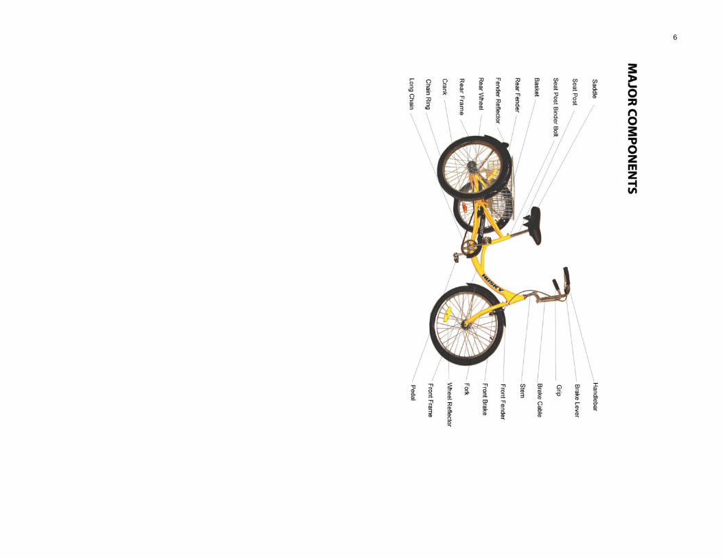
Major Parts and Components The following is a brief description of major parts and components and their functions.
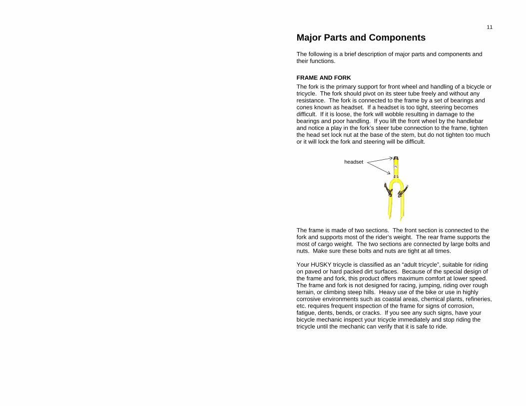
FRAME AND FORK The fork is the primary support for front wheel and handling of a bicycle or tricycle. The fork should pivot on its steer tube freely and without any resistance. The fork is connected to the frame by a set of bearings and cones known as headset. If a headset is too tight, steering becomes difficult. If it is loose, the fork will wobble resulting in damage to the bearings and poor handling. If you lift the front wheel by the handlebar and notice a play in the fork’s steer tube connection to the frame, tighten the head set lock nut at the base of the stem, but do not tighten too much or it will lock the fork and steering will be difficult. headset The frame is made of two sections. The front section is connected to the fork and supports most of the rider’s weight. The rear frame supports the most of cargo weight. The two sections are connected by large bolts and nuts. Make sure these bolts and nuts are tight at all times. Your HUSKY tricycle is classified as an “adult tricycle”, suitable for riding on paved or hard packed dirt surfaces. Because of the special design of the frame and fork, this product offers maximum comfort at lower speed. The frame and fork is not designed for racing, jumping, riding over rough terrain, or climbing steep hills. Heavy use of the bike or use in highly corrosive environments such as coastal areas, chemical plants, refineries, etc. requires frequent inspection of the frame for signs of corrosion, fatigue, dents, bends, or cracks. If you see any such signs, have your bicycle mechanic inspect your tricycle immediately and stop riding the tricycle until the mechanic can verify that it is safe to ride.
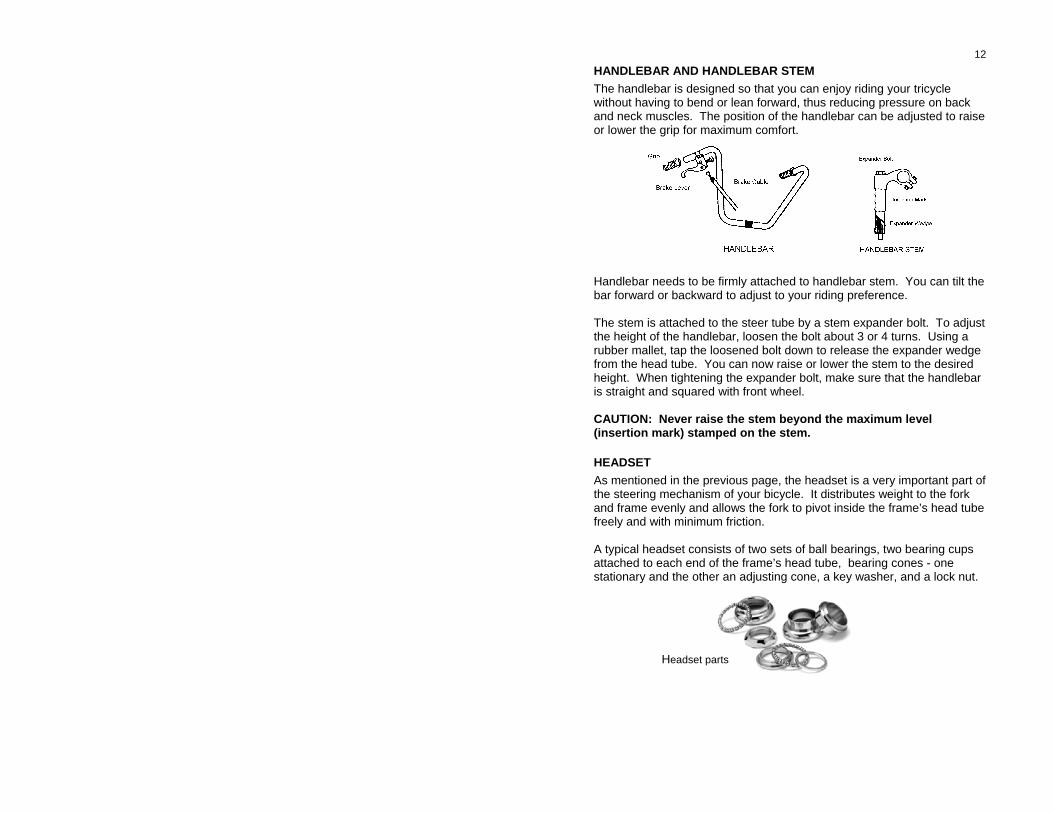
12 HANDLEBAR AND HANDLEBAR STEM The handlebar is designed so that you can enjoy riding your tricycle without having to bend or lean forward, thus reducing pressure on back and neck muscles. The position of the handlebar can be adjusted to raise or lower the grip for maximum comfort. Handlebar needs to be firmly attached to handlebar stem. You can tilt the bar forward or backward to adjust to your riding preference. The stem is attached to the steer tube by a stem expander bolt. To adjust the height of the handlebar, loosen the bolt about 3 or 4 turns. Using a rubber mallet, tap the loosened bolt down to release the expander wedge from the head tube. You can now raise or lower the stem to the desired height. When tightening the expander bolt, make sure that the handlebar is straight and squared with front wheel. CAUTION: Never raise the stem beyond the maximum level (insertion mark) stamped on the stem.
HEADSET As mentioned in the previous page, the headset is a very important part of the steering mechanism of your bicycle. It distributes weight to the fork and frame evenly and allows the fork to pivot inside the frame’s head tube freely and with minimum friction. A typical headset consists of two sets of ball bearings, two bearing cups attached to each end of the frame’s head tube, bearing cones - one stationary and the other an adjusting cone, a key washer, and a lock nut.
Headset parts
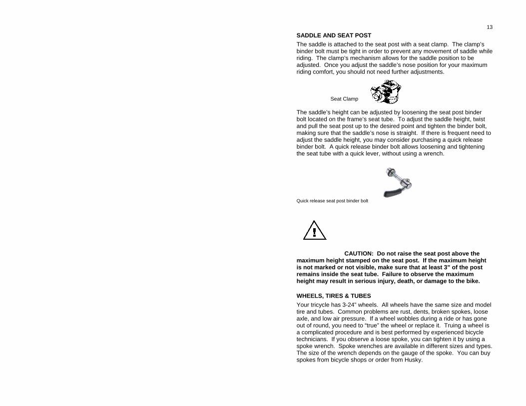
13 SADDLE AND SEAT POST The saddle is attached to the seat post with a seat clamp. The clamp’s binder bolt must be tight in order to prevent any movement of saddle while riding. The clamp’s mechanism allows for the saddle position to be adjusted. Once you adjust the saddle’s nose position for your maximum riding comfort, you should not need further adjustments. Seat Clamp The saddle’s height can be adjusted by loosening the seat post binder bolt located on the frame’s seat tube. To adjust the saddle height, twist and pull the seat post up to the desired point and tighten the binder bolt, making sure that the saddle’s nose is straight. If there is frequent need to adjust the saddle height, you may consider purchasing a quick release binder bolt. A quick release binder bolt allows loosening and tightening the seat tube with a quick lever, without using a wrench. Quick release seat post binder bolt CAUTION: Do not raise the seat post above the maximum height stamped on the seat post. If the maximum height is not marked or not visible, make sure that at least 3” of the post remains inside the seat tube. Failure to observe the maximum height may result in serious injury, death, or damage to the bike.
WHEELS, TIRES & TUBES Your tricycle has 3-24” wheels. All wheels have the same size and model tire and tubes. Common problems are rust, dents, broken spokes, loose axle, and low air pressure. If a wheel wobbles during a ride or has gone out of round, you need to “true” the wheel or replace it. Truing a wheel is a complicated procedure and is best performed by experienced bicycle technicians. If you observe a loose spoke, you can tighten it by using a spoke wrench. Spoke wrenches are available in different sizes and types. The size of the wrench depends on the gauge of the spoke. You can buy spokes from bicycle shops or order from Husky.
14 Check your tires by observing any cuts or cracks on the side wall, air pressure, and amount of wear on the thread. A worn-out tire is not safe for riding and is more vulnerable to road hazards.
PEDALS Your bicycle is equipped with a set of pedals. Pedals should spin freely around the center spindle, which is attached to the crank arms. If pedals fail to spin or the spindle is not tightly attached to the crank arm, do not ride the bike until the pedal is secured to the crank arm.
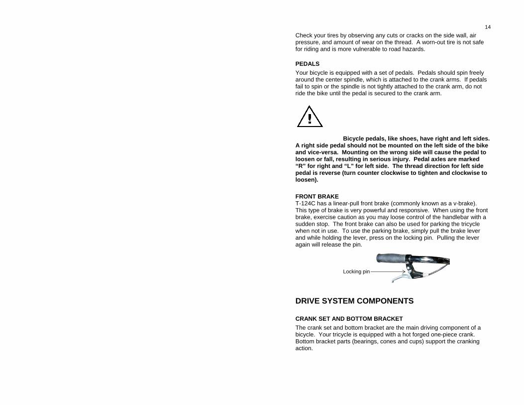
Bicycle pedals, like shoes, have right and left sides. A right side pedal should not be mounted on the left side of the bike and vice-versa. Mounting on the wrong side will cause the pedal to loosen or fall, resulting in serious injury. Pedal axles are marked “R” for right and “L” for left side. The thread direction for left side pedal is reverse (turn counter clockwise to tighten and clockwise to loosen). FRONT BRAKE T-124C has a linear-pull front brake (commonly known as a v-brake). This type of brake is very powerful and responsive. When using the front brake, exercise caution as you may loose control of the handlebar with a sudden stop. The front brake can also be used for parking the tricycle when not in use. To use the parking brake, simply pull the brake lever and while holding the lever, press on the locking pin. Pulling the lever again will release the pin. Locking pin
DRIVE SYSTEM COMPONENTS
CRANK SET AND BOTTOM BRACKET The crank set and bottom bracket are the main driving component of a bicycle. Your tricycle is equipped with a hot forged one-piece crank. Bottom bracket parts (bearings, cones and cups) support the cranking action.
15 The crank and bottom bracket parts must be secure. As with the headset and fork, the crank should spin on its axle through the bottom bracket freely and without any friction or resistance. To test the cranking action, have someone lift the rear end of the tricycle. You should be able to crank the bike and spin the right-side rear wheel with one hand. If you are not able to crank using one hand or you feel too much resistance, or if the crank wobbles inside the bottom bracket, you may have a component failure in your drive system or need to adjust the bolts and nuts. Have the bicycle inspected by a mechanic. CAUTION: Keep your hands and fingers away from the spinning wheel, the moving chain, or the sprockets at all times to prevent injury.
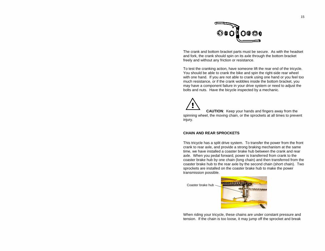
CHAIN AND REAR SPROCKETS This tricycle has a split drive system. To transfer the power from the front crank to rear axle, and provide a strong braking mechanism at the same time, we have installed a coaster brake hub between the crank and rear axle. When you pedal forward, power is transferred from crank to the coaster brake hub by one chain (long chain) and then transferred from the coaster brake hub to the rear axle by the second chain (short chain). Two sprockets are installed on the coaster brake hub to make the power transmission possible. Coaster brake hub When riding your tricycle, these chains are under constant pressure and tension. If the chain is too loose, it may jump off the sprocket and break
16 the link between the crank set and rear wheel. If the chain is too tight, it may warp the crank set, damage the coaster brake, or the bottom bracket bearings. Too much tension on the small chain can cause excess wear on the rear axle and axle sprocket. The chain guard protects your legs and clothes from contact with moving chain and sprocket. If you hear rattling during when riding the tricycle, the chain may be rubbing against the chain guard. You can eliminate the noise by adjusting the chain guard.
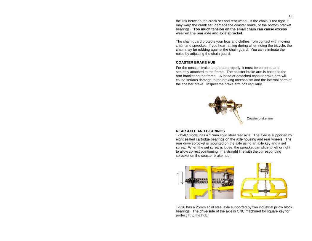
COASTER BRAKE HUB For the coaster brake to operate properly, it must be centered and securely attached to the frame. The coaster brake arm is bolted to the arm bracket on the frame. A loose or detached coaster brake arm will cause serious damage to the braking mechanism and the internal parts of the coaster brake. Inspect the brake arm bolt regularly. Coaster brake arm REAR AXLE AND BEARINGS T-124C model has a 17mm solid steel rear axle. The axle is supported by eight sealed cartridge bearings on the axle housing and rear wheels. The rear drive sprocket is mounted on the axle using an axle key and a set screw. When the set screw is loose, the sprocket can slide to left or right to allow correct positioning, in a straight line with the corresponding sprocket on the coaster brake hub. T-326 has a 25mm solid steel axle supported by two industrial pillow block bearings. The drive-side of the axle is CNC machined for square key for perfect fit to the hub.
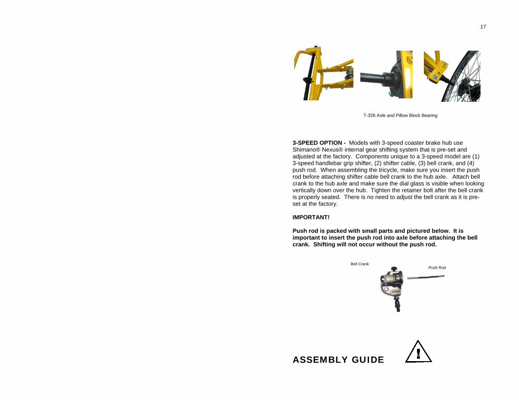
17 T-326 Axle and Pillow Block Bearing 3-SPEED OPTION - Models with 3-speed coaster brake hub use Shimano® Nexus® internal gear shifting system that is pre-set and adjusted at the factory. Components unique to a 3-speed model are (1) 3-speed handlebar grip shifter, (2) shifter cable, (3) bell crank, and (4) push rod. When assembling the tricycle, make sure you insert the push rod before attaching shifter cable bell crank to the hub axle. Attach bell crank to the hub axle and make sure the dial glass is visible when looking vertically down over the hub. Tighten the retainer bolt after the bell crank is properly seated. There is no need to adjust the bell crank as it is pre-set at the factory. IMPORTANT! Push rod is packed with small parts and pictured below. It is important to insert the push rod into axle before attaching the bell crank. Shifting will not occur without the push rod.
ASSEMBLY GUIDE
Bell Crank Push Rod
18
This assembly guide is intended for use by bicycle technicians or experienced mechanics.
HUSKY ASSUMES THAT THE PERSON ASSEMBLING THIS PRODUCT HAS THE BASIC KNOWLEDGE OF PROPER ASSEMBLY AND AJUSTMENT OF A BICYCLE.
THIS ASSEMBLY GUIDE ONLY PROVIDES THE BASIC STEPS IN ASSEMBLING THIS PRODUCT. PROPER ADJUSTMENT, TIGHTENING TORQUE OF BOLTS AND NUTS, PROPER FITTING TO THE SIZE AND HEIGHT OF RIDER IS NOT COVERED BY THIS MANUAL.
To properly assemble and adjust the components to achieve the best and safest ride, we strongly recommend that you ask your dealer to arrange for the installation of this product or take it to your nearest bicycle dealer.
IMPROPER OR INCORRECT ASSEMBLY OF THIS PRODUCT MAY RESULT IN DAMAGE OR LOSS OF PROPERTY, INJURY OR DEATH.
EXCESSIVE WEAR OR DAMAGE TO THE PARTS OR COMPONENTS DUE TO INCORRECT ASSEMBLY IS NOT COVERED UNDER WARRANTY.
HUSKY BICYCLES DOES NOT ASSUME ANY RESPONSIBILITY FOR FAILURE OF THIS PRODUCT, PROPERTY DAMAGE, OR INJURY OR DEATH DUE TO INCORRECT OR IMPROPER ASSEMBLY.
FOR QUESTIONS OR ASSISTANCE REGARDING THE ASSEMBLY OF THIS PRODUCT, PLEASE CONTACT HUSKY BICYCLES, L.L.C. AT (800) 392-3337, MONDAY - FRIDAY BETWEEN 8:30 AM - 5:30 PM CST.
TOOLS NEEDED 1. 10, 13, 14, 15, and 22 mm box wrench 2. 10, 13, 14, 15, and 22 mm open end wrench 3. Phillips and flat-head screwdriver
19
4. Wire cutter 5. 4, 5, 6, and 8mm Allen Wrench 6. Bicycle Pump or air compressor There are 4 basic steps in assembly. They are: STEP 1 - Connecting front and rear sections of the frame, STEP 2 - Installing the wheels and fenders, STEP 3 - Installing saddle, handlebar, and pedals, and STEP 4 - Finishing work and test ride. BEFORE YOU BEGIN THE ASSEMBLY 1. Remove the components and parts from both boxes. 2. Identify the components and parts and check against the packing list on the next page. 3. Unpack the small parts bag, separating the bolts, nuts and washers and grouping them by size. 4. Set the following components aside for steps 3 and 4: Saddle Seat Post Pedals Handlebar and grips Brake lever and cable Chain guard Reflectors Rear Hub Caps (T-124) TO PREVENT DENT OR SCRATCH TO PAINTED PARTS, DO NOT REMOVE PROTECTIVE PADING AND WRAPS UNTIL AFTER THE ASSEMBLY IS COMPLETE.
PACKING LIST Your tricycle has been packed into two boxes, Frame Box and Wheels/Basket Box. On the side of the Frame Box, you will find
20
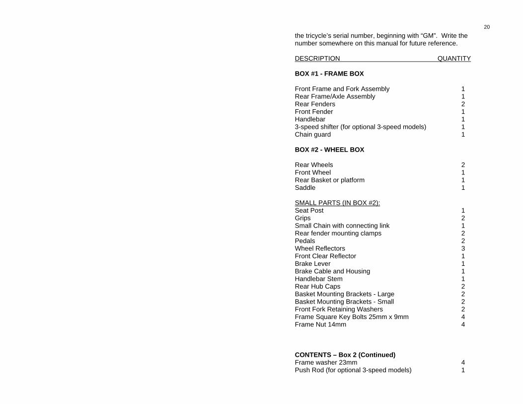
the tricycle’s serial number, beginning with “GM”. Write the number somewhere on this manual for future reference. DESCRIPTION QUANTITY BOX #1 - FRAME BOX Front Frame and Fork Assembly 1 Rear Frame/Axle Assembly 1 Rear Fenders 2 Front Fender 1 Handlebar 1 3-speed shifter (for optional 3-speed models) 1 Chain guard 1 BOX #2 - WHEEL BOX Rear Wheels 2 Front Wheel 1 Rear Basket or platform 1 Saddle 1 SMALL PARTS (IN BOX #2): Seat Post 1 Grips 2 Small Chain with connecting link 1 Rear fender mounting clamps 2 Pedals 2 Wheel Reflectors 3 Front Clear Reflector 1 Brake Lever 1 Brake Cable and Housing 1 Handlebar Stem 1 Rear Hub Caps 2 Basket Mounting Brackets - Large 2 Basket Mounting Brackets - Small 2 Front Fork Retaining Washers 2 Frame Square Key Bolts 25mm x 9mm 4 Frame Nut 14mm 4 CONTENTS – Box 2 (Continued) Frame washer 23mm 4 Push Rod (for optional 3-speed models) 1
21
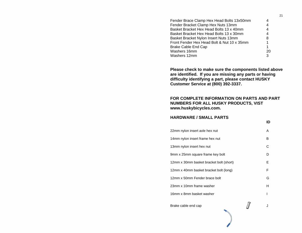
Fender Brace Clamp Hex Head Bolts 13x50mm 4 Fender Bracket Clamp Hex Nuts 13mm 4 Basket Bracket Hex Head Bolts 13 x 40mm 4 Basket Bracket Hex Head Bolts 13 x 30mm 4 Basket Bracket Nylon Insert Nuts 13mm 8 Front Fender Hex Head Bolt & Nut 10 x 35mm 1 Brake Cable End Cap 1 Washers 16mm 20 Washers 12mm 3 Please check to make sure the components listed above are identified. If you are missing any parts or having difficulty identifying a part, please contact HUSKY Customer Service at (800) 392-3337. FOR COMPLETE INFORMATION ON PARTS AND PART NUMBERS FOR ALL HUSKY PRODUCTS, VIST www.huskybicycles.com. HARDWARE / SMALL PARTS ID 22mm nylon insert axle hex nut A 14mm nylon insert frame hex nut B 13mm nylon insert hex nut C 9mm x 25mm square frame key bolt D 12mm x 30mm basket bracket bolt (short) E 12mm x 40mm basket bracket bolt (long) F 12mm x 50mm Fender brace bolt G 23mm x 10mm frame washer H 16mm x 8mm basket washer I Brake cable end cap J
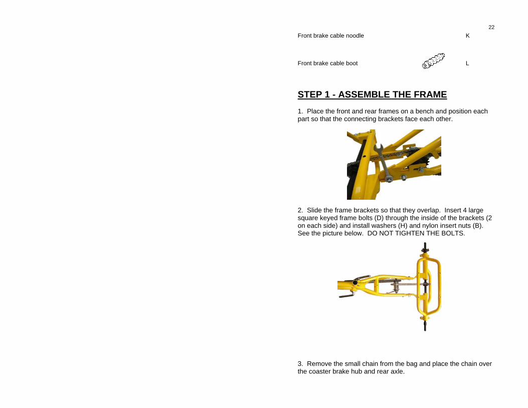
22 Front brake cable noodle K Front brake cable boot L STEP 1 - ASSEMBLE THE FRAME 1. Place the front and rear frames on a bench and position each part so that the connecting brackets face each other. 2. Slide the frame brackets so that they overlap. Insert 4 large square keyed frame bolts (D) through the inside of the brackets (2 on each side) and install washers (H) and nylon insert nuts (B). See the picture below. DO NOT TIGHTEN THE BOLTS. 3. Remove the small chain from the bag and place the chain over the coaster brake hub and rear axle.
23
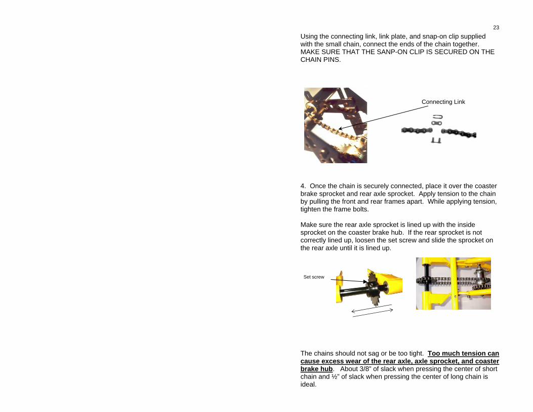
Using the connecting link, link plate, and snap-on clip supplied with the small chain, connect the ends of the chain together. MAKE SURE THAT THE SANP-ON CLIP IS SECURED ON THE CHAIN PINS. Connecting Link 4. Once the chain is securely connected, place it over the coaster brake sprocket and rear axle sprocket. Apply tension to the chain by pulling the front and rear frames apart. While applying tension, tighten the frame bolts. Make sure the rear axle sprocket is lined up with the inside sprocket on the coaster brake hub. If the rear sprocket is not correctly lined up, loosen the set screw and slide the sprocket on the rear axle until it is lined up. Set screw The chains should not sag or be too tight. Too much tension can cause excess wear of the rear axle, axle sprocket, and coaster brake hub. About 3/8” of slack when pressing the center of short chain and ½” of slack when pressing the center of long chain is ideal.
24
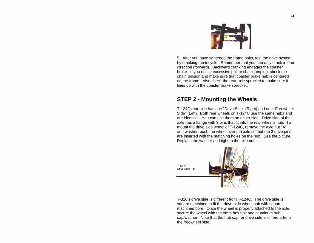
5. After you have tightened the frame bolts, test the drive system by cranking the tricycle. Remember that you can only crank in one direction (forward). Backward cranking engages the coaster brake. If you notice excessive pull or chain jumping, check the chain tension and make sure that coaster brake hub is centered on the frame. Also check the rear axle sprocket to make sure it lines up with the coaster brake sprocket. STEP 2 - Mounting the Wheels T-124C rear axle has one "Drive Side" (Right) and one "Freewheel Side" (Left). Both rear wheels on T-124C use the same hubs and are identical. You can use them on either side. Drive side of the axle has a flange with 3 pins that fit into the rear wheel’s hub. To mount the drive side wheel of T-124C, remove the axle nut "A" and washer, push the wheel over the axle so that the 3 drive pins are inserted with the matching holes on the hub. See the picture. Replace the washer and tighten the axle nut. T-124C Drive Side Pin T-326’s drive side is different from T-124C. The drive side is square machined to fit the drive-side wheel hub with square machined bore. Once the wheel is properly attached to the axle, secure the wheel with the 8mm hex bolt and aluminum hub cap/washer. Note that the hub cap for drive side is different from the freewheel side.
25
Drive-side axle and wheel Drive-side Hub Cap & Bolt Freewheel-side Hub Cap & Bolt Mount freewheel side wheel on the left axle. Make sure that the spacer is placed between the wheel's sealed bearing and axle bearing (for T-124C only). T-326 does not require a spacer washer. Replace the washer and tighten the axle nut. Spacer T-124C Freewheel side T-326 Freewheel side Before mounting the front wheel, attach the front fender to the fork and secure the two fender braces to the front fork using the machine screws on the fork's dropouts. Mount the wheel on the front fork. Once you have mounted the wheel, tighten the axle nuts. STEP 3 - Handlebar, Brake, Pedals, Saddle HANDLEBAR - Attach the handlebar stem by inserting it into head tube. Adjust the stem height but DO NOT EXTEND BEYOND "MINIMUM" MARK. Secure the stem bolt but do not tighten yet.
26
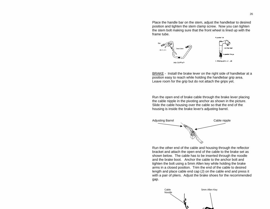
Place the handle bar on the stem, adjust the handlebar to desired position and tighten the stem clamp screw. Now you can tighten the stem bolt making sure that the front wheel is lined up with the frame tube. BRAKE - Install the brake lever on the right side of handlebar at a position easy to reach while holding the handlebar grip area. Leave room for the grip but do not attach the grips yet. Run the open end of brake cable through the brake lever placing the cable nipple in the pivoting anchor as shown in the picture. Slide the cable housing over the cable so that the end of the housing is inside the brake lever's adjusting barrel. Adjusting Barrel Cable nipple Run the other end of the cable and housing through the reflector bracket and attach the open end of the cable to the brake set as shown below. The cable has to be inserted through the noodle and the brake boot. Anchor the cable to the anchor bolt and tighten the bolt using a 5mm Allen key while holding the brake arms in a closed position. Trim the end of the cable to desired length and place cable end cap (J) on the cable end and press it with a pair of pliers. Adjust the brake shoes for the recommended gap.
Cable 5mm Allen Key Noodle
27
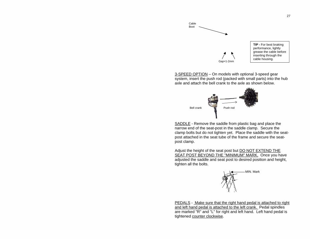
TIP - For best braking performance, lightly grease the cable before inserting through the cable housing.
Cable Boot
Gap=1-2mm 3-SPEED OPTION – On models with optional 3-speed gear system, insert the push rod (packed with small parts) into the hub axle and attach the bell crank to the axle as shown below. SADDLE - Remove the saddle from plastic bag and place the narrow end of the seat-post in the saddle clamp. Secure the clamp bolts but do not tighten yet. Place the saddle with the seat-post attached in the seat tube of the frame and secure the seat-post clamp. Adjust the height of the seat post but DO NOT EXTEND THE SEAT POST BEYOND THE "MINIMUM" MARK. Once you have adjusted the saddle and seat post to desired position and height, tighten all the bolts.
MIN. Mark
PEDALS - Make sure that the right hand pedal is attached to right and left hand pedal is attached to the left crank. Pedal spindles are marked "R" and "L" for right and left hand. Left hand pedal is tightened counter clockwise.
Bell crank Push rod
28
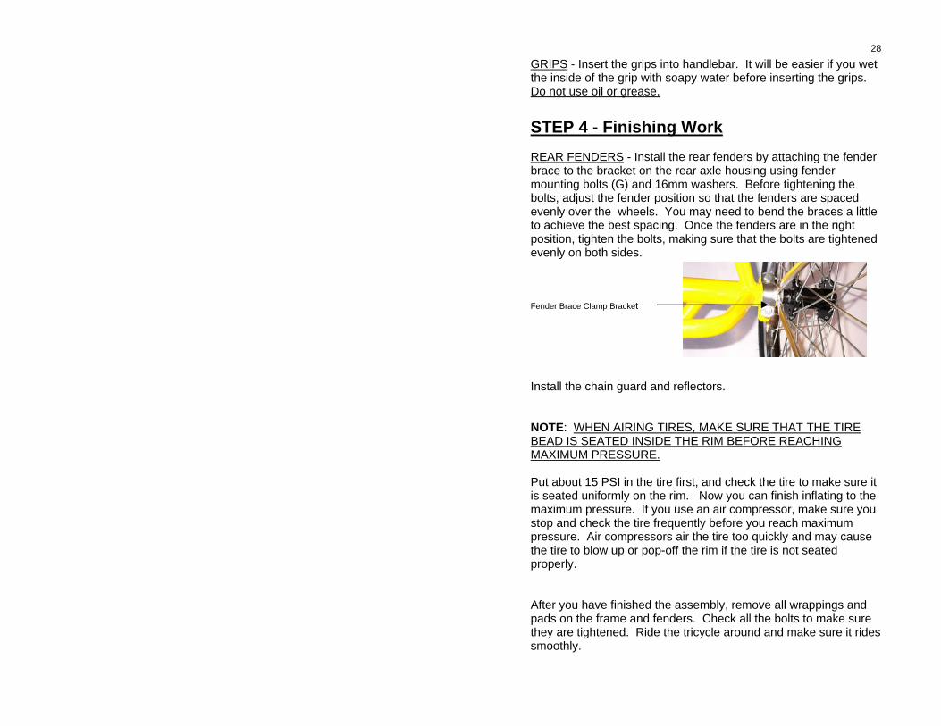
GRIPS - Insert the grips into handlebar. It will be easier if you wet the inside of the grip with soapy water before inserting the grips. Do not use oil or grease. STEP 4 - Finishing Work REAR FENDERS - Install the rear fenders by attaching the fender brace to the bracket on the rear axle housing using fender mounting bolts (G) and 16mm washers. Before tightening the bolts, adjust the fender position so that the fenders are spaced evenly over the wheels. You may need to bend the braces a little to achieve the best spacing. Once the fenders are in the right position, tighten the bolts, making sure that the bolts are tightened evenly on both sides. Fender Brace Clamp Bracket Install the chain guard and reflectors. NOTE: WHEN AIRING TIRES, MAKE SURE THAT THE TIRE BEAD IS SEATED INSIDE THE RIM BEFORE REACHING MAXIMUM PRESSURE. Put about 15 PSI in the tire first, and check the tire to make sure it is seated uniformly on the rim. Now you can finish inflating to the maximum pressure. If you use an air compressor, make sure you stop and check the tire frequently before you reach maximum pressure. Air compressors air the tire too quickly and may cause the tire to blow up or pop-off the rim if the tire is not seated properly. After you have finished the assembly, remove all wrappings and pads on the frame and fenders. Check all the bolts to make sure they are tightened. Ride the tricycle around and make sure it rides smoothly.
29
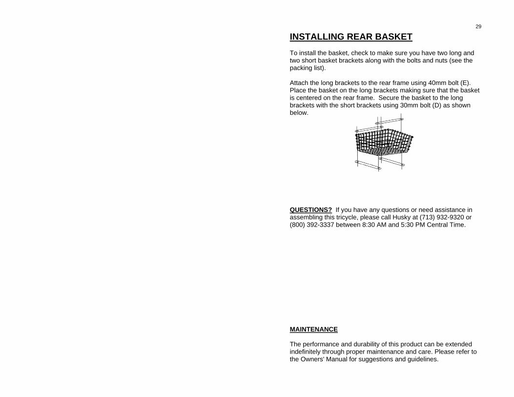
INSTALLING REAR BASKET To install the basket, check to make sure you have two long and two short basket brackets along with the bolts and nuts (see the packing list). Attach the long brackets to the rear frame using 40mm bolt (E). Place the basket on the long brackets making sure that the basket is centered on the rear frame. Secure the basket to the long brackets with the short brackets using 30mm bolt (D) as shown below. QUESTIONS? If you have any questions or need assistance in assembling this tricycle, please call Husky at (713) 932-9320 or (800) 392-3337 between 8:30 AM and 5:30 PM Central Time. MAINTENANCE The performance and durability of this product can be extended indefinitely through proper maintenance and care. Please refer to the Owners' Manual for suggestions and guidelines.
30
BASIC MAINTENANCE You have made a wise decision on purchasing a HUSKY tricycle. To make sure that it stays in good condition for many years of service and riding pleasure, we suggest the following:
CLEANING AND LUBRICATION Keeping your tricycle clean not only enhances the appearance of your bike, but also helps maintain the performance of vital components. The following is the recommended procedure for cleaning your bike: 1. Do not wipe off dry dirt or mud as it can scratch the painted surface.
First wet your bike thoroughly with clean water, and then wipe off dirt with a sponge or cloth.
2. Remove loose dirt on the gears, chain, hubs and wheels. 3. Wipe off wet parts with a clean dry cloth. 4. Excess grease or gum deposits on chain and sprockets can be
cleaned using chain cleaning fluids and degreasers available at your Husky dealer or hardware stores.
All moving components of the bike require lubrication. Certain components such as headset, bottom bracket, and hub bearings should be taken apart by an experienced bicycle technician and lubricated with special bearing grease. Oil or other lubricants for such parts should not be used.
You can lubricate the chain using special chain lubricants available at your authorized HUSKY dealer. Refer to the lubricant manufacturer’s instructions for proper application.
ROUTINE MAINTENANCE If you a do-it-yourselfer, possess technical skills, and have the proper tools for repair or maintenance of your bike, you can perform most basic routine maintenance such as lubrication, tire/tube maintenance, adjusting chain tension, and tightening loose nuts and bolts. Special attention should be given to crank locknut and coaster brake axle nuts. We do recommend that you take your bicycle to an authorized HUSKY dealer for
31 all major adjustments, wheel alignment and truing, component replacement, tire repair or replacement. If you ride your tricycle for more than 120 hours a month, we recommend that you follow a regular inspection and maintenance schedule. Consult with your authorized HUSKY dealer for a maintenance schedule that fit your riding style and time.
FIXING A FLAT TIRE There will be a time when you need to fix a flat tire. You can either take the bike to a bicycle shop or fix the flat yourself. You can fix a flat following these simple steps: TOOLS NEEDED: 2 tire levers, one frame mounted bicycle pump, axle nut wrench, a rag or cloth, and a tube patch kit. 1. Remove the wheel with a flat tire. If you are removing the front
wheel, you will need to disconnect the front brake cable and brake arm from the fork.
2. Open the valve and squeeze the remaining air out of the tube. To
open the valve, using a small screwdriver or tip of a tire lever, press on the valve pin.
3. Loosen the tire bead from the rime by squeezing the flat tire and
pushing it inward. Repeat this all around the tire, making sure that the bead is loose.
4. Pry one side of the tire bead up over the edge and insert the tire lever
under the bead by about 1/4”. DO NOT USE ANY LEVERS WITH SHARP POINTS SUCH AS A SCREW DRIVER OR A KNIFE.
5. Pull the tube from under the tire, leaving the tire on the rim.
If you are on the road with a flat tire, we recommend you carry a spare tube with you. It is much more convenient. You can patch the flat tube later when you get back home and keep it for later use.
6. Follow patch kit’s instructions for patching the leak. Inflate the tube
before putting the tube back to check for any other leaks. If no other leaks are found, deflate the tube. Dismount the tire from the rim.
Feel around the inside of the tire to find the cause. Check the rim for any damage or sharp objects. Wipe the rim and inside the tire clean.
7. Work one side of the tire over the edge of the rim. The other side
should hang out. Inflate the tube slightly to form a round shape.
32 Start working the tube under the tire by first inserting the valve into the valve hole.
8. When the tube is mounted over the rim and under one side of the tire,
try pushing the other side of tire bead over the edge of the rim. Once you reach the last 2 inches use the palm of your hand to slide the rest of the tire over the rim. Try not using the tire lever at this time as the lever can pinch the tube and cause a puncture. Most tires can be mounted on the rim without the use of a tool.
9. Check the bead of the tire and make sure you do not see any part of
the tube left out or pinched under. The bead must be seated within the wall of the rim.
10. Inflate the tire by pumping 4 or 5 strokes. Check the tire seating and
make sure the bead is not hanging out of the edge of the rim. 11. You can now inflate the tire to the proper pressure indicated on the
sidewall. If you do not have a pressure gauge, inflate until you cannot press the tire in more than 1/8”.
12. Screw the valve cap on the valve and install the wheel back on the
bike. When installing the front wheel, make sure that the wheel is centered on the fork as you tighten the axle nuts.
REPLACING FRONT BRAKE SHOES A worn-out brake shoe must be replaced as soon as the depth of rubber thread is 1/8" or less. To replace the shoes, remove the nuts and washer using a 5mm Allen wrench. When replacing the shoes, leave about 1mm gap between the shoes and the wheel's side-wall. Also make sure that the shoes are centered on the side-wall. BRAKE SHOES MUST NOT RUB AGAINST THE TIRE OR HANG BELLOW THE WHEEL'S SIDE-WALL.
VISIT www.huskybicycles.com to find parts and accessories for your Husky tricycle.
HUSKY LIMITED WARRANTY Husky T-124C is warranted to be free from defects in materials and workmanship with the following limitation:
TIME PERIOD
33 This warranty covers defective parts, materials, and labor for a period of one year from the date of original retail purchase. Proof of original retail purchase from an authorized HUSKY dealer is required on all warranty claims.
EXCLUSIONS This warranty does not cover:
• Normal wear and tear to parts and components, • Damage to the tricycle caused by casualty, accident, misuse,
neglect, abuse, improper assembly, improper repair, modification of any parts and components, or failure to follow the instructions in this manual.
• This tricycle is not designed for racing, jumping, stunt riding, or high speed down hill riding. Any damage or failure to the parts or components as a result of such activities is not covered by this warranty.
• Any bending of the fork, frame, handlebar, seat post, or rims, as a result of overloading, misuse, or modification of any parts or components are not covered by this warranty.
LIMITED WARRANTY This is the only warranty offered for your HUSKY Bicycle. There are no other warranties, whether express or implied by operation of law or otherwise, including but not limited to any express or implied warranties of merchantability, fitness to specific use, or performance.
HUSKY’s liability under this warranty is expressly limited to the replacement of defective parts and labor to correct any defect or failure, or at HUSKY’s sole election, replace the defective product.
HUSKY shall, in no event, be liable for any incidental or consequential damages, losses, or expenses with connection with this bicycle.
Some of the foregoing limitations or exclusions may not apply to you if you purchased your bicycle in a state where some or all of such limitations or exclusions are not permitted.
MAKING A WARRANTY CLAIM To make a claim under this warranty, follow these steps:
1. Do not perform any repair or replacement of any parts until an authorized HUSKY dealer inspects your tricycle or the dealer or
34 manufacturer authorizes such replacement. Repair of the bicycle during the warranty period by anyone other than an authorized HUSKY dealer may void the warranty.
2. Take your tricycle to an authorized HUSKY dealer together with the original copy of the proof of purchase. No warranty work can be performed without presenting the proof of purchase. The cost of transportation of the bicycle to and from an authorized HUSKY dealer is the responsibility of the owner.
3. HUSKY, at its sole option, may repair or replace the defective product. In the even HUSKY decides to repair the defect or replace the defective part, the work will be performed based on parts and labor availability. Husky reserves the right to substitute parts or components of different make or origin for the defective parts.
4. Warranty work shall not extend the original warranty period. However, parts and components replaced under this warranty are guaranteed to be free of defect for a period of one year from the date of installation. If you have any questions about the warranty policy, see your authorized HUSKY dealer or send an email to HUSKY Bicycles, at [email protected].
OWNER’S RECORD Serial Number ______________________ Date of Purchase ______________________ Dealer ______________________ Dealer Address ______________________
_____________________ Dealer Phone Number ______________________
35
36
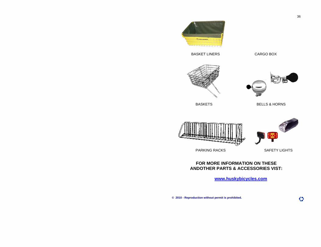
BASKET LINERS CARGO BOX BASKETS BELLS & HORNS PARKING RACKS SAFETY LIGHTS FOR MORE INFORMATION ON THESE
ANDOTHER PARTS & ACCESSORIES VIST:
www.huskybicycles.com
© 2010 - Reproduction without permit is prohibited.


![Welcome [] · 2019-08-05 · OML 1 OML 2 OML 3 OML 4 OML 5 Technology Standards Standards not defined without goal to standardize. ... to last replication interval Virtual Machine](https://static.fdocuments.in/doc/165x107/5f330ca087e5a327623269bd/welcome-2019-08-05-oml-1-oml-2-oml-3-oml-4-oml-5-technology-standards-standards.jpg)
