Sytronix – variable-speed pump drives - tehnodel.rs · Pumps 70 Accessories 79. 4 Bosch ......
82
Sytronix – variable-speed pump drives Energy-efficient | Intelligent | Cost-effective
-
Upload
nguyendiep -
Category
Documents
-
view
233 -
download
0
Transcript of Sytronix – variable-speed pump drives - tehnodel.rs · Pumps 70 Accessories 79. 4 Bosch ......
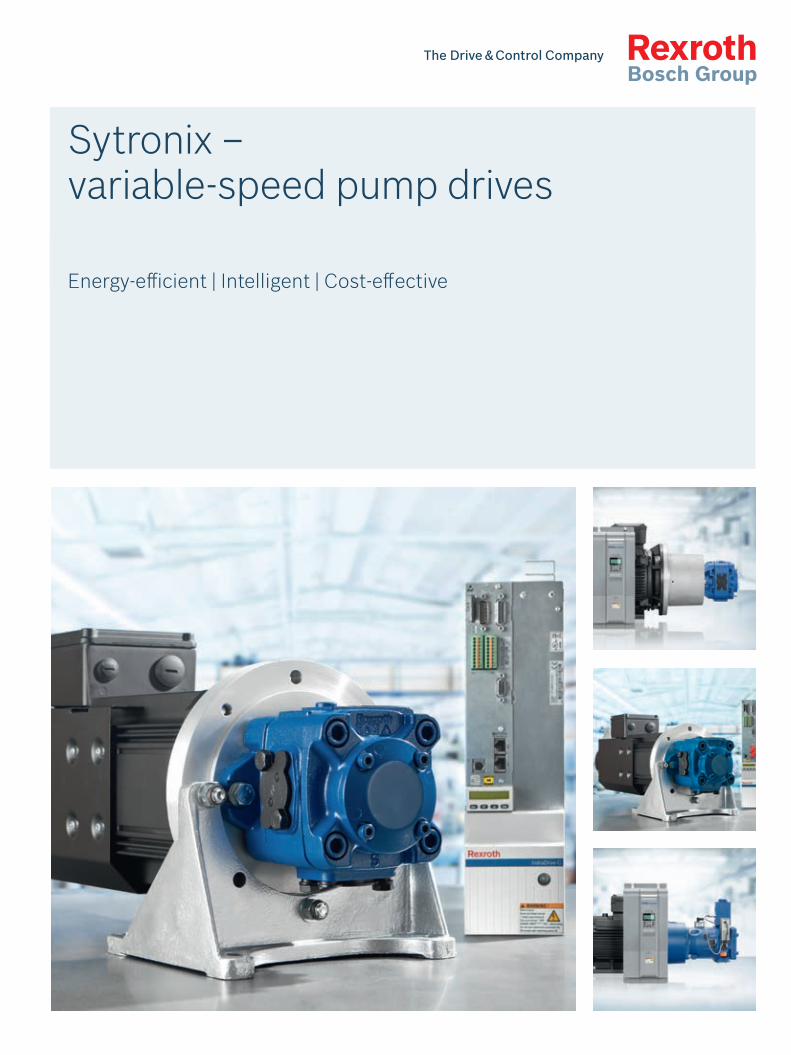
Sytronix – variable-speed pump drives
Energy-efficient | Intelligent | Cost-effective

3
R999000332, 2015-08, Bosch Rexroth AG
Sytronix pump drive systems
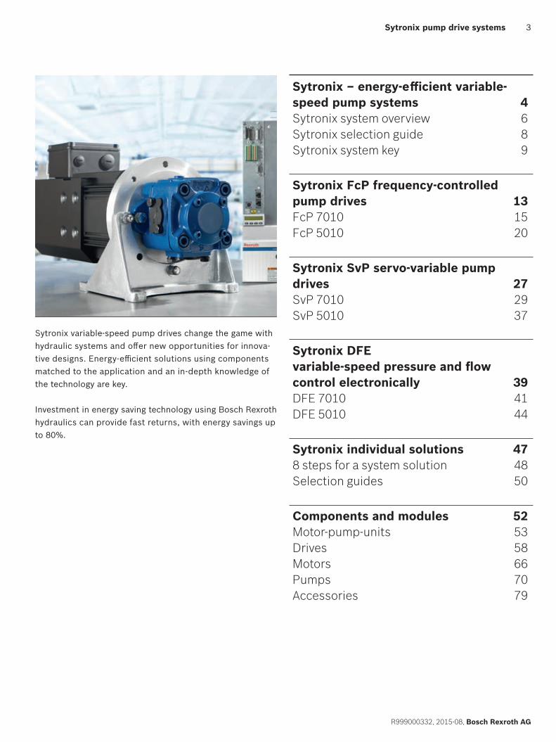
Sytronix variable-speed pump drives change the game with hydraulic systems and offer new opportunities for innova-tive designs. Energy-efficient solutions using components matched to the application and an in-depth knowledge of the technology are key.
Investment in energy saving technology using Bosch Rexroth hydraulics can provide fast returns, with energy savings up to 80%.
Sytronix – energy-efficient variable-speed pump systems 4Sytronix system overview 6Sytronix selection guide 8Sytronix system key 9
Sytronix FcP frequency-controlled pump drives 13FcP 7010 15FcP 5010 20
Sytronix SvP servo-variable pump drives 27SvP 7010 29SvP 5010 37
Sytronix DFE variable-speed pressure and flow control electronically 39DFE 7010 41DFE 5010 44
Sytronix individual solutions 478 steps for a system solution 48Selection guides 50
Components and modules 52Motor-pump-units 53Drives 58Motors 66Pumps 70Accessories 79
4
Bosch Rexroth AG, R999000332, 2015-08
Sytronix pump drive systems
Sytronix – energy-efficient variable-speed pump systems
Older machine designs focused on systems that had the capacity to deliver maximum performance, even though it might have only been for a fraction of the total cycle. Today there is a greater emphasis on reducing energy consumption and noise emissions. Higher energy prices and workplace environmental requirements have engineers rethinking their designs.
Using Sytronix (smart interplay of hydraulics and electronics) variable-speed pump drives can address these issues by combining the advantages of Bosch Rexroth technologies: reliability of high-performance hydraulics and energy-effi-ciency and dynamics of high-performance drives and elec-tronics.
Sytronix drives combine matched electric motors, hydraulic pumps, and VFDs (variable frequency drives), which has the potential of significant energy savings and a considerable reduction in noise emissions at a cost that provides an attractive return on investment.
Energy on Demand – powerful hydraulics, intelligent controlBy integrating the advantages of hydraulics with the control intelligence of electrical drives, motor speeds can be continu-ally adjusted to match the machine’s requirements. The drive speed of the pump can be lowered to an energy-efficient, quiet level when the process requires less than full performance. By having a major portion of the machine cycle time matched to the part-load requirement, energy is saved and noise is reduced.
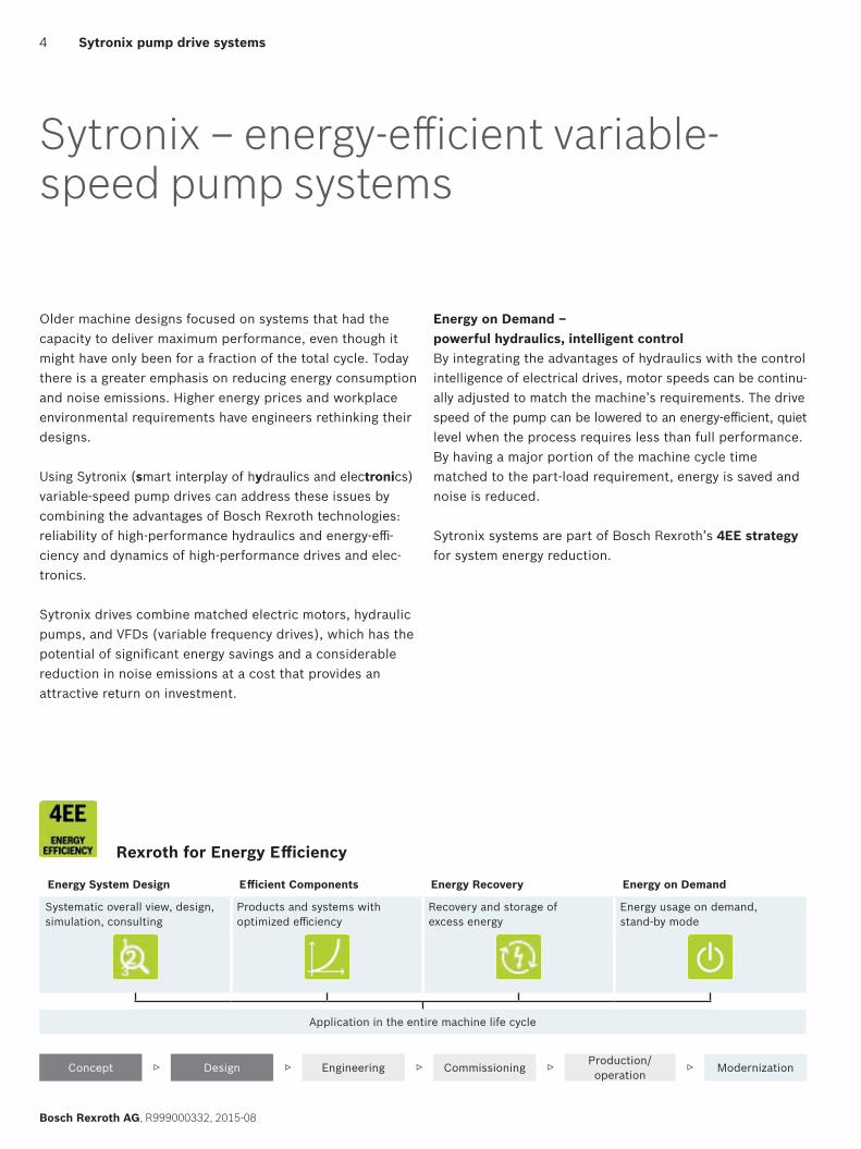
Sytronix systems are part of Bosch Rexroth’s 4EE strategy for system energy reduction.
Rexroth for Energy Efficiency
Energy System Design Efficient Components Energy Recovery Energy on Demand
Systematic overall view, design, simulation, consulting
Products and systems with optimized efficiency
Recovery and storage of excess energy
Energy usage on demand, stand-by mode
Application in the entire machine life cycle
Concept ▷ Design ▷ Engineering ▷ Commissioning ▷ Production/operation ▷ Modernization
5
R999000332, 2015-08, Bosch Rexroth AG
Sytronix pump drive systems
Sytronix advantages
Reduced energy consumptionEnergy savings of up to 80% decrease operating costs and reduce CO2 emissions.
Lower noise emission Sytronix drives can reduce the noise emission of the hydrau-lic power unit up to 20 dB (A). Meeting stringent noise specifications in certain market areas is easier and may be accomplished with noise control measures.
Easier installation and commissioningPre-configured Sytronix hydraulic pump drives and assem-blies utilize matched components to provide complete pump drive systems. This results in short installation and commissioning times. Rexroth offers more than 100 drive configurations in three different performance classes.
Easier coolingBy lowering the average pump drive speed, variable-speed pump drives can significantly reduce generated heat, minimiz-ing the cost and energy required to cool the hydraulic system.
Lower space requirementsUsing Sytronix drives can lower space requirements for the hydraulic system:
f Compact design f Simpler valve technology and reduced requirements for
control electronics f Reduced hydraulic fluid volume resulting in smaller
reservoir requirements
f Reduction in space for cooling due to reduced heat loads and elimination of most noise containment hardware
More reliable operation f Integrated system design using proven hydraulic and
electrical components f Condition monitoring and diagnosis available in the drive
control electronics
Retrofit design assistanceRexroth can provide customers with support throughout the retrofitting process, from planning to assembly to on-site commissioning.
Compliance with regulatory requirements Sytronix variable-speed pump drives can assist with compli-ance for noise control (EU Directive 2003/10/EC) and elec-tric motor energy efficiency (EU Regulation (EC) no. 640/2009).
Application areas f Wood and paper processing machines f Plastics processing machines f Die-casting machines f Presses f Machine tools f Metallurgy
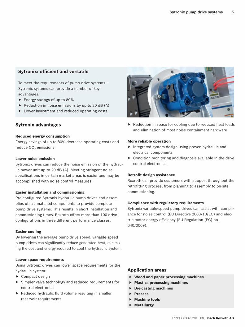
Sytronix: efficient and versatile
To meet the requirements of pump drive systems – Sytronix systems can provide a number of key advantages:
f Energy savings of up to 80% f Reduction in noise emissions by up to 20 dB (A) f Lower investment and reduced operating costs
6
Bosch Rexroth AG, R999000332, 2015-08
Sytronix pump drive systems | Sytronix system overview
Sytronix system overview
Scalable power and functionality
Sytronix variable-speed pump drives offer a comprehensive range of pumps, controllers, motors and software to suit a wide spectrum of applications. Rexroth provides machine manufacturers support during project planning, utilizing simulation models for system design and component selec-tion. Scalability of performance and function allows for an optimal choice of system components.
When using a cascade system, multiple Sytronix drives can work together to efficiently generate the flow rate required for the process.
Sytronix systems are available as pre-configured systems or as individually configured components.
Always the right Sytronix system
Rexroth offers variable-speed pump drives in three perfor-mance classes:
Basic DynamicsSytronix FcP – frequency-controlled pump drive FcP systems are suitable for standard applications with constant pressure control, for open hydraulic systems up to 90 kW. Typical applications are machine tool systems, as well as auxiliary axis movements in different applications such as presses.
High DynamicsSytronix SvP – servo-variable pump driveSvP systems use the high dynamics of servo motors (a.o. synchronous permanent magnet motors) motors to achieve significant energy savings. Capabilities include axis control functions in both open and closed hydraulic circuits requir-ing high dynamic performance, as well as advanced electrical and electrohydraulic control. Plastics processing machines and presses are key sectors for this technology.
High Power and DynamicsSytronix DFE – variable-speed pressure and flow control electronicallyDFE systems are suited for high performance applications requiring a favorable price-performance ratio. These sys-tems utilize variable displacement piston pumps and are especially suited for retrofit installations in existing systems. Capable of axis control functions, these drives offer high performance in open hydraulic circuits, and can be used in machines with multiple hydraulic functions.
7
R999000332, 2015-08, Bosch Rexroth AG
Sytronix system overview | Sytronix pump drive systems
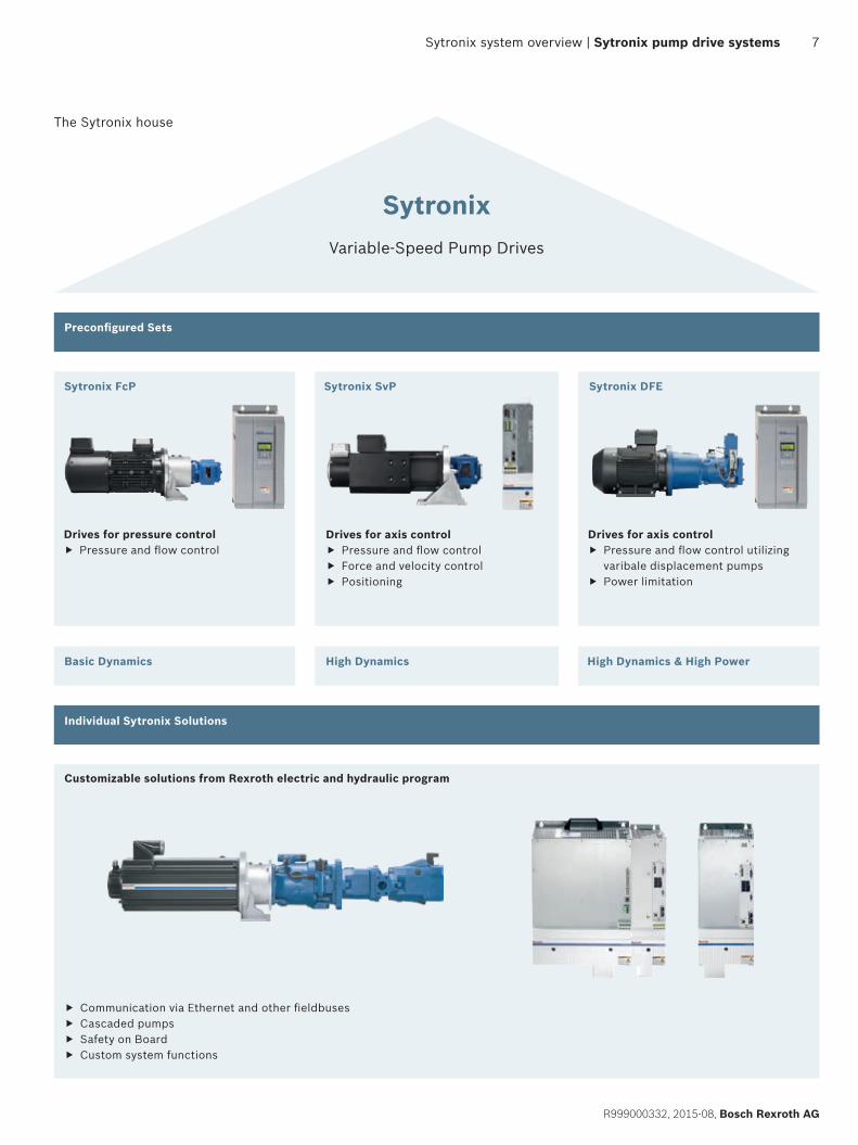
The Sytronix house
Drives for pressure control f Pressure and flow control
Drives for axis control f Pressure and flow control f Force and velocity control f Positioning
Drives for axis control f Pressure and flow control utilizing varibale displacement pumps
f Power limitation
Individual Sytronix Solutions
Basic Dynamics High Dynamics High Dynamics & High Power
Sytronix FcP
Drives for pressure control • Pressure and flow control
Customizable solutions from Rexrothelectric and hydraulic program
Sytronix SvP
Drives for axis control • Pressure and flow control
Force and velocity control• Positioning•
Sytronix DFE
Drives for axis control • Pressure and flow control utilizing
variable displacment pumps• Power limitation
SytronixVariable-Speed Pump Drives
Preconfigured sets
• Communication via Ethernet and other fieldbuses• Master/Slave operation• Cascaded pumps• Safety on Board• Custom system functions
Sytronix FcP
Customizable solutions from Rexroth electric and hydraulic program
f Communication via Ethernet and other fieldbuses f Cascaded pumps f Safety on Board f Custom system functions
Sytronix SvP Sytronix DFE
Preconfigured Sets
Individual Sytronix Solutions
Basic Dynamics High Dynamics High Dynamics & High Power
SytronixVariable-Speed Pump Drives
8
Bosch Rexroth AG, R999000332, 2015-08
Sytronix pump drive systems | Sytronix selection guide
Sytronix selection guide
The Sytronix selection guide shows the Rexroth Sytronix product family.
Variable pressure system for axis control f For closed hydraulic circuits, Sytronix SvP speed-variable
drives offer high dynamics and comprehensive electrical and electrohydraulic control options. In open hydraulic circuits, the Sytronix DFE system, utilizing electronic pump control of pressure/flow (p/Q), is an alternative option. DFE-based hydraulic drives offer an addition to the performance portfolio and are suitable for machines with multiple hydraulic using additional valves.
f In cascaded systems, multiple Sytronix drives work together to efficiently generate the flow rate required for the process.
Constant pressure systems f For constant pressure systems, cost-effective Sytronix
FcP drives using VFD driven asynchronous motors are suitable for conventional drives up to 90 kW.
Two options for Sytronix systems
After choosing the appropriate product family using the selection guide, there are two options for the pump system to fit the requirements:
f Pre-configured system sets from the product families of FcP, SvP or DFE using the selection guides (see next page).
f Assembly of individual systems by combining modules and components using application guidelines and system requirements. This can be done in collaboration with Rexroth applications specialists, for example for Sytronix systems with pump types that are not yet available in the sets (see ”Sytronix individual solutions” on page 47).
Criteria for exclusion of Sytronix systems f System pressure higher than 400 bar f Power supply higher than 500 V
On request f Hydraulic liquid other than HLP f Electrical power higher than 315 kW f Ungrounded grid f Explosion protected components f Country specific regulations f Marine certified components
Closed hydraulic circuit
DFE 5010 / 7010
SvP 50101)
30 kW 80 kW
Constant pressure system
FcP 5010 / 7010
SvP 7010
90 kW 315* kW
Maximum power
Variable pressure system for axis control
Open hydraulic circuit
One hydraulic circuit
One/multiple hydraulic circuit(s)
Requirements
*Higher power range on request 1)SvP 5010 systems have been designed for the Asian market only
9
R999000332, 2015-08, Bosch Rexroth AG
Sytronix system key | Sytronix pump drive systems
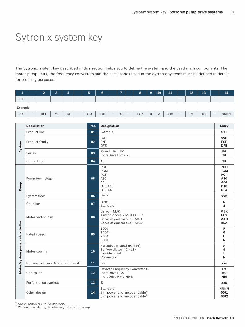
Sytronix system key
The Sytronix system key described in this section helps you to define the system and the used main components. The motor pump units, the frequency converters and the accessories used in the Sytronix systems must be defined in details for ordering purpuses.
1) Option possible only for SvP 5010 2) Without considering the efficiency ratio of the pump
Description Pos. Designation Entry
Syst
em
Product line 01 Sytronix SYT
Product family 02SvPFcPDFE
SVPFCPDFE
Series 03 Rexroth Fv = 50IndraDrive Hxx = 70
5070
Generation 04 10 10
Pum
p
Pump technology 05
PGHPGMPGFA10A4DFE-A10DFE-A4
PGHPGMPGFA10A04D10D04
System flow 06 l/min xxx
Coupling 07 DirectStandard
DS
Mot
or/s
yste
m p
ress
ure/
cont
rolle
r
Motor technology 08
Servo = MSKAsynchronous = MOT-FC IE2Servo asynchronous = MADServo asynchronous = MAS1)
MSKFC2MADREA
Rated speed 09
150017501)
20003000
FGHN
Motor cooling 10
Forced-ventilated (IC 416)Self-ventilated (IC 411)Liquid-cooledConvection
ASLN
Nominal pressure Motor-pump-unit2) 11 bar xxx
Controller 12Rexroth Frequency Converter FvIndraDrive HCSIndraDrive HMV/HMS
FVHCHM
Performance overload 13 % xxx
Other design 14Standard3 m power and encoder cable1)
5 m power and encoder cable1)
NNNN00010002
1 2 3 4 5 6 7 8 9 10 11 12 13 14
SYT – – – – – –
Example
SYT – DFE 50 10 – D10 xxx – S – FC2 N A xxx – FV xxx – NNNN
10
Bosch Rexroth AG, R999000332, 2015-08
Sytronix pump drive systems | Sytronix selection guide
Step 3The performance of your pump system is determined by the peak load that can be obtained in intermittent operation, without damage to the pump drive system. It is defined as ppeak/peff and described as the factor K in %.The individual pump-motor combinations determine the characteristic curves for the appropriate Sytronix system.
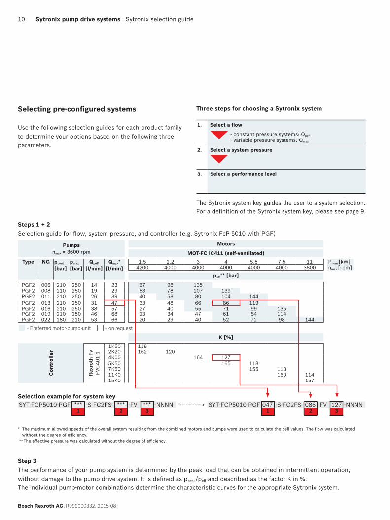
Selecting pre-configured systems
Use the following selection guides for each product family to determine your options based on the following three parameters.
Three steps for choosing a Sytronix system
1. Select a flow
- constant pressure systems: Qpeff
- variable pressure systems: Qmax
2. Select a system pressure
3. Select a performance level
The Sytronix system key guides the user to a system selection. For a definition of the Sytronix system key, please see page 9.
Steps 1 + 2Selection guide for flow, system pressure, and controller (e.g. Sytronix FcP 5010 with PGF)
Pumps nmax = 3600 rpm
Motors
MOT-FC IC411 (self-ventilated)Type NG pcont
[bar]pmax
[bar]Qpeff
[l/min]Qmax*
[l/min]1.5 2.2 3 4 5.5 7.5 11 Pnom [kW]
4200 4000 4000 4000 4000 4000 3800 nmax [rpm]peff** [bar]
PGF2 006 210 250 14 23 67 98 135PGF2 008 210 250 19 29 53 78 107 139PGF2 011 210 250 26 39 40 58 80 104 144PGF2 013 210 250 31 47 33 48 66 86 119PGF2 016 210 250 38 57 27 40 55 71 99 135PGF2 019 210 250 46 68 23 34 47 61 84 114PGF2 022 180 210 53 66 20 29 40 52 72 98 144
= Preferred motor-pump-unit = on request
K [%]
Con
trol
ler
Rex
roth
Fv
FVC
A01.
1
1K50 1182K20 162 1204K00 164 1275K50 165 1187K50 155 11311K0 160 11415K0 157
Selection example for system keySYT-FCP5010-PGF *** -S-FC2FS *** -FV *** -NNNN -------------> SYT-FCP5010-PGF 047 -S-FC2FS 086 -FV 127 -NNNN
1 2 3 1 2 3
* The maximum allowed speeds of the overall system resulting from the combined motors and pumps were used to calculate the cell values. The flow was calculated without the degree of efficiency.
** The effective pressure was calculated without the degree of efficiency.
11
R999000332, 2015-08, Bosch Rexroth AG
Sytronix selection guide | Sytronix pump drive systems
Sytronix selection guides for individually configured system components
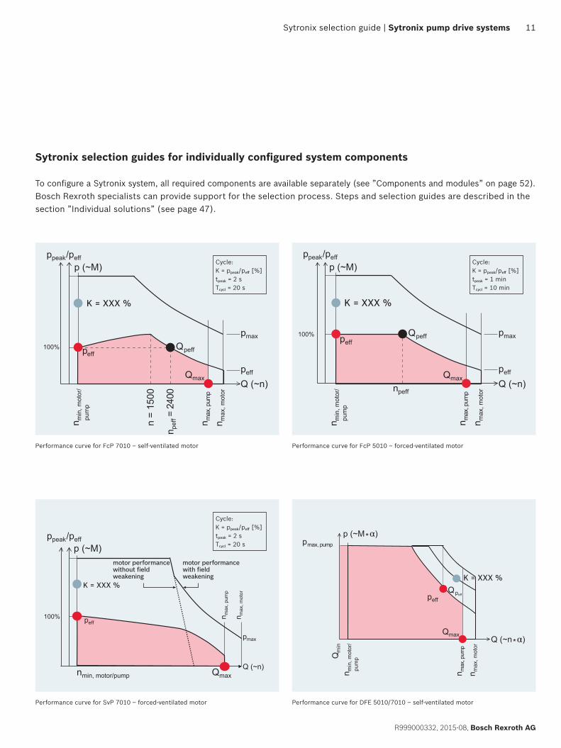
To configure a Sytronix system, all required components are available separately (see ”Components and modules” on page 52). Bosch Rexroth specialists can provide support for the selection process. Steps and selection guides are described in the section ”Individual solutions” (see page 47).
Performance curve for FcP 7010 – self-ventilated motor
Qmax
peff
n max
, pum
p
n max
, mot
or
n min
, mot
or/
pum
p
p
Q (~n)
max
peff
100%
ppeak/peffp (~M)
Qpeff
= 24
00
n =
1500
n pef
f
Cycle:K = ppeak/peff [%]tpeak = 2 sTcycl = 20 s
Performance curve for SvP 7010 – forced-ventilated motor
motor performancewith fieldweakening
n max
, pum
p
n max
, mot
or
pmax
Q (~n)
peff
motor performance without fieldweakening
100%
Qmaxnmin, motor/pump
ppeak/peffp (~M)
Cycle:K = ppeak/peff [%]tpeak = 2 sTcycl = 20 s
Performance curve for FcP 5010 – forced-ventilated motor
Qmax
peff
n max
, pum
p
n max
, mot
or
n min
mot
or/
, pu
mp
pmax
peff
Qpeff
Q (~n)
100%
ppeak/peff
p (~M)
npeff
Cycle:K = ppeak/peff [%]tpeak = 1 minTcycl = 10 min
Performance curve for DFE 5010/7010 – self-ventilated motor
Qmax
n max
, pum
p
pmax, pump
n max
, mot
or
n min
, mot
or/
pum
pQm
in
Q (~n*α)
peffQpeff
p (~M*α)
12
Bosch Rexroth AG, R999000332, 2015-08
Sytronix pump drive systems | Sytronix selection guide
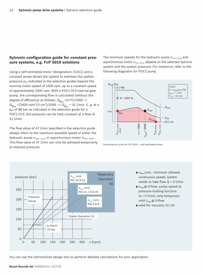
Sytronix configuration guide for constant pres-sure systems, e.g. FcP 5010 solutions
Using a self-ventilated motor (designation: IC411) and a constant pump allows the system to maintain the system pressure peff indicated in the selection guides beyond the nominal motor speed of 1500 rpm, up to a constant speed of approximately 2400 rpm. With a PGF2 013 internal gear pump, the corresponding flow is calculated (without the degree of efficiency) as follows: Qpeff
=(n*V)/1000 --> Qpeff
=(2400 rpm*13 cm3)/1000 --> Qpeff = 31 l/min. E. g. at a
peff of 86 bar as indicated in the selection guide for a PGF2 013, this pressure can be held constant at a flow of 31 l/min.
The flow value of 47 l/min specified in the selection guide always refers to the maximum possible speed of either the hydraulic pump nmax, pump or asynchronous motor nmax, motor. This flow value of 47 l/min can only be achieved temporarily at reduced pressure.
The minimum speeds for the hydraulic pump nmin, pump and asynchronous motor nmin, motor depend on the selected Sytronix system and the system pressure. For instancce, refer to the following diagramm for PGF2 pump.
You can use the SytronixSize design tool to perform detailed calculations for your application.
0 50 100 150 200 250 300 n [rpm]
250
200
150
100
50
0
pressure [bar]TemporaryOperation
S6
p_therm70 bar
PressureDecay
Stable Operation S1
nmin cont.NG 19 & 22
nmin cont.NG 11, 13 & 16
nmin cont. NG 6 & 8
∎ nmin cont.: minimum allowed continuous speed, system needs to take flow Q > 0 l/min
∎ nmin @ 0-flow: pump speed at pressure holding function Q = 0 l/min, only temporary until tmax @ 0-flow
∎ valid for viscosity 32 cSt
Performance curve for FcP 5010 – self-ventilated motor
Qmax
Qpeffpeff
n max
, pum
p
n max
, mot
or
= 24
00
n =
1500
n min
, mot
or/
pum
p
n pef
f
p
Q (~n)
max
peff
100%
ppeak/peffp (~M) Cycle:
K = ppeak/peff [%]tpeak = 1 minTcycl = 10 min
Sytronix FcP frequency-controlled pump drives | Sytronix pump drive systems 13
R999000332, 2015-08, Bosch Rexroth AG
Sytronix FcP frequency-controlled pump drives
FcP system setsSytronix FcP (frequency-controlled pump drive) systems consist of a motor-pump-unit with a standard asynchronous motor and a VFD with control electronics. With regard to dynamics, accuracy and functionality, the FcP product family covers standard performance hydraulic drives and is suitable in the following applications:
f Constant pressure systems up to 90 kW f Applications with controlled volume flow profile or
where alternating p/Q control is required f Open hydraulic circuits f 1-quadrant operation
Starting with the basic FcP system, a PGF family internal gear pump is used for pressure and flow control. For higher pressure and performance, the PGH internal gear pump is utilized, as well as A10 and A4 axial piston variable displace-ment pumps. When used at high pressures, utilizing variable displacement piston pumps helps to reduce the torque on the electric motor so that a smaller drive can be selected.
FcP 5010 and FcP 7010 utilize different VFD drive electronics. IndraDrive controller and Rexroth Fv VFD. Differences between both types include the type and scope of communication and bus interfaces, as well as additional functionality and user interfaces.
Components f Hydraulic pump f Electric motor f VFD with control electronics f Pressure transducer
ApplicationsThe FcP systems are energy-efficient variable-speed pump drives for constant pressure systems (e.g. machine tools) with open hydraulic circuits as well as in systems for pres-sure supply for auxiliary axis movements, such as in presses and metallurgy.
PLC
Controller
AC Supply
n
3∼
3
p/F
pACTPCMD
pU
14 Sytronix pump drive systems | Sytronix FcP frequency-controlled pump drives
Bosch Rexroth AG, R999000332, 2015-08
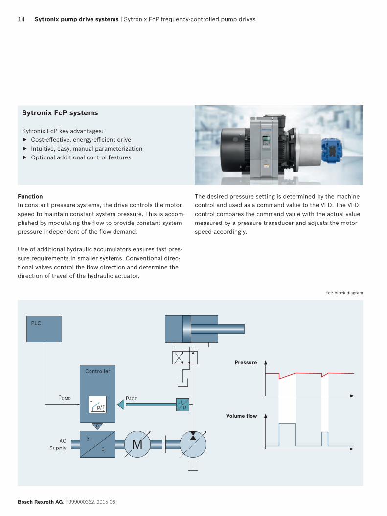
Sytronix FcP systems
Sytronix FcP key advantages: f Cost-effective, energy-efficient drive f Intuitive, easy, manual parameterization f Optional additional control features
FunctionIn constant pressure systems, the drive controls the motor speed to maintain constant system pressure. This is accom-plished by modulating the flow to provide constant system pressure independent of the flow demand.
Use of additional hydraulic accumulators ensures fast pres-sure requirements in smaller systems. Conventional direc-tional valves control the flow direction and determine the direction of travel of the hydraulic actuator.
The desired pressure setting is determined by the machine control and used as a command value to the VFD. The VFD control compares the command value with the actual value measured by a pressure transducer and adjusts the motor speed accordingly.
FcP block diagram
Pressure
Volume flow
FcP 7010 | Sytronix FcP frequency-controlled pump drives | Sytronix pump drive systems 15
R999000332, 2015-08, Bosch Rexroth AG
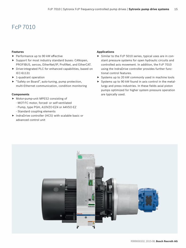
FcP 7010
Features f Performance up to 90 kW effective f Support for most industry standard buses: CANopen,
PROFIBUS, sercos, EtherNet/IP, ProfiNet, and EtherCAT. f Drive-integrated PLC for enhanced capabilities, based on
IEC-61131 f 1-quadrant operation f ”Safety on Board”, auto-tuning, pump protection,
multi-Ethernet communication, condition monitoring
Components f Motor-pump-unit MPES2 consisting of
- MOT-FC motor, forced- or self-ventilated - Pump, type PGH, A10VZO-EZ4 or A4VSO-EZ - Standard coupling elements
f IndraDrive controller (HCS) with scalable basic or advanced control unit
Applications f Similar to the FcP 5010 series, typical uses are in con-
stant pressure systems for open hydraulic circuits and controlled axis movement. In addition, the FcP 7010 using the IndraDrive controller provides further func-tional control features.
f Systems up to 20 kW commonly used in machine tools f Systems up to 90 kW found in axis control in the metal-
lurgy and press industries. In these fields axial piston pumps optimized for higher system pressure operation are typically used.
16 Sytronix pump drive systems | Sytronix FcP frequency-controlled pump drives | FcP 7010
Bosch Rexroth AG, R999000332, 2015-08
FcP 7010 with PGH, MOT-FC self-ventilated
Selection guide for Sytronix FcP 7010 with PGH
Pumps1)
nmax = 3000 rpm
Motors1)
MOT-FC IC411 (self-ventilated)
Type NG pcont
[bar]pmax
[bar]Qpeff
[l/min]Qmax
[l/min]1.5 2.2 3 4 5.5 7.5 11 15 18.5 22 30 37 45 55 75 90 Pnom [kW]
4200 4000 4000 4000 4000 4000 3800 3800 3800 3800 3800 2800 2800 2800 2800 2800 nmax [rpm]peff** [bar]
PGH2005 315 350 12 15 87 128 176 229006 315 350 14 18 73 106 147 191 264008 315 350 19 24 54 80 110 143 198 269
PGH3011 315 350 26 33 58 80 104 144 196 288013 315 350 31 39 49 68 88 122 166 244016 315 350 38 48 40 55 71 99 135 198 269
PGH4
020 315 350 48 60 22 32 44 57 79 108 158 216 264 314025 315 350 60 75 17 26 35 46 63 86 127 172 211 252032 315 350 77 96 20 27 36 49 67 99 135 165 197 267040 315 350 96 120/112* 16 22 29 40 54 79 108 132 157 213 262050 250 310 120 150/140* 18 23 32 43 63 86 106 126 171 209
PGH5
063 315 350 151 189/176* 18 25 34 50 68 84 100 135 166 202 247080 315 350 192 240/224* 20 27 40 54 66 79 107 131 159 195 266100 315 350 240 300/280* 16 22 32 43 53 63 85 105 128 156 212 255125 315 350 300 375/350* 17 25 34 42 50 68 84 102 125 170 204160 210 260 384 480/448* 20 27 33 39 53 65 80 97 133 159200 170 210 480 600/560* 16 22 26 31 43 52 64 78 106 128250 135 170 600 750/700* 17 21 25 34 42 51 62 85 102
* Flow limited by the maximum motor speed ** The effective pressure was calculated without the degree of efficiency.
K [%]
Con
trol
ler
Rex
roth
Indr
aDri
ve C HCS01.1E
-W0008 79-W0018 224 165 125-W0028 189 146 105-W0054 191 140 100
HCS02.1E -W0070 187 133 100
HCS03.1E
-W0070 161 132 113-W0100 183 135 109-W0150 176 142 117-W0210 179 146 112
HCS04.2E -W0350 189 158-W0420 192
1) The pump and motor can also be ordered separately as motor-pump-unit MPES2 (see ”Motor-pump-units” starting on page 53) Note: For a detailed explanation of the tables, see page 10
Selection example for system keySYT-FCP7010-PGH *** -S-FC2FS *** -HC *** -NNNN ---------> SYT-FCP7010-PGH 075 -S-FC2FS 127 -HC 100 -NNNN
1 2 3 1 2 3
= Preferred motor- pump-unit
= on request
Performance curve for FcP 7010 – self-ventilated motor
Qmax
peff
n max
, pum
p
n max
, mot
or
n min
, mot
or/
pum
p
p
Q (~n)
max
peff
100%
ppeak/peffp (~M)
Qpeff
= 24
00
n =
1500
n pef
f
Cycle:K = ppeak/peff [%]tpeak = 2 sTcycl = 20 s
Detailed component information:Motors: see ”Motors” starting on page 66Pumps: data sheets 10227, 10223Controller: catalog R999000018 (DE), R999000019 (EN)
FcP 7010 | Sytronix FcP frequency-controlled pump drives | Sytronix pump drive systems 17
R999000332, 2015-08, Bosch Rexroth AG
FcP 7010 with PGH, MOT-FC forced-ventilated
Selection guide for Sytronix FcP 7010 with PGH
Pumps1)
nmax = 3000 rpm
Motors1)
MOT-FC IC416 (forced-ventilated)
Type NG pcont
[bar]pmax
[bar]Qpeff
[l/min]Qmax
[l/min]1.5 2.2 3 4 5.5 7.5 11 15 18.5 22 30 37 45 55 75 90 Pnom [kW]
4200 4000 4000 4000 4000 4000 3800 3800 3800 3800 3800 2800 2800 2800 2800 2800 nmax [rpm]peff** [bar]
PGH2005 315 350 8 15 124 182 251006 315 350 9 18 104 152 209 272008 315 350 12 24 78 114 157 204 283
PGH3011 315 350 17 33 83 114 149 206 280013 315 350 20 39 70 97 126 174 237016 315 350 24 48 57 79 102 141 192 283
PGH4
020 315 350 30 60 31 46 63 82 113 154 226 308025 315 350 38 75 25 36 50 65 90 123 181 246 302032 315 350 48 96 19 28 39 51 71 96 141 192 236 281040 315 350 60 120 16 23 31 41 57 77 113 154 188 225 305050 250 310 75 150 18 25 33 45 62 90 123 151 180 244
PGH5
063 315 350 95 189/176* 20 26 36 49 72 98 120 143 193 237 289080 315 350 120 240/224* 16 20 28 38 57 77 94 112 152 187 228 278100 315 350 150 300/280* 16 23 31 45 62 75 90 122 150 182 222 303125 315 350 188 375/350* 18 25 36 49 60 72 98 120 146 178 243 292160 210 260 240 480/448* 19 28 38 47 56 76 93 114 139 190200 170 210 300 600/560* 15 23 31 38 45 61 75 91 111 152250 135 170 375 750/700* 18 25 30 36 49 60 73 89 121
* Flow limited by the maximum motor speed ** The effective pressure was calculated without the degree of efficiency.
K [%]
Con
trol
ler
Rex
roth
Indr
aDri
ve C HCS01.1E
-W0008 79-W0018 224 165 125-W0028 189 146 105-W0054 191 140 100
HCS02.1E -W0070 187 133 100
HCS03.1E
-W0070 161 132 113-W0100 183 135 109-W0150 176 142 117-W0210 179 146 112
HCS04.2E -W0350 189 158-W0420 192
1) The pump and motor can also be ordered separately as motor-pump-unit MPES2 (see ”Motor-pump-units” starting on page 53) Note: For a detailed explanation of the tables, see page 10
Selection example for system keySYT-FCP7010-PGH *** -S-FC2FA *** -HC *** -NNNN ---------> SYT-FCP7010-PGH 075 -S-FC2FA 181 -HC 100 -NNNN
1 2 3 1 2 3
= Preferred motor- pump-unit
= on request
Detailed component information:Motors: see ”Motors” starting on page 66Pumps: data sheets 10227, 10223Controller: catalog R999000018 (DE), R999000019 (EN)
Performance curve for FcP 7010 – forced-ventilated motor
Qmax
peff
n max
, pum
p
n max
, mot
or
n min
mot
or/
, pu
mp
pmax
peff
Qpeff
Q (~n)
100%
ppeak/peff
p (~M)
npeff
Cycle:K = ppeak/peff [%]tpeak = 2 sTcycl = 20 s
18 Sytronix pump drive systems | Sytronix FcP frequency-controlled pump drives | FcP 7010
Bosch Rexroth AG, R999000332, 2015-08
FcP 7010 with A10VZO-EZ4
n max
, pum
p
n max
, mot
or
n min
, mot
or/
pum
p
pmax
peff
Q (~n)
ppeak/peff
100%
p (~M)Cycle: K = ppeak/peff [%]tpeak = 2 sTcycl = 20 s
Detailed component information:Motors: see ”Motors” starting on page 66Pumps: data sheet 91485Controller: catalog R999000241 (DE), R999000242 (EN)
Performance curve for FcP 7010 – self-ventilated motor with axial piston pump with two-point displacement
Selection guide for Sytronix FcP 7010 with A10VZO-EZ4
Pumps1) Motors1)
MOT-FC IC411 (self-ventilated)Type NG pcont
[bar]pmax
[bar]nmax
[rpm]Qpeff
[l/min]Qmax
[l/min]1.5 2.2 3 4 5.5 7.5 11 15 18.5 22 30 37 45 55 75 90 Pnom [kW]
4200 4000 4000 4000 4000 4000 3800 3800 3800 3800 3800 2800 2800 2800 2800 2800 nmax [rpm]peff* [bar]
A10V
ZO-E
Z4
010 250 315 3600 24 37 59 87 120 156 215018 280 350 3300 43 59 35 51 70 91 126 171028 280 350 3000 67 84 22 33 45 58 81 110 162 220045 280 350 3000 108 135 20 28 36 50 68 101 137 168 200071 280 350 2550 170 181 18 23 32 43 64 87 106 126 171 210 256100 280 350 2300 230 230 23 31 45 62 75 90 122 150 182 222140 280 350 2200 308 308 16 22 32 44 54 64 87 107 130 159 217 260180 280 350 1800 324 324 17 25 34 42 50 68 83 101 124 169 202
* The effective pressure was calculated without the degree of efficiency
= Preferred motor-pump-unit = on request
K [%]
Con
trol
ler
Rex
roth
Indr
aDri
ve C HCS01.1E
-W0008 79-W0018 224 165 125-W0028 189 146 105-W0054 191 140 100
HCS02.1E -W0070 187 133 100
HCS03.1E
-W0070 161 132 113-W0100 183 135 109-W0150 176 142 117-W0210 179 146 112
HCS04.2E -W0350 189 158-W0420 192
1) The pump and motor can also be ordered separately as motor-pump-unit MPES2 (see ”Motor-pump-units” starting on page 53) Note: For a detailed explanation of the tables, see page 10
Selection example for system keySYT-FCP7010-A10 *** -S-FC2FS *** -HC *** -NNNN ---------> SYT-FCP7010-A10 084 -S-FC2FS 110 -HC 140 -NNNN
1 2 3 1 2 3
FcP 7010 | Sytronix FcP frequency-controlled pump drives | Sytronix pump drive systems 19
R999000332, 2015-08, Bosch Rexroth AG
n max
, pum
p
n max
, mot
or
n min
, mot
or/
pum
p
pmax
peff
Q (~n)
ppeak/peff
100%
p (~M)Cycle:K = ppeak/peff [%]tpeak = 2 sTcycl = 20 s
Detailed component information:Motors: see ”Motors” starting on page 66Pumps: data sheet 92050 (for control valve refer to data sheet 91485)Controller: catalog R999000241 (DE), R999000242 (EN)
Performance curve for FcP 7010 – self-ventilated motor with axial piston pump with two-point displacement
Selection guide for Sytronix FcP 7010 with A4VSO-EZ
Pumps1) Motors1)
MOT-FC IC411 (self-ventilated)Type NG pcont
[bar]pmax
[bar]nmax
[rpm]Qpeff
[l/min]Qmax
[l/min]18.5 22 30 37 45 55 75 90 Pnom [kW]3800 3800 3800 2800 2800 2800 2800 2800 nmax [rpm]
peff* [bar]
A4VS
O-E
Z 040 350 400 2600 96 104 188 225 305071 350 400 2200 156 156 106 127 172 211 257 313125 350 400 1800 225 225 60 72 98 120 146 178 234 292180 350 400 1800 324 324 68 83 101 124 169 202
* The effective pressure was calculated without the degree of efficiency.
= Preferred motor-pump-unit = on request
K [%]
Con
trol
ler
Rex
roth
In
draD
rive
C
HCS03.1E
-W0070 132 113-W0100 183 135 109-W0150 176 142 117-W0210 179 146 112
HCS04.2E -W0350 189 158-W0420 192
1) The pump and motor can also be ordered separately as motor-pump-unit MPES2 (see ”Motor-pump-units” starting on page 53) Note: For a detailed explanation of the tables, see page 10
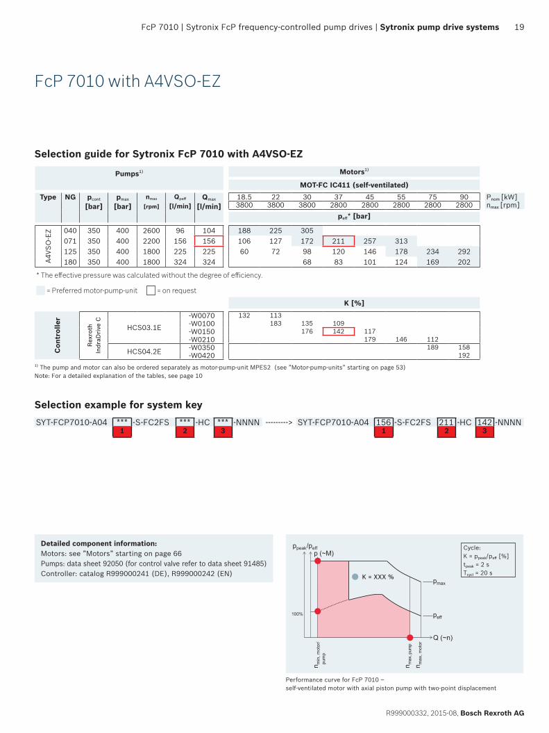
Selection example for system keySYT-FCP7010-A04 *** -S-FC2FS *** -HC *** -NNNN ---------> SYT-FCP7010-A04 156 -S-FC2FS 211 -HC 142 -NNNN
1 2 3 1 2 3
FcP 7010 with A4VSO-EZ
20 Sytronix pump drive systems | Sytronix FcP frequency-controlled pump drives | FcP 5010
Bosch Rexroth AG, R999000332, 2015-08
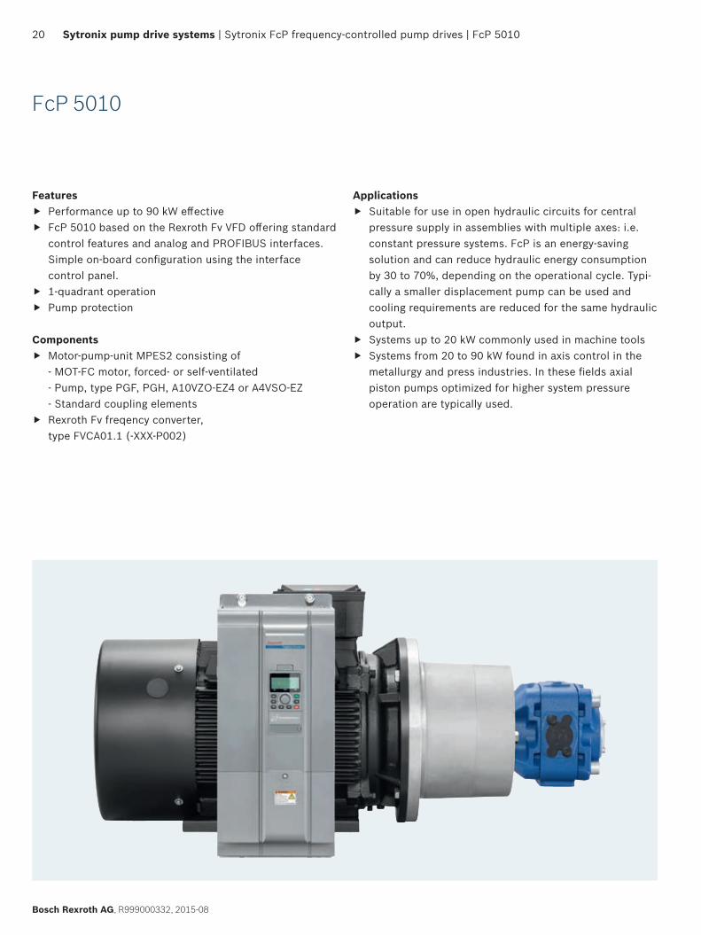
FcP 5010
Features f Performance up to 90 kW effective f FcP 5010 based on the Rexroth Fv VFD offering standard
control features and analog and PROFIBUS interfaces. Simple on-board configuration using the interface control panel.
f 1-quadrant operation f Pump protection
Components f Motor-pump-unit MPES2 consisting of
- MOT-FC motor, forced- or self-ventilated - Pump, type PGF, PGH, A10VZO-EZ4 or A4VSO-EZ - Standard coupling elements
f Rexroth Fv freqency converter, type FVCA01.1 (-XXX-P002)
Applications f Suitable for use in open hydraulic circuits for central
pressure supply in assemblies with multiple axes: i.e. constant pressure systems. FcP is an energy-saving solution and can reduce hydraulic energy consumption by 30 to 70%, depending on the operational cycle. Typi-cally a smaller displacement pump can be used and cooling requirements are reduced for the same hydraulic output.
f Systems up to 20 kW commonly used in machine tools f Systems from 20 to 90 kW found in axis control in the
metallurgy and press industries. In these fields axial piston pumps optimized for higher system pressure operation are typically used.
FcP 5010 | Sytronix FcP frequency-controlled pump drives | Sytronix pump drive systems 21
R999000332, 2015-08, Bosch Rexroth AG
Detailed component information:Motors: see ”Motors” starting on page 66Pumps: data sheet 10213Controller: catalog R912004739
Qmax
peff
n max
, pum
p
n max
, mot
or
n min
, mot
or/
pum
p
p
Q (~n)
max
peff
100%
ppeak/peffp (~M)
Qpeff
= 24
00
n =
1500
n pef
f
Performance curve for FcP 5010 – self-ventilated motor
Cycle:K = ppeak/peff [%]tpeak = 1 minTcycl = 10 min
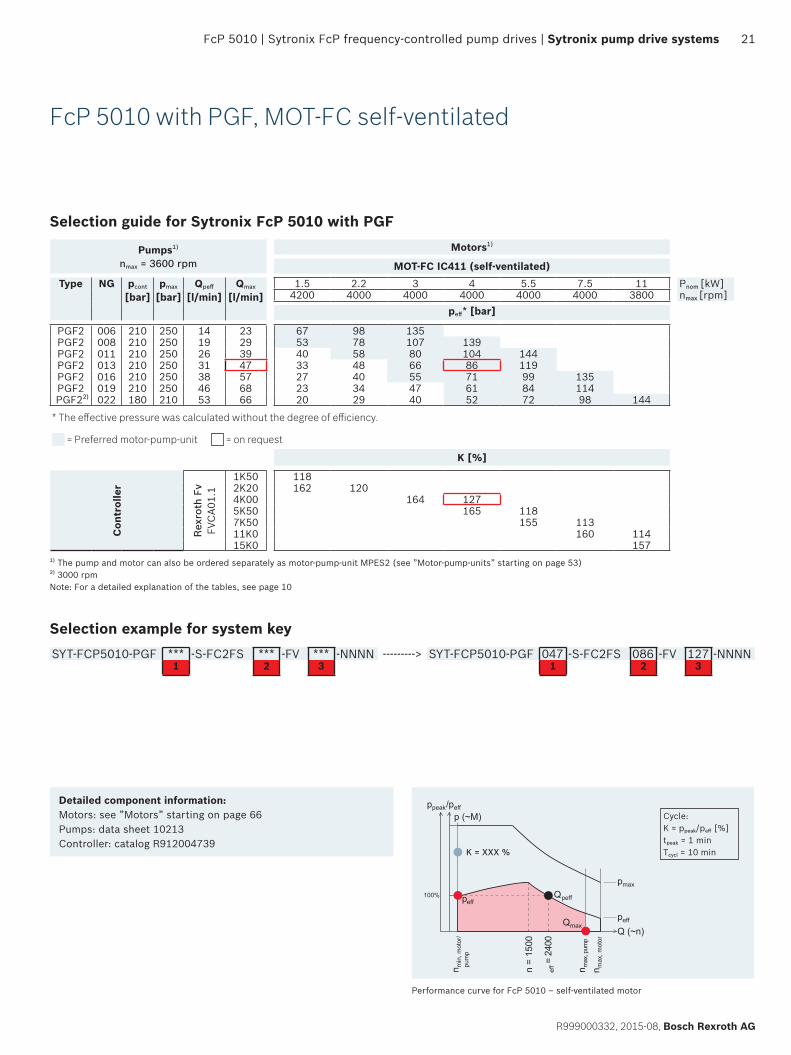
Selection guide for Sytronix FcP 5010 with PGF
Pumps1)
nmax = 3600 rpmMotors1)
MOT-FC IC411 (self-ventilated)Type NG pcont
[bar]pmax
[bar]Qpeff
[l/min]Qmax
[l/min]1.5 2.2 3 4 5.5 7.5 11 Pnom [kW]
4200 4000 4000 4000 4000 4000 3800 nmax [rpm]peff* [bar]
PGF2 006 210 250 14 23 67 98 135PGF2 008 210 250 19 29 53 78 107 139PGF2 011 210 250 26 39 40 58 80 104 144PGF2 013 210 250 31 47 33 48 66 86 119PGF2 016 210 250 38 57 27 40 55 71 99 135PGF2 019 210 250 46 68 23 34 47 61 84 114
PGF22) 022 180 210 53 66 20 29 40 52 72 98 144
* The effective pressure was calculated without the degree of efficiency.
= Preferred motor-pump-unit = on request
K [%]
Con
trol
ler
Rex
roth
Fv
FVC
A01.
1
1K50 1182K20 162 1204K00 164 1275K50 165 1187K50 155 11311K0 160 11415K0 157
1) The pump and motor can also be ordered separately as motor-pump-unit MPES2 (see ”Motor-pump-units” starting on page 53) 2) 3000 rpm Note: For a detailed explanation of the tables, see page 10
Selection example for system keySYT-FCP5010-PGF *** -S-FC2FS *** -FV *** -NNNN ---------> SYT-FCP5010-PGF 047 -S-FC2FS 086 -FV 127 -NNNN
1 2 3 1 2 3
FcP 5010 with PGF, MOT-FC self-ventilated
22 Sytronix pump drive systems | Sytronix FcP frequency-controlled pump drives | FcP 5010
Bosch Rexroth AG, R999000332, 2015-08
Detailed component information:Motors: see ”Motors” starting on page 66Pumps: data sheet 10213Controller: catalog R912004739
FcP 5010 with PGF, MOT-FC forced-ventilated
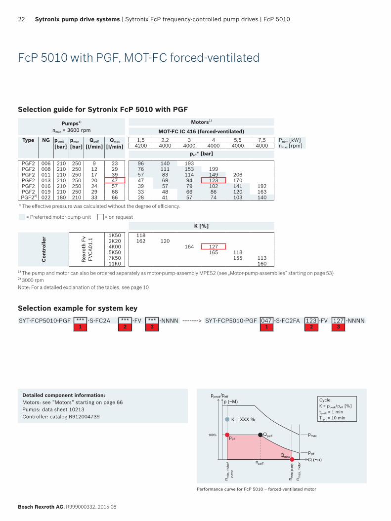
Selection guide for Sytronix FcP 5010 with PGF
Pumps1)
nmax = 3600 rpmMotors1)
MOT-FC IC 416 (forced-ventilated)Type NG pcont
[bar]pmax
[bar]Qpeff
[l/min]Qmax
[l/min]1,5 2,2 3 4 5,5 7,5 Pnom [kW]
4200 4000 4000 4000 4000 4000 nmax [rpm]peff* [bar]
PGF2 006 210 250 9 23 96 140 193PGF2 008 210 250 12 29 76 111 153 199PGF2 011 210 250 17 39 57 83 114 149 206PGF2 013 210 250 20 47 47 69 94 123 170PGF2 016 210 250 24 57 39 57 79 102 141 192PGF2 019 210 250 29 68 33 48 66 86 120 163
PGF22) 022 180 210 33 66 28 41 57 74 103 140
* The effective pressure was calculated without the degree of efficiency.
= Preferred motor-pump-unit = on request
K [%]
Con
trol
ler
Rex
roth
Fv
FVC
A01.
1
1K50 1182K20 162 1204K00 164 1275K50 165 1187K50 155 11311K0 160
1) The pump and motor can also be ordered separately as motor-pump-assembly MPES2 (see „Motor-pump-assemblies“ starting on page 53) 2) 3000 rpm Note: For a detailed explanation of the tables, see page 10
Selection example for system keySYT-FCP5010-PGF *** -S-FC2A *** -FV *** -NNNN ---------> SYT-FCP5010-PGF 047 -S-FC2FA 123 -FV 127 -NNNN
1 2 3 1 2 3
Performance curve for FcP 5010 – forced-ventilated motor
Qmax
peff
n max
, pum
p
n max
, mot
or
n min
mot
or/
, pu
mp
pmax
peff
Qpeff
Q (~n)
100%
ppeak/peff
p (~M)
npeff
Cycle:K = ppeak/peff [%]tpeak = 1 minTcycl = 10 min
FcP 5010 | Sytronix FcP frequency-controlled pump drives | Sytronix pump drive systems 23
R999000332, 2015-08, Bosch Rexroth AG
Selection guide for Sytronix FcP 5010 with PGHPumps1)
nmax = 3000 rpm
Motors1)
MOT-FC IC 411 (self-ventilated)
Type NG pcont
[bar]pmax
[bar]Qpeff
[l/min]Qmax
[l/min]1,5 2,2 3 4 5,5 7,5 11 15 18,5 22 30 37 45 55 75 90 Pnom [kW]
4200 4000 4000 4000 4000 4000 3800 3800 3800 3800 3800 2800 2800 2800 2800 2800 nmax [rpm]
peff** [bar]
PGH2005 315 350 12 15 87 128 176 229006 315 350 14 18 73 106 147 191 264008 315 350 19 24 54 80 110 143 198 269
PGH3011 315 350 26 33 58 80 104 144 196 288013 315 350 31 39 49 68 88 122 166 244016 315 350 38 48 40 55 71 99 135 198 269
PGH4
020 315 350 48 60 22 32 44 57 79 108 158 216 264 314025 315 350 60 75 17 26 35 46 63 86 127 172 211 252032 315 350 77 96 20 27 36 49 67 99 135 165 197 267040 315 350 96 120/112* 16 22 29 40 54 79 108 132 157 213 262050 250 310 120 150/140* 18 23 32 43 63 86 106 126 171 209
PGH5
063 315 350 151 189/176* 18 25 34 50 68 84 100 135 166 202 247080 315 350 192 240/224* 20 27 40 54 66 79 107 131 159 195 266100 315 350 240 300/280* 16 22 32 43 53 63 85 105 128 156 212 255125 315 350 300 375/350* 17 25 34 42 50 68 84 102 125 170 204160 210 260 384 480/448* 20 27 33 39 53 65 80 97 133 159200 170 210 480 600/560* 16 22 26 31 43 52 64 78 106 128250 135 170 600 750/700* 17 21 25 34 42 51 62 85 102
* Flow limited by the maximum motor speed ** The effective pressure was calculated without the degree of efficiency.
K [%]
Con
trol
ler
Rex
roth
Fv
FVC
A01.
1
1K50 1182K20 162 1204K00 164 1275K50 165 1187K50 155 11311K0 160 11415K0 157 11818K5 186 139 11522K0 157 129 11030K0 176 150 11137K0 188 139 11245K0 176 142 11755K0 164 136 11175K0 188 154 11790K0 185 141 117
1) The pump and motor can also be ordered separately as motor-pump-unit MPES2 (see ”Motor-pump-units” starting on page 53) Note: For a detailed explanation of the tables, see page 10
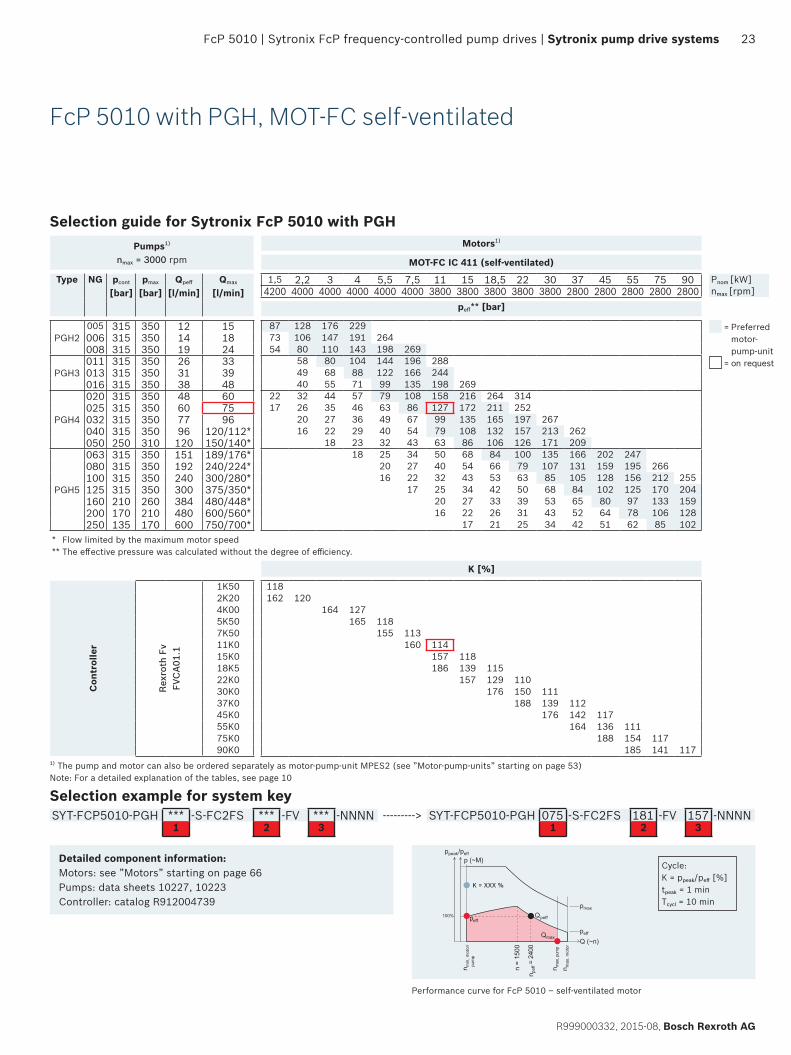
Selection example for system keySYT-FCP5010-PGH *** -S-FC2FS *** -FV *** -NNNN ---------> SYT-FCP5010-PGH 075 -S-FC2FS 181 -FV 157 -NNNN
1 2 3 1 2 3
FcP 5010 with PGH, MOT-FC self-ventilated
Performance curve for FcP 5010 – self-ventilated motor
Qmax
peff
n max
, pum
p
n max
, mot
or
n min
, mot
or/
pum
p
p
Q (~n)
max
peff
100%
ppeak/peffp (~M)
Qpeff
= 24
00
n =
1500
n pef
f
Cycle:K = ppeak/peff [%]tpeak = 1 minTcycl = 10 min
Detailed component information:Motors: see ”Motors” starting on page 66Pumps: data sheets 10227, 10223Controller: catalog R912004739
= Preferred motor- pump-unit
= on request

24 Sytronix pump drive systems | Sytronix FcP frequency-controlled pump drives | FcP 5010
Bosch Rexroth AG, R999000332, 2015-08
Selection guide for Sytronix FcP 5010 with PGHPumps1)
nmax = 3000 rpm
Motors1)
MOT-FC IC 411 (forced-ventilated)
Type NG pcont
[bar]pmax
[bar]Qpeff
[l/min]Qmax
[l/min]1,5 2,2 3 4 5,5 7,5 11 15 18,5 22 30 37 45 55 75 90 Pnom [kW]
4200 4000 4000 4000 4000 4000 3800 3800 3800 3800 3800 2800 2800 2800 2800 2800 nmax [rpm]
peff** [bar]
PGH2005 315 350 8 15 124 182 251006 315 350 9 18 104 152 209 272008 315 350 12 24 78 114 157 204 283
PGH3011 315 350 17 33 83 114 149 206 280013 315 350 20 39 70 97 126 174 237016 315 350 24 48 57 79 102 141 192 283
PGH4
020 315 350 30 60 31 46 63 82 113 154 226 308025 315 350 38 75 25 36 50 65 90 123 181 246 302032 315 350 48 96 19 28 39 51 71 96 141 192 236 281040 315 350 60 120 16 23 31 41 57 77 113 154 188 225 305050 250 310 75 150 18 25 33 45 62 90 123 151 180 244
PGH5
063 315 350 95 189/176* 20 26 36 49 72 98 120 143 193 237 289080 315 350 120 240/224* 16 20 28 38 57 77 94 112 152 187 228 278100 315 350 150 300/280* 16 23 31 45 62 75 90 122 150 182 222 303125 315 350 188 375/350* 18 25 36 49 60 72 98 120 146 178 243 292160 210 260 240 480/448* 19 28 38 47 56 76 93 114 139 190200 170 210 300 600/560* 15 23 31 38 45 61 75 91 111 152250 135 170 375 750/700* 18 25 30 36 49 60 73 89 121
* Flow limited by the maximum motor speed ** The effective pressure was calculated without the degree of efficiency.
K [%]
Con
trol
ler
Rex
roth
Fv
FVC
A01.
1
1K50 1182K20 162 1204K00 164 1275K50 165 1187K50 155 11311K0 160 11415K0 157 11818K5 186 139 11522K0 157 129 11030K0 176 150 11137K0 188 139 11245K0 176 142 11755K0 164 136 11175K0 188 154 11790K0 185 141 117
1) The pump and motor can also be ordered separately as motor-pump-unit MPES2 (see ”Motor-pump-units” starting on page 53) Note: For a detailed explanation of the tables, see page 10
Selection example for system keySYT-FCP5010-PGH *** -S-FC2FA *** -FV *** -NNNN ---------> SYT-FCP5010-PGH 075 -S-FC2FA 181 -FV 157 -NNNN
1 2 3 1 2 3
FcP 5010 with PGH, MOT-FC forced-ventilated
Performance curve for FcP 5010 – forced-ventilated motor
Qmax
peff
n max
, pum
p
n max
, mot
or
n min
mot
or/
, pu
mp
pmax
peff
Qpeff
Q (~n)
100%
ppeak/peff
p (~M)
npeff
Cycle:K = ppeak/peff [%]tpeak = 1 minTcycl = 10 min
Detailed component information:Motors: see ”Motors” starting on page 66Pumps: data sheets 10227, 10223Controller: catalog R912004739
= Preferred motor- pump-unit
= on request
FcP 5010 | Sytronix FcP frequency-controlled pump drives | Sytronix pump drive systems 25
R999000332, 2015-08, Bosch Rexroth AG
n max
, pum
p
n max
, mot
or
n min
, mot
or/
pum
p
pmax
peff
Q (~n)
ppeak/peff
100%
p (~M)Cycle:K = ppeak/peff [%]tpeak = 1 minTcycl = 10 min
Detailed component information:Motors: see ”Motors” starting on page 66Pumps: data sheet 91485Controller: catalog R912004739
Performance curve for FcP 5010 – self-ventilated motor with axial piston pump with two-point displacement
Selection guide for Sytronix FcP 5010 with A10VZO-EZ4
Pumps1) Motors1)
MOT-FC IC411 (self-ventilated)Type NG pcont
[bar]pmax
[bar]nmax
[rpm]Qpeff
[l/min]Qmax
[l/min]1.5 2.2 3 4 5.5 7.5 11 15 18.5 22 30 37 45 55 75 90 Pnom [kW]
4200 4000 4000 4000 4000 4000 3800 3800 3800 3800 3800 2800 2800 2800 2800 2800 nmax [rpm]
peff* [bar]
A10V
ZO-E
Z4
010 250 315 3600 24 37 59 87 120 156 215018 280 350 3300 43 59 35 51 70 91 126 171028 280 350 3000 67 84 22 33 45 58 81 110 162 220045 280 350 3000 108 135 20 28 36 50 68 101 137 168 200071 280 350 2550 170 181 18 23 32 43 64 87 106 126 171 210 256100 280 350 2300 230 230 23 31 45 62 75 90 122 150 182 222140 280 350 2200 308 308 16 22 32 44 54 64 87 107 130 159 217 260180 280 350 1800 324 324 17 25 34 42 50 68 83 101 124 169 202
* The effective pressure was calculated without the degree of efficiency.
= Preferred motor-pump-unit = on request
K [%]
Con
trol
ler
Rex
roth
Fv
FVC
A01.
1
1K50 1182K20 162 1204K00 164 1275K50 165 1187K50 155 11311K0 160 11415K0 157 11818K5 186 139 11522K0 157 129 11030K0 176 150 11137K0 188 139 11245K0 176 142 11755K0 164 136 11175K0 188 154 11790K0 185 141 117
1) The pump and motor can also be ordered separately as motor-pump-unit MPES2 (see ”Motor-pump-units” starting on page 53) Note: For a detailed explanation of the tables, see page 10
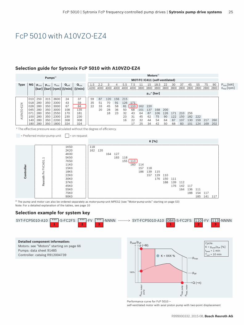
Selection example for system keySYT-FCP5010-A10 *** -S-FC2FS *** -FV *** -NNNN ---------> SYT-FCP5010-A10 084 -S-FC2FS 110 -FV 113 -NNNN
1 2 3 1 2 3
FcP 5010 with A10VZO-EZ4
26 Sytronix pump drive systems | Sytronix FcP frequency-controlled pump drives | FcP 5010
Bosch Rexroth AG, R999000332, 2015-08
Qmax
n max
, pum
p
n max
, mot
or
n min
, mot
or/
pum
p
pmax
peff
Q (~n)
ppeak/peff
100%
p (~M)Cycle:K = ppeak/peff [%]tpeak = 1 minTcycl = 10 min
Detailed component information:Motors: see ”Motors” starting on page 66Pumps: data sheet 92050 (for control valve refer to data sheet 91485)Controller: catalog R912004739
Performance curve for FcP 5010 – self-ventilated motor with axial piston pump with two-point displacement
Selection guide for Sytronix FcP 5010 with A4VSO-EZ
Pumps1) Motors1)
MOT-FC IC411 (self-ventilated)Type NG pcont
[bar]pmax
[bar]nmax
[rpm]Qpeff
[l/min]Qmax
[l/min]18.5 22 30 37 45 55 75 90 Pnom [kW]3800 3800 3800 2800 2800 2800 2800 2800 nmax [rpm]
peff* [bar]
A4VS
O-
EZ
040 350 400 2600 96 104 188 225 305071 350 400 2200 156 156 106 127 172 211 257 313125 350 400 1800 225 225 60 72 98 120 146 178 234 292180 350 400 1800 324 324 68 83 101 124 169 202
* The effective pressure was calculated without the degree of efficiency.
= Preferred motor-pump-unit = on request
K [%]
Con
trol
ler
Rex
roth
Fv
FVC
A01.
1
18K5 11522K0 129 11030K0 176 150 11137K0 188 139 11245K0 176 142 11755K0 164 136 11175K0 188 154 11790K0 185 141 117
1) The pump and motor can also be ordered separately as motor-pump-unit MPES2 (see ”Motor-pump-units” starting on page 53) Note: For a detailed explanation of the tables, see page 10
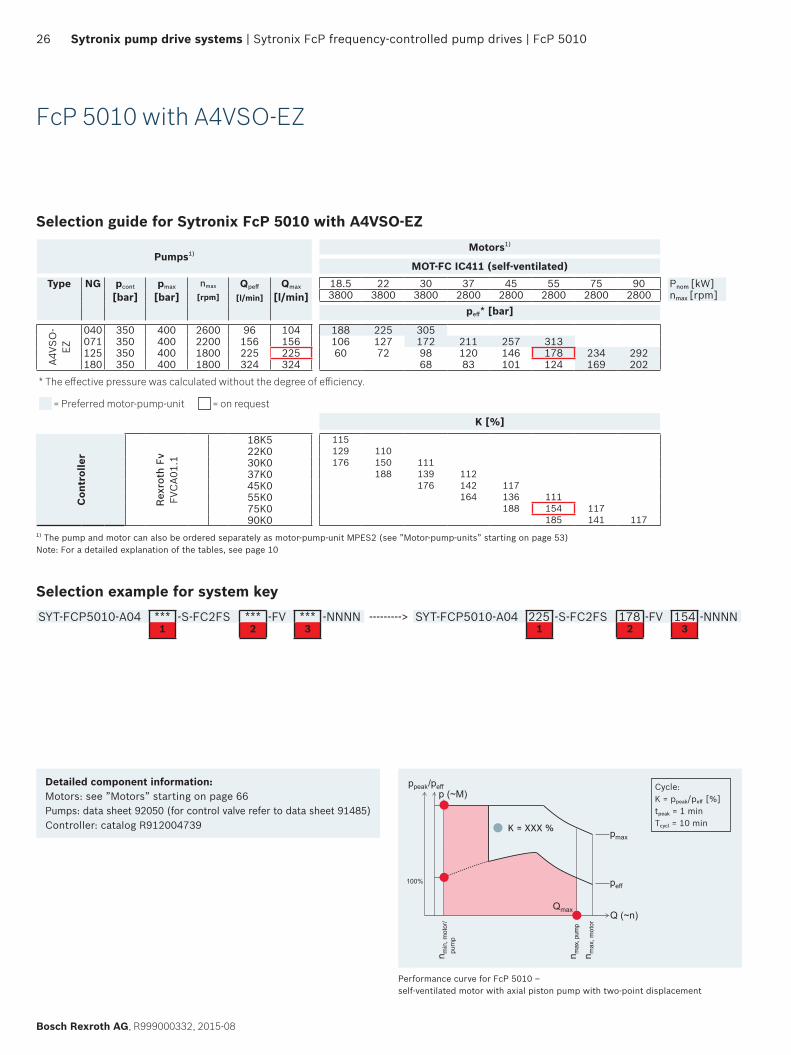
Selection example for system keySYT-FCP5010-A04 *** -S-FC2FS *** -FV *** -NNNN ---------> SYT-FCP5010-A04 225 -S-FC2FS 178 -FV 154 -NNNN
1 2 3 1 2 3
FcP 5010 with A4VSO-EZ
Sytronix SvP servo-variable pump drives | Sytronix pump drive systems 27
R999000332, 2015-08, Bosch Rexroth AG
Sytronix SvP servo-variable pump drives
SvP systemSytronix SvP (servo-variable pump drive) 7010 systems consist of a motor-pump-unit driven by a permanent magnet synchronous servo motor and servo controller. Whereas, the SvP 5010 systems. which have been designed for the Asian market only, consist of a motor-pump-unit driven by an asynchronous servo motor and a frequency converter.
In the family of Sytronix variable-speed pump drives, the Sytronix SvP offers the highest dynamic performance and control accuracy. SvP systems provide the broadest range of control functionality, from pressure and force control to flow and speed control to position control and alternating control.
SvP 7010 and SvP 5010 utilize different VFD drive electronics: respectively IndraDrive controller and Rexroth Fv. Differences between both types include the type and scope of communi-cation and bus interfaces, as well as additional functionality and user interfaces.
The controller for the SvP 7010 family is part of Rexroth’s IndraDrive family using the IndraWorks engineering tool as the interface. In addition to traditional hydraulic control functionality, the SvP system provides further functions of pressure ripple compensation, energy monitoring, condition monitoring, as well as maintenance and troubleshooting aids.
The SvP 7010 system can be configured for required com-munication interfaces by exchanging the CSH controller. The command and actual values of pressure, flow and position can then be commanded and monitored by a high level machine control system using either an analog interface or industry standard bus interface, thus providing an easy and flexible integration into machine control systems.
Components f Hydraulic pump f Synchronous servo motor (SvP 7010) f IndraDrive servo controller (SvP 7010) f Asynchronous servo motor (SvP 5010) f Rexroth Fv frequency converter (SvP 5010) f Pressure transducer
ApplicationsThe system is suitable for use in either open or closed hydraulic systems controlling hydraulic axes.
28 Sytronix pump drive systems | Sytronix SvP servo-variable pump drives
Bosch Rexroth AG, R999000332, 2015-08
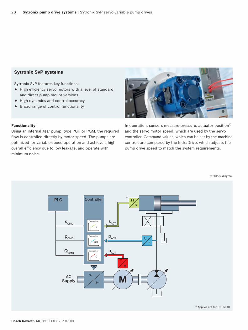
FunctionalityUsing an internal gear pump, type PGH or PGM, the required flow is controlled directly by motor speed. The pumps are optimized for variable-speed operation and achieve a high overall efficiency due to low leakage, and operate with minimum noise.
In operation, sensors measure pressure, actuator position1) and the servo motor speed, which are used by the servo controller. Command values, which can be set by the machine control, are compared by the IndraDrive, which adjusts the pump drive speed to match the system requirements.
Sytronix SvP systems
Sytronix SvP features key functions: f High efficiency servo motors with a level of standard
and direct pump mount versions f High dynamics and control accuracy f Broad range of control functionality
sController
1)PLC
Controller
s
Controller
Q
Controller
p/F
pACT
QCMD
pCMD
sCMD
ACSupply
3~
3~ Mn
nACT
sACT
Up
n
SvP block diagram
1) Applies not for SvP 5010
SvP 7010 | Sytronix SvP servo-variable pump drives | Sytronix pump drive systems 29
R999000332, 2015-08, Bosch Rexroth AG
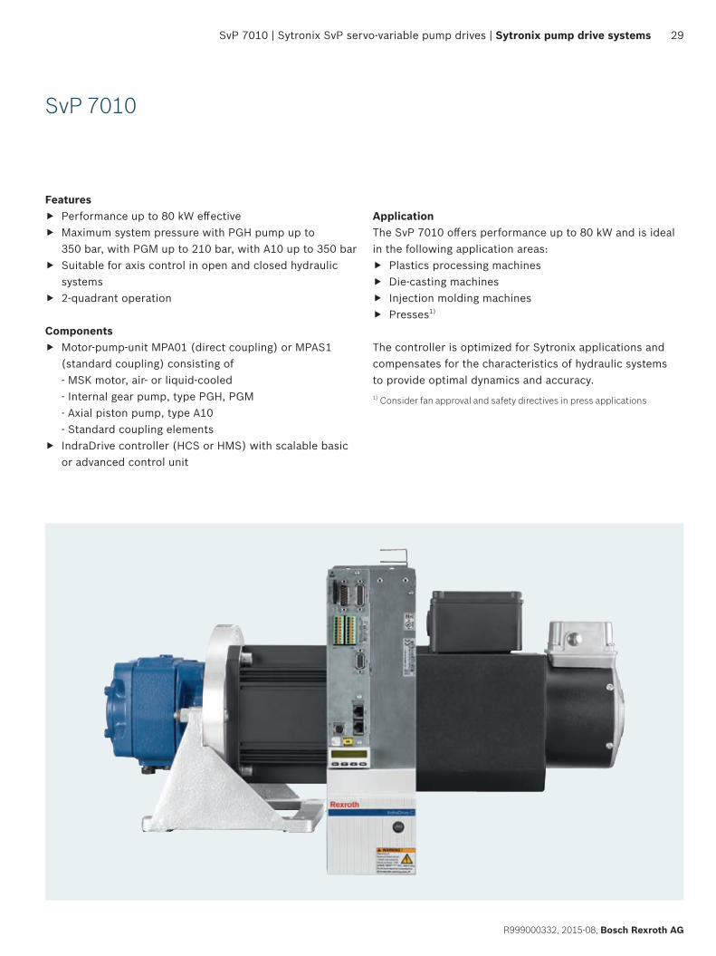
SvP 7010
ApplicationThe SvP 7010 offers performance up to 80 kW and is ideal in the following application areas:
f Plastics processing machines f Die-casting machines f Injection molding machines f Presses1)
The controller is optimized for Sytronix applications and compensates for the characteristics of hydraulic systems to provide optimal dynamics and accuracy.1) Consider fan approval and safety directives in press applications
Features f Performance up to 80 kW effective f Maximum system pressure with PGH pump up to
350 bar, with PGM up to 210 bar, with A10 up to 350 bar f Suitable for axis control in open and closed hydraulic
systems f 2-quadrant operation
Components f Motor-pump-unit MPA01 (direct coupling) or MPAS1
(standard coupling) consisting of - MSK motor, air- or liquid-cooled - Internal gear pump, type PGH, PGM - Axial piston pump, type A10 - Standard coupling elements
f IndraDrive controller (HCS or HMS) with scalable basic or advanced control unit
30 Sytronix pump drive systems | Sytronix SvP servo-variable pump drives | SvP 7010
Bosch Rexroth AG, R999000332, 2015-08
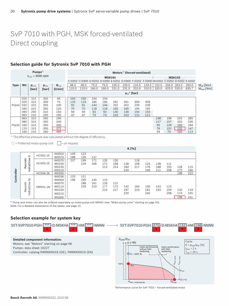
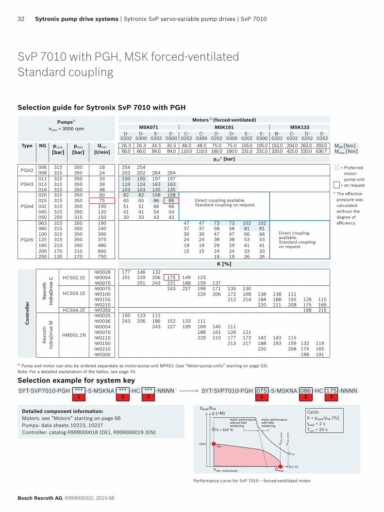
SvP 7010 with PGH, MSK forced-ventilatedDirect coupling
Selection guide for Sytronix SvP 7010 with PGHPumps1)
nmax = 3000 rpmMotors 1) (forced-ventilated)
MSK101 MSK133C-0202 C-0300 D-0202 D-0300 E-0202 E-0300 F-0202 F-0300 B-0202 C-0202 D-0202 E-0202
Type NG pcont.
[bar]pmax
[bar]Qmax
[l/min]48.0 48.0 75.0 75.0 105.0 105.0 124.5 124.5 152.0 204.0 263.0 293.0 Meff [Nm]110.0 110.0 160.0 160.0 231.0 231.0 310.0 310.0 320.0 425.0 520.0 630.7 Mmax [Nm]
peff* [bar]
PGH4
020 315 350 60 150 150 234 234025 315 350 75 119 119 186 186 261 261 309 309032 315 350 100 92 92 144 144 202 202 239 239040 315 350 120 75 75 118 118 165 165 195 195050 250 310 150 59 59 93 93 130 130 154 154063 210 250 190 47 47 73 73 102 102 121 121
PGH5
063 315 350 190 148 198 255 285080 315 350 240 117 157 203 226100 315 350 300 95 128 165 184125 315 350 375 76 102 132 147160 210 260 480 59 79 102 113
* The effective pressure was calculated without the degree of efficiency.
= Preferred motor-pump-unit = on request
K [%]
Con
trol
ler R
exro
th
Indr
aDri
ve C HCS02.1E -W0054 149 123
-W0070 188 159 137
HCS03.1E-W0070 227 199 171 135 130 118-W0100 229 206 172 168 138 158 125 138 111-W0150 212 214 184 217 176 188 155 128 115-W0210 220 246 211 208 175 166
HCS04.2E -W0350 198 215
Rexr
oth
Indr
aDri
ve M
HMS01.1N
-W0036 133 111-W0054 199 169 145 110-W0070 188 161 126 121-W0110 229 210 177 173 142 164 130 143 115-W0150 213 217 187 223 181 193 159 132 119-W0210 220 245 208 174 165-W0300 198 191
1) Pump and motor can also be ordered separately as motor-pump-unit MPA01 (see ”Motor-pump-units” starting on page 53). Note: For a detailed explanation of the tables, see page 10.
Selection example for system keySYT-SVP7010-PGH *** -D-MSKHA *** -HM *** -NNNN ---------> SYT-SVP7010-PGH 375 -D-MSKHA 132 -HM 198 -NNNN
1 2 3 1 2 3
Detailed component information:Motors: see ”Motors” starting on page 66Pumps: data sheet 10227Controller: catalog R999000018 (DE), R999000019 (EN)
motor performancewith fieldweakening
n max
, pum
p
n max
, mot
or
pmax
Q (~n)
peff
motor performance without fieldweakening
100%
Qmaxnmin, motor/pump
ppeak/peffp (~M)
Performance curve for SvP 7010 – forced-ventilated motor
Cycle:K = ppeak/peff [%]tpeak = 2 sTcycl = 20 s
SvP 7010 | Sytronix SvP servo-variable pump drives | Sytronix pump drive systems 31
R999000332, 2015-08, Bosch Rexroth AG
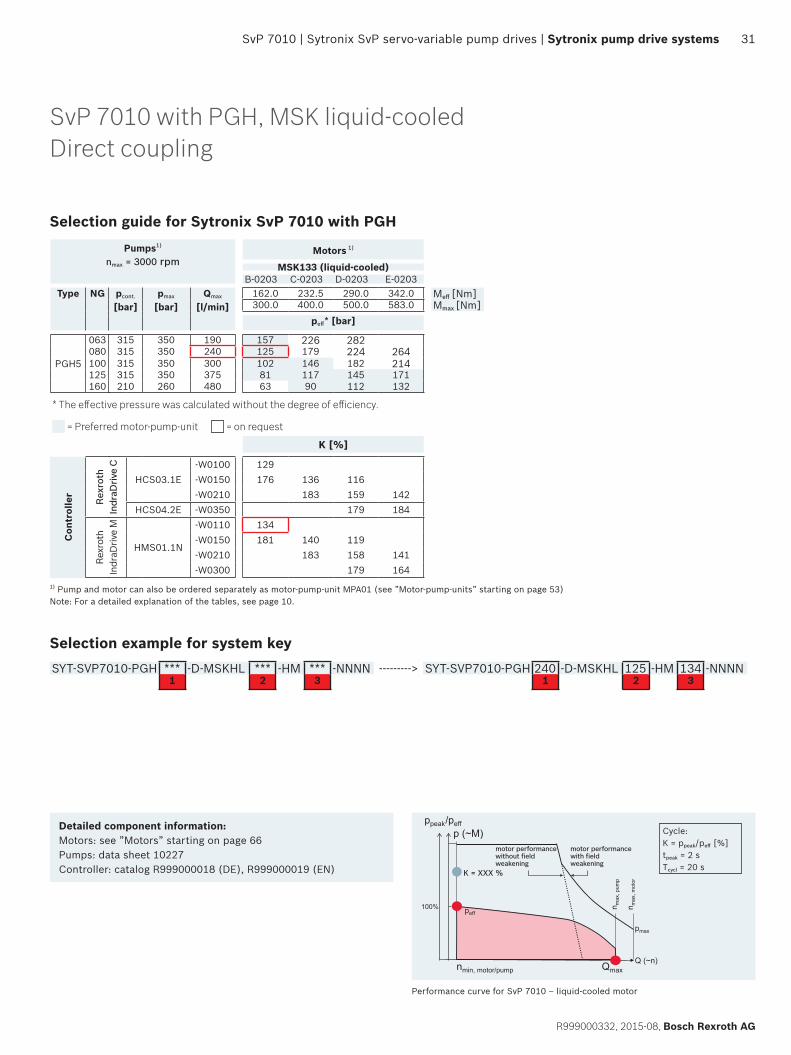
SvP 7010 with PGH, MSK liquid-cooledDirect coupling
Selection guide for Sytronix SvP 7010 with PGHPumps1)
nmax = 3000 rpmMotors 1)
MSK133 (liquid-cooled)B-0203 C-0203 D-0203 E-0203
Type NG pcont.
[bar]pmax
[bar]Qmax
[l/min]162.0 232.5 290.0 342.0 Meff [Nm]300.0 400.0 500.0 583.0 Mmax [Nm]
peff* [bar]
PGH5
063 315 350 190 157 226 282080 315 350 240 125 179 224 264100 315 350 300 102 146 182 214125 315 350 375 81 117 145 171160 210 260 480 63 90 112 132
* The effective pressure was calculated without the degree of efficiency.
= Preferred motor-pump-unit = on request
K [%]
Con
trol
ler
Rexr
oth
Indr
aDriv
e C
HCS03.1E-W0100 129-W0150 176 136 116-W0210 183 159 142
HCS04.2E -W0350 179 184
Rexr
oth
Indr
aDriv
e M
HMS01.1N
-W0110 134-W0150 181 140 119-W0210 183 158 141-W0300 179 164
1) Pump and motor can also be ordered separately as motor-pump-unit MPA01 (see ”Motor-pump-units” starting on page 53) Note: For a detailed explanation of the tables, see page 10.
Selection example for system keySYT-SVP7010-PGH *** -D-MSKHL *** -HM *** -NNNN ---------> SYT-SVP7010-PGH 240 -D-MSKHL 125 -HM 134 -NNNN
1 2 3 1 2 3
Detailed component information:Motors: see ”Motors” starting on page 66Pumps: data sheet 10227Controller: catalog R999000018 (DE), R999000019 (EN)
motor performancewith fieldweakening
n max
, pum
p
n max
, mot
or
pmax
Q (~n)
peff
motor performance without fieldweakening
100%
Qmaxnmin, motor/pump
ppeak/peffp (~M)
Performance curve for SvP 7010 – liquid-cooled motor
Cycle:K = ppeak/peff [%]tpeak = 2 sTcycl = 20 s
32 Sytronix pump drive systems | Sytronix SvP servo-variable pump drives | SvP 7010
Bosch Rexroth AG, R999000332, 2015-08
SvP 7010 with PGH, MSK forced-ventilatedStandard coupling
Selection guide for Sytronix SvP 7010 with PGH
Pumps1)
nmax = 3000 rpm
Motors 1) (forced-ventilated)MSK071 MSK101 MSK133
D-0202
D-0300
E-0202
E-0300
C-0202
C-0300
D-0202
D-0300
E-0202
E-0300
B-0202
C-0202
D-0202
E-0202
Type NG pcont.
[bar]pmax
[bar]Qmax
[l/min]26.3 26.3 34.5 35.5 48.0 48.0 75.0 75.0 105.0 105.0 152.0 204.0 263.0 293.0 Meff [Nm]66.0 66.0 84.0 84.0 110.0 110.0 160.0 160.0 231.0 231.0 320.0 425.0 520.0 630.7 Mmax [Nm]
peff* [bar]
PGH2 006 315 350 18 254 254008 315 350 24 202 202 264 264
PGH3011 315 350 33 150 150 197 197013 315 350 39 124 124 163 163016 315 350 48 103 103 135 135
PGH4
020 315 350 60 82 82 108 108025 315 350 75 65 65 86 86 Direct coupling available.
Standard coupling on request.032 315 350 100 51 51 66 66040 315 350 120 41 41 54 54050 250 315 150 33 33 43 43
PGH5
063 315 350 190 47 47 73 73 102 102080 315 350 240 37 37 58 58 81 81
Direct coupling available.Standard coupling on request.
100 315 350 300 30 30 47 47 66 66125 315 350 375 24 24 38 38 53 53160 210 260 480 19 19 29 29 41 41200 170 210 600 15 15 24 24 33 33250 135 170 750 19 19 26 26
K [%]
Con
trol
ler
Rex
roth
In
draD
rive
C HCS02.1E-W0028 177 146 132-W0054 251 229 206 175 149 123-W0070 251 243 221 188 159 137
HCS03.1E-W0070 243 227 199 171 135 130-W0100 229 206 172 168 138 138 111-W0150 212 214 184 188 155 128 115-W0210 220 211 208 175 166
HCS04.2E -W0350 198 215
Rexr
oth
Indr
aDri
ve M
HMS01.1N
-W0020 150 123 112-W0036 243 206 186 152 133 111-W0054 243 227 199 169 145 111-W0070 188 161 126 121-W0110 229 210 177 173 142 143 115-W0150 213 217 188 193 159 132 119-W0210 220 208 174 165-W0300 198 191
1) Pump and motor can also be ordered separately as motor-pump-unit MPAS1 (see ”Motor-pump-units” starting on page 53). Note: For a detailed explanation of the tables, see page 10.
Selection example for system keySYT-SVP7010-PGH *** -S-MSKNA *** -HC *** -NNNN ---------> SYT-SVP7010-PGH 075 -S-MSKNA 086 -HC 175 -NNNN
1 2 3 1 2 3
Detailed component information:Motors: see ”Motors” starting on page 66Pumps: data sheets 10223, 10227Controller: catalog R999000018 (DE), R999000019 (EN)
Performance curve for SvP 7010 – forced-ventilated motor
motor performancewith fieldweakening
n max
, pum
p
n max
, mot
or
pmax
Q (~n)
peff
motor performance without fieldweakening
100%
Qmaxnmin, motor/pump
ppeak/peffp (~M) Cycle:
K = ppeak/peff [%]tpeak = 2 sTcycl = 20 s
= Preferred motor- pump-unit
= on request
* The effective pressure was calculated without the degree of efficiency.
SvP 7010 | Sytronix SvP servo-variable pump drives | Sytronix pump drive systems 33
R999000332, 2015-08, Bosch Rexroth AG
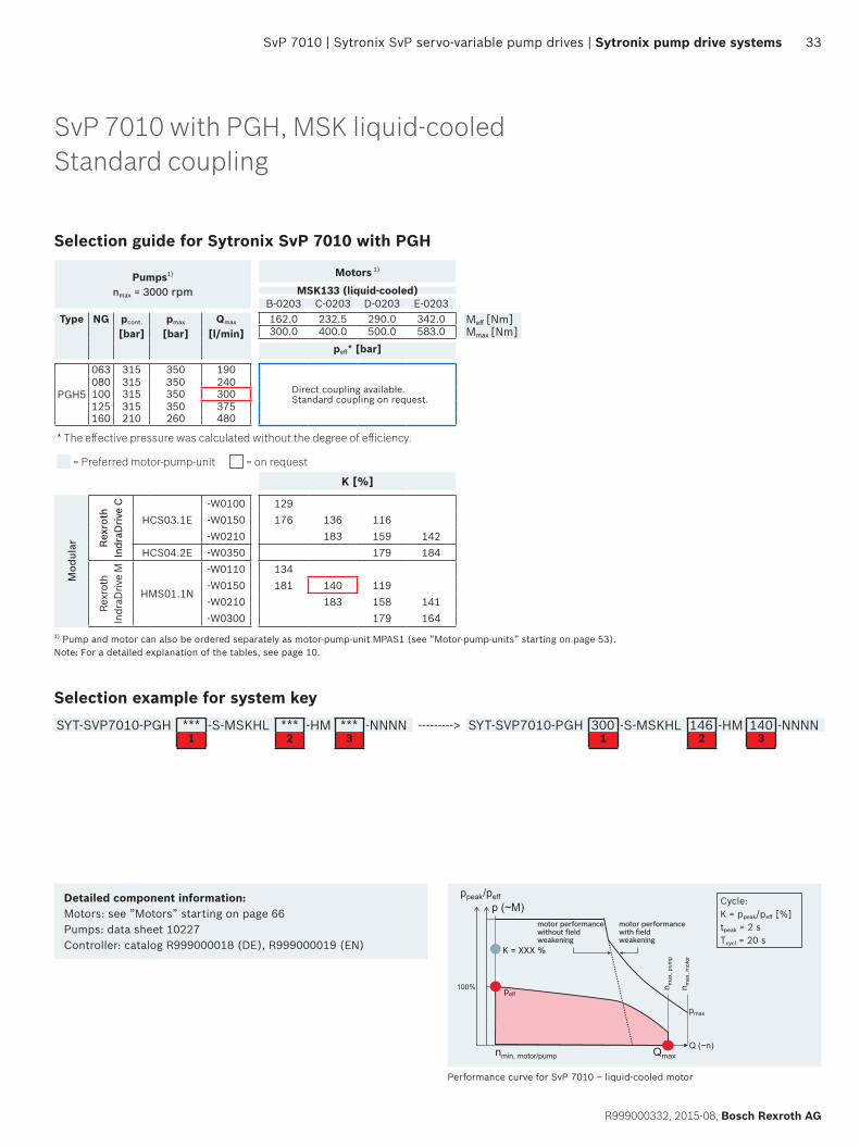
SvP 7010 with PGH, MSK liquid-cooledStandard coupling
Selection guide for Sytronix SvP 7010 with PGH
Pumps1)
nmax = 3000 rpm
Motors 1)
MSK133 (liquid-cooled)B-0203 C-0203 D-0203 E-0203
Type NG pcont.
[bar]pmax
[bar]Qmax
[l/min]162.0 232.5 290.0 342.0 Meff [Nm]300.0 400.0 500.0 583.0 Mmax [Nm]
peff* [bar]
PGH5
063 315 350 190
Direct coupling available.Standard coupling on request.
080 315 350 240100 315 350 300125 315 350 375160 210 260 480
* The effective pressure was calculated without the degree of efficiency.
= Preferred motor-pump-unit = on request
K [%]
Mod
ular Re
xrot
h In
draD
rive
C
HCS03.1E-W0100 129-W0150 176 136 116-W0210 183 159 142
HCS04.2E -W0350 179 184
Rexr
oth
Indr
aDriv
e M
HMS01.1N
-W0110 134-W0150 181 140 119-W0210 183 158 141-W0300 179 164
1) Pump and motor can also be ordered separately as motor-pump-unit MPAS1 (see ”Motor-pump-units” starting on page 53). Note: For a detailed explanation of the tables, see page 10.
Selection example for system keySYT-SVP7010-PGH *** -S-MSKHL *** -HM *** -NNNN ---------> SYT-SVP7010-PGH 300 -S-MSKHL 146 -HM 140 -NNNN
1 2 3 1 2 3
Detailed component information:Motors: see ”Motors” starting on page 66Pumps: data sheet 10227Controller: catalog R999000018 (DE), R999000019 (EN)
motor performancewith fieldweakening
n max
, pum
p
n max
, mot
or
pmax
Q (~n)
peff
motor performance without fieldweakening
100%
Qmaxnmin, motor/pump
ppeak/peffp (~M) Cycle:
K = ppeak/peff [%]tpeak = 2 sTcycl = 20 s
Performance curve for SvP 7010 – liquid-cooled motor
34 Sytronix pump drive systems | Sytronix SvP servo-variable pump drives | SvP 7010
Bosch Rexroth AG, R999000332, 2015-08
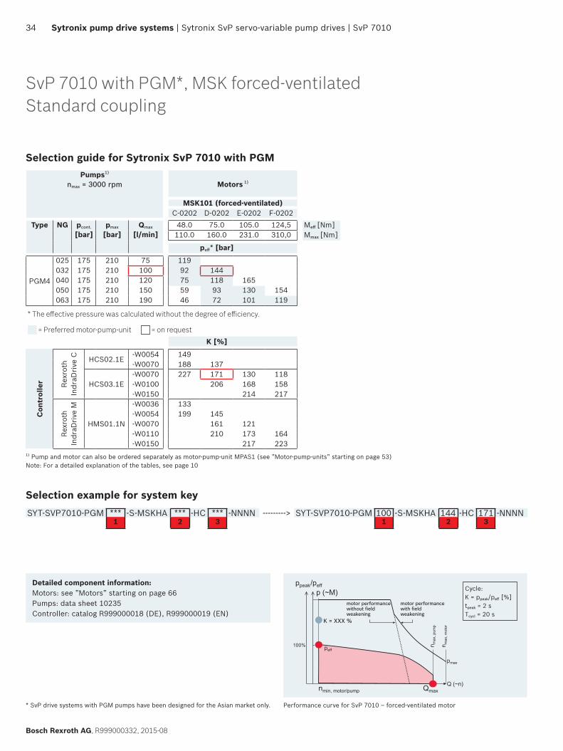
SvP 7010 with PGM*, MSK forced-ventilatedStandard coupling
Selection guide for Sytronix SvP 7010 with PGMPumps1)
nmax = 3000 rpm Motors 1)
MSK101 (forced-ventilated)C-0202 D-0202 E-0202 F-0202
Type NG pcont.
[bar]pmax
[bar]Qmax
[l/min]48.0 75.0 105.0 124,5 Meff [Nm]
110.0 160.0 231.0 310,0 Mmax [Nm]
peff* [bar]
PGM4
025 175 210 75 119032 175 210 100 92 144040 175 210 120 75 118 165050 175 210 150 59 93 130 154063 175 210 190 46 72 101 119
* The effective pressure was calculated without the degree of efficiency.
= Preferred motor-pump-unit = on request
K [%]
Con
trol
ler Re
xrot
h In
draD
rive
C HCS02.1E-W0054 149-W0070 188 137
HCS03.1E-W0070 227 171 130 118-W0100 206 168 158-W0150 214 217
Rexr
oth
Indr
aDriv
e M
HMS01.1N
-W0036 133-W0054 199 145-W0070 161 121-W0110 210 173 164-W0150 217 223
1) Pump and motor can also be ordered separately as motor-pump-unit MPAS1 (see ”Motor-pump-units” starting on page 53) Note: For a detailed explanation of the tables, see page 10
Selection example for system keySYT-SVP7010-PGM *** -S-MSKHA *** -HC *** -NNNN ---------> SYT-SVP7010-PGM 100 -S-MSKHA 144 -HC 171 -NNNN
1 2 3 1 2 3
motor performancewith fieldweakening
n max
, pum
p
n max
, mot
or
pmax
Q (~n)
peff
motor performance without fieldweakening
100%
Qmaxnmin, motor/pump
ppeak/peffp (~M)
Performance curve for SvP 7010 – forced-ventilated motor
Cycle:K = ppeak/peff [%]tpeak = 2 sTcycl = 20 s
Detailed component information:Motors: see ”Motors” starting on page 66Pumps: data sheet 10235Controller: catalog R999000018 (DE), R999000019 (EN)
* SvP drive systems with PGM pumps have been designed for the Asian market only.
SvP 7010 | Sytronix SvP servo-variable pump drives | Sytronix pump drive systems 35
R999000332, 2015-08, Bosch Rexroth AG
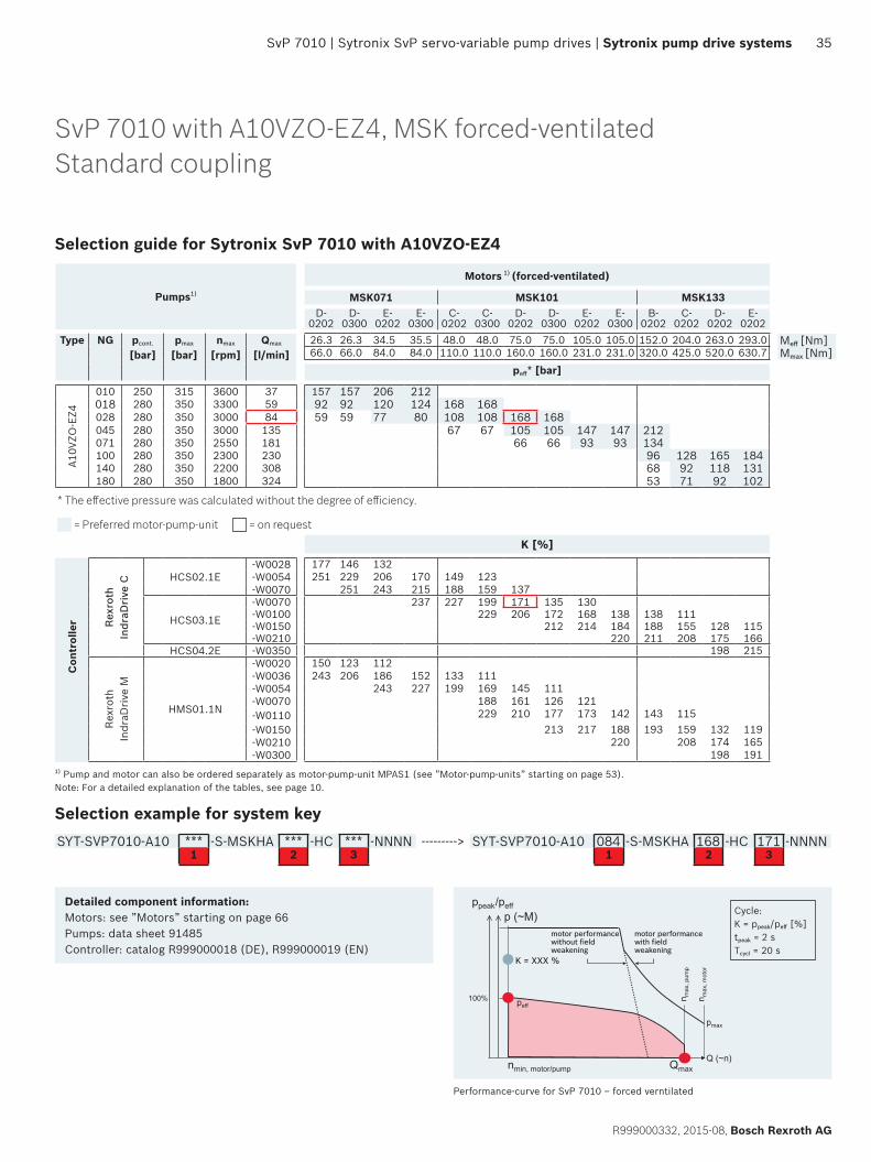
SvP 7010 with A10VZO-EZ4, MSK forced-ventilatedStandard coupling
motor performancewith fieldweakening
n max
, pum
p
n max
, mot
or
pmax
Q (~n)
peff
motor performance without fieldweakening
100%
Qmaxnmin, motor/pump
ppeak/peffp (~M)
Performance-curve for SvP 7010 – forced verntilated
Cycle:K = ppeak/peff [%]tpeak = 2 sTcycl = 20 s
Detailed component information:Motors: see ”Motors” starting on page 66Pumps: data sheet 91485Controller: catalog R999000018 (DE), R999000019 (EN)
Selection guide for Sytronix SvP 7010 with A10VZO-EZ4
Pumps1)
Motors 1) (forced-ventilated)
MSK071 MSK101 MSK133D-
0202D-
0300E-
0202E-
0300C-
0202C-
0300D-
0202D-
0300E-
0202E-
0300B-
0202C-
0202D-
0202E-
0202Type NG pcont.
[bar]pmax
[bar]nmax
[rpm]Qmax
[l/min]26.3 26.3 34.5 35.5 48.0 48.0 75.0 75.0 105.0 105.0 152.0 204.0 263.0 293.0 Meff [Nm]66.0 66.0 84.0 84.0 110.0 110.0 160.0 160.0 231.0 231.0 320.0 425.0 520.0 630.7 Mmax [Nm]
peff* [bar]
A10V
ZO-E
Z4
010 250 315 3600 37 157 157 206 212018 280 350 3300 59 92 92 120 124 168 168028 280 350 3000 84 59 59 77 80 108 108 168 168045 280 350 3000 135 67 67 105 105 147 147 212071 280 350 2550 181 66 66 93 93 134100 280 350 2300 230 96 128 165 184140 280 350 2200 308 68 92 118 131180 280 350 1800 324 53 71 92 102
* The effective pressure was calculated without the degree of efficiency.
= Preferred motor-pump-unit = on request
K [%]
Con
trol
ler Rex
roth
Indr
aDri
ve C HCS02.1E
-W0028 177 146 132-W0054 251 229 206 170 149 123-W0070 251 243 215 188 159 137
HCS03.1E
-W0070 237 227 199 171 135 130-W0100 229 206 172 168 138 138 111-W0150 212 214 184 188 155 128 115-W0210 220 211 208 175 166
HCS04.2E -W0350 198 215
Rexr
oth
Indr
aDri
ve M
HMS01.1N
-W0020 150 123 112-W0036 243 206 186 152 133 111-W0054 243 227 199 169 145 111-W0070 188 161 126 121-W0110 229 210 177 173 142 143 115-W0150 213 217 188 193 159 132 119-W0210 220 208 174 165-W0300 198 191
1) Pump and motor can also be ordered separately as motor-pump-unit MPAS1 (see ”Motor-pump-units” starting on page 53). Note: For a detailed explanation of the tables, see page 10.
Selection example for system keySYT-SVP7010-A10 *** -S-MSKHA *** -HC *** -NNNN ---------> SYT-SVP7010-A10 084 -S-MSKHA 168 -HC 171 -NNNN
1 2 3 1 2 3
36 Sytronix pump drive systems | Sytronix SvP servo-variable pump drives | SvP 7010
Bosch Rexroth AG, R999000332, 2015-08
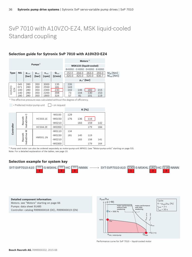
SvP 7010 with A10VZO-EZ4, MSK liquid-cooledStandard coupling
Detailed component information:Motors: see ”Motors” starting on page 66Pumps: data sheet 91485Controller: catalog R999000018 (DE), R999000019 (EN)
Selection guide for Sytronix SvP 7010 with A10VZO-EZ4
Pumps1)
Motors 1)
MSK133 (liquid-cooled)B-0202 C-0202 D-0202 E-0202
Type NG pcont.
[bar]pmax
[bar]nmax
[rpm]Qmax
[l/min]152.0 204.0 263.0 293.0 Meff [Nm]320.0 425.0 520.0 630.7 Mmax [Nm]
peff* [bar]
A10V
ZO-
EZ4
045 280 350 3000 135 226071 280 350 2550 181 143100 280 350 2300 230 102 146 182 215140 280 350 2200 308 73 104 130 153180 280 350 1800 324 57 81 101 119
* The effective pressure was calculated without the degree of efficiency.
= Preferred motor-pump-unit = on request
K [%]
Con
trol
ler Rex
roth
In
draD
rive
C
HCS03.1E
-W0100 129-W0150 176 136 116-W0210 183 159 142
HCS04.2E -W0350 179 184
Rex
roth
In
draD
rive
M
HMS01.1N
-W0110 134
-W0150 181 140 119
-W0210 183 158 141
-W0300 179 1641) Pump and motor can also be ordered separately as motor-pump-unit MPAS1 (see ”Motor-pump-units” starting on page 53). Note: For a detailed explanation of the tables, see page 10.
Selection example for system keySYT-SVP7010-A10 *** -S-MSKHL *** -HC *** -NNNN ---------> SYT-SVP7010-A10 230 -S-MSKHL 182 -HC 116 -NNNN
1 2 3 1 2 3
motor performancewith fieldweakening
n max
, pum
p
n max
, mot
or
pmax
Q (~n)
peff
motor performance without fieldweakening
100%
Qmaxnmin, motor/pump
ppeak/peffp (~M)
Performance curve for SvP 7010 – liquid-cooled motor
Cycle:K = ppeak/peff [%]tpeak = 2 sTcycl = 20 s
SvP 5010 | Sytronix SvP servo-variable pump drives | Sytronix pump drive systems 37
R999000332, 2015-08, Bosch Rexroth AG
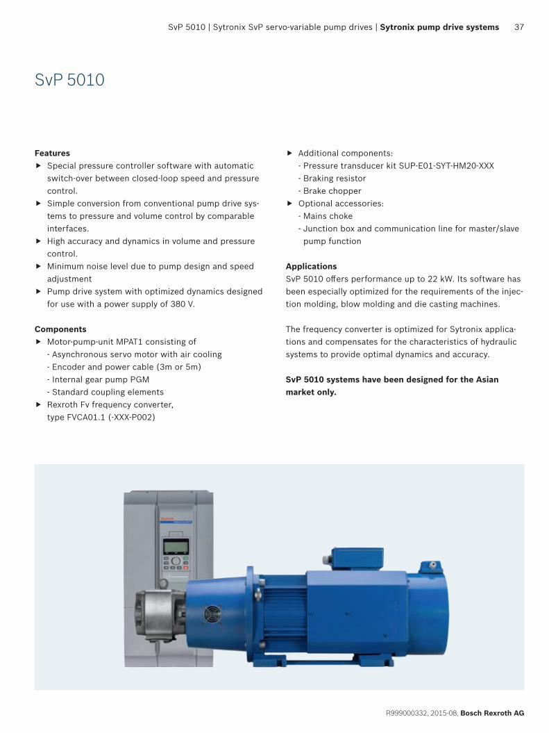
SvP 5010
Features f Special pressure controller software with automatic
switch-over between closed-loop speed and pressure control.
f Simple conversion from conventional pump drive sys-tems to pressure and volume control by comparable interfaces.
f High accuracy and dynamics in volume and pressure control.
f Minimum noise level due to pump design and speed adjustment
f Pump drive system with optimized dynamics designed for use with a power supply of 380 V.
Components f Motor-pump-unit MPAT1 consisting of
- Asynchronous servo motor with air cooling - Encoder and power cable (3m or 5m) - Internal gear pump PGM - Standard coupling elements
f Rexroth Fv frequency converter, type FVCA01.1 (-XXX-P002)
f Additional components: - Pressure transducer kit SUP-E01-SYT-HM20-XXX - Braking resistor - Brake chopper
f Optional accessories: - Mains choke - Junction box and communication line for master/slave pump function
ApplicationsSvP 5010 offers performance up to 22 kW. Its software has been especially optimized for the requirements of the injec-tion molding, blow molding and die casting machines.
The frequency converter is optimized for Sytronix applica-tions and compensates for the characteristics of hydraulic systems to provide optimal dynamics and accuracy.
SvP 5010 systems have been designed for the Asian market only.
38 Sytronix pump drive systems | Sytronix SvP servo-variable pump drives | SvP 5010
Bosch Rexroth AG, R999000332, 2015-08
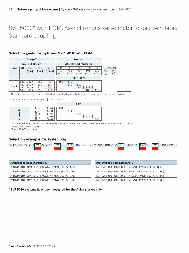
Selection guide for Sytronix SvP 5010 with PGMPumps1) Motors1)
nmax = 3000 rpm MAS (forced-ventilated)Type NG pcont
[bar]pmax
[bar]Qmax
[l/min]9 13 15 18.5 22 Pnom
2) [kW]
50 71.5 71 101 120 Mnom [Nm]8000 6000 6000 6000 6000 nmax [rpm]
peff* [bar]
PGM43)
032 3000 210 80 100 140040 3000 210 100 112 112050 3000 210 120 90 127063 3000 210 150 100 120
* The effective pressure was calculated without the degree of efficiency of pump and motor (around 80%)
= Preferred motor-pump-unit = on request
K [%]
Con
trol
ler
Rex
roth
Fv
FVC
A01.
1 11K0 13415K0 12418K5 13022K0 12230K0 142
1) The pump and motor can also be ordered separately as motor-pump-unit MPAT1 (see ”Motor-pump-units starting on page 53)2) Higher power range on request3) PGM4-4X/NG25 on request
Selection example for system keySYT-SVP5010-PGM *** -S-FC2FS *** -FV *** -000 ---------> SYT-SVP5010-PGM 120 -S-REAGA 127 -FV 122 -0001 (120S)
1 2 3 1 2 3
SvP 5010* with PGM, Asynchronous servo motor forced-ventilated Standard coupling
Performance class Standard -S
SYTSVP5010-PGM080-S-REAGA140-FV124-0001/2(80S)
SYTSVP5010-PGM100-S-REAHA112-FV130-0001/2(100S)
SYTSVP5010-PGM120-S-REAGA127-FV122-0001/2(120S)
SYTSVP5010-PGM150-S-REAGA120-FV142-0001/2(150S)
Performance class Standard -E
SYT-SVP5010-PGM080-S-REAGA100-FV134-0001/2 (80E)
SYT-SVP5010-PGM100-S-REAGA112-FV124-0001/2 (100E)
SYT-SVP5010-PGM120-S-REAHA090-FV130-0001/2 (120E)
SYT-SVP5010-PGM150-S-REAGA100-FV122-0001/2 (150E)
* SvP 5010 systems have been designed for the Asian market only.
Sytronix DFE variable-speed pressure and flow control electronically | Sytronix pump drive systems 39
R999000332, 2015-08, Bosch Rexroth AG
DFE systemsSytronix DFE systems consist of an electrohydraulically controlled axial piston pump, driven by a variable-speed asynchronous motor
Pump drives DFE 5010 and DFE 7010 are based on the proven DFE pressure and flow pump control system.
Using industry standard inverter duty motors, up to 315 kW, results in a high price/performance ratio and high perfor-mance capabilities.
When using the ”teach-in” version, the machine cycle pres-sure and flow profile is stored in the DFE control electronics. This allows the DFE system to accelerate the electric motor ahead of a required flow demand.
In machines operating without a predictable operating cycle, such as wood and metallurgy applications, a ”real-time” mode can be used. The DFE controller calculates an optimal combination of motor speed and pump swivel angle to maximize energy savings.
Identical mechanical interfaces permit cost-effective retro-fitting, e.g. of a DFE 5010, as a replacement for a SYDFEE/SYDFEC by simply exchanging the integrated pump valve electronics.
The control system is available for A10 and A4 pumps and can thus be used for a wide variety of applications.
Components f Axial piston variable pump with integrated control elec-
tronics f MOT-FC standard asynchronous motor f VFD to control motor speed f Pressure transducer
ApplicationsSytronix DFE is suitable for use in open hydraulic systems, with one or multiple hydraulic consumers, for control of pressure and flow.
Sytronix DFE variable-speed pressure and flow control electronically
40 Sytronix pump drive systems | Sytronix DFE variable-speed pressure and flow control electronically
Bosch Rexroth AG, R999000332, 2015-08
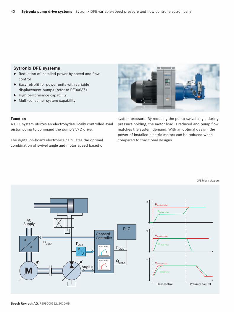
Sytronix DFE systems f Reduction of installed power by speed and flow
control f Easy retrofit for power units with variable
displacement pumps (refer to RE30637) f High performance capability f Multi-consumer system capability
FunctionA DFE system utilizes an electrohydraulically controlled axial piston pump to command the pump’s VFD drive.
The digital on-board electronics calculates the optimal combination of swivel angle and motor speed based on
system pressure. By reducing the pump swivel angle during pressure holding, the motor load is reduced and pump flow matches the system demand. With an optimal design, the power of installed electric motors can be reduced when compared to traditional designs.
M
PU
Onboard-Controller
Controller
Q
Controller
p
pACTnCMD
ACSupply
3~
3~
Angle α
PLC
pCMD
QCMD
αnominal value
α
nnominal value
n
pnominal value
αactual value
nactual value
pactual value
p
Flow control Pressure control
DFE block diagram
DFE 7010 | Sytronix DFE variable-speed pressure and flow control electronically | Sytronix pump drive systems 41
R999000332, 2015-08, Bosch Rexroth AG
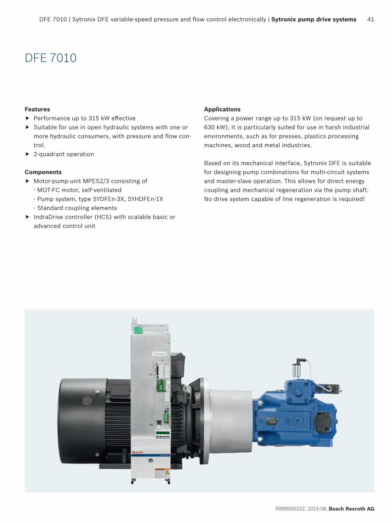
DFE 7010
Features f Performance up to 315 kW effective f Suitable for use in open hydraulic systems with one or
more hydraulic consumers, with pressure and flow con-trol.
f 2-quadrant operation
Components f Motor-pump-unit MPES2/3 consisting of
- MOT-FC motor, self-ventilated - Pump system, type SYDFEn-3X, SYHDFEn-1X - Standard coupling elements
f IndraDrive controller (HCS) with scalable basic or advanced control unit
ApplicationsCovering a power range up to 315 kW (on request up to 630 kW), it is particularly suited for use in harsh industrial environments, such as for presses, plastics processing machines, wood and metal industries.
Based on its mechanical interface, Sytronix DFE is suitable for designing pump combinations for multi-circuit systems and master-slave operation. This allows for direct energy coupling and mechanical regeneration via the pump shaft. No drive system capable of line regeneration is required!
42 Sytronix pump drive systems | Sytronix DFE variable-speed pressure and flow control electronically | DFE 7010
Bosch Rexroth AG, R999000332, 2015-08
DFE 7010 with SYDFEn-3X (A10VSO)
Selection guide for Sytronix DFE 7010 with SYDFEn-3X (A10VSO)
Pumps1) Motors1)
MOT-FC IC411 (self-ventilated)Type NG pcont
[bar]pmax
[bar]nmax
[rpm]Qmax
[l/min]4 5.5 7.5 11 15 18.5 22 30 37 45 55 75 90 Pnom [kW]
4000 4000 4000 3800 3800 3800 3800 3800 2800 2800 2800 2800 2800 nmax [rpm]
peff* [bar]
A10VSO
071 280 350 2550 181 23 32 43 64 87 106 126 171 210 256100 280 350 2300 230 23 31 45 62 75 90 122 150 182 222140 280 350 2200 308 22 32 44 54 64 87 107 130 159 217 260180 280 350 1800 324 25 34 42 50 68 83 101 124 169 202
* The effective pressure was calculated without the degree of efficiency.
= Preferred motor-pump-unit = on request
K [%]
Con
trol
ler
Rexr
oth
Indr
aDri
ve C HCS01.1E -W0028 146 105
-W0054 191 140 100HCS02.1E -W0070 187 133 100
HCS03.1E
-W0070 161 132 113-W0100 183 135 109-W0150 176 142 117-W0210 179 146 112
HCS04.2E -W0350 189 158-W0420 192
1) The pump and motor can also be ordered separately as motor-pump-unit MPES2 (see ”Motor-pump-units” starting on page 53) Note: For a detailed explanation of the tables, see page 10
Selection example for system keySYT-DFE7010-A10 *** -S-FC2FS *** -HC *** -NNNN ---------> SYT-DFE7010-A10 230 -S-FC2FS 122 -HC 135 -NNNN
1 2 3 1 2 3
Qmax
n max
, pum
p
pmax, pump
n max
, mot
or
n min
, mot
or/
pum
pQm
in
Q (~n*α)
peffQpeff
p (~M*α)
Performance curve for DFE 7010 – self-ventilated motor
Detailed component information:Motors: see ”Motors” starting on page 66Pumps: data sheet 62241Controller: catalogs R999000018 (DE), R999000019 (EN), R999000241 (DE), R999000242 (EN)
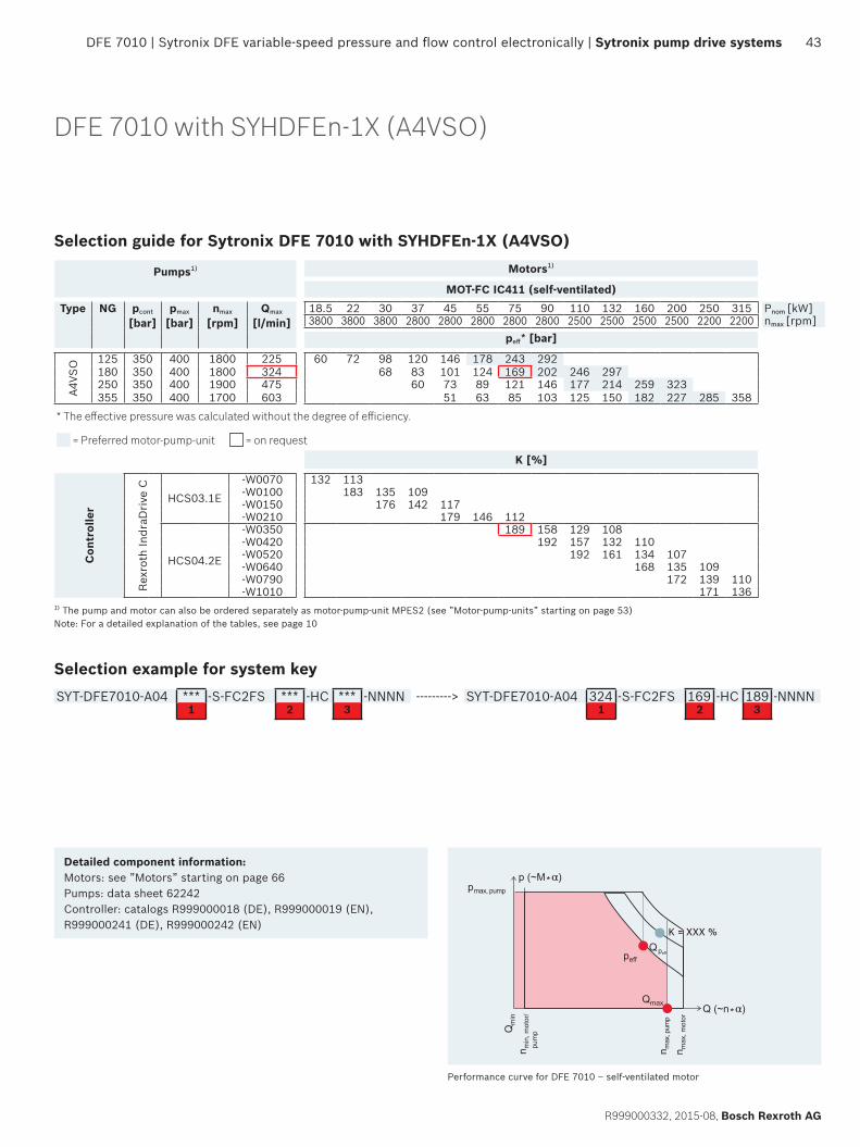
DFE 7010 | Sytronix DFE variable-speed pressure and flow control electronically | Sytronix pump drive systems 43
R999000332, 2015-08, Bosch Rexroth AG
DFE 7010 with SYHDFEn-1X (A4VSO)
Selection guide for Sytronix DFE 7010 with SYHDFEn-1X (A4VSO)
Pumps1) Motors1)
MOT-FC IC411 (self-ventilated)Type NG pcont
[bar]pmax
[bar]nmax
[rpm]Qmax
[l/min]18.5 22 30 37 45 55 75 90 110 132 160 200 250 315 Pnom [kW]3800 3800 3800 2800 2800 2800 2800 2800 2500 2500 2500 2500 2200 2200 nmax [rpm]
peff* [bar]
A4VS
O 125 350 400 1800 225 60 72 98 120 146 178 243 292180 350 400 1800 324 68 83 101 124 169 202 246 297250 350 400 1900 475 60 73 89 121 146 177 214 259 323355 350 400 1700 603 51 63 85 103 125 150 182 227 285 358
* The effective pressure was calculated without the degree of efficiency.
= Preferred motor-pump-unit = on request
K [%]
Con
trol
ler
Rexr
oth
Indr
aDri
ve C
HCS03.1E
-W0070 132 113-W0100 183 135 109-W0150 176 142 117-W0210 179 146 112
HCS04.2E
-W0350 189 158 129 108-W0420 192 157 132 110-W0520 192 161 134 107-W0640 168 135 109-W0790 172 139 110-W1010 171 136
1) The pump and motor can also be ordered separately as motor-pump-unit MPES2 (see ”Motor-pump-units” starting on page 53) Note: For a detailed explanation of the tables, see page 10
Selection example for system keySYT-DFE7010-A04 *** -S-FC2FS *** -HC *** -NNNN ---------> SYT-DFE7010-A04 324 -S-FC2FS 169 -HC 189 -NNNN
1 2 3 1 2 3
Qmax
n max
, pum
p
pmax, pump
n max
, mot
or
n min
, mot
or/
pum
pQm
in
Q (~n*α)
peffQpeff
p (~M*α)
Performance curve for DFE 7010 – self-ventilated motor
Detailed component information:Motors: see ”Motors” starting on page 66Pumps: data sheet 62242Controller: catalogs R999000018 (DE), R999000019 (EN), R999000241 (DE), R999000242 (EN)
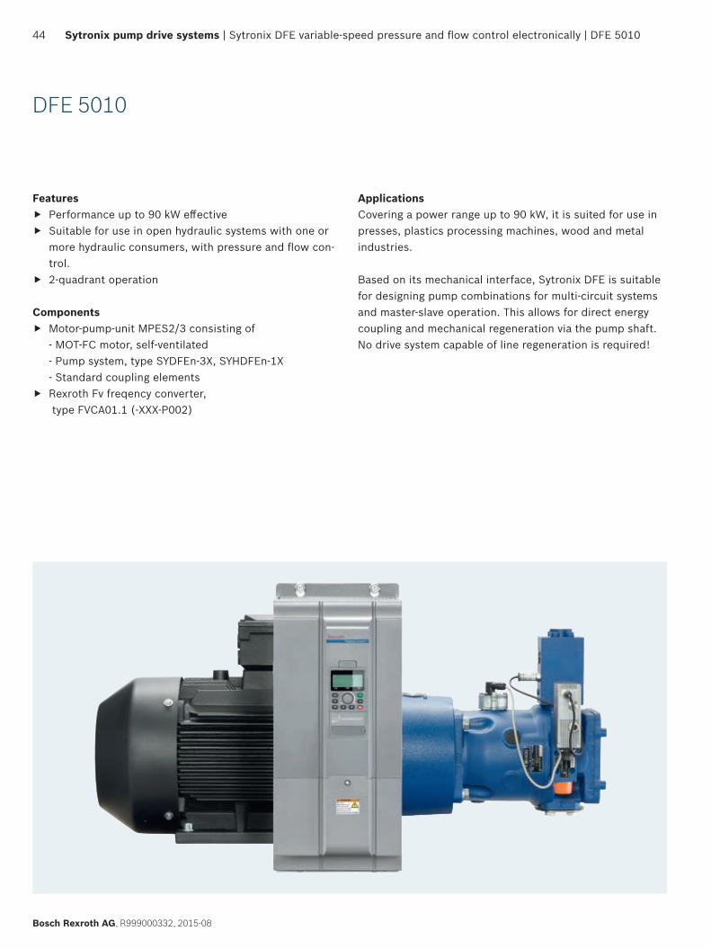
44 Sytronix pump drive systems | Sytronix DFE variable-speed pressure and flow control electronically | DFE 5010
Bosch Rexroth AG, R999000332, 2015-08
DFE 5010
Features f Performance up to 90 kW effective f Suitable for use in open hydraulic systems with one or
more hydraulic consumers, with pressure and flow con-trol.
f 2-quadrant operation
Components f Motor-pump-unit MPES2/3 consisting of
- MOT-FC motor, self-ventilated - Pump system, type SYDFEn-3X, SYHDFEn-1X - Standard coupling elements
f Rexroth Fv freqency converter, type FVCA01.1 (-XXX-P002)
ApplicationsCovering a power range up to 90 kW, it is suited for use in presses, plastics processing machines, wood and metal industries.
Based on its mechanical interface, Sytronix DFE is suitable for designing pump combinations for multi-circuit systems and master-slave operation. This allows for direct energy coupling and mechanical regeneration via the pump shaft. No drive system capable of line regeneration is required!
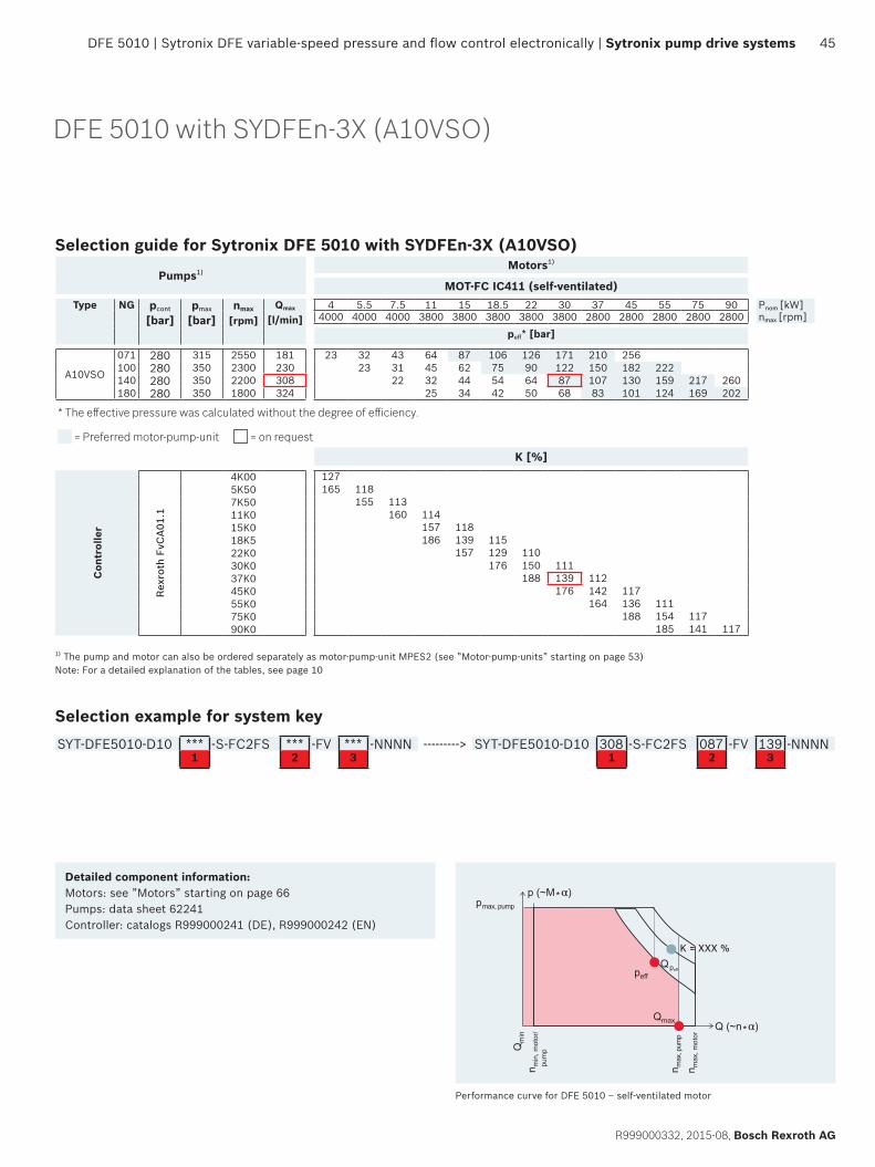
DFE 5010 | Sytronix DFE variable-speed pressure and flow control electronically | Sytronix pump drive systems 45
R999000332, 2015-08, Bosch Rexroth AG
DFE 5010 with SYDFEn-3X (A10VSO)
Selection guide for Sytronix DFE 5010 with SYDFEn-3X (A10VSO)
Pumps1) Motors1)
MOT-FC IC411 (self-ventilated)Type NG pcont
[bar]pmax
[bar]nmax
[rpm]Qmax
[l/min]4 5.5 7.5 11 15 18.5 22 30 37 45 55 75 90 Pnom [kW]
4000 4000 4000 3800 3800 3800 3800 3800 2800 2800 2800 2800 2800 nmax [rpm]peff* [bar]
A10VSO
071 280 315 2550 181 23 32 43 64 87 106 126 171 210 256100 280 350 2300 230 23 31 45 62 75 90 122 150 182 222140 280 350 2200 308 22 32 44 54 64 87 107 130 159 217 260180 280 350 1800 324 25 34 42 50 68 83 101 124 169 202
* The effective pressure was calculated without the degree of efficiency.
= Preferred motor-pump-unit = on request
K [%]
Con
trol
ler
Rex
roth
FvC
A01.
1
4K00 1275K50 165 1187K50 155 11311K0 160 11415K0 157 11818K5 186 139 11522K0 157 129 11030K0 176 150 11137K0 188 139 11245K0 176 142 11755K0 164 136 11175K0 188 154 11790K0 185 141 117
1) The pump and motor can also be ordered separately as motor-pump-unit MPES2 (see ”Motor-pump-units” starting on page 53) Note: For a detailed explanation of the tables, see page 10
Selection example for system keySYT-DFE5010-D10 *** -S-FC2FS *** -FV *** -NNNN ---------> SYT-DFE5010-D10 308 -S-FC2FS 087 -FV 139 -NNNN
1 2 3 1 2 3
Qmax
n max
, pum
p
pmax, pump
n max
, mot
or
n min
, mot
or/
pum
pQm
in
Q (~n*α)
peffQpeff
p (~M*α)
Performance curve for DFE 5010 – self-ventilated motor
Detailed component information:Motors: see ”Motors” starting on page 66Pumps: data sheet 62241Controller: catalogs R999000241 (DE), R999000242 (EN)
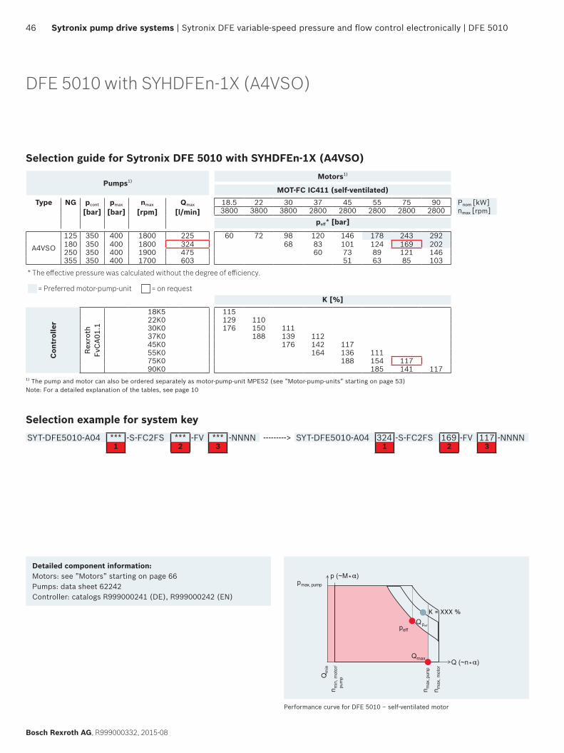
46 Sytronix pump drive systems | Sytronix DFE variable-speed pressure and flow control electronically | DFE 5010
Bosch Rexroth AG, R999000332, 2015-08
DFE 5010 with SYHDFEn-1X (A4VSO)
Selection guide for Sytronix DFE 5010 with SYHDFEn-1X (A4VSO)
Pumps1) Motors1)
MOT-FC IC411 (self-ventilated)Type NG pcont
[bar]pmax
[bar]nmax
[rpm]Qmax
[l/min]18.5 22 30 37 45 55 75 90 Pnom [kW]3800 3800 3800 2800 2800 2800 2800 2800 nmax [rpm]
peff* [bar]
A4VSO
125 350 400 1800 225 60 72 98 120 146 178 243 292180 350 400 1800 324 68 83 101 124 169 202250 350 400 1900 475 60 73 89 121 146355 350 400 1700 603 51 63 85 103
* The effective pressure was calculated without the degree of efficiency.
= Preferred motor-pump-unit = on requestK [%]
Con
trol
ler
Rex
roth
Fv
CA0
1.1
18K5 11522K0 129 11030K0 176 150 11137K0 188 139 11245K0 176 142 11755K0 164 136 11175K0 188 154 11790K0 185 141 117
1) The pump and motor can also be ordered separately as motor-pump-unit MPES2 (see ”Motor-pump-units” starting on page 53) Note: For a detailed explanation of the tables, see page 10
Selection example for system keySYT-DFE5010-A04 *** -S-FC2FS *** -FV *** -NNNN ---------> SYT-DFE5010-A04 324 -S-FC2FS 169 -FV 117 -NNNN
1 2 3 1 2 3
Detailed component information:Motors: see ”Motors” starting on page 66Pumps: data sheet 62242Controller: catalogs R999000241 (DE), R999000242 (EN)
Qmax
n max
, pum
p
pmax, pump
n max
, mot
or
n min
, mot
or/
pum
pQm
in
Q (~n*α)
peffQpeff
p (~M*α)
Performance curve for DFE 5010 – self-ventilated motor
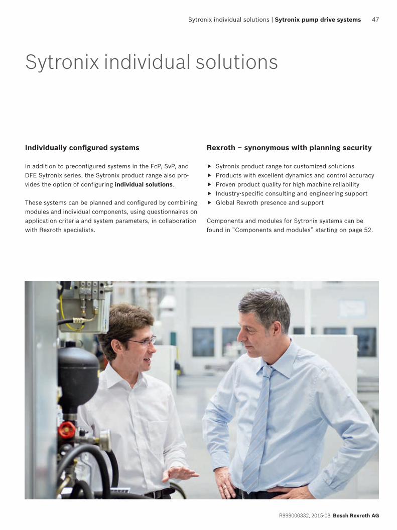
Sytronix individual solutions | Sytronix pump drive systems 47
R999000332, 2015-08, Bosch Rexroth AG
Individually configured systems
In addition to preconfigured systems in the FcP, SvP, and DFE Sytronix series, the Sytronix product range also pro-vides the option of configuring individual solutions.
These systems can be planned and configured by combining modules and individual components, using questionnaires on application criteria and system parameters, in collaboration with Rexroth specialists.
Sytronix individual solutions
Rexroth – synonymous with planning security
f Sytronix product range for customized solutions f Products with excellent dynamics and control accuracy f Proven product quality for high machine reliability f Industry-specific consulting and engineering support f Global Rexroth presence and support
Components and modules for Sytronix systems can be found in ”Components and modules” starting on page 52.
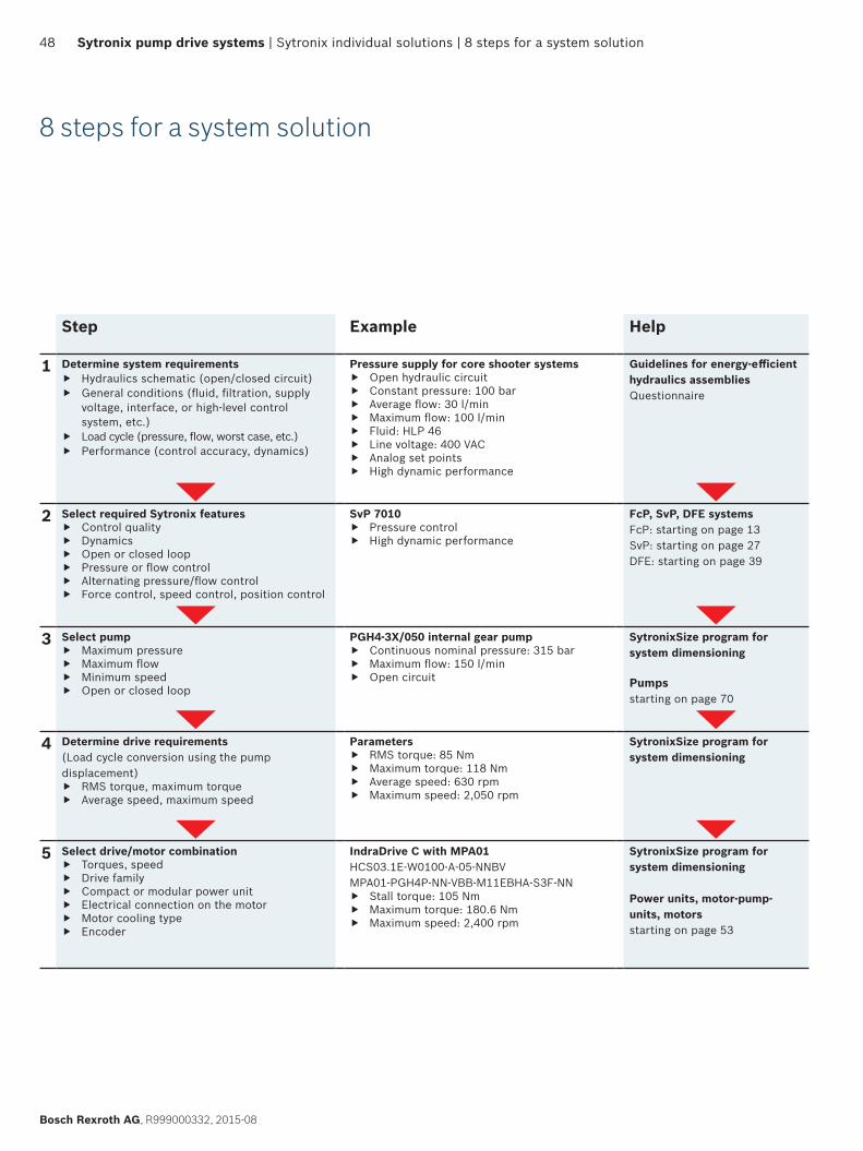
48 Sytronix pump drive systems | Sytronix individual solutions | 8 steps for a system solution
Bosch Rexroth AG, R999000332, 2015-08
8 steps for a system solution
Step Example Help
1 Determine system requirements f Hydraulics schematic (open/closed circuit) f General conditions (fluid, filtration, supply
voltage, interface, or high-level control system, etc.)
f Load cycle (pressure, flow, worst case, etc.) f Performance (control accuracy, dynamics)
Pressure supply for core shooter systems f Open hydraulic circuit f Constant pressure: 100 bar f Average flow: 30 l/min f Maximum flow: 100 l/min f Fluid: HLP 46 f Line voltage: 400 VAC f Analog set points f High dynamic performance
Guidelines for energy-efficient hydraulics assembliesQuestionnaire
2 Select required Sytronix features f Control quality f Dynamics f Open or closed loop f Pressure or flow control f Alternating pressure/flow control f Force control, speed control, position control
SvP 7010 f Pressure control f High dynamic performance
FcP, SvP, DFE systemsFcP: starting on page 13SvP: starting on page 27DFE: starting on page 39
3 Select pump f Maximum pressure f Maximum flow f Minimum speed f Open or closed loop
PGH4-3X/050 internal gear pump f Continuous nominal pressure: 315 bar f Maximum flow: 150 l/min f Open circuit
SytronixSize program for system dimensioning
Pumpsstarting on page 70
4 Determine drive requirements(Load cycle conversion using the pump displacement)
f RMS torque, maximum torque f Average speed, maximum speed
Parameters f RMS torque: 85 Nm f Maximum torque: 118 Nm f Average speed: 630 rpm f Maximum speed: 2,050 rpm
SytronixSize program for system dimensioning
5 Select drive/motor combination f Torques, speed f Drive family f Compact or modular power unit f Electrical connection on the motor f Motor cooling type f Encoder
IndraDrive C with MPA01 HCS03.1E-W0100-A-05-NNBVMPA01-PGH4P-NN-VBB-M11EBHA-S3F-NN
f Stall torque: 105 Nm f Maximum torque: 180.6 Nm f Maximum speed: 2,400 rpm
SytronixSize program for system dimensioning
Power units, motor-pump-units, motorsstarting on page 53
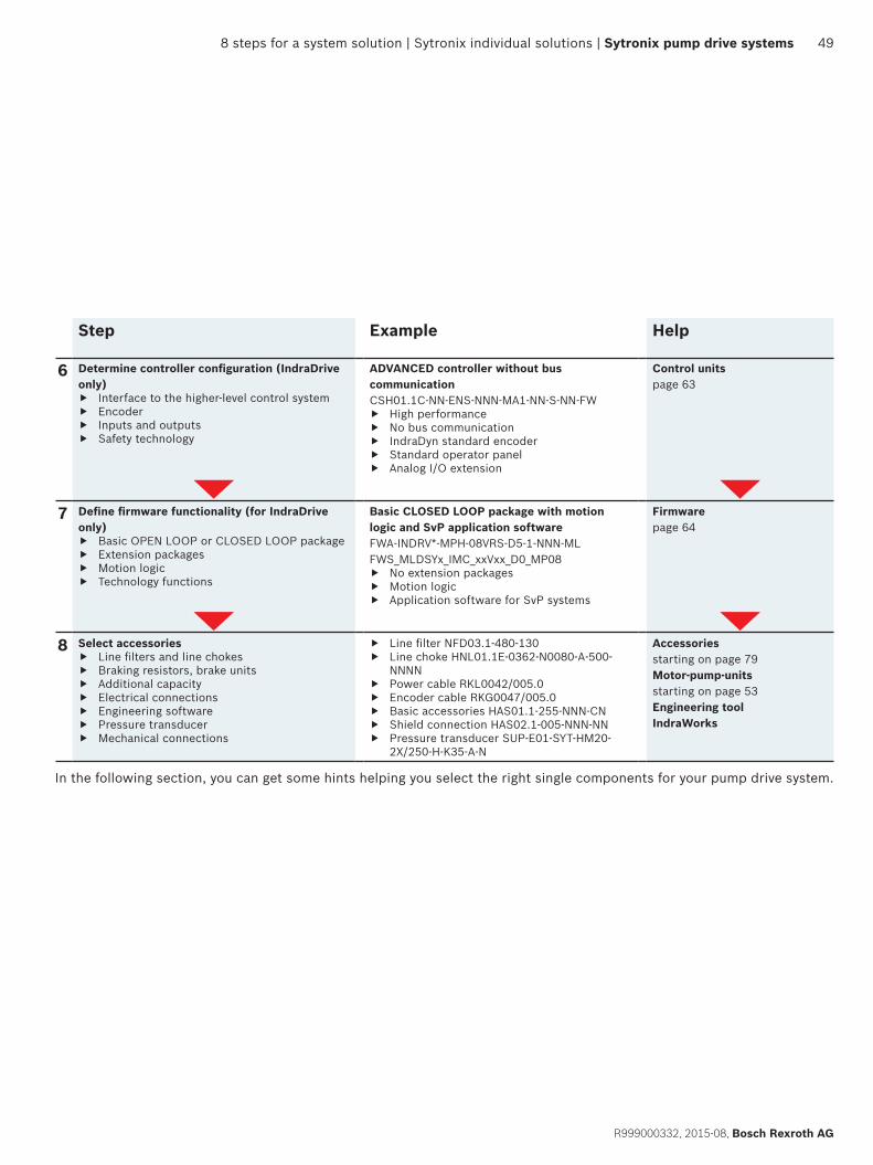
8 steps for a system solution | Sytronix individual solutions | Sytronix pump drive systems 49
R999000332, 2015-08, Bosch Rexroth AG
Step Example Help
6 Determine controller configuration (IndraDrive only)
f Interface to the higher-level control system f Encoder f Inputs and outputs f Safety technology
ADVANCED controller without bus communicationCSH01.1C-NN-ENS-NNN-MA1-NN-S-NN-FW
f High performance f No bus communication f IndraDyn standard encoder f Standard operator panel f Analog I/O extension
Control unitspage 63
7 Define firmware functionality (for IndraDrive only)
f Basic OPEN LOOP or CLOSED LOOP package f Extension packages f Motion logic f Technology functions
Basic CLOSED LOOP package with motion logic and SvP application softwareFWA-INDRV*-MPH-08VRS-D5-1-NNN-MLFWS_MLDSYx_IMC_xxVxx_D0_MP08
f No extension packages f Motion logic f Application software for SvP systems
Firmwarepage 64
8 Select accessories f Line filters and line chokes f Braking resistors, brake units f Additional capacity f Electrical connections f Engineering software f Pressure transducer f Mechanical connections
f Line filter NFD03.1-480-130 f Line choke HNL01.1E-0362-N0080-A-500-
NNNN f Power cable RKL0042/005.0 f Encoder cable RKG0047/005.0 f Basic accessories HAS01.1-255-NNN-CN f Shield connection HAS02.1-005-NNN-NN f Pressure transducer SUP-E01-SYT-HM20-
2X/250-H-K35-A-N
Accessoriesstarting on page 79 Motor-pump-unitsstarting on page 53Engineering tool IndraWorks
In the following section, you can get some hints helping you select the right single components for your pump drive system.
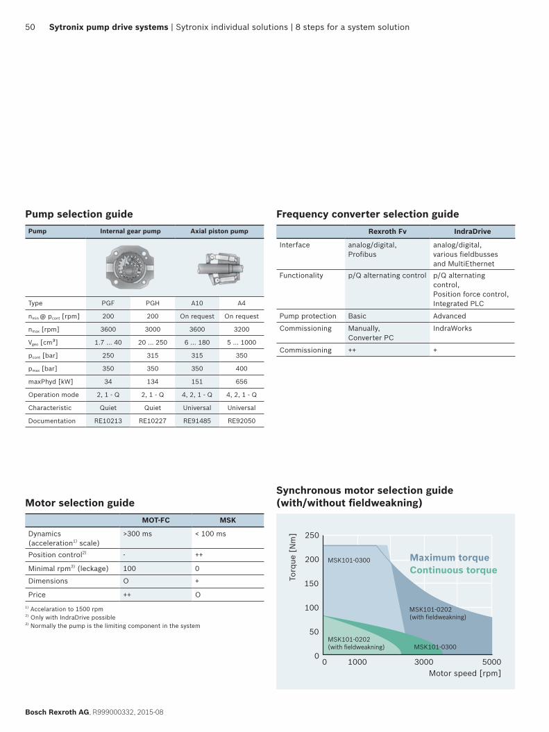
50 Sytronix pump drive systems | Sytronix individual solutions | 8 steps for a system solution
Bosch Rexroth AG, R999000332, 2015-08
Frequency converter selection guideRexroth Fv IndraDrive
Interface analog/digital, Profibus
analog/digital,various fieldbusses and MultiEthernet
Functionality p/Q alternating control p/Q alternating control, Position force control, Integrated PLC
Pump protection Basic Advanced
Commissioning Manually,Converter PC
IndraWorks
Commissioning ++ +
Motor selection guideMOT-FC MSK
Dynamics (acceleration1) scale)
>300 ms < 100 ms
Position control2) - ++
Minimal rpm3) (leckage) 100 0
Dimensions O +
Price ++ O1) Accelaration to 1500 rpm 2) Only with IndraDrive possible 3) Normally the pump is the limiting component in the system
Synchronous motor selection guide (with/without fieldweakning)
Torq
ue [
Nm
]
Motor speed [rpm]0 50001000
50
100
150
200
250
03000
MSK101-0300MSK101-0202(with fi eldweakning)
MSK101-0202(with fi eldweakning)
MSK101-0300 Maximum torqueContinuous torque
Pump selection guidePump Internal gear pump Axial piston pump
Type PGF PGH A10 A4
nmin @ pcont [rpm] 200 200 On request On request
nmax [rpm] 3600 3000 3600 3200
Vgeo [cm³] 1.7 … 40 20 … 250 6 … 180 5 … 1000
pcont [bar] 250 315 315 350
pmax [bar] 350 350 350 400
maxPhyd [kW] 34 134 151 656
Operation mode 2, 1 - Q 2, 1 - Q 4, 2, 1 - Q 4, 2, 1 - Q
Characteristic Quiet Quiet Universal Universal
Documentation RE10213 RE10227 RE91485 RE92050
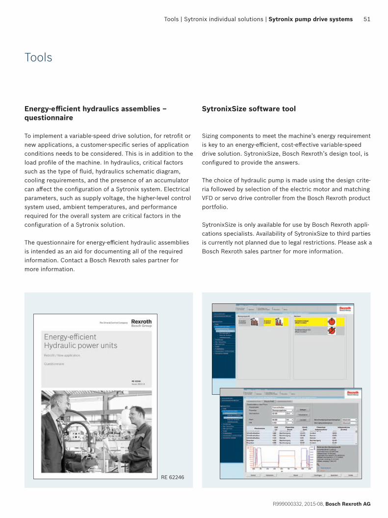
Tools | Sytronix individual solutions | Sytronix pump drive systems 51
R999000332, 2015-08, Bosch Rexroth AG
Energy-efficient hydraulics assemblies – questionnaire
To implement a variable-speed drive solution, for retrofit or new applications, a customer-specific series of application conditions needs to be considered. This is in addition to the load profile of the machine. In hydraulics, critical factors such as the type of fluid, hydraulics schematic diagram, cooling requirements, and the presence of an accumulator can affect the configuration of a Sytronix system. Electrical parameters, such as supply voltage, the higher-level control system used, ambient temperatures, and performance required for the overall system are critical factors in the configuration of a Sytronix solution.
The questionnaire for energy-efficient hydraulic assemblies is intended as an aid for documenting all of the required information. Contact a Bosch Rexroth sales partner for more information.
Tools
SytronixSize software tool
Sizing components to meet the machine’s energy requirement is key to an energy-efficient, cost-effective variable-speed drive solution. SytronixSize, Bosch Rexroth’s design tool, is configured to provide the answers.
The choice of hydraulic pump is made using the design crite-ria followed by selection of the electric motor and matching VFD or servo drive controller from the Bosch Rexroth product portfolio.
SytronixSize is only available for use by Bosch Rexroth appli-cations specialists. Availability of SytronixSize to third parties is currently not planned due to legal restrictions. Please ask a Bosch Rexroth sales partner for more information.
RE 62246
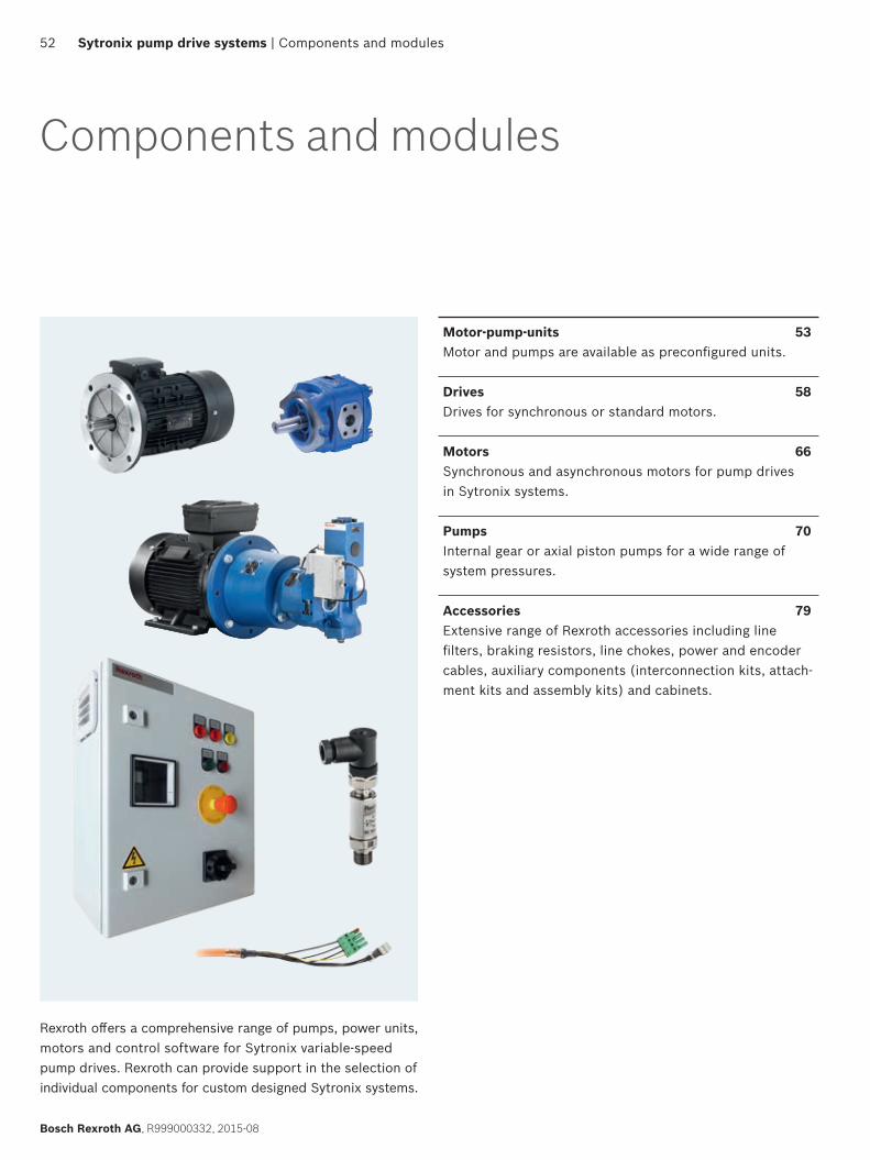
52
Bosch Rexroth AG, R999000332, 2015-08
Sytronix pump drive systems | Components and modules
Components and modules
Motor-pump-units 53Motor and pumps are available as preconfigured units.
Drives 58Drives for synchronous or standard motors.
Motors 66Synchronous and asynchronous motors for pump drives in Sytronix systems.
Pumps 70Internal gear or axial piston pumps for a wide range of system pressures.
Accessories 79Extensive range of Rexroth accessories including line filters, braking resistors, line chokes, power and encoder cables, auxiliary components (interconnection kits, attach-ment kits and assembly kits) and cabinets.
Rexroth offers a comprehensive range of pumps, power units, motors and control software for Sytronix variable-speed pump drives. Rexroth can provide support in the selection of individual components for custom designed Sytronix systems.
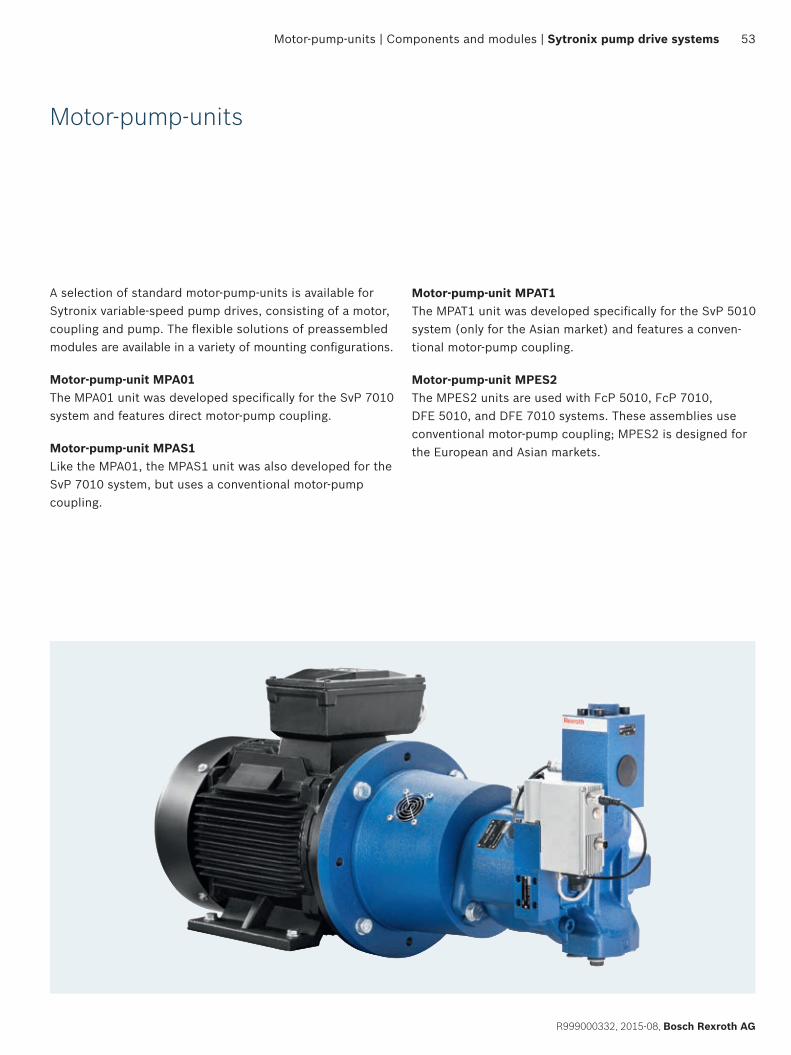
53
R999000332, 2015-08, Bosch Rexroth AG
Motor-pump-units | Components and modules | Sytronix pump drive systems
Motor-pump-units
A selection of standard motor-pump-units is available for Sytronix variable-speed pump drives, consisting of a motor, coupling and pump. The flexible solutions of preassembled modules are available in a variety of mounting configurations.
Motor-pump-unit MPA01The MPA01 unit was developed specifically for the SvP 7010 system and features direct motor-pump coupling.
Motor-pump-unit MPAS1Like the MPA01, the MPAS1 unit was also developed for the SvP 7010 system, but uses a conventional motor-pump coupling.
Motor-pump-unit MPAT1The MPAT1 unit was developed specifically for the SvP 5010 system (only for the Asian market) and features a conven-tional motor-pump coupling.
Motor-pump-unit MPES2The MPES2 units are used with FcP 5010, FcP 7010, DFE 5010, and DFE 7010 systems. These assemblies use conventional motor-pump coupling; MPES2 is designed for the European and Asian markets.
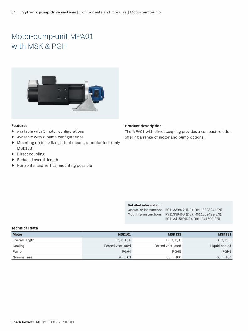
54
Bosch Rexroth AG, R999000332, 2015-08
Sytronix pump drive systems | Components and modules | Motor-pump-units
Motor-pump-unit MPA01 with MSK & PGH
Features f Available with 3 motor configurations f Available with 8 pump configurations f Mounting options: flange, foot mount, or motor feet (only
MSK133) f Direct coupling f Reduced overall length f Horizontal and vertical mounting possible
Product descriptionThe MPA01 with direct coupling provides a compact solution, offering a range of motor and pump options.
Detailed information:Operating instructions: R911339822 (DE), R911339824 (EN)Mounting instructions: R911339498 (DE), R911339499(EN),
R911341599(DE), R911341600(EN)
Technical dataMotor MSK101 MSK133 MSK133
Overall length C, D, E, F B, C, D, E B, C, D, E
Cooling Forced-ventilated Forced-ventilated Liquid-cooled
Pump PGH4 PGH5 PGH5
Nominal size 20 … 63 63 … 160 63 … 160
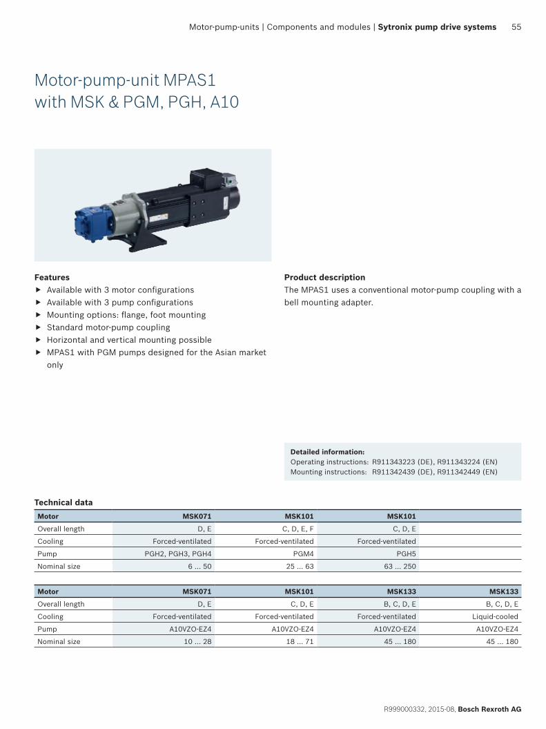
55
R999000332, 2015-08, Bosch Rexroth AG
Motor-pump-units | Components and modules | Sytronix pump drive systems
Motor-pump-unit MPAS1 with MSK & PGM, PGH, A10
Features f Available with 3 motor configurations f Available with 3 pump configurations f Mounting options: flange, foot mounting f Standard motor-pump coupling f Horizontal and vertical mounting possible f MPAS1 with PGM pumps designed for the Asian market
only
Product descriptionThe MPAS1 uses a conventional motor-pump coupling with a bell mounting adapter.
Detailed information:Operating instructions: R911343223 (DE), R911343224 (EN)Mounting instructions: R911342439 (DE), R911342449 (EN)
Technical dataMotor MSK071 MSK101 MSK101
Overall length D, E C, D, E, F C, D, E
Cooling Forced-ventilated Forced-ventilated Forced-ventilated
Pump PGH2, PGH3, PGH4 PGM4 PGH5
Nominal size 6 … 50 25 … 63 63 … 250
Motor MSK071 MSK101 MSK133 MSK133
Overall length D, E C, D, E B, C, D, E B, C, D, E
Cooling Forced-ventilated Forced-ventilated Forced-ventilated Liquid-cooled
Pump A10VZO-EZ4 A10VZO-EZ4 A10VZO-EZ4 A10VZO-EZ4
Nominal size 10 … 28 18 … 71 45 … 180 45 … 180
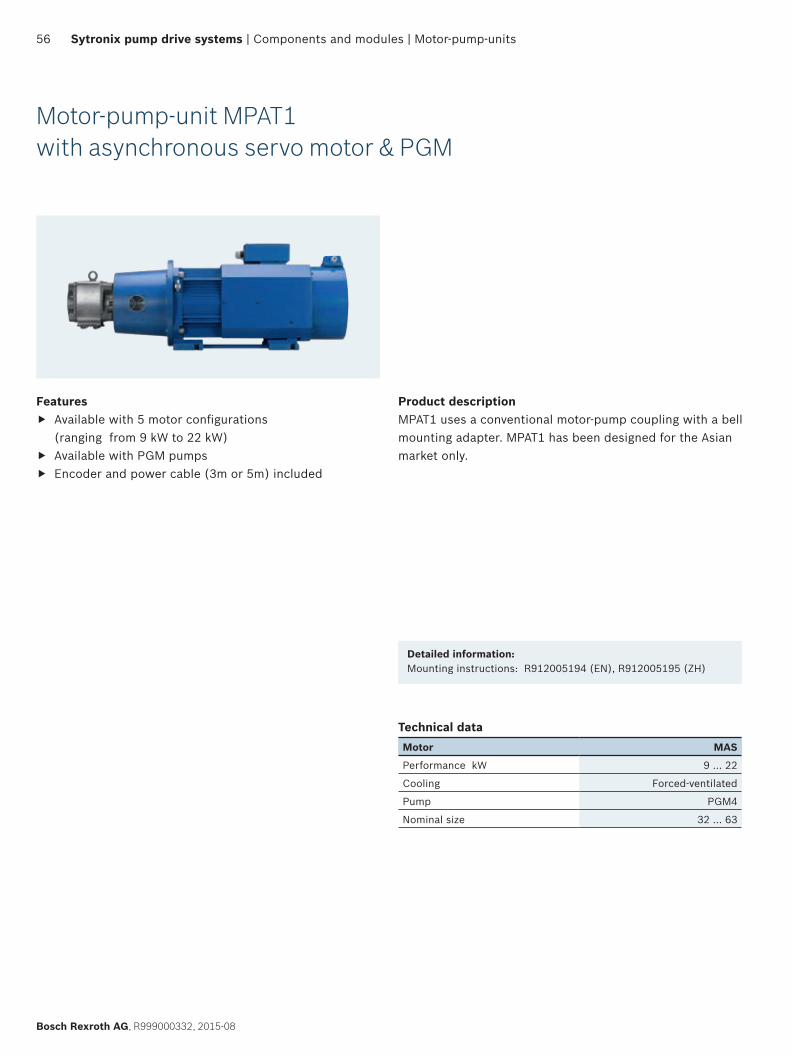
56
Bosch Rexroth AG, R999000332, 2015-08
Sytronix pump drive systems | Components and modules | Motor-pump-units
Motor-pump-unit MPAT1 with asynchronous servo motor & PGM
Features f Available with 5 motor configurations
(ranging from 9 kW to 22 kW) f Available with PGM pumps f Encoder and power cable (3m or 5m) included
Product descriptionMPAT1 uses a conventional motor-pump coupling with a bell mounting adapter. MPAT1 has been designed for the Asian market only.
Detailed information:Mounting instructions: R912005194 (EN), R912005195 (ZH)
Technical dataMotor MAS
Performance kW 9 … 22
Cooling Forced-ventilated
Pump PGM4
Nominal size 32 … 63
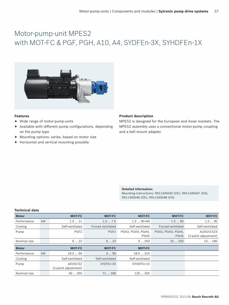
57
R999000332, 2015-08, Bosch Rexroth AG
Motor-pump-units | Components and modules | Sytronix pump drive systems
Motor-pump-unit MPES2 with MOT-FC & PGF, PGH, A10, A4, SYDFEn-3X, SYHDFEn-1X
Features f Wide range of motor-pump-units f Available with different pump configurations, depending
on the pump type f Mounting options: varies, based on motor size f Horizontal and vertical mounting possible
Product descriptionMPES2 is designed for the European and Asian markets. The MPES2 assembly uses a conventional motor-pump coupling and a bell mount adapter.
Technical dataMotor MOT-FC MOT-FC MOT-FC MOT-FC MOT-FC
Performance kW 1.5 … 11 1.5 … 7.5 1.5 … 90 kW 1.5 … 90 1.5 … 90
Cooling Self-ventilated Forced ventilated Self-ventilated Forced-ventilated Self-ventilated
Pump PGF2 PGF2 PGH2, PGH3, PGH4, PGH5
PGH2, PGH3, PGH4, PGH5
A10VZO-EZ4(2-point adjustment)
Nominal size 6 … 22 6 … 22 5 … 250 25 … 250 10 … 180
Motor MOT-FC MOT-FC MOT-FC
Performance kW 18.5 … 90 4 … 90 18.5 … 315
Cooling Self-ventilated Self-ventilated Self-ventilated
Pump A4VSO-EZ(2-point adjustment)
SYDFEn-3X SYHDFEn-1X
Nominal size 40 … 355 71 … 180 125 … 355
Detailed information:Mounting instructions: R911345045 (DE), R911345047 (EN), R911345046 (DE), R911345048 (EN)
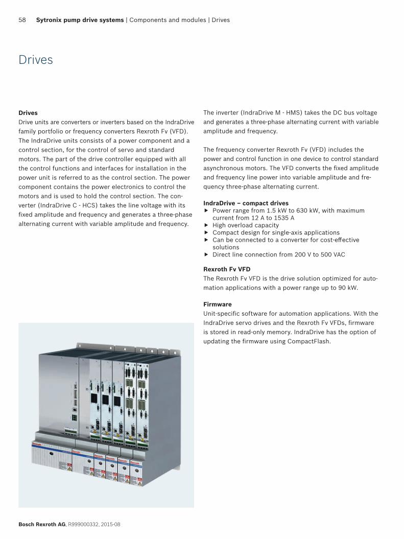
58
Bosch Rexroth AG, R999000332, 2015-08
Sytronix pump drive systems | Components and modules | Drives
Drives
DrivesDrive units are converters or inverters based on the IndraDrive family portfolio or frequency converters Rexroth Fv (VFD). The IndraDrive units consists of a power component and a control section, for the control of servo and standard motors. The part of the drive controller equipped with all the control functions and interfaces for installation in the power unit is referred to as the control section. The power component contains the power electronics to control the motors and is used to hold the control section. The con-verter (IndraDrive C - HCS) takes the line voltage with its fixed amplitude and frequency and generates a three-phase alternating current with variable amplitude and frequency.
The inverter (IndraDrive M - HMS) takes the DC bus voltage and generates a three-phase alternating current with variable amplitude and frequency.
The frequency converter Rexroth Fv (VFD) includes the power and control function in one device to control standard asynchronous motors. The VFD converts the fixed amplitude and frequency line power into variable amplitude and fre-quency three-phase alternating current.
IndraDrive – compact drives f Power range from 1.5 kW to 630 kW, with maximum
current from 12 A to 1535 A f High overload capacity f Compact design for single-axis applications f Can be connected to a converter for cost-effective
solutions f Direct line connection from 200 V to 500 VAC
Rexroth Fv VFDThe Rexroth Fv VFD is the drive solution optimized for auto-mation applications with a power range up to 90 kW.
FirmwareUnit-specific software for automation applications. With the IndraDrive servo drives and the Rexroth Fv VFDs, firmware is stored in read-only memory. IndraDrive has the option of updating the firmware using CompactFlash.
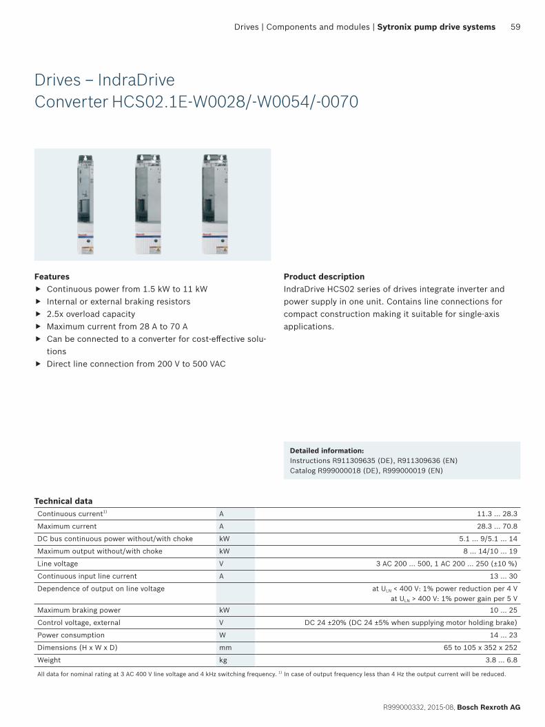
59
R999000332, 2015-08, Bosch Rexroth AG
Drives | Components and modules | Sytronix pump drive systems
Drives – IndraDrive Converter HCS02.1E-W0028/-W0054/-0070
Features f Continuous power from 1.5 kW to 11 kW f Internal or external braking resistors f 2.5x overload capacity f Maximum current from 28 A to 70 A f Can be connected to a converter for cost-effective solu-
tions f Direct line connection from 200 V to 500 VAC
Product descriptionIndraDrive HCS02 series of drives integrate inverter and power supply in one unit. Contains line connections for compact construction making it suitable for single-axis applications.
Detailed information:Instructions R911309635 (DE), R911309636 (EN)Catalog R999000018 (DE), R999000019 (EN)
Technical dataContinuous current1) A 11.3 … 28.3
Maximum current A 28.3 … 70.8
DC bus continuous power without/with choke kW 5.1 … 9/5.1 … 14
Maximum output without/with choke kW 8 … 14/10 … 19
Line voltage V 3 AC 200 … 500, 1 AC 200 … 250 (±10 %)
Continuous input line current A 13 … 30
Dependence of output on line voltage at ULN < 400 V: 1% power reduction per 4 Vat ULN > 400 V: 1% power gain per 5 V
Maximum braking power kW 10 … 25
Control voltage, external V DC 24 ±20% (DC 24 ±5% when supplying motor holding brake)
Power consumption W 14 … 23
Dimensions (H x W x D) mm 65 to 105 x 352 x 252
Weight kg 3.8 … 6.8
All data for nominal rating at 3 AC 400 V line voltage and 4 kHz switching frequency. 1) In case of output frequency less than 4 Hz the output current will be reduced.
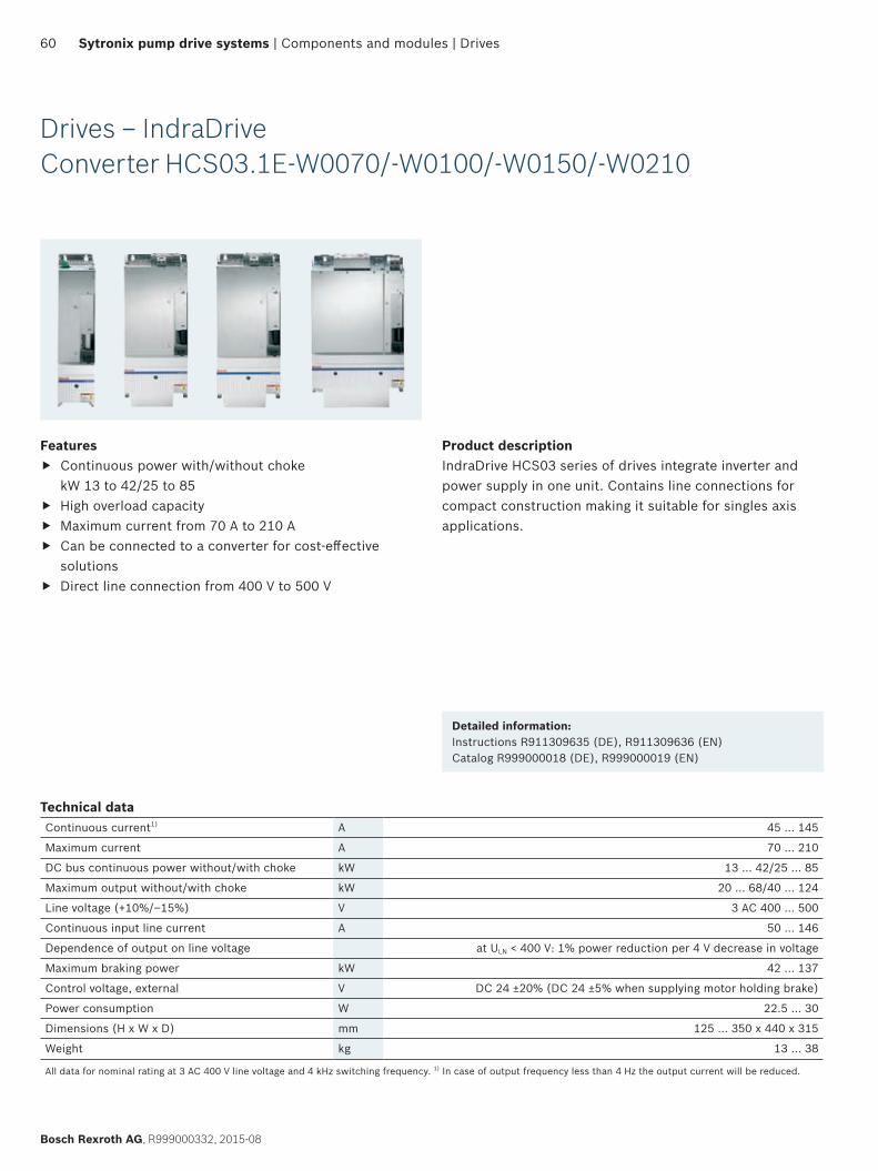
60
Bosch Rexroth AG, R999000332, 2015-08
Sytronix pump drive systems | Components and modules | Drives
Drives – IndraDriveConverter HCS03.1E-W0070/-W0100/-W0150/-W0210
Features f Continuous power with/without choke
kW 13 to 42/25 to 85 f High overload capacity f Maximum current from 70 A to 210 A f Can be connected to a converter for cost-effective
solutions f Direct line connection from 400 V to 500 V
Product descriptionIndraDrive HCS03 series of drives integrate inverter and power supply in one unit. Contains line connections for compact construction making it suitable for singles axis applications.
Detailed information:Instructions R911309635 (DE), R911309636 (EN)Catalog R999000018 (DE), R999000019 (EN)
Technical dataContinuous current1) A 45 … 145
Maximum current A 70 … 210
DC bus continuous power without/with choke kW 13 … 42/25 … 85
Maximum output without/with choke kW 20 … 68/40 … 124
Line voltage (+10%/–15%) V 3 AC 400 … 500
Continuous input line current A 50 … 146
Dependence of output on line voltage at ULN < 400 V: 1% power reduction per 4 V decrease in voltage
Maximum braking power kW 42 … 137
Control voltage, external V DC 24 ±20% (DC 24 ±5% when supplying motor holding brake)
Power consumption W 22.5 … 30
Dimensions (H x W x D) mm 125 … 350 x 440 x 315
Weight kg 13 … 38
All data for nominal rating at 3 AC 400 V line voltage and 4 kHz switching frequency. 1) In case of output frequency less than 4 Hz the output current will be reduced.
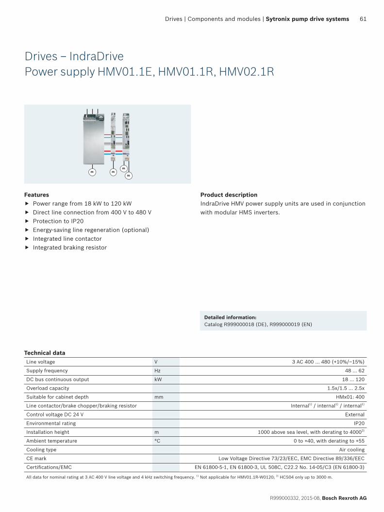
61
R999000332, 2015-08, Bosch Rexroth AG
Drives | Components and modules | Sytronix pump drive systems
Drives – IndraDrivePower supply HMV01.1E, HMV01.1R, HMV02.1R
Features f Power range from 18 kW to 120 kW f Direct line connection from 400 V to 480 V f Protection to IP20 f Energy-saving line regeneration (optional) f Integrated line contactor f Integrated braking resistor
Product descriptionIndraDrive HMV power supply units are used in conjunction with modular HMS inverters.
Technical dataLine voltage V 3 AC 400 … 480 (+10%/–15%)
Supply frequency Hz 48 … 62
DC bus continuous output kW 18 … 120
Overload capacity 1.5x/1.5 … 2.5x
Suitable for cabinet depth mm HMx01: 400
Line contactor/brake chopper/braking resistor Internal1) / internal1) / internal1)
Control voltage DC 24 V External
Environmental rating IP20
Installation height m 1000 above sea level, with derating to 40002)
Ambient temperature °C 0 to +40, with derating to +55
Cooling type Air cooling
CE mark Low Voltage Directive 73/23/EEC, EMC Directive 89/336/EEC
Certifications/EMC EN 61800-5-1, EN 61800-3, UL 508C, C22.2 No. 14-05/C3 (EN 61800-3)
All data for nominal rating at 3 AC 400 V line voltage and 4 kHz switching frequency. 1) Not applicable for HMV01.1R-W0120; 2) HCS04 only up to 3000 m.
Detailed information:Catalog R999000018 (DE), R999000019 (EN)
m
mm m
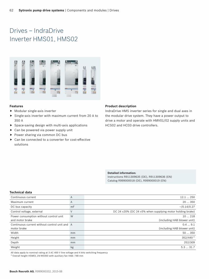
62
Bosch Rexroth AG, R999000332, 2015-08
Sytronix pump drive systems | Components and modules | Drives
Drives – IndraDriveInverter HMS01, HMS02
Features f Modular single-axis inverter f Single-axis inverter with maximum current from 20 A to
350 A f Space-saving design with multi-axis applications f Can be powered via power supply unit f Power sharing via common DC bus f Can be connected to a converter for cost-effective
solutions
Product descriptionIndraDrive HMS inverter series for single and dual axes in the modular drive system. They have a power output to drive a motor and operate with HMV01/02 supply units and HCS02 and HC03 drive controllers.
Detailed information:Instructions R911309635 (DE), R911309636 (EN)Catalog R999000018 (DE), R999000019 (EN)
Technical dataContinuous current A 12.1 … 250
Maximum current A 20 … 350
DC bus capacity mF –/0.14/0.27
Control voltage, external V DC 24 ±20% (DC 24 ±5% when supplying motor holding brake)
Power consumption without control unit and motor brake
W 10 … 218(including HAB blower unit)
Continuous current without control unit and motor brake
A 0.4 … 9.1(including HAB blower unit)
Width mm 50 … 350
Height mm 352/440 1)
Depth mm 252/309
Weight kg 5.3 … 31.7
All data apply to nominal rating at 3 AC 400 V line voltage and 4 kHz switching frequency 1) Overall height HSM01.1N-W0350 with auxiliary fan HAB: 748 mm
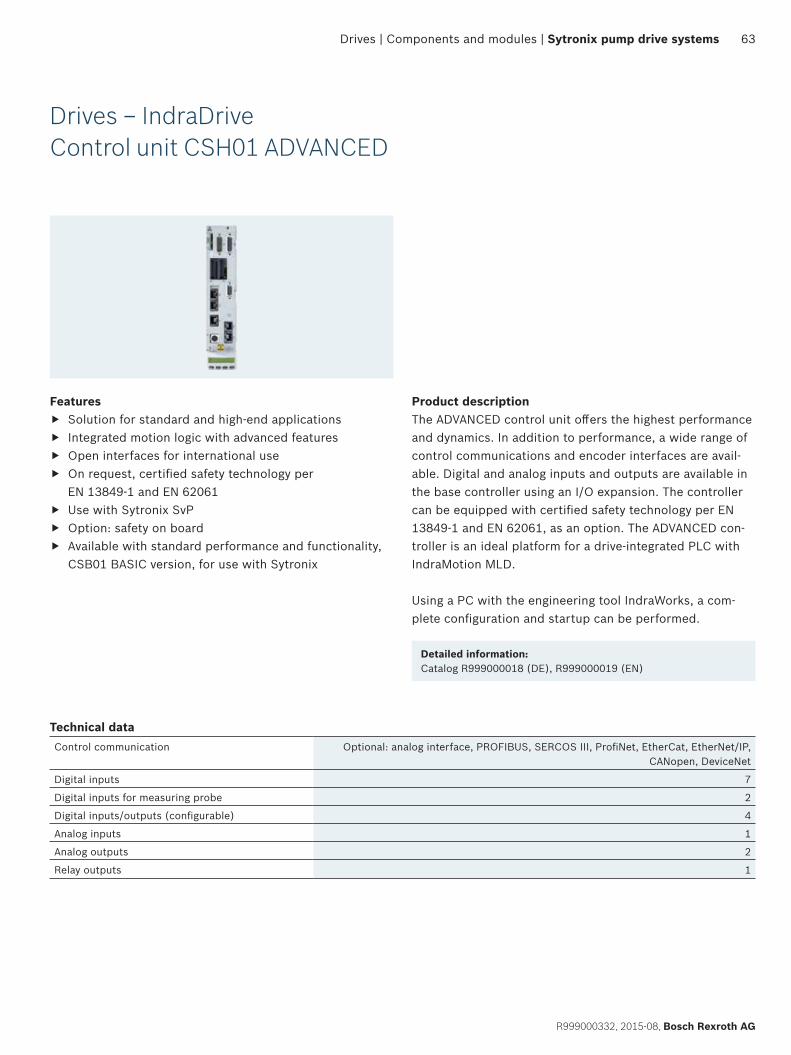
63
R999000332, 2015-08, Bosch Rexroth AG
Drives | Components and modules | Sytronix pump drive systems
Drives – IndraDriveControl unit CSH01 ADVANCED
Features f Solution for standard and high-end applications f Integrated motion logic with advanced features f Open interfaces for international use f On request, certified safety technology per
EN 13849-1 and EN 62061 f Use with Sytronix SvP f Option: safety on board f Available with standard performance and functionality,
CSB01 BASIC version, for use with Sytronix
Product descriptionThe ADVANCED control unit offers the highest performance and dynamics. In addition to performance, a wide range of control communications and encoder interfaces are avail-able. Digital and analog inputs and outputs are available in the base controller using an I/O expansion. The controller can be equipped with certified safety technology per EN 13849-1 and EN 62061, as an option. The ADVANCED con-troller is an ideal platform for a drive-integrated PLC with IndraMotion MLD.
Using a PC with the engineering tool IndraWorks, a com-plete configuration and startup can be performed.
Detailed information:Catalog R999000018 (DE), R999000019 (EN)
Technical dataControl communication Optional: analog interface, PROFIBUS, SERCOS III, ProfiNet, EtherCat, EtherNet/IP,
CANopen, DeviceNet
Digital inputs 7
Digital inputs for measuring probe 2
Digital inputs/outputs (configurable) 4
Analog inputs 1
Analog outputs 2
Relay outputs 1
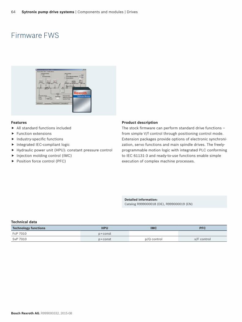
64
Bosch Rexroth AG, R999000332, 2015-08
Sytronix pump drive systems | Components and modules | Drives
Firmware FWS
Features f All standard functions included f Function extensions f Industry-specific functions f Integrated IEC-compliant logic f Hydraulic power unit (HPU): constant pressure control f Injection molding control (IMC) f Position force control (PFC)
Product descriptionThe stock firmware can perform standard drive functions – from simple V/f control through positioning control mode. Extension packages provide options of electronic synchroni-zation, servo functions and main spindle drives. The freely- programmable motion logic with integrated PLC conforming to IEC 61131-3 and ready-to-use functions enable simple execution of complex machine processes.
Detailed information:Catalog R999000018 (DE), R999000019 (EN)
Technical dataTechnology functions HPU IMC PFC
FcP 7010 p = const
SvP 7010 p = const p/Q control x/F control
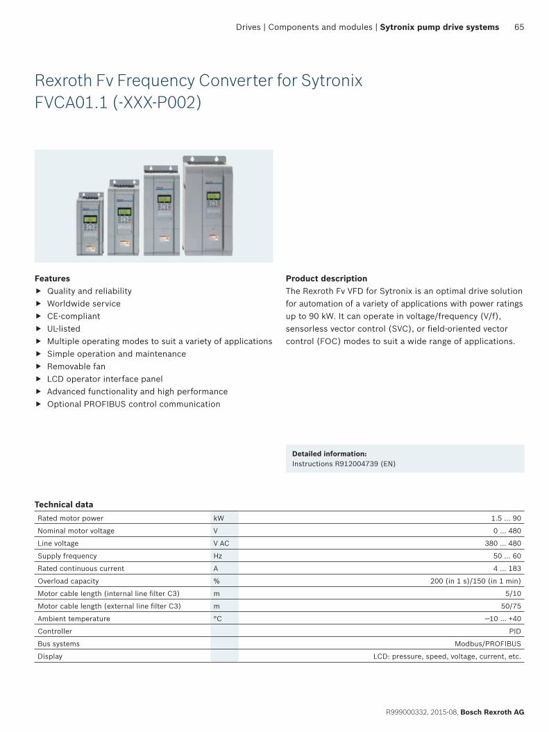
65
R999000332, 2015-08, Bosch Rexroth AG
Drives | Components and modules | Sytronix pump drive systems
Rexroth Fv Frequency Converter for SytronixFVCA01.1 (-XXX-P002)
Product descriptionThe Rexroth Fv VFD for Sytronix is an optimal drive solution for automation of a variety of applications with power ratings up to 90 kW. It can operate in voltage/frequency (V/f), sensorless vector control (SVC), or field-oriented vector control (FOC) modes to suit a wide range of applications.
Detailed information:Instructions R912004739 (EN)
Features f Quality and reliability f Worldwide service f CE-compliant f UL-listed f Multiple operating modes to suit a variety of applications f Simple operation and maintenance f Removable fan f LCD operator interface panel f Advanced functionality and high performance f Optional PROFIBUS control communication
Technical dataRated motor power kW 1.5 … 90
Nominal motor voltage V 0 … 480
Line voltage V AC 380 … 480
Supply frequency Hz 50 … 60
Rated continuous current A 4 … 183
Overload capacity % 200 (in 1 s)/150 (in 1 min)
Motor cable length (internal line filter C3) m 5/10
Motor cable length (external line filter C3) m 50/75
Ambient temperature °C —10 … +40
Controller PID
Bus systems Modbus/PROFIBUS
Display LCD: pressure, speed, voltage, current, etc.
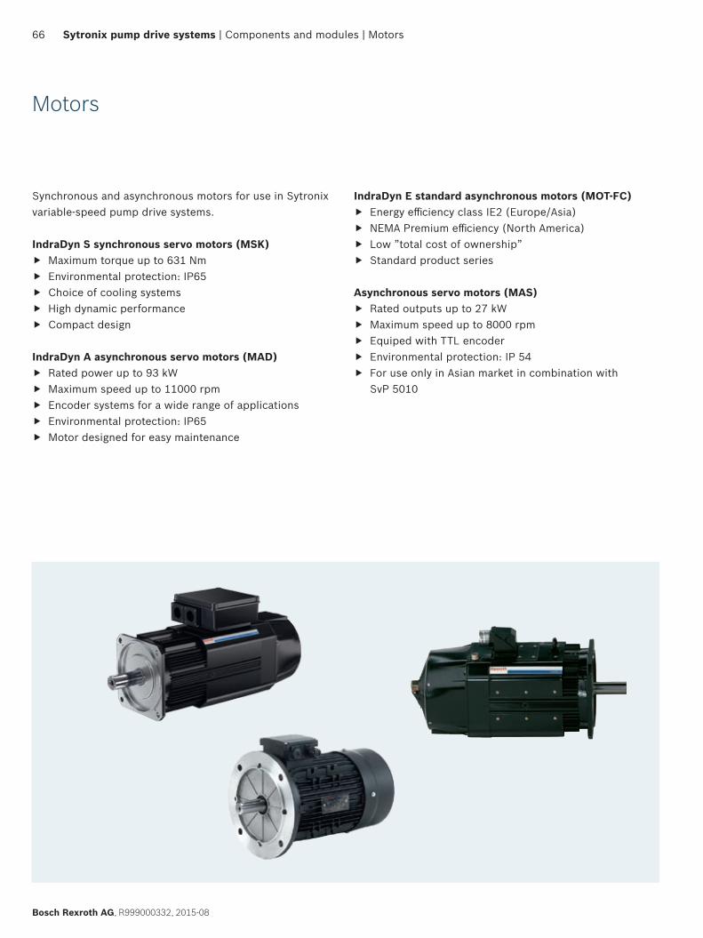
66
Bosch Rexroth AG, R999000332, 2015-08
Sytronix pump drive systems | Components and modules | Motors
Motors
Synchronous and asynchronous motors for use in Sytronix variable-speed pump drive systems.
IndraDyn S synchronous servo motors (MSK) f Maximum torque up to 631 Nm f Environmental protection: IP65 f Choice of cooling systems f High dynamic performance f Compact design
IndraDyn A asynchronous servo motors (MAD) f Rated power up to 93 kW f Maximum speed up to 11000 rpm f Encoder systems for a wide range of applications f Environmental protection: IP65 f Motor designed for easy maintenance
IndraDyn E standard asynchronous motors (MOT-FC) f Energy efficiency class IE2 (Europe/Asia) f NEMA Premium efficiency (North America) f Low ”total cost of ownership” f Standard product series
Asynchronous servo motors (MAS) f Rated outputs up to 27 kW f Maximum speed up to 8000 rpm f Equiped with TTL encoder f Environmental protection: IP 54 f For use only in Asian market in combination with
SvP 5010
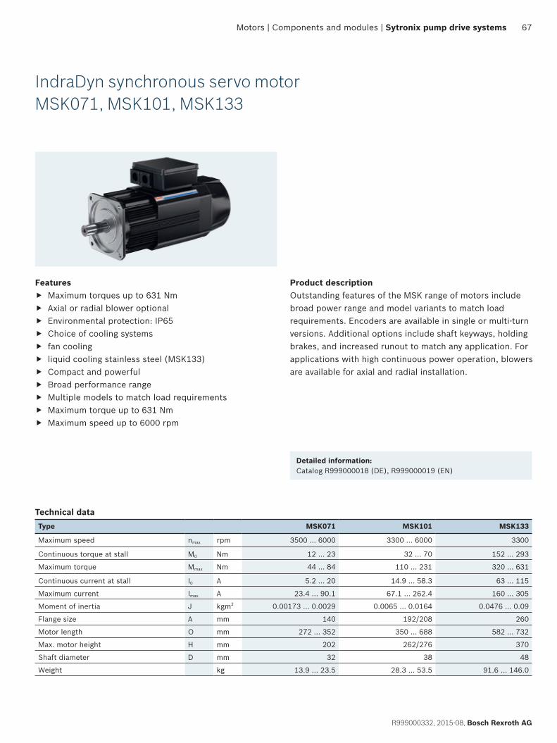
67
R999000332, 2015-08, Bosch Rexroth AG
Motors | Components and modules | Sytronix pump drive systems
IndraDyn synchronous servo motorMSK071, MSK101, MSK133
Product descriptionOutstanding features of the MSK range of motors include broad power range and model variants to match load requirements. Encoders are available in single or multi-turn versions. Additional options include shaft keyways, holding brakes, and increased runout to match any application. For applications with high continuous power operation, blowers are available for axial and radial installation.
Detailed information:Catalog R999000018 (DE), R999000019 (EN)
Features f Maximum torques up to 631 Nm f Axial or radial blower optional f Environmental protection: IP65 f Choice of cooling systems f fan cooling f liquid cooling stainless steel (MSK133) f Compact and powerful f Broad performance range f Multiple models to match load requirements f Maximum torque up to 631 Nm f Maximum speed up to 6000 rpm
Technical dataType MSK071 MSK101 MSK133
Maximum speed nmax rpm 3500 … 6000 3300 … 6000 3300
Continuous torque at stall M0 Nm 12 … 23 32 … 70 152 … 293
Maximum torque Mmax Nm 44 … 84 110 … 231 320 … 631
Continuous current at stall I0 A 5.2 … 20 14.9 … 58.3 63 … 115
Maximum current Imax A 23.4 … 90.1 67.1 … 262.4 160 … 305
Moment of inertia J kgm2 0.00173 … 0.0029 0.0065 … 0.0164 0.0476 … 0.09
Flange size A mm 140 192/208 260
Motor length O mm 272 … 352 350 … 688 582 … 732
Max. motor height H mm 202 262/276 370
Shaft diameter D mm 32 38 48
Weight kg 13.9 … 23.5 28.3 … 53.5 91.6 … 146.0
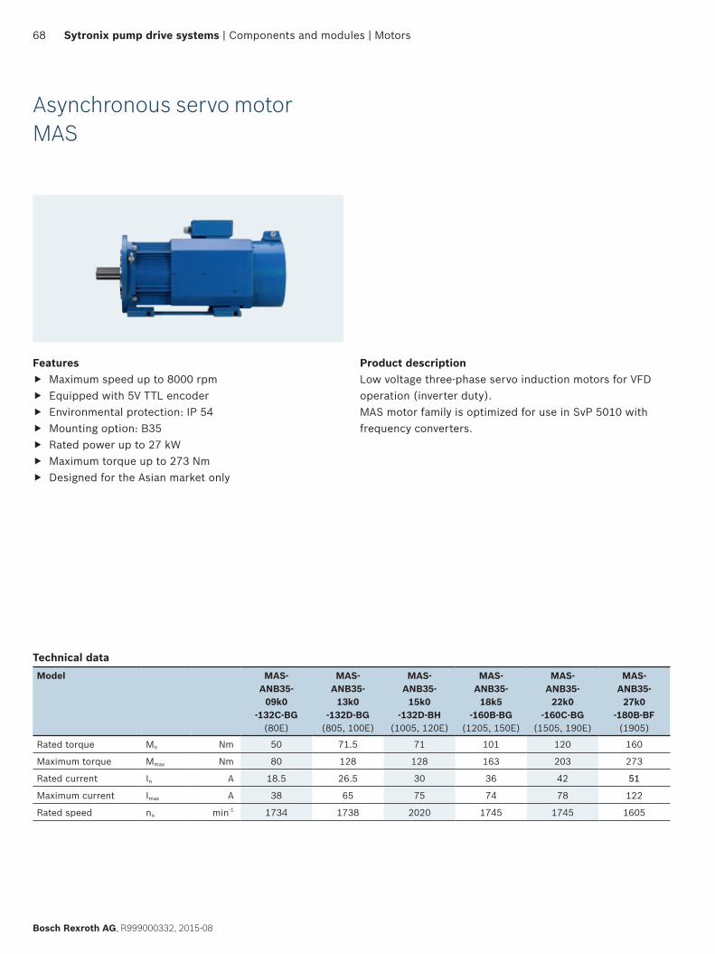
68
Bosch Rexroth AG, R999000332, 2015-08
Sytronix pump drive systems | Components and modules | Motors
Asynchronous servo motorMAS
Features f Maximum speed up to 8000 rpm f Equipped with 5V TTL encoder f Environmental protection: IP 54 f Mounting option: B35 f Rated power up to 27 kW f Maximum torque up to 273 Nm f Designed for the Asian market only
Product descriptionLow voltage three-phase servo induction motors for VFD operation (inverter duty). MAS motor family is optimized for use in SvP 5010 with frequency converters.
Technical dataModel MAS-
ANB35-09k0
-132C-BG(80E)
MAS-ANB35-
13k0-132D-BG
(805, 100E)
MAS-ANB35-
15k0-132D-BH
(1005, 120E)
MAS-ANB35-
18k5-160B-BG
(1205, 150E)
MAS-ANB35-
22k0-160C-BG
(1505, 190E)
MAS-ANB35-
27k0-180B-BF(1905)
Rated torque Mn Nm 50 71.5 71 101 120 160
Maximum torque Mmax Nm 80 128 128 163 203 273
Rated current In A 18.5 26.5 30 36 42 51
Maximum current Imax A 38 65 75 74 78 122
Rated speed nn min-1 1734 1738 2020 1745 1745 1605
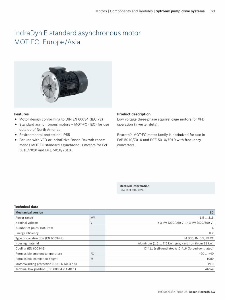
69
R999000332, 2015-08, Bosch Rexroth AG
Motors | Components and modules | Sytronix pump drive systems
IndraDyn E standard asynchronous motorMOT-FC: Europe/Asia
Features f Motor design conforming to DIN EN 60034 (IEC 72) f Standard asynchronous motors – MOT-FC (IEC) for use
outside of North America f Environmental protection: IP55 f For use with VFD or IndraDrive Bosch Rexroth recom-
mends MOT-FC standard asynchronous motors for FcP 5010/7010 and DFE 5010/7010.
Product descriptionLow voltage three-phase squirrel cage motors for VFD operation (inverter duty).
Rexroth’s MOT-FC motor family is optimized for use in FcP 5010/7010 and DFE 5010/7010 with frequency converters.
Detailed information:See R911343624
Technical dataMechanical version IEC
Power range kW 1.5 … 315
Nominal voltage V < 3 kW (230/460 V); > 3 kW (400/690 V)
Number of poles 1500 rpm 4
Energy efficiency IE2
Type of construction (EN 60034-7) IM B35; IM B 5, IM V1
Housing material Aluminum (1.5 … 7.5 kW), gray cast iron (from 11 kW)
Cooling (EN 60034-6) IC 411 (self-ventilated); IC 416 (forced-ventilated)
Permissible ambient temperature °C ‒20 … +40
Permissible installation height m 1000
Motor/winding protection (DIN EN 60947-8) PTC
Terminal box position (IEC 60034-7 AMD 1) Above
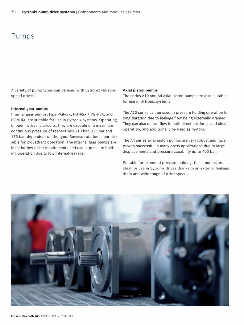
70
Bosch Rexroth AG, R999000332, 2015-08
Sytronix pump drive systems | Components and modules | Pumps
Pumps
A variety of pump types can be used with Sytronix variable- speed drives.
Internal gear pumpsInternal gear pumps, type PGF-2X, PGH-2X / PGH-3X, and PGM-4X, are suitable for use in Sytronix systems. Operating in open hydraulic circuits, they are capable of a maximum continuous pressure of respectively 210 bar, 315 bar and 175 bar, dependent on the type. Reverse rotation is permis-sible for 2-quadrant operation. The internal gear pumps are ideal for low noise requirements and use in pressure hold-ing operation due to low internal leakage.
Axial piston pumpsThe series A10 and A4 axial piston pumps are also suitable for use in Sytronix systems.
The A10 series can be used in pressure holding operation for long duration due to leakage flow being externally drained. They can also deliver flow in both directions for closed circuit operation, and additionally be used as motors.
The A4 series axial piston pumps are very robust and have proven successful in many press applications due to large displacements and pressure capability up to 400 bar.
Suitable for extended pressure holding, these pumps are ideal for use in Sytronix drives thanks to an external leakage drain and wide range of drive speeds.
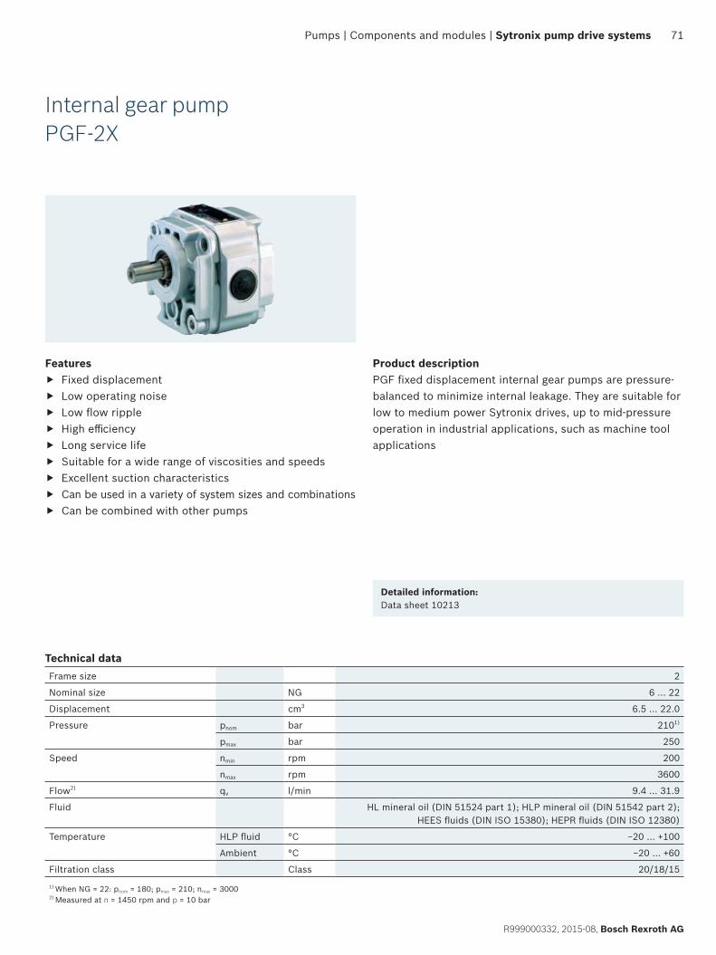
71
R999000332, 2015-08, Bosch Rexroth AG
Pumps | Components and modules | Sytronix pump drive systems
Features f Fixed displacement f Low operating noise f Low flow ripple f High efficiency f Long service life f Suitable for a wide range of viscosities and speeds f Excellent suction characteristics f Can be used in a variety of system sizes and combinations f Can be combined with other pumps
Product descriptionPGF fixed displacement internal gear pumps are pressure-balanced to minimize internal leakage. They are suitable for low to medium power Sytronix drives, up to mid-pressure operation in industrial applications, such as machine tool applications
Detailed information:Data sheet 10213
Technical dataFrame size 2
Nominal size NG 6 … 22
Displacement cm3 6.5 … 22.0
Pressure pnom bar 2101)
pmax bar 250
Speed nmin rpm 200
nmax rpm 3600
Flow2) qv l/min 9.4 … 31.9
Fluid HL mineral oil (DIN 51524 part 1); HLP mineral oil (DIN 51542 part 2); HEES fluids (DIN ISO 15380); HEPR fluids (DIN ISO 12380)
Temperature HLP fluid °C −20 … +100
Ambient °C −20 … +60
Filtration class Class 20/18/15
1) When NG = 22: pnom = 180; pmax = 210; nmax = 3000 2) Measured at n = 1450 rpm and p = 10 bar
Internal gear pumpPGF-2X
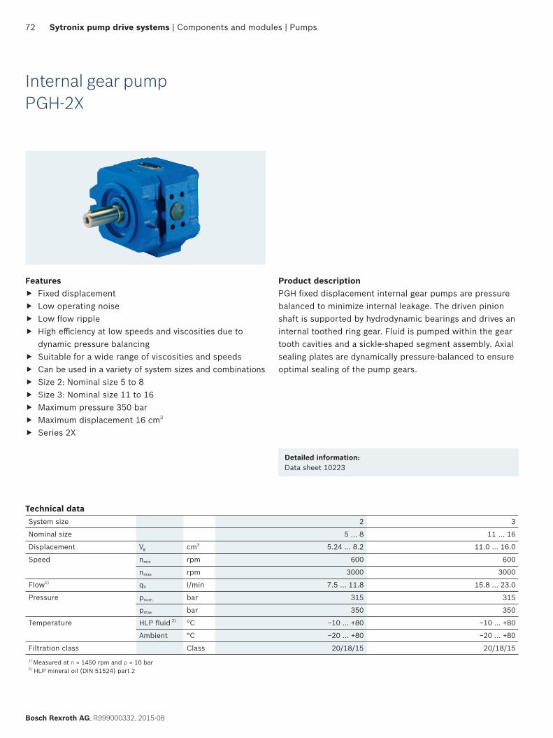
72
Bosch Rexroth AG, R999000332, 2015-08
Sytronix pump drive systems | Components and modules | Pumps
Internal gear pumpPGH-2X
Features f Fixed displacement f Low operating noise f Low flow ripple f High efficiency at low speeds and viscosities due to
dynamic pressure balancing f Suitable for a wide range of viscosities and speeds f Can be used in a variety of system sizes and combinations f Size 2: Nominal size 5 to 8 f Size 3: Nominal size 11 to 16 f Maximum pressure 350 bar f Maximum displacement 16 cm3
f Series 2X
Product descriptionPGH fixed displacement internal gear pumps are pressure balanced to minimize internal leakage. The driven pinion shaft is supported by hydrodynamic bearings and drives an internal toothed ring gear. Fluid is pumped within the gear tooth cavities and a sickle-shaped segment assembly. Axial sealing plates are dynamically pressure-balanced to ensure optimal sealing of the pump gears.
Detailed information:Data sheet 10223
Technical data System size 2 3
Nominal size 5 … 8 11 … 16
Displacement Vg cm3 5.24 … 8.2 11.0 … 16.0
Speed nmin rpm 600 600
nmax rpm 3000 3000
Flow1) qV l/min 7.5 … 11.8 15.8 … 23.0
Pressure pnom bar 315 315
pmax bar 350 350
Temperature HLP fluid 2) °C −10 … +80 −10 … +80
Ambient °C −20 … +80 −20 … +80
Filtration class Class 20/18/15 20/18/151) Measured at n = 1450 rpm and p = 10 bar 2) HLP mineral oil (DIN 51524) part 2
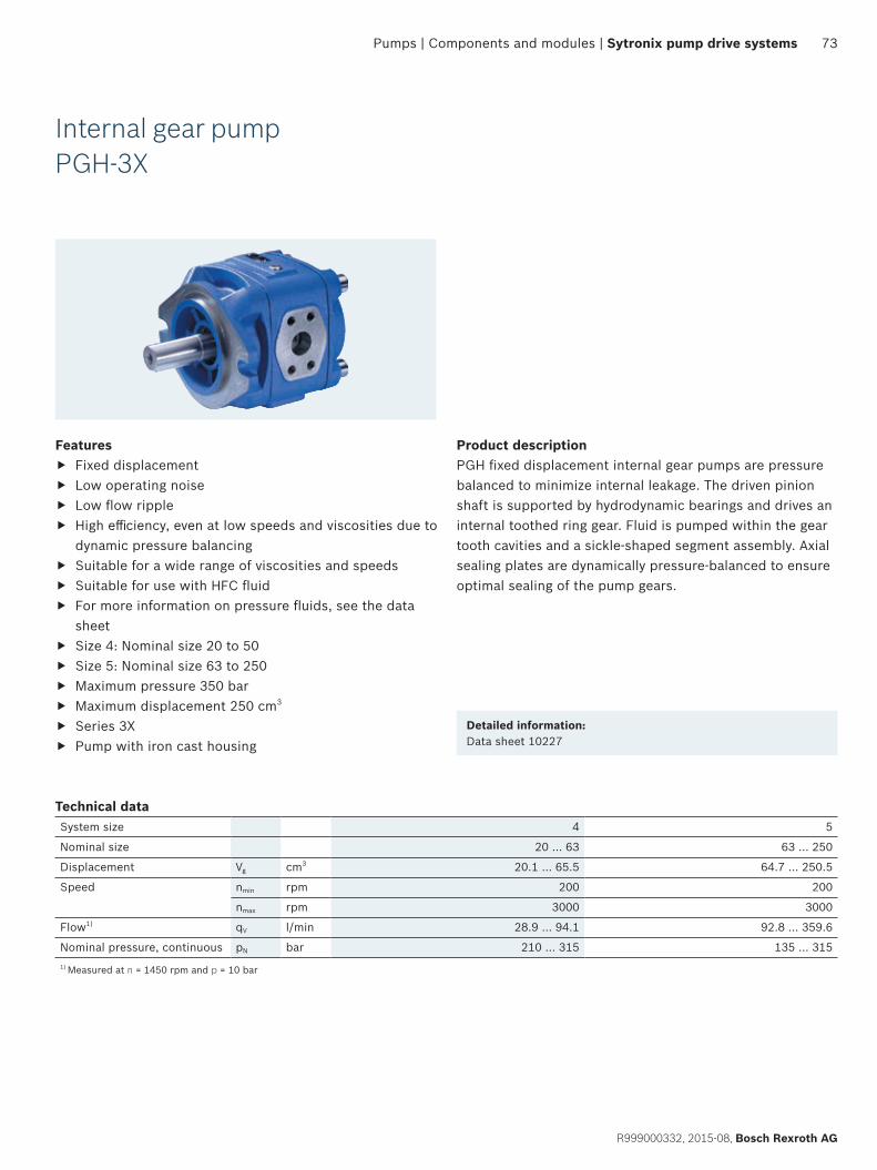
73
R999000332, 2015-08, Bosch Rexroth AG
Pumps | Components and modules | Sytronix pump drive systems
Internal gear pumpPGH-3X
Features f Fixed displacement f Low operating noise f Low flow ripple f High efficiency, even at low speeds and viscosities due to
dynamic pressure balancing f Suitable for a wide range of viscosities and speeds f Suitable for use with HFC fluid f For more information on pressure fluids, see the data
sheet f Size 4: Nominal size 20 to 50 f Size 5: Nominal size 63 to 250 f Maximum pressure 350 bar f Maximum displacement 250 cm3
f Series 3X f Pump with iron cast housing
Product descriptionPGH fixed displacement internal gear pumps are pressure balanced to minimize internal leakage. The driven pinion shaft is supported by hydrodynamic bearings and drives an internal toothed ring gear. Fluid is pumped within the gear tooth cavities and a sickle-shaped segment assembly. Axial sealing plates are dynamically pressure-balanced to ensure optimal sealing of the pump gears.
Detailed information:Data sheet 10227
Technical data System size 4 5
Nominal size 20 … 63 63 … 250
Displacement Vg cm3 20.1 … 65.5 64.7 … 250.5
Speed nmin rpm 200 200
nmax rpm 3000 3000
Flow1) qV l/min 28.9 … 94.1 92.8 … 359.6
Nominal pressure, continuous pN bar 210 … 315 135 … 3151) Measured at n = 1450 rpm and p = 10 bar
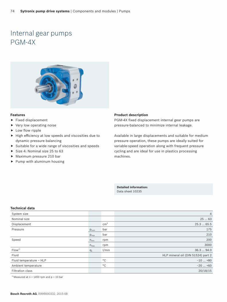
74
Bosch Rexroth AG, R999000332, 2015-08
Sytronix pump drive systems | Components and modules | Pumps
Internal gear pumpsPGM-4X
Features f Fixed displacement f Very low operating noise f Low flow ripple f High efficiency at low speeds and viscosities due to
dynamic pressure balancing f Suitable for a wide range of viscosities and speeds f Size 4: Nominal size 25 to 63 f Maximum pressure 210 bar f Pump with aluminum housing
Product descriptionPGM-4X fixed displacement internal gear pumps are pressure-balanced to minimize internal leakage.
Available in large displacements and suitable for medium pressure operation, these pumps are ideally suited for variable-speed operation along with frequent pressure cycling and are ideal for use in plastics processing machines.
Detailed information:Data sheet 10235
Technical dataSystem size 4
Nominal size 25 … 63
Displacement cm3 25.3 … 65.5
Pressure pnom bar 175
pmax bar 210
Speed nmin rpm 200
nmax rpm 3000
Flow1) qv l/min 36.3 … 94.0
Fluid HLP mineral oil (DIN 51524) part 2
Fluid temperature – HLP °C −10 … +80
Ambient temperature °C −20 … +60
Filtration class 20/18/15
1) Measured at n = 1450 rpm and p = 10 bar
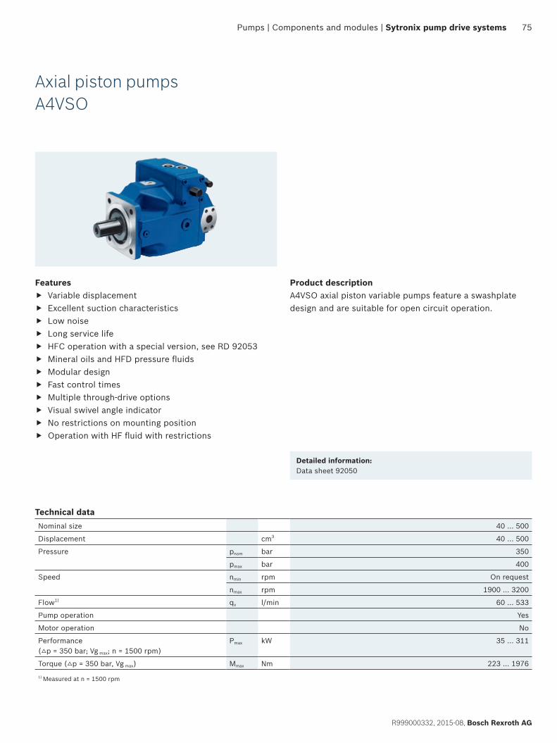
75
R999000332, 2015-08, Bosch Rexroth AG
Pumps | Components and modules | Sytronix pump drive systems
Axial piston pumpsA4VSO
Features f Variable displacement f Excellent suction characteristics f Low noise f Long service life f HFC operation with a special version, see RD 92053 f Mineral oils and HFD pressure fluids f Modular design f Fast control times f Multiple through-drive options f Visual swivel angle indicator f No restrictions on mounting position f Operation with HF fluid with restrictions
Product descriptionA4VSO axial piston variable pumps feature a swashplate design and are suitable for open circuit operation.
Detailed information:Data sheet 92050
Technical dataNominal size 40 … 500
Displacement cm3 40 … 500
Pressure pnom bar 350
pmax bar 400
Speed nmin rpm On request
nmax rpm 1900 … 3200
Flow1) qv l/min 60 … 533
Pump operation Yes
Motor operation No
Performance (△p = 350 bar; Vg max; n = 1500 rpm)
Pmax kW 35 … 311
Torque (△p = 350 bar, Vg max) Mmax Nm 223 … 1976
1) Measured at n = 1500 rpm
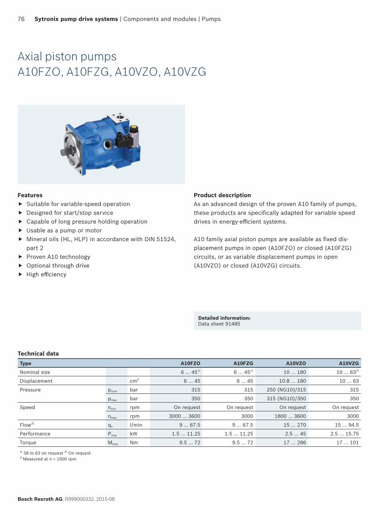
76
Bosch Rexroth AG, R999000332, 2015-08
Sytronix pump drive systems | Components and modules | Pumps
Axial piston pumpsA10FZO, A10FZG, A10VZO, A10VZG
Features f Suitable for variable-speed operation f Designed for start/stop service f Capable of long pressure holding operation f Usable as a pump or motor f Mineral oils (HL, HLP) in accordance with DIN 51524,
part 2 f Proven A10 technology f Optional through drive f High efficiency
Product descriptionAs an advanced design of the proven A10 family of pumps, these products are specifically adapted for variable speed drives in energy-efficient systems.
A10 family axial piston pumps are available as fixed dis-placement pumps in open (A10FZO) or closed (A10FZG) circuits, or as variable displacement pumps in open (A10VZO) or closed (A10VZG) circuits.
Detailed information:Data sheet 91485
Technical dataType A10FZO A10FZG A10VZO A10VZG
Nominal size 6 … 451) 6 … 451) 10 … 180 10 … 632)
Displacement cm3 6 … 45 6 … 45 10.8 … 180 10 … 63
Pressure pnom bar 315 315 250 (NG10)/315 315
pmax bar 350 350 315 (NG10)/350 350
Speed nmin rpm On request On request On request On request
nmax rpm 3000 … 3600 3000 1800 … 3600 3000
Flow3) qv l/min 9 … 67.5 9 … 67.5 15 … 270 15 … 94.5
Performance Pmax kW 1.5 … 11.25 1.5 … 11.25 2.5 … 45 2.5 … 15.75
Torque Mmax Nm 9.5 … 72 9.5 … 72 17 … 286 17 … 101
1) 58 to 63 on request 2) On request 3) Measured at n = 1500 rpm
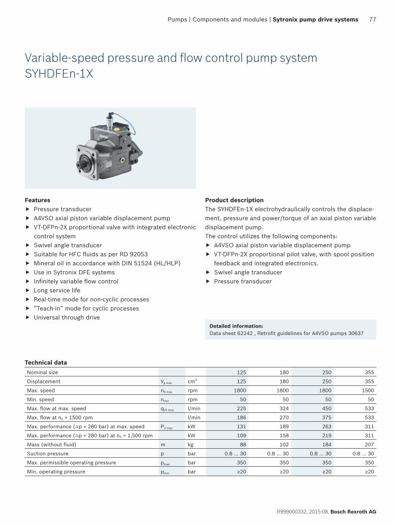
77
R999000332, 2015-08, Bosch Rexroth AG
Pumps | Components and modules | Sytronix pump drive systems
Variable-speed pressure and flow control pump systemSYHDFEn-1X
Product descriptionThe SYHDFEn-1X electrohydraulically controls the displace-ment, pressure and power/torque of an axial piston variable displacement pump.The control utilizes the following components:
f A4VSO axial piston variable displacement pump f VT-DFPn-2X proportional pilot valve, with spool position
feedback and integrated electronics. f Swivel angle transducer f Pressure transducer
Detailed information:Data sheet 62242 , Retrofit guidelines for A4VSO pumps 30637
Features f Pressure transducer f A4VSO axial piston variable displacement pump f VT-DFPn-2X proportional valve with integrated electronic
control system f Swivel angle transducer f Suitable for HFC fluids as per RD 92053 f Mineral oil in accordance with DIN 51524 (HL/HLP) f Use in Sytronix DFE systems f Infinitely variable flow control f Long service life f Real-time mode for non-cyclic processes f ”Teach-in” mode for cyclic processes f Universal through drive
Technical dataNominal size 125 180 250 355
Displacement Vg max cm3 125 180 250 355
Max. speed n0 max rpm 1800 1800 1800 1500
Min. speed nmin rpm 50 50 50 50
Max. flow at max. speed qv0 max l/min 225 324 450 533
Max. flow at nE = 1500 rpm l/min 186 270 375 533
Max. performance (△p = 280 bar) at max. speed P0 max kW 131 189 263 311
Max. performance (△p = 280 bar) at nE = 1,500 rpm kW 109 158 219 311
Mass (without fluid) m kg 88 102 184 207
Suction pressure p bar 0.8 … 30 0.8 … 30 0.8 … 30 0.8 … 30
Max. permissible operating pressure pmax bar 350 350 350 350
Min. operating pressure pmin bar ≥20 ≥20 ≥20 ≥20
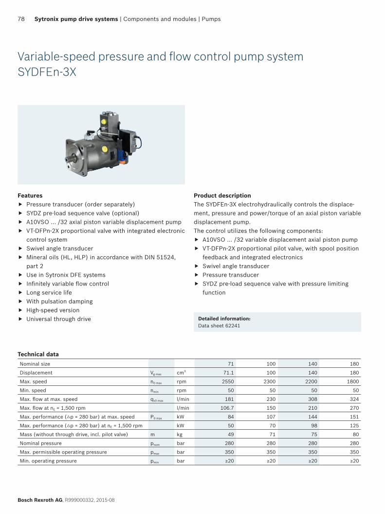
78
Bosch Rexroth AG, R999000332, 2015-08
Sytronix pump drive systems | Components and modules | Pumps
Variable-speed pressure and flow control pump systemSYDFEn-3X
Product descriptionThe SYDFEn-3X electrohydraulically controls the displace-ment, pressure and power/torque of an axial piston variable displacement pump.The control utilizes the following components:
f A10VSO … /32 variable displacement axial piston pump f VT-DFPn-2X proportional pilot valve, with spool position
feedback and integrated electronics f Swivel angle transducer f Pressure transducer f SYDZ pre-load sequence valve with pressure limiting
function
Detailed information:Data sheet 62241
Features f Pressure transducer (order separately) f SYDZ pre-load sequence valve (optional) f A10VSO … /32 axial piston variable displacement pump f VT-DFPn-2X proportional valve with integrated electronic
control system f Swivel angle transducer f Mineral oils (HL, HLP) in accordance with DIN 51524,
part 2 f Use in Sytronix DFE systems f Infinitely variable flow control f Long service life f With pulsation damping f High-speed version f Universal through drive
Technical dataNominal size 71 100 140 180
Displacement Vg max cm3 71.1 100 140 180
Max. speed n0 max rpm 2550 2300 2200 1800
Min. speed nmin rpm 50 50 50 50
Max. flow at max. speed qv0 max l/min 181 230 308 324
Max. flow at nE = 1,500 rpm l/min 106.7 150 210 270
Max. performance (△p = 280 bar) at max. speed P0 max kW 84 107 144 151
Max. performance (△p = 280 bar) at nE = 1,500 rpm kW 50 70 98 125
Mass (without through drive, incl. pilot valve) m kg 49 71 75 80
Nominal pressure pnom bar 280 280 280 280
Max. permissible operating pressure pmax bar 350 350 350 350
Min. operating pressure pmin bar ≥20 ≥20 ≥20 ≥20
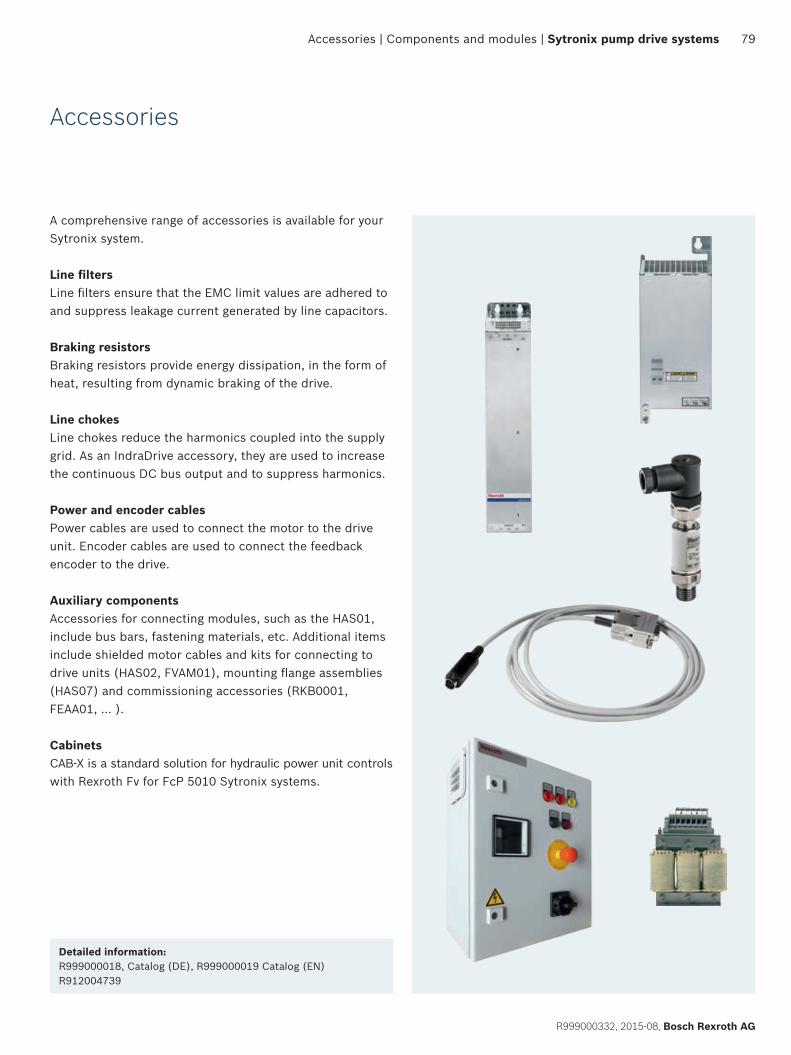
79
R999000332, 2015-08, Bosch Rexroth AG
Accessories | Components and modules | Sytronix pump drive systems
Accessories
A comprehensive range of accessories is available for your Sytronix system.
Line filtersLine filters ensure that the EMC limit values are adhered to and suppress leakage current generated by line capacitors.
Braking resistorsBraking resistors provide energy dissipation, in the form of heat, resulting from dynamic braking of the drive.
Line chokesLine chokes reduce the harmonics coupled into the supply grid. As an IndraDrive accessory, they are used to increase the continuous DC bus output and to suppress harmonics.
Power and encoder cablesPower cables are used to connect the motor to the drive unit. Encoder cables are used to connect the feedback encoder to the drive.
Auxiliary componentsAccessories for connecting modules, such as the HAS01, include bus bars, fastening materials, etc. Additional items include shielded motor cables and kits for connecting to drive units (HAS02, FVAM01), mounting flange assemblies (HAS07) and commissioning accessories (RKB0001, FEAA01, … ).
CabinetsCAB-X is a standard solution for hydraulic power unit controls with Rexroth Fv for FcP 5010 Sytronix systems.
Detailed information:R999000018, Catalog (DE), R999000019 Catalog (EN)R912004739
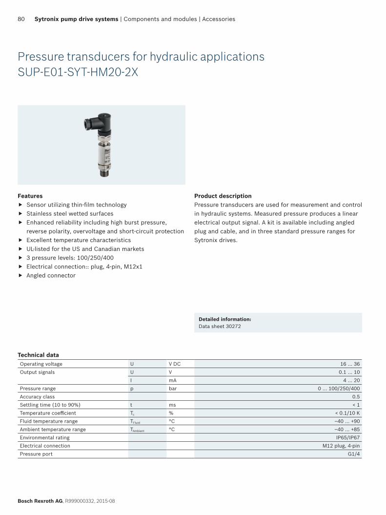
80
Bosch Rexroth AG, R999000332, 2015-08
Sytronix pump drive systems | Components and modules | Accessories
Pressure transducers for hydraulic applicationsSUP-E01-SYT-HM20-2X
Features f Sensor utilizing thin-film technology f Stainless steel wetted surfaces f Enhanced reliability including high burst pressure,
reverse polarity, overvoltage and short-circuit protection f Excellent temperature characteristics f UL-listed for the US and Canadian markets f 3 pressure levels: 100/250/400 f Electrical connection:: plug, 4-pin, M12x1 f Angled connector
Product descriptionPressure transducers are used for measurement and control in hydraulic systems. Measured pressure produces a linear electrical output signal. A kit is available including angled plug and cable, and in three standard pressure ranges for Sytronix drives.
Technical data Operating voltage U V DC 16 … 36Output signals U V 0.1 … 10
I mA 4 … 20 Pressure range p bar 0 … 100/250/400Accuracy class 0.5Settling time (10 to 90%) t ms < 1Temperature coefficient Tc % < 0.1/10 KFluid temperature range TFluid °C –40 … +90Ambient temperature range TAmbient °C –40 … +85Environmental rating IP65/IP67Electrical connection M12 plug, 4-pinPressure port G1/4
Detailed information:Data sheet 30272
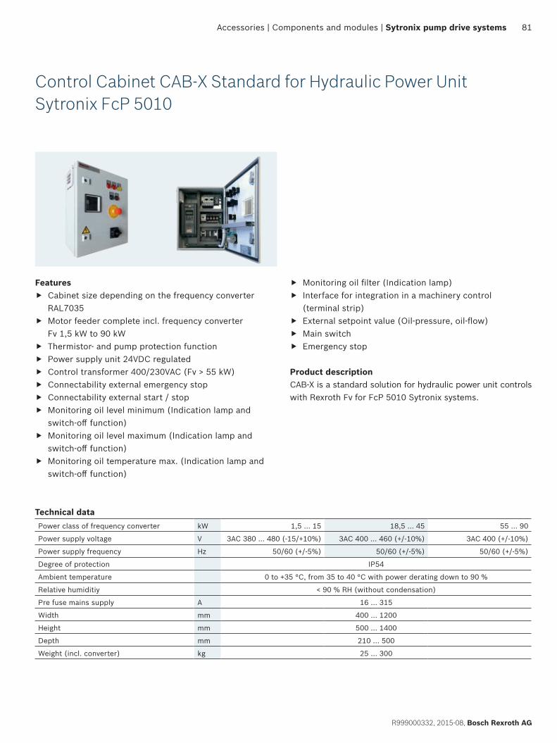
81
R999000332, 2015-08, Bosch Rexroth AG
Accessories | Components and modules | Sytronix pump drive systems
Control Cabinet CAB-X Standard for Hydraulic Power Unit Sytronix FcP 5010
f Monitoring oil filter (Indication lamp) f Interface for integration in a machinery control
(terminal strip) f External setpoint value (Oil-pressure, oil-flow) f Main switch f Emergency stop
Product descriptionCAB-X is a standard solution for hydraulic power unit controls with Rexroth Fv for FcP 5010 Sytronix systems.
Features f Cabinet size depending on the frequency converter
RAL7035 f Motor feeder complete incl. frequency converter
Fv 1,5 kW to 90 kW f Thermistor- and pump protection function f Power supply unit 24VDC regulated f Control transformer 400/230VAC (Fv > 55 kW) f Connectability external emergency stop f Connectability external start / stop f Monitoring oil level minimum (Indication lamp and
switch-off function) f Monitoring oil level maximum (Indication lamp and
switch-off function) f Monitoring oil temperature max. (Indication lamp and
switch-off function)
Technical dataPower class of frequency converter kW 1,5 … 15 18,5 … 45 55 … 90
Power supply voltage V 3AC 380 … 480 (-15/+10%) 3AC 400 … 460 (+/-10%) 3AC 400 (+/-10%)
Power supply frequency Hz 50/60 (+/-5%) 50/60 (+/-5%) 50/60 (+/-5%)
Degree of protection IP54
Ambient temperature 0 to +35 °C, from 35 to 40 °C with power derating down to 90 %
Relative humiditiy < 90 % RH (without condensation)
Pre fuse mains supply A 16 … 315
Width mm 400 … 1200
Height mm 500 … 1400
Depth mm 210 … 500
Weight (incl. converter) kg 25 … 300
Find your personal contact person here:www.boschrexroth.com/contact
Bosch Rexroth AGZum Eisengießer 1 97816 Lohr, Germany www.boschrexroth.com
R999000332 (2015-08)© Bosch Rexroth AG 2015Subject to revisions!
The data specified above only serve to describe the product. No statements concerning a certain condition or suitability for a certain application can be derived from our information. The information given does not release the user from the obligation of own judgment and verification. It must be remembered that our products are subject to a natural process of wear and aging.
Further information:www.boschrexroth.com/sytronix