Systems Engineering Solar Decathalon Source Group Midterm...
19
Systems Engineering Solar Decathalon Source Group Midterm Presentation David Daily, Iman Malakooti, Iain Kierzewski, Parastoo Delgoshaei
Transcript of Systems Engineering Solar Decathalon Source Group Midterm...

Systems Engineering Solar Decathalon Source Group
Midterm Presentation
David Daily, Iman Malakooti, Iain Kierzewski, Parastoo Delgoshaei

Inspiration - University of Maryland Solar Decathlon Entry: WaterShed

Contents • System Objective • Functional Requirements • Non-Functional Requirements • List of Assumptions • Use Case Diagram • Goals and Scenarios • Structure Diagram • Relationship Diagram • Parameters Structure Diagram • Parametric Diagram • Requirements Diagram • State Chart • Activity Diagram • Sequence Diagram

System Objective
• The system object is to: develop a system to model the effect of different technologies on the temperature within a room
• This model will include the different constructions of window and wall material, the effects of an automated HVAC system, and the side effects from common heat generating appliances.
• Considerations will need to be given to the weather conditions.

Non-Functional Requirements
User must be able to set: 1. Desired Interior Ambient Temperature 2. Wall properties 3. Window properties 4. Appliance properties 5. Weather time frame 6. Simulation time frame

Functional Requirements
1. System should model and follow equations for heat flux and black-body radiation1,2
2. System should follow a set weather condition based on weather time frame parameter
3. HVAC is activated when a difference of 2 degrees from Desired Temperature is present
4. Minimum Ventilation standard is at 75 CFM3

List of Assumptions
1. Exterior Ambient Temperature is an infinite source/sink 2. Interior Ambient Temperature experiences no diffusion (i.e. heat in
is automatically evenly distributed throughout the space) 3. Interior Airflow is negligible 4. HVAC system operates at 100% efficiency 5. ERV is constantly working 6. 80% of heat used for Appliances is released back into interior space 7. No heat is absorbed in mediums (perfect conduction) 8. House is Wx2W sized plan with one window facing South 9. Threshold for HVAC system is +/- 2 degrees from Desired Int Amb
Temp 10. R value is proportional to k/d in conduction equation 11. Each simulation starts with Int Amb Temp at Desired Amb Temp

Use Case Diagram

Goals and Scenarios
Goals 1. Allow homeowner to adjust conditioned space temperature • Scenario 1.1: Summer, Day • Scenario 1.2: Fall, Day • Scenario 1.3: Winter, Day • Scenario 1.4: Spring, Day • Scenario 1.5: Summer, Night • Scenario 1.6: Fall, Night • Scenario 1.7: Winter, Night • Scenario 1.8: Spring, Night
Goals 2. Show the effect of changing the wall material on the temperature of a room • Scenario 2.1: Low R Value • Scenario 2.2: Medium R Value • Scenario 2.3: High R Value

Goals and Scenarios
Goals 3. Show the effect of changing the window material on the temperature of a room • Scenario 3.1: Single Pane, Low SHGC • Scenario 3.2: Single Pane, High SHGC • Scenario 3.3: Double Pane, Low SHGC • Scenario 3.4: Double Pane, High SHGC • Scenario 3.5: Triple Pane, Low SHGC • Scenario 3.6: Triple Pane, High SHGC
Goals 4. Show the effect of appliance type on the temperature of a room • Scenario 4.1: High Efficiency Appliances • Scenario 4.2: Standard Appliances

Structure Diagram

Relationship Diagram
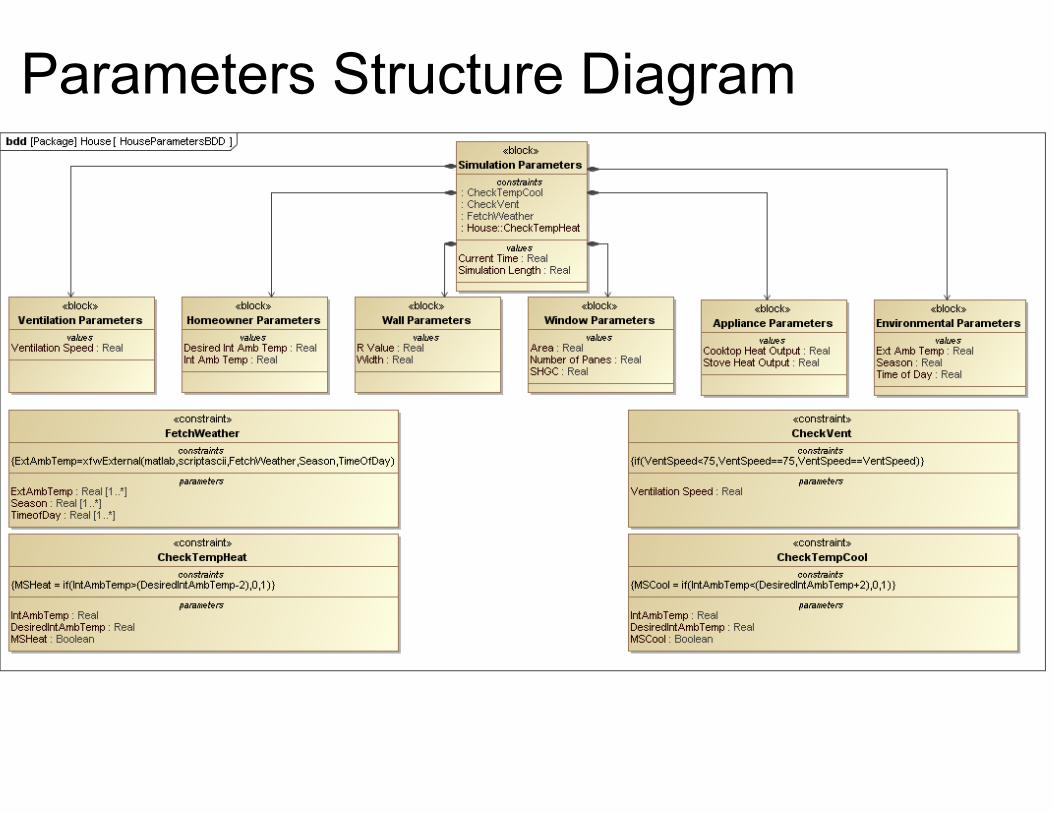
Parameters Structure Diagram

Parametric Diagram

Requirements Diagram

State Chart

Activity Diagram

Sequence Diagram

Sources
1. http://hyperphysics.phy-astr.gsu.edu/hbase/mod6.html 2. http://hyperphysics.phy-astr.gsu.edu/hbase/hframe.html 3. International Residential Code 2009