Systems Engineering Seminar – Orbital Debris Mitigation Scott Hull and Josephine San, 591 October...
60
Systems Engineering Seminar – Orbital Debris Mitigation Scott Hull and Josephine San, 591 October 7, 2003 1 Orbital Debris Mitigation Safe Disposal Planning Begins at Concept Design Scott Hull Josephine San GSFC Code 591
-
Upload
christina-taylor -
Category
Documents
-
view
219 -
download
2
Transcript of Systems Engineering Seminar – Orbital Debris Mitigation Scott Hull and Josephine San, 591 October...

Systems Engineering Seminar – Orbital Debris Mitigation Scott Hull and Josephine San, 591 October 7, 2003
1
Orbital Debris MitigationSafe Disposal Planning Begins at
Concept Design
Scott Hull
Josephine San
GSFC Code 591

Systems Engineering Seminar – Orbital Debris Mitigation Scott Hull and Josephine San, 591 October 7, 2003
2
Agenda
• Overview of NPD 8710.3 and NSS 1740.14, Scott Hull And Reentry Analysis Basics
• GSFC Safe Disposal Planning Josephine San
• Design for Demise Examples Scott Hull
• Current Status Scott Hull

Systems Engineering Seminar – Orbital Debris Mitigation Scott Hull and Josephine San, 591 October 7, 2003
3
Overview of DocumentationAnd Reentry Analysis Basics
Scott Hull / 591
NASA/GSFC

Systems Engineering Seminar – Orbital Debris Mitigation Scott Hull and Josephine San, 591 October 7, 2003
4
NASA Policy
• Debris assessment shall be done for all missions at mission PDR and CDR
• Design for safe disposal at the end of the mission
• Notify other government agencies when NASA related hardware reenters
• Promote international cooperation on debris related issues

Systems Engineering Seminar – Orbital Debris Mitigation Scott Hull and Josephine San, 591 October 7, 2003
5
Applicable Documents• NPD 8710.3A
– Recently revised– Requires an ODA to be written– Invokes NSS 1740.14
• NSS 1740.14 (to be replaced by NS 8719.14)– Guidelines for debris mitigation– Evaluation instructions
• GSFC ISO Documents– Debris Mitigation– Controlled Reentry– Reentry Survivability
Systems Engineering Seminar – Orbital Debris Mitigation Scott Hull and Josephine San, 591 October 7, 2003
6
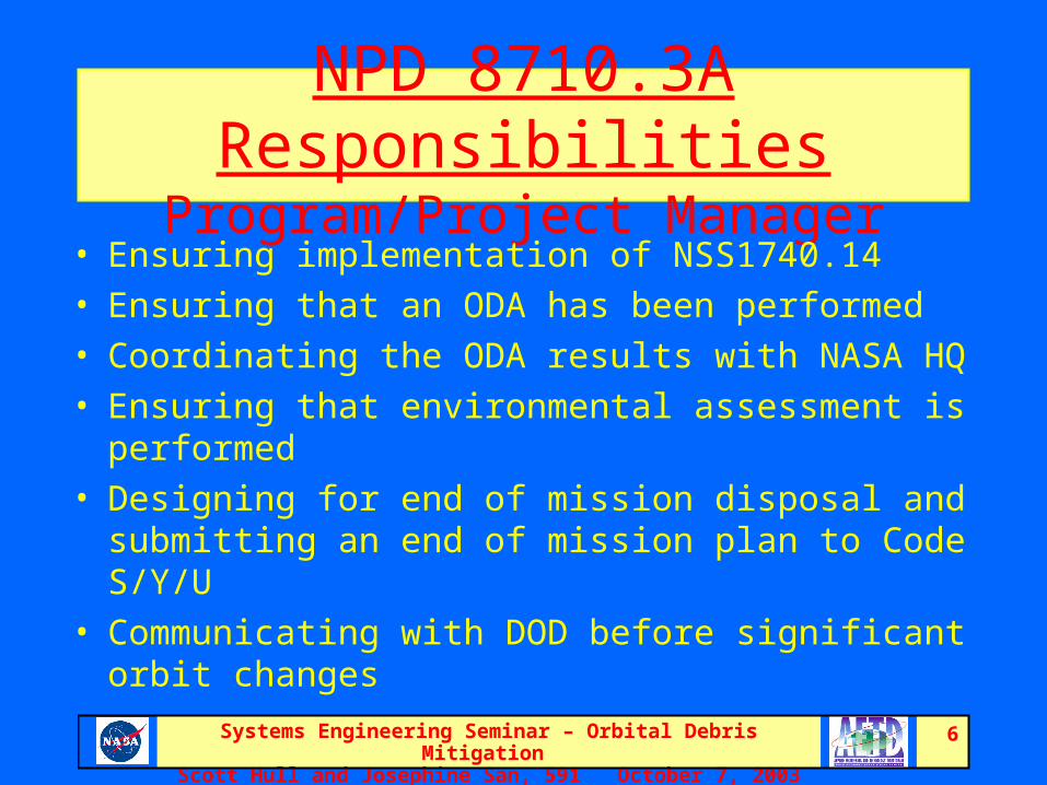
NPD 8710.3A ResponsibilitiesProgram/Project Manager
• Ensuring implementation of NSS1740.14
• Ensuring that an ODA has been performed
• Coordinating the ODA results with NASA HQ
• Ensuring that environmental assessment is performed
• Designing for end of mission disposal and submitting an end of mission plan to Code S/Y/U
• Communicating with DOD before significant orbit changes

Systems Engineering Seminar – Orbital Debris Mitigation Scott Hull and Josephine San, 591 October 7, 2003
7
NPD 8710.3A ResponsibilitiesNASA Headquarters
• Code S/Y/U– Approving ODA reports– Reviewing the cost analysis if applicable– Approving the end of mission plan
• Code Q– Establishing policies– Providing guidelines and standards– Reviewing ODA reports and end of mission plans– Providing software tools for evaluating orbital debris– Coordinating NASA reentry information within the agency
• Code I– Coordinating international agreements– Developing procedures for coordinating information on significant reentries with other
US government agencies– Coordinating pre-reentry press releases with the National Security Council and the
White House Office of Science and Technology Policy
• Code P– Coordinating pre-reentry press releases

Systems Engineering Seminar – Orbital Debris Mitigation Scott Hull and Josephine San, 591 October 7, 2003
8
NPD 8710.3A ResponsibilitiesJSC Orbital Debris Program Office
• Maintaining the orbital debris environment models• Providing technical guidance on ODA issues• Providing technical review of ODA reports• Reviewing end of mission plans• Providing technical and policy guidance to all NASA
HQ offices and centers• Maintaining a list of reentry predictions
– Updated every six months– Sent to Code Q
• Promoting the use of international guidelines

Systems Engineering Seminar – Orbital Debris Mitigation Scott Hull and Josephine San, 591 October 7, 2003
9
Orbital Debris Assessment (ODA)Report Review Process
• Program/Project Manager sends report to Code S/Y/U
• Code S/Y/U forwards it to Code Q• Code Q forwards it to JSC-ODPO• JSC-ODPO review comments sent back
through Code Q to Code S/Y/U• Code S/Y/U Associate Administrator
makes the final decision whether to accept the ODA and disposal plans

Systems Engineering Seminar – Orbital Debris Mitigation Scott Hull and Josephine San, 591 October 7, 2003
10
What is in an ODA?• Executive Summary• Section 1: Introduction• Section 2: Spacecraft/Mission Description • Section 3: Operational Debris• Section 4: Accidental Explosions and
Intentional Breakups• Section 5: On-orbit Collision Risk• Section 6: Postmission Disposal• Section 7: Reentry Survivability • Conclusion

Systems Engineering Seminar – Orbital Debris Mitigation Scott Hull and Josephine San, 591 October 7, 2003
11
ODA Conclusions
• Assessment was performed per NPD 8710.3A
• Overall findings– All applicable guidelines were met– All but X, Y, and Z were met
• Table of findings is recommended– Include all guidelines– Indicate whether each is Met, Not Met, or Not
Applicable, and any necessary comments
• Always include the DCA and casualty odds

Systems Engineering Seminar – Orbital Debris Mitigation Scott Hull and Josephine San, 591 October 7, 2003
12
NSS 1740.14 Guidelines
• Basically follows the report structure
• Report doesn’t necessarily call out all of the guidelines, though
• 14 guidelines, 7 sections
• Table of findings helps to prevent holes
• Most heavily scrutinized are 4-2, 5-1, 5-2, 6-1, 6-4, and 7-1

Systems Engineering Seminar – Orbital Debris Mitigation Scott Hull and Josephine San, 591 October 7, 2003
13
NSS 1740.14 Guideline 4-2
Accidental Explosions Postmission– Risk to other spacecraft– “All on-board sources of stored energy will
be depleted when they are no longer required for mission operations or postmission disposal.”
Proposed change: Recommendation to perform propellant depletion burns to reduce orbit lifetime.

Systems Engineering Seminar – Orbital Debris Mitigation Scott Hull and Josephine San, 591 October 7, 2003
14
NSS 1740.14 Guideline 6-1Disposal from orbits passing through LEO
(choose one)
6-1 a. Atmospheric reentry• Orbit decay < 25 years after end of mission• Uncontrolled reentry• Controlled reentry
6-1 b. Maneuver to a storage orbitPerigee > 2500 km, Apogee < 35,288 km
6-1 c. Direct retrieval
Proposed changes:– Orbital lifetime < 30 years– Specific language on controlled reentry– Perigee > 2000 km, Apogee < 35,588 km

Systems Engineering Seminar – Orbital Debris Mitigation Scott Hull and Josephine San, 591 October 7, 2003
15
NSS 1740.14 Guideline 6-4
Reliability of Postmission Disposal– Applies to both spacecraft and upper
stages– Identify all credible failure modes– Probability of success > 0.99
Proposed change: Reliability of > 0.90 acceptable if not performing controlled reentry.

Systems Engineering Seminar – Orbital Debris Mitigation Scott Hull and Josephine San, 591 October 7, 2003
16
NSS 1740.14 Guideline 7-1
• Risk from Surviving Debris– Only applies to atmospheric reentry– Function of spacecraft construction and materials
chosen
– Debris Casualty Area < 8 m2
– Complex simulation
• Proposed changes: Reentry risk < 1 in 10,000
considering inclination and year of reentry; casualty
threshold (> 15J) added officially

Systems Engineering Seminar – Orbital Debris Mitigation Scott Hull and Josephine San, 591 October 7, 2003
17
Debris Casualty Area (DCA)The DCA is the portion of the Earth surface on which a person is likely to be injured by a piece of falling debris.When an object survives, a 0.3m “man-border” is essentially added to the circumference of the object

Systems Engineering Seminar – Orbital Debris Mitigation Scott Hull and Josephine San, 591 October 7, 2003
18
Reentry Process
• Atmosphere entry: 122 km altitude
• Appendages breakoff
• Catastrophic breakup: Typically ~78 km– Some recent evidence for lower breakup
on larger spacecraft
• Object burnup: Generally ~80 to 55 km
• Cooling / survival: Below ~50 km

Systems Engineering Seminar – Orbital Debris Mitigation Scott Hull and Josephine San, 591 October 7, 2003
19
Reentry TermsControlled
ReentryTargeted Time & Place
Uncontrolled ReentryWhen? Where?
Breakup
Burnup
Land? Water? Ocean

Systems Engineering Seminar – Orbital Debris Mitigation Scott Hull and Josephine San, 591 October 7, 2003
20
Effort Spent on Reentry Simulation
40%
20%
10%
10% 10%
10%
Gather Data
Envision Breakup
Organize Data
Simulate Reentry
Review Output
Write Report

Systems Engineering Seminar – Orbital Debris Mitigation Scott Hull and Josephine San, 591 October 7, 2003
21
Component Modeling
• Spacecraft components need to be modeled as one of four shapes:Sphere Cylinder Box Flat Plate
• Choice is based on preserving surface area and cross-sectional area
• Many real components are difficult to model

Systems Engineering Seminar – Orbital Debris Mitigation Scott Hull and Josephine San, 591 October 7, 2003
22
Component ModelingExample - Washer
• Circular top view resembles cylinder• Side view resembles a box• If tumbling, sweeps out a sphere• If cut and straightened, flat plate results• JSC recommends using a flat plate model

Systems Engineering Seminar – Orbital Debris Mitigation Scott Hull and Josephine San, 591 October 7, 2003
23
Ablation
• An object is said to have ablated (demised) when it has fully melted
• Heat of Ablation
HAblat = Mass x [Cp x (Tmelt – T init) + HFusion]
• Heat Balance Equationqnet = qconv + qrad + qox – qrr
qconv = average aerodynamic heating
qrad = gas cap radiation heating
qox = oxidation heating
qrr = reradiative cooling

Systems Engineering Seminar – Orbital Debris Mitigation Scott Hull and Josephine San, 591 October 7, 2003
24
DAS Software Overview
• Debris Assessment Software• Written by JSC ODPO• Very useful for evaluating Guidelines 5, 6, and 7• Current version is 1.5.3
– Stand-alone software• Downloadable from JSC ODPO web site
– Web-based interface• Available to to GSFC domains only at this time
– Version 2.0 to be released soon

Systems Engineering Seminar – Orbital Debris Mitigation Scott Hull and Josephine San, 591 October 7, 2003
25
DAS SoftwareGuideline 7 (slide 1 of 2)
• Program Variables– Breakup Altitude– Object Inputs (saved in a text file)
• Name, Shape, Dimensions, Mass, Material– Materials Inputs
• Only uses Specific Heat, Heat of Fusion, and Melt Temp• Synthetic Materials
– Allows an assembly to be modeled with two masses• Aero mass – total mass of the assembly• Thermal mass – mass of the container/ structure
Web-interface version accepts inputs from Excel

Systems Engineering Seminar – Orbital Debris Mitigation Scott Hull and Josephine San, 591 October 7, 2003
26
DAS SoftwareGuideline 7 (slide 2 of 2)
• Evaluation Results– Simulation Output
• Repeats input information• Demise Altitude• Debris Casualty Area• DCA Total
– Output can be saved or printed– Easy to make small changes and re-run

Systems Engineering Seminar – Orbital Debris Mitigation Scott Hull and Josephine San, 591 October 7, 2003
27
ORSAT SoftwareInputs
• All contained in one input file per run– Start / Stop altitudes– Parent object shape, dimensions, mass,
material, trajectory– Fragment object shapes, dimensions,
masses, materials
• Separate file for each new material– If three objects with that material, three files

Systems Engineering Seminar – Orbital Debris Mitigation Scott Hull and Josephine San, 591 October 7, 2003
28
ORSAT SoftwareInputs
• Additional capabilities over DAS– Directly entered thermal masses (sort of)– More detailed analysis
• Up to 15 nodes per object• Multiple material layers per object• Oxidation heating, Radiative cooling
– Ability to scale heating factors– Parametric studies– Specified trajectory

Systems Engineering Seminar – Orbital Debris Mitigation Scott Hull and Josephine San, 591 October 7, 2003
29
ORSAT SoftwareSimulation Routine
• Same basic routine as DAS /MORSAT• Five simultaneous modules
– Trajectory: velocity and path of the object– Atmosphere: environment around the object– Aerodynamics: drag experienced by the object– Aerothermodynamics: heating of the object– Thermodynamics: response of the object to heat
• Continuous calculations at small time intervals• Concludes when object either completely
melts or reaches the stop altitude• Software goes on to next object
Systems Engineering Seminar – Orbital Debris Mitigation Scott Hull and Josephine San, 591 October 7, 2003
30
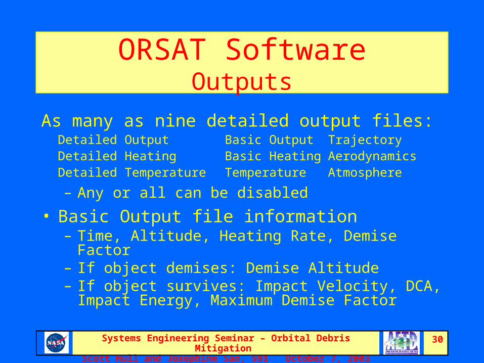
ORSAT SoftwareOutputs
As many as nine detailed output files:Detailed Output Basic Output Trajectory Detailed Heating Basic Heating AerodynamicsDetailed Temperature Temperature Atmosphere
– Any or all can be disabled
• Basic Output file information– Time, Altitude, Heating Rate, Demise Factor– If object demises: Demise Altitude– If object survives: Impact Velocity, DCA, Impact
Energy, Maximum Demise Factor

Systems Engineering Seminar – Orbital Debris Mitigation Scott Hull and Josephine San, 591 October 7, 2003
31
Safe Disposal Planning GSFC Practical Guidelines
Josephine San/591
NASA/GSFC

Systems Engineering Seminar – Orbital Debris Mitigation Scott Hull and Josephine San, 591 October 7, 2003
32
Practical Guidelines - Content
• Objectives • Background• Concept Design Phase – Safe Disposal Planning
begins at Concept Design• Preliminary and Critical Design Phases – Design
Considerations and Planning to Successfully Achieve Safe Disposal
• Operation and End-of-Mission Phases – Implementation of End-of-Mission Plan

Systems Engineering Seminar – Orbital Debris Mitigation Scott Hull and Josephine San, 591 October 7, 2003
33
Objectives and Bases
• Objectives– To Provide Practical Guidance in Compliance With NPD
8710.3 and NSS 1740.14 (to Be NASA Standard 8719.14)– To Assist Projects and Engineers in the Planning of Safe
Disposal– To Prevent Reinventing the Wheel
• Bases– NPD 8710.3 and NSS 1740.14– Experiences From CGRO, TRMM, ERBS, LandSat– Experiences From GLAST, GPM

Systems Engineering Seminar – Orbital Debris Mitigation Scott Hull and Josephine San, 591 October 7, 2003
34
Background - Procedures and Guidelines
• Orbital Debris Mitigation PG– Provide Practical Guidelines on Orbital Debris Analysis– Discuss Design Process Flow to Decide on A Safe Disposal Method– Address Design Considerations, Necessary Analysis and Planning to
Achieve Safe Disposal Through Concept, to Preliminary and Critical Design Phases
– Status: In the Process of AETD Review, and Will Be Ready for Projects and Code 300 Review by the End of the Month
• End-of-Mission Planning PG– Discuss Necessary Planning for Safe Disposal at the End of the
Mission – Provide Guidance on the Development and Implementation of the
End-of-mission Plan– Serve As a Template for End-of-mission Plan– Status: Ready for Peer Review by the End of the Month

Systems Engineering Seminar – Orbital Debris Mitigation Scott Hull and Josephine San, 591 October 7, 2003
35
Background - Procedures and Guidelines (cont.)
• Guidance, Navigation and Control Safe Disposal PG– Provide Guidance to Assist GN&C Flight Dynamic Engineers in the
Mission Planning and End-of-Mission Operation Planning for Safe Disposal
– Status: In the Process of Developing
• Reentry Survivability Analysis Work Instruction– Provide Detailed Instructions on Reentry Survivability Analysis
Using Debris Analysis Software (DAS) and Object Reentry Survivability Analysis Tool (ORSAT)
– Clarify Details of NSS 1740.14
– Establish a Standard Approach for All GSFC Reentry Analysis
– Status: Ready to Submit to ISO

Systems Engineering Seminar – Orbital Debris Mitigation Scott Hull and Josephine San, 591 October 7, 2003
36
Safe Disposal Methods
• Controlled Reentry Method– Maneuver the Spacecraft at the End of Mission to a Disposal Orbit With a Perigee Altitude
Low Enough to Control the Location of the Reentry and Ground Impact Point
– Is Applicable to a Spacecraft which Reenters Earth Atmosphere (Usually Spacecraft at or Passing Through Low Earth Orbit Altitude), and Does Not Meet the 1 in 10,000 Casualty Risk Guideline
• Orbit Raising or Lowering Method– Maneuver the Spacecraft to a Storage Orbit by Raising or Lowering Its Final Orbit at the
End of Mission; Is Applicable to Spacecraft With Perigee Above 2000 Km
– At the End of Mission, Lower the Final Perigee So That It Will Meet the Orbit Life Time Guideline; Is Applicable to Spacecraft With Perigee Below 2000 Km (Uncontrolled Reentry)
• Passivation– Put Spacecraft in Passive State With No Energy Source
– Is Applicable to a Spacecraft which Meets the NSS Safe Disposal Guidelines
• Direct Retrieval– By Shuttle or Other Means

Systems Engineering Seminar – Orbital Debris Mitigation Scott Hull and Josephine San, 591 October 7, 2003
37
Concept Design Process FlowFor Selection of Safe Disposal Method
No
Need Orbit ManeuverTo Meet 25 Year Orbit Life
Or to Remove Spacecraft From Crowded Area?
ConceptDesign
Re-entrySurvivability Analysis using
DAS
Redesign to Reduce
Debris Casualty
Risk?
ControlledRe-entry Method
Casualty risk < 1 in 10,000
YesCasualty risk > 1 in 10,000
Re-entrySurvivability
Analysis Using ORSAT
Casualty risk > 1 in 10,000
Orbit Lowering/Raising Method
SpacecraftPassivation Method
Yes
No
Spacecraft With Perigee < 2000 km, and reenter Earth starts here
Spacecraft With Perigee > 2000 km, starts here
Systems Engineering Seminar – Orbital Debris Mitigation Scott Hull and Josephine San, 591 October 7, 2003
38
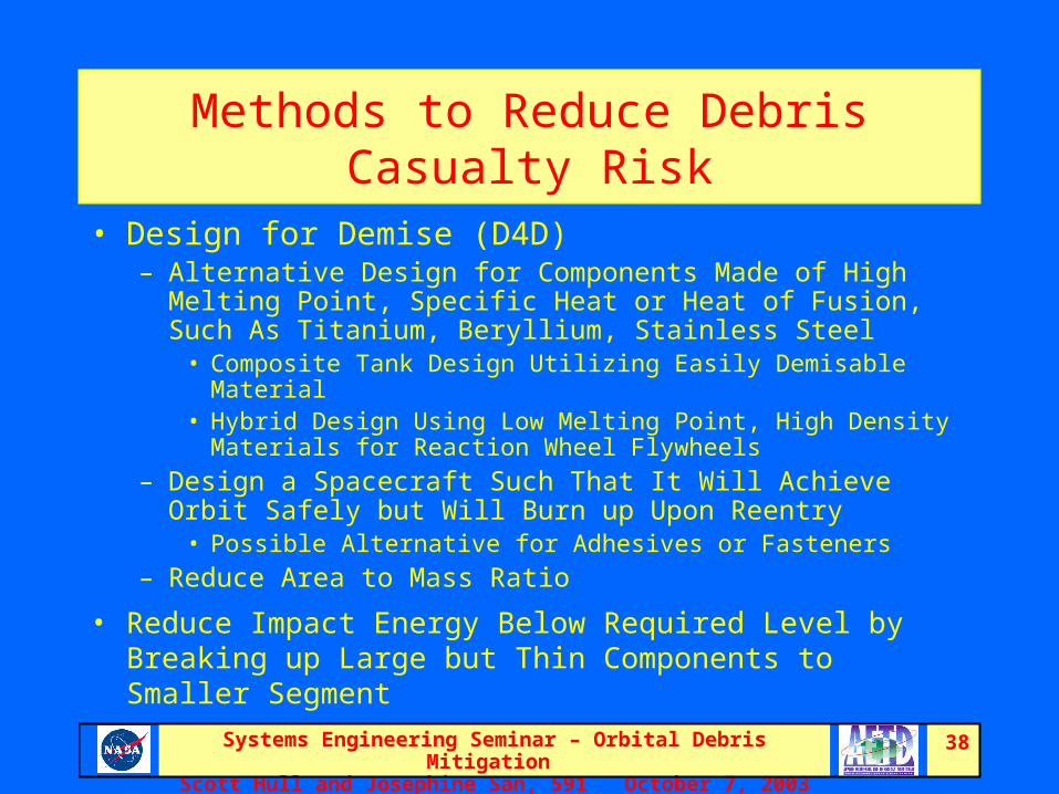
Methods to Reduce Debris Casualty Risk
• Design for Demise (D4D)– Alternative Design for Components Made of High Melting
Point, Specific Heat or Heat of Fusion, Such As Titanium, Beryllium, Stainless Steel
• Composite Tank Design Utilizing Easily Demisable Material• Hybrid Design Using Low Melting Point, High Density Materials
for Reaction Wheel Flywheels
– Design a Spacecraft Such That It Will Achieve Orbit Safely but Will Burn up Upon Reentry
• Possible Alternative for Adhesives or Fasteners
– Reduce Area to Mass Ratio
• Reduce Impact Energy Below Required Level by Breaking up Large but Thin Components to Smaller Segment

Systems Engineering Seminar – Orbital Debris Mitigation Scott Hull and Josephine San, 591 October 7, 2003
39
Controlled Reentry - Cost
• Material, Design and Development Costs– Full Cost for Hardware to Meet High Probability of Success
• Propulsion System• Structure to Support Propulsion System• ACS Components to Support Controlled Re-entry
– Incremental Cost for Hardware to Meet High Probability of Success Including Power, Communication, Thermal, and C&DH Systems
– Full Cost for Attitude Controller Design and Development Including Delta V Control Mode for Long Duration Burn, Delta H Mode to Achieve Low Perigee Control, and Mode Transitions
– Full Cost for Reentry Software, Including Fault Management for Controlled Re-entry System, Flight Software for ACS Reentry Controlled Algorithm, and Ground Software for Testing, Simulation, and Re-entry Operation Support
– Full Cost for Improved End-of-life Fuel Depletion Computation Method

Systems Engineering Seminar – Orbital Debris Mitigation Scott Hull and Josephine San, 591 October 7, 2003
40
Controlled Reentry – Cost (cont.)
– All Full Costs Will Become Incremental Cost for Missions which Require a Propulsion System for Orbit Maintenance
• More Propellant, Larger Tank, and Higher Force Level Thrusters
• ACS Components Sized to Support Controlled Reentry
• I & T Cost for Safe Disposal Segment– Incremental Cost for Missions Required Propulsion System
for Orbit Maintenance Already
• Operational cost– Managing and Planning– Implementation, Training, and Simulation
– Carrying Out Final Reentry
Systems Engineering Seminar – Orbital Debris Mitigation Scott Hull and Josephine San, 591 October 7, 2003
41
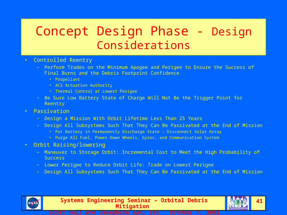
Concept Design Phase - Design Considerations
• Controlled Reentry– Perform Trades on the Minimum Apogee and Perigee to Ensure the Success of Final
Burns and the Debris Footprint Confidence• Propellant • ACS Actuation Authority • Thermal Control at Lowest Perigee
– Be Sure Low Battery State of Charge Will Not Be the Trigger Point for Reentry
• Passivation– Design a Mission With Orbit Lifetime Less Than 25 Years
– Design All Subsystems Such That They Can Be Passivated at the End of Mission• Put Battery in Permanently Discharge State – Disconnect Solar Array• Purge All Fuel, Power Down Wheels, Gyros, and Communication System
• Orbit Raising/lowering– Maneuver to Storage Orbit: Incremental Cost to Meet the High Probability of Success
– Lower Perigee to Reduce Orbit Life: Trade on Lowest Perigee
– Design All Subsystems Such That They Can Be Passivated at the End of Mission

Systems Engineering Seminar – Orbital Debris Mitigation Scott Hull and Josephine San, 591 October 7, 2003
42
Preliminary/Critical Design Phase – Design Considerations, Necessary Analysis and Planning
• Redo Orbital Debris Analysis and Reconsider Safe Disposal Method If Necessary
• Refine Design and Perform Analysis to Verify Design for Safe Disposal
• As a Good Practice, Outline a End-of-Mission Plan by PDR and Produce a Draft by CDR
• Controlled Reentry – Refine Propellant Budget and End-of-life Fuel Mass Estimation
Method– Design Delta V and Delta H Mode, and Lay Out Mode Transition
Sequence– Develop Failure Detection and Correction (FDC) Logic– Develop Failure Modes and Perform Failure Effect Analysis

Systems Engineering Seminar – Orbital Debris Mitigation Scott Hull and Josephine San, 591 October 7, 2003
43
Operation and End-of-Mission Phase –Implementation of Safe Disposal Plan
• Perform Orbital Debris Analysis if not Done Already• Evaluate Spacecraft Hardware and Software• Propose or Re-Evaluate Viable Safe Disposal Options • Perform Risk Analysis• Evaluate Ground and Network System Readiness • Complete End-of-mission Plan Including Nominal and
Contingence Plans and Procedures• Prepare for Reviews if Necessary• Implement Safe Disposal Plan at the End of Mission

Systems Engineering Seminar – Orbital Debris Mitigation Scott Hull and Josephine San, 591 October 7, 2003
44
End-of-Mission Planning• Management
– Manpower Estimation, Assign Roles and Responsibilities, Prepare for Anomaly Investigation
– External Interfaces Including Space Command, NIMA (Coast Guard, Airline), Public Affairs, HQ, ISS/JSC and State Department
– Disposition of Ground Hardware and Software
– Plan to Continue Reentry Prediction If Needed
– The First Two Items Are Especially Critical for Controlled Reentry
• Trigger Points– Nominal Trigger Point Around Which Safe Disposal Plan Is
Designed, E.G. Fuel Level
– Off Nominal Trigger Points With Different Criticality Level
– Constituent and Actions Associated With Each Trigger Point

Systems Engineering Seminar – Orbital Debris Mitigation Scott Hull and Josephine San, 591 October 7, 2003
45
End-of-Mission Planning (cont.)
• System Evaluation and Risk Analysis– Ground Based System Evaluation Including Ground
System and Network Support– Spacecraft State of Health Including Instrument, Bus
Hardware and Software– Assign Trigger Level to Each Critical Component– Perform Risk Analysis for Each Failure
• Documentation Management– Configuration Management for Procedures, Timelines – Final Engineering Report

Systems Engineering Seminar – Orbital Debris Mitigation Scott Hull and Josephine San, 591 October 7, 2003
46
Implementation of End-of-Mission Plan
• Nominal Plans, Procedures, and Timeline Script– Orbit Raising/lowering Option
• Maneuver Plan, Maneuver Plan Implementation Procedure, Procedure for Final Jettison of Propellant
• Plan to Coordinate Ground, Network and FDF Support• Plan and Procedure for Lowering the Orbit by Other Means• Sequence Plan to Shutdown Hardware, To Put Battery in Permanent
Discharge State• Timeline Scripts for on Consol Operation
– Passivation Option• Plan to Coordinate Ground, Network and FDF Support• Procedure for Final Jettison of Propellant If Needed• Sequence Plan to Shutdown Hardware, To Put Battery in Permanent
Discharge State• Timeline Scripts for on Console Operation

Systems Engineering Seminar – Orbital Debris Mitigation Scott Hull and Josephine San, 591 October 7, 2003
47
Implementation of End-of-Mission Plan (cont.)
• Nominal Plans, Procedures, and Timeline Script (Cont.)– Controlled Reentry Option
• Plan to Coordinate Ground, Network and FDF Support• Mission Design for Controlled Reentry Shall Be Simple
and Robust, It Shall Use the Spacecraft As Close to Its Original Design As Possible
• Some of the End Products From Mission Design Are Maneuver Plan, Operation Sequence Plan, Mode Transition Plan, Plan to Characterization Burns
• Implementation Procedures for All These Plans• Develop Burn Commit and Abort Criteria

Systems Engineering Seminar – Orbital Debris Mitigation Scott Hull and Josephine San, 591 October 7, 2003
48
End-of-Mission Planning (cont.)Implementation of End-of-Mission Plan
• Contingence Plans– Event Fault Tree and Probability of Success– Debris Field Error Analysis and Effective Delta V Reserve
Allocation– Contingency Handling Flow– Contingency Plans for Most Likely and Combination of Most
Likely Failures
• Training and Simulation Planning– Plans to Train Support Personnel– Plans to Verify Scripts, Procedures and Contingency Plans– Plans to Simulate Interaction Between Teams

Systems Engineering Seminar – Orbital Debris Mitigation Scott Hull and Josephine San, 591 October 7, 2003
49
Design for Demise (D4D) Examples
Scott Hull / 591
NASA/GSFC

Systems Engineering Seminar – Orbital Debris Mitigation Scott Hull and Josephine San, 591 October 7, 2003
50
Design for Demise (D4D)
• An effort to create alternate designs with the intent of ensuring complete demise during reentry– Generic designs for perennial survivors– Mission-specific designs for surviving components
• Methods– Different material– Multiple materials– Different shape– New technology
Systems Engineering Seminar – Orbital Debris Mitigation Scott Hull and Josephine San, 591 October 7, 2003
51
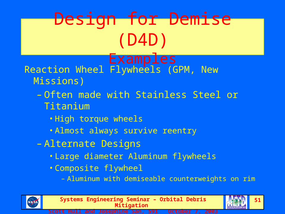
Design for Demise (D4D)Examples
Reaction Wheel Flywheels (GPM, New Missions)– Often made with Stainless Steel or Titanium
• High torque wheels• Almost always survive reentry
– Alternate Designs• Large diameter Aluminum flywheels• Composite flywheel
– Aluminum with demiseable counterweights on rim

Systems Engineering Seminar – Orbital Debris Mitigation Scott Hull and Josephine San, 591 October 7, 2003
52
Design for Demise (D4D)Examples
Propellant / Pressure Tanks (GPM, New Missions)– Most traditional tanks are made from Titanium or
Stainless Steel– As you can see, Titanium and Stainless Steel tanks
often survive!

Systems Engineering Seminar – Orbital Debris Mitigation Scott Hull and Josephine San, 591 October 7, 2003
53
Design for Demise (D4D)Examples
Propellant / Pressure Tanks - Alternate Designs• Aluminum Tanks• Composite Tanks
– Al, SS, or even Ti liner for hermeticity– Graphite composite overwrap for strength
• External Heat Sources– Passively initiated pyrotechnics– Burn to provide intense heat, not explode

Systems Engineering Seminar – Orbital Debris Mitigation Scott Hull and Josephine San, 591 October 7, 2003
54
Design for Demise (D4D)Examples
Batteries (GPM, New Missions)– Typical NiMH cells are pressure vessels
• Inconel, Nickel, or Stainless Steel• Result: Cells barely demise or survive
– Due to high quantity, DCA can be very large (~10 m2)
– Lithium Ion Batteries• Low pressure operation• Aluminum case• Result: Cells demise

Systems Engineering Seminar – Orbital Debris Mitigation Scott Hull and Josephine San, 591 October 7, 2003
55
Design for Demise (D4D)Examples
Instrument Attach Flexures (GLAST)– Original design
• 4 Titanium “boomerang” with flat plates as legs• Result: Flexures survived reentry
– DCA: 0.63 m2 each, 2.61 m2 total
– Modified design• Legs converted to square cross-section• Result: ORSAT simulation showed flexures
demise– DCA=0

Systems Engineering Seminar – Orbital Debris Mitigation Scott Hull and Josephine San, 591 October 7, 2003
56
Design for Demise (D4D)Examples
• Tungsten Converter Foils (GLAST)– Original design
• 1024 Thin flat plates ~4” square• Result: Foils survive with impact energy of 24 J• DCA: 0.47 m2 each, 484 m2 total
– Modified design• 2048 Thin flat plates ~4” x 2”• Result: Foils survive with impact energy of 12 J• Below the casualty threshold, DCA =0

Systems Engineering Seminar – Orbital Debris Mitigation Scott Hull and Josephine San, 591 October 7, 2003
57
Design for Demise (D4D)Examples
Optical Bench Struts (GLAST)– Original design
• 8 Titanium tubes• Good thermal isolation and CTE• Result: Survived reentry
– DCA: 0.47 m2 each, 3.75 m2 total
– Modified design• Material changed to graphite composite• Maintained thermal properties• Result: ORSAT simulation showed struts demise

Systems Engineering Seminar – Orbital Debris Mitigation Scott Hull and Josephine San, 591 October 7, 2003
58
Current Status (slide 1 of 2)
• Orbital Debris Colloquia – Most recent was 3/20/2002 at GSFC– Next colloquium is 11/4-5/2003 at JSC
• NPD 8710.3A– Updated and reissued 1/27/2003
• NSS 1740.14– Updates proposed by JSC– To be discussed 11/5/2003– Will be reissued as NS 8719.14

Systems Engineering Seminar – Orbital Debris Mitigation Scott Hull and Josephine San, 591 October 7, 2003
59
Current Status (slide 2 of 2)
• DAS Software– Current version is 1.5.3– Web interface is to be available soon to GSFC domains– Version 2.0 to be discussed 11/5/2003
• ORSAT Software– Current version is 5.8 (only at JSC)– GSFC has version 5.5
• Projects being supportedGLAST, TRMM, GPM, HST, SDO, SNOE, Swift, NPP, EXIST
• ReEntry Breakup Recorder (REBR)– Cooperative effort with Aerospace Corp– Will record temperature, accelometer, integrity data during actual
reentries

Systems Engineering Seminar – Orbital Debris Mitigation Scott Hull and Josephine San, 591 October 7, 2003
60
Mir Reentry