Systems Application Information...Harris Corporation Constellation LIST OF FIGURES LIST OF FIGURES...
112
Point-to-Point Digital Radio Constellation™ Systems Application Information next level solutions
Transcript of Systems Application Information...Harris Corporation Constellation LIST OF FIGURES LIST OF FIGURES...

Point-to-Point
Digital Radio
Constellation™
Systems
Application
Information
next level solutions


Constellation™Microwave Radio
SYSTEMS APPLICATION INFORMATIONJune 20, 2002
SAI-112874-E04

Copyright 2002, HARRIS CORPORATION. All rights reserved.Constellation, FarScan, GlobeStar, MegaStar, MicroStar, NetBoss, StarView, and VersaT1lity are
trademarks of Harris Corporation.All other brand or product names are trademarks of their respective companies or organizations.
HARRIS CORPORATIONMicrowave Communications Division
350 Twin Dolphin DriveRedwood Shores, CA 94065-1421http://www.microwave.harris.com
We’re ISO certified.
CO
NTEN
TS
CONTENTS
LIST OF FIGURES ................................................................V
LIST OF TABLES............................................................... VII
CHAPTER 1, GENERAL INFORMATION .................................. 1-1Introduction ................................................................................................ 1-1The Constellation Radio ................................................................................ 1-1Harris’ Proven Ability .................................................................................... 1-2Statement of Accuracy and Liability ................................................................ 1-2
CHAPTER 2, FREQUENCY PLANNING.................................... 2-1Frequency Bands ......................................................................................... 2-1Channel Assignments ................................................................................... 2-3
Canada.................................................................................................... 2-3Industry Canada, GL-34......................................................................... 2-3Industry Canada, SRSP-305.9 ................................................................ 2-3Industry Canada, SRSP-306.4 ................................................................ 2-4Industry Canada, SRSP-307.1 ................................................................ 2-5Industry Canada, SRSP-307.7 ................................................................ 2-6Industry Canada, SRSP-310.5 ................................................................ 2-7Industry Canada, SRSP-310.7 ................................................................ 2-8
International ............................................................................................ 2-8ITU-R 385-6 A4 .................................................................................... 2-8ITU-R 386-5 A3 .................................................................................... 2-9
U.S.A. ................................................................................................... 2-10FCC Part 101...................................................................................... 2-10
1+1 Frequency Selection ............................................................................ 2-161+1 Frequency Spacing for Hot-standby (HS) and Nonprotected (NP) Radios .. 2-161+1 Intermodulation Products for Multiple HS or NP Radios with Common Antenna Feedline ................................................................................................ 2-16
Regulatory Information Licensed Part 101 Service .......................................... 2-17
CHAPTER 3, CONSTELLATION RADIO CONFIGURATIONS .......... 3-1The Constellation Radio ................................................................................ 3-1
Narrow/Medium Capacity Radio .................................................................. 3-1High Capacity Radio .................................................................................. 3-2Upgradability............................................................................................ 3-2
3xDS3 and 155 Configurations ...................................................................... 3-2Network Management and Control .................................................................. 3-3
Network Management Interfaces................................................................. 3-3Craft Interface Tool ................................................................................... 3-3
Harris Corporation Constellation™

ii
External Alarm/Control .............................................................................. 3-3Antenna Coupling Unit (ACU) ......................................................................... 3-3Multiplexer Configurations ............................................................................. 3-4Constellation DS3 Interface Configurations ...................................................... 3-5Constellation 3xDS3 Interface Configurations .................................................. 3-8Radio Synchronization Configuration ............................................................. 3-10
CHAPTER 4, TECHNICAL SPECIFICATIONS.............................4-1Power Requirements (Top of Rack) ................................................................. 4-1
Power Consumption .................................................................................. 4-1Power Source ........................................................................................... 4-2
Power Source Voltage............................................................................ 4-2Power Source Noise .............................................................................. 4-2
Built-in Radio Fuse Panel ........................................................................... 4-2Circuit Breakers........................................................................................ 4-3
RF Performance Specifications ....................................................................... 4-3Transmitter ................................................................................................. 4-7
Frequency Stability ................................................................................... 4-7Unwanted (Out-of-Band and Spurious) Emissions.......................................... 4-7
Receiver ..................................................................................................... 4-8General Specifications ............................................................................... 4-8Receiver Overload* ................................................................................... 4-8Dispersive Fade Margin (DFM) .................................................................... 4-9Signal Acquisition Time.............................................................................. 4-9Auto-DADE .............................................................................................. 4-9
Tributary Interface ..................................................................................... 4-10Tributary Signal Characteristics ................................................................ 4-10Tributary Jitter ....................................................................................... 4-10Tributary Specification Compliance............................................................ 4-10
Signal Processing ....................................................................................... 4-11Equipment Transmission Delay Time ......................................................... 4-11Modulation............................................................................................. 4-11Forward Error Correction (FEC)................................................................. 4-12Intermediate Frequency Signal ................................................................. 4-12
Protection Switching ................................................................................... 4-121+1 Transmitter and Receiver Switching.................................................... 4-12
Hot-Standby Transmitter Switching ....................................................... 4-12Reverse Path Protection....................................................................... 4-12HS Receiver Switching......................................................................... 4-13Space Diversity Receiver Switching ....................................................... 4-13Receiver Switching Criteria................................................................... 4-13Uncorrected BER (UBER) Alarm............................................................. 4-13Received Signal Level (RSL) Alarm ........................................................ 4-13
Maintenance .......................................................................................... 4-13Manual Switch-over ................................................................................ 4-131+1 Switching Times............................................................................... 4-14
Supervisory Interfaces ............................................................................... 4-14Network Management Interface ................................................................ 4-14
Alarms ..................................................................................................... 4-15Alarm Indication Signal (AIS) ................................................................... 4-15
Constellation™ 2002 June 20

Contents iii CO
NTEN
TS
Radio Alarm LED Indicators ...................................................................... 4-15Site Status Inputs and Control Outputs ...................................................... 4-15
Alarm List for Relay Output .................................................................. 4-16Relay Specifications ............................................................................ 4-16
Environmental Specifications ....................................................................... 4-17Electromagnetic Emissions ....................................................................... 4-17Conducted Emissions............................................................................... 4-17Ambient Temperature, Humidity, and Altitude............................................. 4-17Earthquake, Shock, and Vibration ............................................................. 4-17
Test specification ................................................................................ 4-17Rack Specifications ............................................................................. 4-17
Mechanical Dimensions ............................................................................... 4-18EIA Rack ............................................................................................... 4-18Constellation Radio ................................................................................. 4-18
Weights (Typical) ....................................................................................... 4-18
CHAPTER 5, SYSTEM INTERCONNECT AND CONFIGURATION ..... 5-1System Interconnection ................................................................................ 5-1
Orderwire Interconnection.......................................................................... 5-1Four-Wire VF Orderwire Interface................................................................ 5-4Two-Wire VF Orderwire Interface ................................................................ 5-5
Address ............................................................................................... 5-5Data Orderwire Interface ........................................................................... 5-5SCAN Equipment Interconnection................................................................ 5-7
CHAPTER 6, ANTENNA COUPLING UNIT (ACU)..................... 6-1ACU Waveguide Flanges ............................................................................... 6-1ACU Configuration and Mechanical Drawings .................................................... 6-2
Available Configurations ............................................................................ 6-2List of ACU Mechanical Drawings................................................................. 6-3ACU Mechanical Drawings .......................................................................... 6-3
ACU Port Configurations ................................................................................ 6-9
CHAPTER 7, PERFORMANCE CURVES ................................... 7-1Performance Curves ..................................................................................... 7-1Threshold-to-Interference (T/I) Ratios ............................................................ 7-2
Overview ................................................................................................. 7-2Like Signal T/I Ratio.................................................................................. 7-3T/I Curves ............................................................................................... 7-4
Receiver Signal-to-Noise Characteristics ....................................................... 7-11BER versus C/N Curve ............................................................................. 7-11
BER versus RSL Dynamic Range .................................................................. 7-15Jitter Characteristics ................................................................................... 7-16
APPENDIX A, RACK PROFILES ...........................................A-119-inch Rack Frame ..................................................................................... A-1
Harris Corporation Constellation™

iv
APPENDIX B, GLOSSARY .................................................. B-1
APPENDIX I, INDEX......................................................... I-1
Constellation™ 2002 June 20

LIS
T O
F F
IGU
RES
LIST OF FIGURESFigure 3-1: Multiplexer configuration for a radio terminal ...................................... 3-4
Figure 3-2: Multiplexer configuration for a radio-to-radio repeater .......................... 3-4
Figure 3-3: Multiplexer configuration for a dual radio terminal ............................... 3-5
Figure 3-4: Constellation radio terminal, DS3 interface ......................................... 3-5
Figure 3-5: 28 DS1 to DS3 application ................................................................ 3-6
Figure 3-6: 28 DS1 to repeater to DS3 application ............................................... 3-7
Figure 3-7: 3xDS3 to 3xDS3 configuration .......................................................... 3-8
Figure 3-8: 3xDS3 to 3xDS3 back-to-back terminals (repeater) ............................. 3-8
Figure 3-9: 2xDS3 + 28DS1 configuration ........................................................... 3-9
Figure 3-10: 2xDS3 + 28DS1 back-to-back terminals (repeater) ............................ 3-9
Figure 4-1: Battery voltage noise limit ................................................................ 4-2
Figure 6-1: ACU, nonprotected (top view), mechanical drawing .............................. 6-3
Figure 6-2: ACU, nonprotected (front view), mechanical drawing ............................ 6-4
Figure 6-3: ACU, hot-standby (top view), mechanical drawing ............................... 6-4
Figure 6-4: ACU, hot-standby (front view), mechanical drawing ............................. 6-5
Figure 6-5: ACU, hot-standby Transmitters, space-diversity Receivers (top view), mechanical drawing ......................................................................................... 6-5
Figure 6-6: ACU, hot-standby Transmitters, space-diversity Receivers (front view), mechanical drawing ......................................................................................... 6-6
Figure 6-7: ACU, hot-standby/frequency-diversity, 2-antenna (T/R, T/R) (top view), mechanical drawing ......................................................................................... 6-6
Figure 6-8: ACU, hot-standby/frequency-diversity 2-antenna (T/R, T/R) (front view), mechanical drawing ......................................................................................... 6-7
Figure 6-9: ACU, repeater/dual terminal, mechanical drawing ................................ 6-8
Figure 7-1: Typical threshold-to-interference (T/I) curve (6 GHz and 7/8 GHz, 8 DS1) ........................................................................................................... 7-4
Figure 7-2: Typical threshold-to-interference (T/I) curve (10/11 GHz, 8 DS1) .......... 7-5
Figure 7-3: Typical threshold-to-interference (T/I) curve (6 GHz and 7/8 GHz, 16 DS1) ......................................................................................................... 7-6
Figure 7-4: Typical threshold-to-interference (T/I) curve (10/11 GHz, 16 DS1) ........ 7-7
Figure 7-5: Typical threshold-to-interference (T/I) curve (6 GHz and 7/8 GHz, 28 DS1/DS3) .................................................................................................. 7-8
Figure 7-6: Typical threshold-to-interference (T/I) curve (10/11 GHz, 28 DS1/DS3) . 7-9
Harris Corporation Constellation™

vi
Figure 7-7: Typical threshold-to-interference (T/I) curve (6, 7/8, 10/11 GHz, 155 Mbit/s, 128 TCM) ..................................................................................... 7-10
Figure 7-8: Typical BER versus C/N curve (8 DS1) ............................................. 7-11
Figure 7-9: Typical BER versus C/N curve (16 DS1) ............................................ 7-12
Figure 7-10: Typical BER versus C/N curve (28 DS1/DS3) ................................... 7-13
Figure 7-11: Typical BER versus C/N curve (Constellation 155) ............................ 7-14
Figure 7-12: Typical BER versus RSL curve ....................................................... 7-15
Figure 7-13: Typical DS1 jitter transfer curve .................................................... 7-16
Figure 7-14: Typical DS1 input jitter tolerance curve .......................................... 7-16
Figure 7-15: Typical DS3 jitter transfer curve .................................................... 7-17
Figure 7-16: Typical DS3 input jitter tolerance curve .......................................... 7-17
Figure A-1: EIA 19-inch rack frame and pedestal detail (top view) .......................... A-1
Figure A-2: EIA 19-inch rack frame and pedestal detail ......................................... A-2
Constellation™ 2002 June 20
LIS
T O
F T
AB
LES
LIST OF TABLESTable 2-1: Frequency band, Canada .................................................................... 2-1
Table 2-2: Frequency band, International............................................................. 2-2
Table 2-3: Frequency band, U.S.A....................................................................... 2-2
Table 2-4: 5850 MHz to 5915 MHz (Industry Canada, GL-34) ................................. 2-3
Table 2-5: 5915 MHz to 6425 MHz (Industry Canada SRSP-305.9) .......................... 2-3
Table 2-6: 6425 MHz to 6930 MHz (Industry Canada, SRSP-306.4) ......................... 2-4
Table 2-7: 7125 MHz to 7725 MHz (Industry Canada, SRSP-307.1) ......................... 2-5
Table 2-8: 7725 MHz to 8275 MHz (Industry Canada, SRSP-307.7) ......................... 2-6
Table 2-9: 10550 MHz to 10595 MHz and 10615 MHz to 10660 MHz (Industry Canada, SRSP-310.5) .................................................................................................... 2-7
Table 2-10: 10700 MHz to 11700 MHz (Industry Canada, SRSP-310.7) .................... 2-8
Table 2-11: 7425 MHz to 7900 MHz (ITU-R 385-6 A4) ........................................... 2-8
Table 2-12: 8275 MHz to 8500 MHz (ITU-R 386-5 A3) ........................................... 2-9
Table 2-13: 5925 MHz to 6425 MHz (FCC Part 101)............................................. 2-10
Table 2-14: 6525 MHz to 6875 MHz (FCC Part 101)............................................. 2-11
Table 2-15: 10550 MHz to 10680 MHz (FCC Part 101) ......................................... 2-12
Table 2-16: 10700 MHz to 11700 MHz (FCC Part 101) ......................................... 2-13
Table 2-17: 10700 MHz to 11700 MHz (FCC Part 101) ......................................... 2-14
Table 2-18: 10700 MHz to 11700 MHz (FCC Part 101) ......................................... 2-15
Table 2-19: Frequency spacing ......................................................................... 2-16
Table 2-20: Regulatory information licensed Part 101 service ............................... 2-17
Table 4-1: Recommended circuit breaker sizes ..................................................... 4-3
Table 4-2: Additional ACU loss............................................................................ 4-3
Table 4-3: RF performance specifications ............................................................. 4-4
Table 4-4: DFM* with delay of 6.3 ns .................................................................. 4-9
Table 4-5: Re-acquisition budget for hardware failures........................................... 4-9
Table 4-6: Network management interface......................................................... 4-14
Table 4-7: Relay specifications ......................................................................... 4-16
Table 5-1: Orderwire interconnection .................................................................. 5-2
Table 5-2: Four-wire VF Orderwire input specifications........................................... 5-4
Table 5-3: Four-wire VF ports performance specifications ....................................... 5-4
Table 5-4: Ringing generator specifications .......................................................... 5-4
Table 5-5: Output voltage range (with 7k ohm load) ............................................. 5-6
Table 5-6: Input voltage range ........................................................................... 5-6
Table 5-7: SCAN equipment interconnection......................................................... 5-7
Harris Corporation Constellation™
viii
Table 6-1: Standard flange specifications ............................................................. 6-1
Table 6-2: Spacer adapter height, standard (other interfaces available) ................... 6-1
Table 6-3: Available ACU configurations* ............................................................. 6-2
Table 6-4: X dimension from floor, ACU, repeater/dual terminal.............................. 6-8
Table 6-5: ACU port configurations ..................................................................... 6-9
Table 7-1: Like signal T/I for 6 and 7/8 GHz......................................................... 7-3
Table 7-2: Like signal T/I for 10/11 GHz .............................................................. 7-3
Constellation™ 2002 June 20

GEN
ER
AL
INFO
RM
ATIO
N
C H A P T E R
1GENERAL INFORMATION
Introduction
The Systems Application Information (SAI) provides technical information required for determining communication system design, site layout, and interface equipment compatibility. This information will assist in the configuration of Constellation digital microwave radio equipment.
The Constellation Radio
Constellation radios make up one of Harris’ families of high-quality transmission equipment. The radios feature multiple capacities and frequency bands, upgrade capability, high commonality of spares, and are compatible with existing systems and equipment.
Constellation radios offer advanced technology and efficient engineering that allow network operators to focus on serving customers, expanding their network, and increasing revenue and profitability.
Constellation radios offer high levels of reliability that are required in rugged or congested environments. The radios make use of the following:
• Fully digital adaptive time domain equalizer (ATDE)• Forward error correction (FEC)• Anticipatory errorless receiver switching• Automatic transmitter power control (ATPC) can be provisioned to be
enabled, disabled with transmitter set to high power, or disabled with transmitter set to low power.
Harris Corporation Constellation™

1-2
The Constellation radio’s self-aligning operation eliminates the need for most of the test equipment required by older-generation, low-, medium-, to high-capacity microwave radios. The operation includes the following:
• Remote inventory management capability• SCAN (system control and alarm network) communication bus for
remote diagnostics• SNMP (Simple Network Management Protocol) and FarScan network
management interfaces• Self-healing architecture• Self-adaptive circuitry• Automatic calibration of replacement circuit packs (excludes the
Transmitter and Receiver)• Remote software download
Harris’ Proven Ability
Harris has a reputation as a worldwide supplier of cost-effective communication solutions for small and large networks. Many types of businesses, including telephone companies, government agencies, educational institutions, broadcast stations, pipelines, railroads, transportation agencies, gas and electric utilities, public safety agencies, wireless telephone providers, hospitals, and other organizations with communication networks in the United States, Canada, and over 100 other countries are satisfied Harris customers.
Statement of Accuracy and Liability
Harris reserves the right to make changes in circuit design, specifications, services, and other information at any time without prior notice. Harris does not assume responsibility or liability arising out of the application or use of any product or service described herein, except as expressly agreed to in writing by Harris Corporation.
Constellation™ 2002 June 20

FR
EQ
UEN
CY
P
LA
NN
ING
C H A P T E R
2FREQUENCY PLANNING
Frequency Bands
Constellation radios are available in 6, 7, 8, 10, and 11 GHz frequency bands. The following tables show the frequency bands for the various countries.
Table 2-1: Frequency band, Canada
Frequency Band (MHz)
Channel Bandwidth (MHz)
In Compliance with Industry Canada
5850 to 5915 3.55.2510
GL-34a
a. These systems are not included in SP 305.8. Refer to GL-34 for details.
5915 to 6425 29.65 SRSP-305.9
6425 to 6930 1030
SRSP-306.4
7125 to 7725 3.7551030
RSP-307.1
7725 to 8275 1030
SRSP-307.7
10550 to 10680 3.755
SRSP-310.5
10700 to 11700b
b. 11,650 to 11,700 MHz is on reserve in Canada.
40 SRSP-310.7
Harris Corporation Constellation™

2-2
Table 2-2: Frequency band, International
Frequency Band (MHz)
Channel Bandwidth(MHz)
In compliancewith ITU-R
7425 to 79008275 to 8500
1414
Rec. 385-6 A4Rec. 386-5 A3
Table 2-3: Frequency band, U.S.A.
Frequency Band (MHz)
Channel Bandwidth (MHz)
In Compliance With
5925 to 6425 3.7551030
FCC Part 101
6525 to 6875 3.75510
FCC Part 101
7125 to 8500 3.75510
NTIA (US Government)
10550 to 10680 3.755
FCC Part 101
10700 to 11700 3.7551030
FCC Part 101
Constellation™ 2002 June 20
Frequency Planning 2-3
FR
EQ
UEN
CY
P
LA
NN
ING
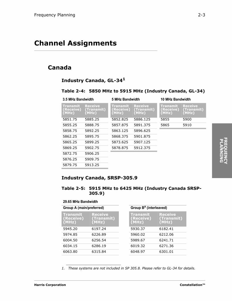
Channel Assignments
Canada
Industry Canada, GL-341
Industry Canada, SRSP-305.9
1. These systems are not included in SP 305.8. Please refer to GL-34 for details.
Table 2-4: 5850 MHz to 5915 MHz (Industry Canada, GL-34)
3.5 MHz Bandwidth 5 MHz Bandwidth 10 MHz BandwidthTransmit (Receive) (MHz)
Receive (Transmit) (MHz)
Transmit (Receive) (MHz)
Receive (Transmit) (MHz)
Transmit (Receive) (MHz)
Receive (Transmit) (MHz)
5851.75 5885.25 5852.825 5886.125 5855 5900
5855.25 5888.75 5857.875 5891.375 5865 5910
5858.75 5892.25 5863.125 5896.625
5862.25 5895.75 5868.375 5901.875
5865.25 5899.25 5873.625 5907.125
5869.25 5902.75 5878.875 5912.375
5872.75 5906.25
5876.25 5909.75
5879.75 5913.25
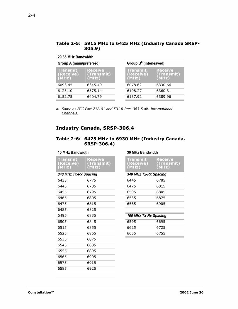
Table 2-5: 5915 MHz to 6425 MHz (Industry Canada SRSP-305.9)
29.65 MHz BandwidthGroup A (main/preferred) Group Ba (interleaved)
Transmit (Receive) (MHz)
Receive (Transmit) (MHz)
Transmit (Receive) (MHz)
Receive (Transmit) (MHz)
5945.20 6197.24 5930.37 6182.41
5974.85 6226.89 5960.02 6212.06
6004.50 6256.54 5989.67 6241.71
6034.15 6286.19 6019.32 6271.36
6063.80 6315.84 6048.97 6301.01
Harris Corporation Constellation™
2-4
Industry Canada, SRSP-306.4
6093.45 6345.49 6078.62 6330.66
6123.10 6375.14 6108.27 6360.31
6152.75 6404.79 6137.92 6389.96
a. Same as FCC Part 21/101 and ITU-R Rec. 383-5 alt. International Channels.
Table 2-6: 6425 MHz to 6930 MHz (Industry Canada, SRSP-306.4)
10 MHz Bandwidth 30 MHz Bandwidth
Transmit (Receive) (MHz)
Receive (Transmit) (MHz)
Transmit (Receive) (MHz)
Receive (Transmit) (MHz)
340 MHz Tx-Rx Spacing 340 MHz Tx-Rx Spacing6435 6775 6445 6785
6445 6785 6475 6815
6455 6795 6505 6845
6465 6805 6535 6875
6475 6815 6565 6905
6485 6825
6495 6835 100 MHz Tx-Rx Spacing6505 6845 6595 6695
6515 6855 6625 6725
6525 6865 6655 6755
6535 6875
6545 6885
6555 6895
6565 6905
6575 6915
6585 6925
Table 2-5: 5915 MHz to 6425 MHz (Industry Canada SRSP-305.9)
29.65 MHz BandwidthGroup A (main/preferred) Group Ba (interleaved)
Transmit (Receive) (MHz)
Receive (Transmit) (MHz)
Transmit (Receive) (MHz)
Receive (Transmit) (MHz)
Constellation™ 2002 June 20
Frequency Planning 2-5
FR
EQ
UEN
CY
P
LA
NN
ING
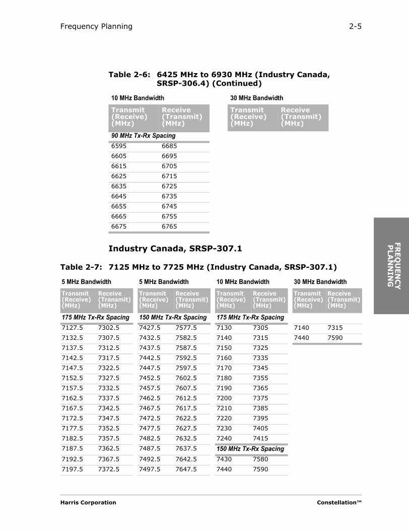
Industry Canada, SRSP-307.1
90 MHz Tx-Rx Spacing6595 6685
6605 6695
6615 6705
6625 6715
6635 6725
6645 6735
6655 6745
6665 6755
6675 6765
Table 2-6: 6425 MHz to 6930 MHz (Industry Canada, SRSP-306.4) (Continued)
10 MHz Bandwidth 30 MHz Bandwidth
Transmit (Receive) (MHz)
Receive (Transmit) (MHz)
Transmit (Receive) (MHz)
Receive (Transmit) (MHz)
Table 2-7: 7125 MHz to 7725 MHz (Industry Canada, SRSP-307.1)
5 MHz Bandwidth 5 MHz Bandwidth 10 MHz Bandwidth 30 MHz BandwidthTransmit (Receive) (MHz)
Receive (Transmit) (MHz)
Transmit (Receive) (MHz)
Receive (Transmit) (MHz)
Transmit (Receive) (MHz)
Receive (Transmit) (MHz)
Transmit (Receive) (MHz)
Receive (Transmit) (MHz)
175 MHz Tx-Rx Spacing 150 MHz Tx-Rx Spacing 175 MHz Tx-Rx Spacing7127.5 7302.5 7427.5 7577.5 7130 7305 7140 7315
7132.5 7307.5 7432.5 7582.5 7140 7315 7440 7590
7137.5 7312.5 7437.5 7587.5 7150 7325
7142.5 7317.5 7442.5 7592.5 7160 7335
7147.5 7322.5 7447.5 7597.5 7170 7345
7152.5 7327.5 7452.5 7602.5 7180 7355
7157.5 7332.5 7457.5 7607.5 7190 7365
7162.5 7337.5 7462.5 7612.5 7200 7375
7167.5 7342.5 7467.5 7617.5 7210 7385
7172.5 7347.5 7472.5 7622.5 7220 7395
7177.5 7352.5 7477.5 7627.5 7230 7405
7182.5 7357.5 7482.5 7632.5 7240 7415
7187.5 7362.5 7487.5 7637.5 150 MHz Tx-Rx Spacing7192.5 7367.5 7492.5 7642.5 7430 7580
7197.5 7372.5 7497.5 7647.5 7440 7590
Harris Corporation Constellation™

2-6
Industry Canada, SRSP-307.7
7202.5 7377.5 7502.5 7652.5 7450 7600
7207.5 7382.5 7507.5 7657.5 7460 7610
7212.5 7387.5 7512.5 7662.5 7470 7620
7217.5 7392.5 7517.5 7667.5 7480 7630
7222.5 7397.5 7522.5 7672.5 7490 7640
7227.5 7402.5 7527.5 7677.5 7500 7650
7232.5 7407.5 7532.5 7682.5 7510 7660
7237.5 7412.5 7537.5 7687.5 7520 7670
7242.5 7417.5 7542.5 7692.5 7530 7680
7247.5 7422.5 7547.5 7697.5 7540 7690
7552.5 7702.5 7550 7700
7557.5 7707.5 7560 7710
7562.5 7712.5 7570 7720
7567.5 7717.5
7572.5 7722.5
Table 2-7: 7125 MHz to 7725 MHz (Industry Canada, SRSP-307.1)
5 MHz Bandwidth 5 MHz Bandwidth 10 MHz Bandwidth 30 MHz BandwidthTransmit (Receive) (MHz)
Receive (Transmit) (MHz)
Transmit (Receive) (MHz)
Receive (Transmit) (MHz)
Transmit (Receive) (MHz)
Receive (Transmit) (MHz)
Transmit (Receive) (MHz)
Receive (Transmit) (MHz)
Table 2-8: 7725 MHz to 8275 MHz (Industry Canada, SRSP-307.7)
10 MHz Bandwidth 30 MHz Bandwidth
Transmit (Receive) (MHz)
Receive (Transmit) (MHz)
Transmit (Receive) (MHz)
Receive (Transmit) (MHz)
7730 8030 7740 8040
7740 8040 7770 8070
7750 8050 7800 8100
7760 8060 7830 8130
7770 8070 7860 8160
7780 8080 7890 8190
7790 8090 7920 8220
7800 8100 7950 8250
7810 8110
7820 8120
7830 8130
Constellation™ 2002 June 20

Frequency Planning 2-7
FR
EQ
UEN
CY
P
LA
NN
ING
Industry Canada, SRSP-310.5
7840 8140
7850 8150
7860 8160
7870 8170
7880 8180
7890 8190
7900 8200
7910 8210
7920 8220
7930 8230
7940 8240
7950 8250
7960 8260
7970 8270
Table 2-9: 10550 MHz to 10595 MHz and 10615 MHz to 10660 MHz (Industry Canada, SRSP-310.5)
5 MHz Bandwidth
Transmit (Receive) (MHz)
Receive (Transmit) (MHz)
10552.5 10617.5
10557.5 10622.5
10562.5 10627.5
10567.5 10632.5
10572.5 10637.5
10577.5 10642.5
10582.5 10647.5
10587.5 10652.5
10592.5 10657.5
Table 2-8: 7725 MHz to 8275 MHz (Industry Canada, SRSP-307.7) (Continued)
10 MHz Bandwidth 30 MHz Bandwidth
Transmit (Receive) (MHz)
Receive (Transmit) (MHz)
Transmit (Receive) (MHz)
Receive (Transmit) (MHz)
Harris Corporation Constellation™

2-8
Industry Canada, SRSP-310.7
International
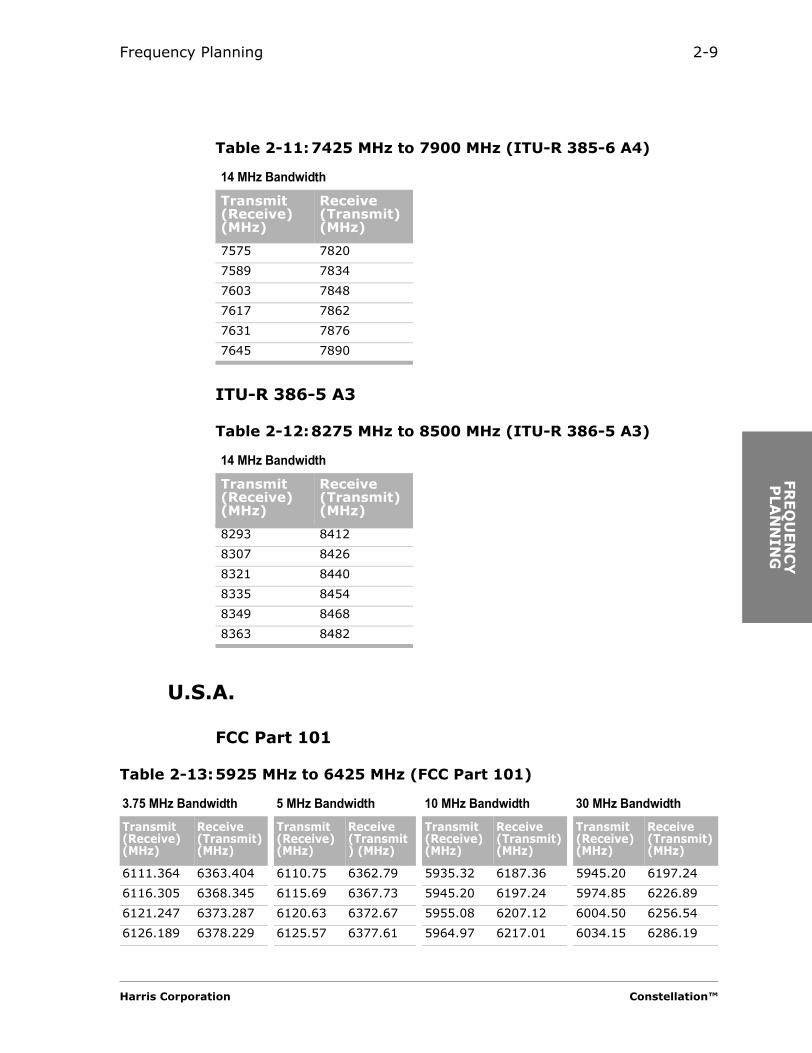
ITU-R 385-6 A4
Table 2-10:10700 MHz to 11700 MHz (Industry Canada, SRSP-310.7)
40 MHz Bandwidth
Transmit (Receive) (MHz)
Receive (Transmit) (MHz)
10735 11225
10775 11265
10815 11305
10855 11345
10895 11385
10935 11425
10975 11465
11015 11505
11055 11545
11095 11585
11135 11625
Table 2-11:7425 MHz to 7900 MHz (ITU-R 385-6 A4)
14 MHz Bandwidth
Transmit (Receive) (MHz)
Receive (Transmit) (MHz)
7435 7680
7449 7694
7463 7708
7477 7722
7491 7736
7505 7750
7519 7764
7533 7778
7547 7792
7561 7806
Constellation™ 2002 June 20
Frequency Planning 2-9
FR
EQ
UEN
CY
P
LA
NN
ING
ITU-R 386-5 A3
U.S.A.
FCC Part 101
7575 7820
7589 7834
7603 7848
7617 7862
7631 7876
7645 7890
Table 2-12:8275 MHz to 8500 MHz (ITU-R 386-5 A3)
14 MHz Bandwidth
Transmit (Receive) (MHz)
Receive (Transmit) (MHz)
8293 8412
8307 8426
8321 8440
8335 8454
8349 8468
8363 8482
Table 2-11:7425 MHz to 7900 MHz (ITU-R 385-6 A4)
14 MHz Bandwidth
Transmit (Receive) (MHz)
Receive (Transmit) (MHz)
Table 2-13:5925 MHz to 6425 MHz (FCC Part 101)
3.75 MHz Bandwidth 5 MHz Bandwidth 10 MHz Bandwidth 30 MHz BandwidthTransmit (Receive) (MHz)
Receive (Transmit) (MHz)
Transmit (Receive) (MHz)
Receive (Transmit) (MHz)
Transmit (Receive) (MHz)
Receive (Transmit) (MHz)
Transmit (Receive) (MHz)
Receive (Transmit) (MHz)
6111.364 6363.404 6110.75 6362.79 5935.32 6187.36 5945.20 6197.24
6116.305 6368.345 6115.69 6367.73 5945.20 6197.24 5974.85 6226.89
6121.247 6373.287 6120.63 6372.67 5955.08 6207.12 6004.50 6256.54
6126.189 6378.229 6125.57 6377.61 5964.97 6217.01 6034.15 6286.19
Harris Corporation Constellation™

2-10
6131.130 6383.170 6130.51 6382.55 5974.85 6226.89 6063.80 6315.84
6136.072 6388.112 6135.45 6387.49 5984.73 6236.77 6093.45 6345.49
6141.014 6393.054 6140.40 6392.44 5994.62 6246.66 6123.10b 6375.14b
6145.955 6397.995 6145.34 6397.38 6004.50 6256.54 6152.75b 6404.79b
6150.897 6402.937 6150.28 6402.32 6014.38 6266.42
6155.839 6407.879 6155.22 6407.26 6024.27 6276.31
6160.780 6412.820 6160.16 6412.20 6034.15 6286.19
6165.722 6417.762 6165.10 6417.14 6044.03 6296.07
6175.000a n/a 6053.92 6305.96
6063.80 6315.84
6073.68 6325.72
6083.57 6335.61
6093.45 6345.49
6103.33 6355.37
6113.22b 6365.26b
6123.10b 6375.14b
6132.98b 6385.02b
6142.87b 6394.91b
6152.75b 6404.79b
6162.63b 6414.67b
a. This frequency may be assigned for unpaired use.
b. Alternate channels. These channels are set aside for narrow bandwidth systems and should be used only if all other channels are blocked.
Table 2-13:5925 MHz to 6425 MHz (FCC Part 101) (Continued)
3.75 MHz Bandwidth 5 MHz Bandwidth 10 MHz Bandwidth 30 MHz BandwidthTransmit (Receive) (MHz)
Receive (Transmit) (MHz)
Transmit (Receive) (MHz)
Receive (Transmit) (MHz)
Transmit (Receive) (MHz)
Receive (Transmit) (MHz)
Transmit (Receive) (MHz)
Receive (Transmit) (MHz)
Constellation™ 2002 June 20

Frequency Planning 2-11
FR
EQ
UEN
CY
P
LA
NN
ING
Table 2-14:6525 MHz to 6875 MHz (FCC Part 101)
3.75 MHz Bandwidth 5 MHz Bandwidth 10 MHz BandwidthTransmit (Receive) (MHz)
Receive (Transmit) (MHz)
Transmit (Receive) (MHz)
Receive (Transmit) (MHz)
Transmit (Receive) (MHz)
Receive (Transmit) (MHz)
6545.625a
a. These frequencies may be assigned for unpaired use.
6715.625a 6545a 6715a 6545 67156550.625 6730.625 6550 6730 6555 67256555.625a 6725.625a 6555a 6725a 6565 67356560.625 6740.625 6560 6740 6585 67456565.625 6735.625 6565 6735 6595 67556585.625 6745.625 6585 6745 6605 67656590.625 6750.625 6590 6750 6615 67756595.625 6755.625 6595 6755 6625 67856600.625 6760.625 6600 6760 6635 67956605.625 6765.625 6605 6765 6645 68056610.625 6770.625 6610 6770 6655 68156615.625 6775.625 6615 6775 6665 68256620.625 6780.625 6620 6780 6675 68356625.625 6785.625 6625 6785 6685 68456630.625 6790.625 6630 6790 6695 68556635.625 6795.625 6635 6795 6705 68656640.625 6800.625 6640 6800 6535b
b. Available only for emergency restoration, maintenance bypass, or other temporary fixed purposes. Such uses are authorized on a noninterference basis to other freqencies in this band. Interference analysis required by § 101.105 does not apply to this frequency pair.
6575b
6645.625 6805.625 6645 68056650.625 6810.625 6650 68106655.625 6815.625 6655 68156660.625 6820.625 6660 68206665.625 6825.625 6665 68256670.625 6830.625 6670 68306675.625 6835.625 6675 68356680.625 6840.625 6680 68406685.625 6845.625 6685 68456690.625 6850.625 6690 68506695.625 6855.625 6695 68556700.625 6860.625 6700 68606705.625 6865.625 6705 68656710.625a 6720.625a 6710a 6720a
Harris Corporation Constellation™

2-12
Table 2-15:10550 MHz to 10680 MHz (FCC Part 101)
3.75 MHz Bandwidth 5 MHz Bandwidth
Transmit (Receive) (MHz)
Receive (Transmit) (MHz)
Transmit (Receive) (MHz)
Receive (Transmit) (MHz)
10553.125 10618.125 10552.5 10617.5
10558.125 10623.125 10557.5 10622.5
10563.125 10628.125 10562.5 10627.5
10568.125 10633.125 10567.5a
a. These frequencies are also available for DEMS stations licensed, in operation, or applied for prior to July 15, 1993.
10632.5a
10573.125 10638.125 10572.5a 10637.5a
10578.125 10643.125 10577.5a 10642.5a
10583.125 10648.125 10582.5a 10647.5a
10588.125 10653.125 10587.5 10652.5
10593.125 10658.125 10592.5 10657.5
10598.125 10663.125 10597.5 10662.5
10603.125 10668.125 10602.5 10667.5
Constellation™ 2002 June 20

Frequency Planning 2-13
FR
EQ
UEN
CY
P
LA
NN
ING
Table 2-16:10700 MHz to 11700 MHz (FCC Part 101)
3.75 MHz Bandwidth 5 MHz Bandwidth
Transmit (Receive) (MHz)
Receive (Transmit) (MHz)
Transmit (Receive) (MHz)
Receive (Transmit) (MHz)
11133.125 11623.125 11132.5 11622.5
11138.125 11628.125 11137.5 11627.5
11143.125 11633.125 11142.5 11632.5
11148.125 11638.125 11147.5 11637.5
11153.125 11643.125 11152.5 11642.5
11158.125 11648.125 11157.5 11647.5
11163.125 11653.125 11162.5 11652.5
11168.125 11658.125 11167.5 11657.5
11173.125 11663.125 11172.5 11662.5
11178.125 11668.125 11177.5 11667.5
11183.125 11683.125 11182.5 11682.5
11188.125 11688.125 11187.5 11687.5
11193.125 11693.125 11192.5 11692.5
11198.125 11698.125 11197.5 11697.5
Harris Corporation Constellation™

2-14
Table 2-17:10700 MHz to 11700 MHz (FCC Part 101)
10 MHz Bandwidth
Transmit (Receive) (MHz)
Receive (Transmit) (MHz)
Transmit (Receive) (MHz)
Receive (Transmit) (MHz)
10705 11205 10965 11455
10715 11215 10975 11465
10725a
a. These frequencies may be assigned for unpaired use.
11675b
b. Alternate channels. These channels are set aside for narrow bandwidth systems and should be used only if all other channels are blocked.
10985 11475
10735 11225 10995 11485
10745 11235 11005 11495
10755 11245 11015 11505
10765 11255 11025 11515
10775 11265 11035 11525
10785 11275 11045 11535
10795 11285 11055 11545
10805 11295 11065 11555
10815 11305 11075 11565
10825 11315 11085 11575
10835 11325 11095 11585
10845 11335 11105 11595
10855 11345 11115 11605
10865 11355 11125 11615
10875 11365 11135b 11625a
10885 11375 11145b 11635b
10895 11385 11155b 11645b
10905 11395 11165b 11655b
10915 11405 11175 11665b
10925 11415 11185 11685b
10935 11425 11195 11695b
10945 11435
10955 11445
Constellation™ 2002 June 20

Frequency Planning 2-15
FR
EQ
UEN
CY
P
LA
NN
ING
Table 2-18:10700 MHz to 11700 MHz (FCC Part 101)
40 MHz Bandwidth
Transmit (Receive) (MHz)
Receive (Transmit) (MHz)
10735 11225
10775 11265
10815 11305
10855 11345
10895 11385
10935 11425
10975 11465
11015 11505
11055 11545
11095 11585
11135a 11625
11175 11665
a. Alternate channels. These channels are set aside for narrow bandwidth systems and should be used only if all other channels are blocked.
b. In congested areas where 40 MHz channels block most 30 MHz channels, radios authorized for 30 MHz bandwidths may use the 40 MHz channels. In uncongested areas, 30 MHz channels should be used.
Harris Corporation Constellation™
2-16
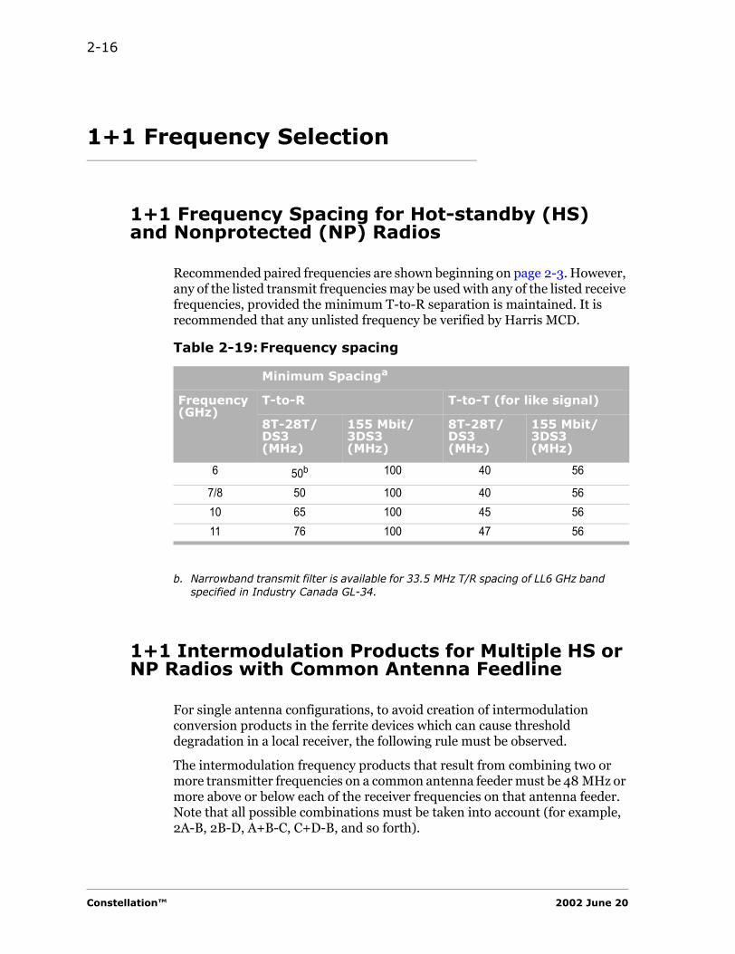
1+1 Frequency Selection
1+1 Frequency Spacing for Hot-standby (HS) and Nonprotected (NP) Radios
Recommended paired frequencies are shown beginning on page 2-3. However, any of the listed transmit frequencies may be used with any of the listed receive frequencies, provided the minimum T-to-R separation is maintained. It is recommended that any unlisted frequency be verified by Harris MCD.
1+1 Intermodulation Products for Multiple HS or NP Radios with Common Antenna Feedline
For single antenna configurations, to avoid creation of intermodulation conversion products in the ferrite devices which can cause threshold degradation in a local receiver, the following rule must be observed.
The intermodulation frequency products that result from combining two or more transmitter frequencies on a common antenna feeder must be 48 MHz or more above or below each of the receiver frequencies on that antenna feeder. Note that all possible combinations must be taken into account (for example, 2A-B, 2B-D, A+B-C, C+D-B, and so forth).
Table 2-19:Frequency spacing
Minimum Spacinga
a.
Frequency(GHz)
T-to-R T-to-T (for like signal)
8T-28T/ DS3(MHz)
155 Mbit/ 3DS3(MHz)
8T-28T/ DS3(MHz)
155 Mbit/ 3DS3(MHz)
6 50b
b. Narrowband transmit filter is available for 33.5 MHz T/R spacing of LL6 GHz band specified in Industry Canada GL-34.
100 40 56
7/8 50 100 40 5610 65 100 45 5611 76 100 47 56
Constellation™ 2002 June 20

Frequency Planning 2-17
FR
EQ
UEN
CY
P
LA
NN
ING
Regulatory Information Licensed Part 101 Service
* Maximum output power on FCC grant is listed here. Form 415 Item B8 should be the value from coordination and/or path data sheet.
Table 2-20:Regulatory information licensed Part 101 service
Emission Designator
Equipment ID Stability Max. Pwr.
Type of Service
Capacity T1/VC
Modulation Rate
Modulation Type
ATPC
(%) (watts) (Mbit/s) m
B4 B6 B7 B8* B9 B10 B11 B12 B14
Constellation (6 GHz, 8DS1)
3M75D7W HRS-CX-06G08D1 0.003 2.00 DIG 8 T1 13.8 32 QAM Y
Constellation (6 GHz, 16DS1)
5M0D7W HRS-CX-06G16D1 0.003 1.75 DIG 16 T1 27.1 128 QAM Y
Constellation (6 GHz, 28DS1)
10M0D7W HRS-CX-06G28D1 0.003 1.75 DIG 28 T1 47.0 64 QAM Y
Constellation (6 GHz, OC3/3DS3)
30M0D7W HRS-CX-06155M 0.003 1.75 DIG OC3/3DS3 169.66 128 TCM Y
Constellation (7/8 GHz, 8DS1)
3M75D7W HRS-CX-07G08D1 0.003 1.42 DIG 8 T1 13.8 32 QAM Y
Constellation (7/8 GHz, 16DS1)
5M0D7W HRS-CX-07G16D1 0.003 1.24 DIG 16 T1 27.1 128 QAM Y
Constellation (7/8 GHz, 28DS1)
10M0D7W HRS-CX-07G28D1 0.003 1.24 DIG 28 T1 47.0 64 QAM Y
Constellation (7/8 GHz, OC3/3DS3)
30M0D7W HRS-CX-07G155M 0.003 1.24 DIG OC3/3DS3 169.66 128 TCM Y
Constellation (10 GHz, 8DS1)
3M75D7W HRS-CX-10G08D1 0.003 0.71 DIG 8 T1 13.8 32 QAM Y
Constellation (10 GHz, 16DS1)
5M0D7W HRS-CX-10G16D1 0.003 0.62 DIG 16 T1 27.1 128 QAM Y
Constellation (11 GHz, 8DS1)
3M75D7W HRS-CX-11G08D1 0.003 0.71 DIG 8 T1 13.8 32 QAM Y
Constellation (11 GHz, 16DS1)
5M0D7W HRS-CX11G16D1 0.003 0.62 DIG 16 T1 27.1 128 QAM Y
Constellation (11 GHz, 28DS1)
10M0D7W HRS-CX-11G28D1 0.003 0.70 DIG 28 T1 47.0 64 QAM Y
Constellation (11 GHz, OC3/3DS3)
30M0D7W HRS-CX-11G155M 0.003 0.70 DIG OC3/3DS3 169.66 128 TCM Y
Harris Corporation Constellation™

2-18
Constellation™ 2002 June 20

CO
NS
TELLA
TIO
N
RA
DIO
C
ON
FIG
UR
ATIO
NS
C H A P T E R
3CONSTELLATION RADIO
CONFIGURATIONS
The Constellation Radio
The Constellation Radio is a scalable narrow, medium, and high capacity digital radio. The radios are available in 6, 7, 8, 10, and 11 GHz frequency bands.
The Constellation platform includes both terminal and repeater configurations. Repeater configuration radio supports an add/drop of up to 16 DS1 signals from each direction. The DS1 signals must be dropped in groups of four.
The high-capacity Constellation radio is not available in a repeater configuration, only in a back-to-back configuration.
Narrow/Medium Capacity Radio
• 4, 8, 16, 28* DS1 (terminal and repeater)• 1 DS3 (available in back-to-back, but not in repeater configuration)
* Supports a maximum of 16 DS1 add/drop signals from each direction. If more than 16 DS1 signals are to be dropped, then a back-to-back configuration is required.
Harris Corporation Constellation™

3-2
High Capacity Radio
• 3 DS3 with 1 DS1 wayside• 3 DS3 with add-drop capabilities• 2 DS3 + 28 DS1 with 1 DS1 wayside• OC-3 with 1 DS1 wayside• STM-1/STS-3 with 1 DS1 wayside
Upgradability
Requirements for upgrading from a medium to a high capacity radio are listed below. The current radios with -001, -002, or -003 Tx/Rx, which will be upgraded to OC-3 or 3xDS3.
• Swap the Modem and High Level Mux cards (and install splitter-combiner for 3xDS3 or cable interconnection bracket for STM1/STS3)
• Swap the transmit and receive waveguide filters (10 to 30 MHz bandwidth)
• Return/trade in Model 2 or existing Model 3 Transmitter and Receiver Assemblies to factory for upgrades
• Download new radio operating software• Cabling
3xDS3 and 155 Configurations
• The 3xDS3 unit is compatible with the HLM-155 unit. However, the 3xDS3 unit is not compatible with OEM SONET-DS3 multiplexers.
• The HLM-3xDS3 unit and the HLM-155 operate only in a terminal radio.
• At back-to-back terminals, when the receive DS3 signals are passed directly from radio to radio without passing through external terminating equipment, the maximum number of hops is limited to 15 because of the accumulation of jitter. After 15 hops, the DS3 must be terminated.
• When the 3x3DS3 system is configured in an add-drop mode, T1 signals may pass through no more that 5 consecutive add-drop sites before being terminated.
Constellation™ 2002 June 20

Constellation Radio Configurations 3-3
CO
NS
TELLA
TIO
N
RA
DIO
C
ON
FIG
UR
ATIO
NS
Network Management and Control
Network Management Interfaces
The Constellation Radio offers versatile open network management with an embedded SNMP agent and compatibility with Harris’ NetBoss, StarView, or FarScan network management platforms.
Craft Interface Tool
The Constellation also supports a Keypad interface. The Keypad can be used for local (per hop) and remote monitoring of alarms and statuses for any radio in a contiguous network, and for provisioning the network elements. The Keypad allows the customer to quickly configure a system or diagnose a trouble on a hop.
In place of a Keypad, the customer can connect a terminal (VT100-compatible) or a laptop with terminal emulator software to communicate with the Constellation radio.
External Alarm/Control
Eight alarm dry-contact relay outputs (Keypad programmable) and eight opto-isolated alarm inputs are provided for customer-configured alarms.
Antenna Coupling Unit (ACU)
The ACU options offer a wide variety of optimal RF transmission architectures as well as expansion ports that accommodate additional radios on existing antenna feed systems. Refer to Chapter 6 for more information.
Harris Corporation Constellation™

3-4
Multiplexer Configurations
Figure 3-1: Multiplexer configuration for a radio terminal
Figure 3-2: Multiplexer configuration for a radio-to-radio repeater
RADIOA
MODEMA
MUX
JF
1-28 DS1s (in group of 4 DS1s)
SERVICECHANNEL
RADIOA
MODEMA
MUX
JF
0-16 DS1s(in group of 4 DS1s
RADIOB
MODEMB
JF
0-16 DS1s
8 to 28 DS1s
SERVICECHANNEL
(EXPANSION SHELF)
(in group of 4 DS1sto any M12 slot 1-4) to any M12 slot 5-8)
Constellation™ 2002 June 20

Constellation Radio Configurations 3-5
CO
NS
TELLA
TIO
N
RA
DIO
C
ON
FIG
UR
ATIO
NS
Figure 3-3: Multiplexer configuration for a dual radio terminal
Constellation DS3 Interface Configurations
Figure 3-4: Constellation radio terminal, DS3 interface
RADIOA
MODEMA
MUX
JF
RADIOA
MODEMA
JF
1-28 DS1s
MUX
SERVICECHANNEL
SERVICECHANNEL
(in group of 4 DS1s)(in group of 4 DS1s)1-28 DS1s
RADIOA
MODEMA
DS3 INTERFACE
JF
DS3
(a) Radio Terminal
RADIOA
MODEMA
DS3
JF
DS3
(b) Dual Radio Terminal
RADIOA
MODEMA
JF
DS3
INTFDS3INTF
SERVICECHANNEL
SERVICECHANNEL
SERVICECHANNEL
Harris Corporation Constellation™

3-6
Figure 3-5: 28 DS1 to DS3 application
RADIOA
MODEMA
DS3 HLM
JF
DS3
SERVICECHANNEL
RADIOA
MODEMA
JF
1-28 DS1s
HLM
SERVICECHANNEL
(in group of 4 DS1s)
28 DS1
3/1DCS
DS3
DS1
DS3(CPE)
Constellation™ 2002 June 20

Constellation Radio Configurations 3-7
CO
NS
TELLA
TIO
N
RA
DIO
C
ON
FIG
UR
ATIO
NS
Figure 3-6: 28 DS1 to repeater to DS3 application
RA
DIO
A
MO
DEM
A
DS3
HLM
JF
DS3
SERV
ICE
CH
AN
NEL
RA
DIO
A
MO
DEM
A
JF
28 D
S1s
HLM
SERV
ICE
CH
AN
NEL 28
DS1
3/1
DC
SD
S3
DS1
DS3
(CPE
)
RA
DIO
A
MO
DEM
A
HLM
28
DS1
JF
0-16
DS1
s(in
gro
up o
f 4 D
S1s
RA
DIO
B
MO
DEM
B
JF
0-16
DS1
s
8 to
28
DS1
s
SERV
ICE
CH
AN
NEL
(EX
PAN
SIO
N S
HEL
F)
(in g
roup
of 4
DS1
sto
any
M12
slot
1-4
)to
any
M12
slot
5-8
)
RPT
R
Harris Corporation Constellation™

3-8
Constellation 3xDS3 Interface Configurations
Figure 3-7: 3xDS3 to 3xDS3 configuration
Figure 3-8: 3xDS3 to 3xDS3 back-to-back terminals (repeater)
RADIOA
MODEMA
DS3 HLM
JF
DS3-1
SERVICECHANNEL
JF
DS3-2
JF
DS3-3
RADIOA
MODEMA
DS3 HLM
JF
DS3-3
SERVICECHANNEL
JF
DS3-2
JF
DS3-1
RADIOA
MODEMA
DS3 HLM
JF
DS3-1
SERVICECHANNEL
JF
DS3-2
JF
DS3-3
RADIOA
MODEMA
DS3 HLM
JF
DS3-3
SERVICECHANNEL
JF
DS3-2
JF
DS3-1
Constellation™ 2002 June 20

Constellation Radio Configurations 3-9
CO
NS
TELLA
TIO
N
RA
DIO
C
ON
FIG
UR
ATIO
NS
Figure 3-9: 2xDS3 + 28DS1 configuration
Figure 3-10: 2xDS3 + 28DS1 back-to-back terminals (repeater)
RADIOA
MODEMA
DS3 HLM
JF
SERVICECHANNEL
JF
DS3
JF
DS3
RADIOA
MODEMA
DS3 HLM
JF
DS3
SERVICECHANNEL
JF
DS3
JF
4-28 DS1s 4-28 DS1s
RADIOA
MODEMA
DS3 HLM
JF
4-28 DS1s
SERVICECHANNEL
JF
DS3
JF
DS3
RADIOA
MODEMA
DS3 HLM
JF
DS3
SERVICECHANNEL
JF
DS3
JF
4-28 DS1s
Harris Corporation Constellation™

3-10
Radio Synchronization Configuration
The High Level Mux (HLM) cards in a repeater configuration can be set for either Through timing or Source timing.
Through timing mode minimizes the jitter accumulation on DS1s directly passing through multiple repeaters.
In a loop system with all repeaters, at least one repeater needs to be set for Source timing. In large systems, the HLM cards in repeater configurations need to be set for Source timing after 15 consecutive repeaters to clear the accumulated jitter.
The HLM cards in a terminal configuration are always set for Source timing.
If Source timing is selected, the Service Channel must be configured with Local Off Hook enabled.
Constellation™ 2002 June 20
TEC
HN
ICS
PEC
IFIC
AT
C H A P T E R
4TECHNICAL SPECIFICATIONS
Power Requirements (Top of Rack)
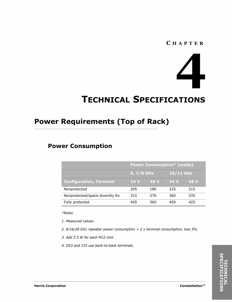
Power Consumption
*Notes
1. Measured values.
2. 8/16/28 DS1 repeater power consumption = 2 x terminal consumption, less 5%.
3. Add 3.5 W for each M12 Unit.
4. DS3 and 155 use back-to-back terminals.
Power Consumption* (watts)
6, 7/8 GHz 10/11 GHz
Configuration, Terminal 24 V 48 V 24 V 48 V
Nonprotected 205 180 225 215
Nonprotected/space diversity Rx 315 270 360 335
Fully protected 405 360 450 425
Harris Corporation Constellation™
AL
ION
S

4-2
Power Source
Power Source Voltage
Power Source Noise
The battery noise level must comply with Figure 4-1.
Figure 4-1: Battery voltage noise limit
Built-in Radio Fuse Panel
Constellation radio has a built-in radio fuse panel whose power rating is designed to provide individual fused power only to the various assemblies in the radio equipment shelf. Harris recommends that external fuse panel be used to provide fused power to all other equipment on the same radio rack.
System DC power input Wide mouth auto polarity directing 22 Vdc to 60 Vdc at top of rack (TOR)
Input noise level and ripple tolerated
100 mV RMS in a 3-kHz bandwidth, 100 kHz to 20 MHz
Protection Fused
1
2
3
4
5
6
10 100 1k 10k 100kNOISE FREQUENCY (Hz)
(V RMS)NOISE LEVEL
E2
E1
Where
Constellation™ 2002 June 20

Technical Specifications 4-3
TEC
HN
ICS
PEC
IFIC
AT
Circuit Breakers
The values in Table 4-1 are for the Constellation radio only.
RF Performance Specifications
Table 4-2 shows values measured at the Top of Rack Antenna Port, guaranteed at 25°C for nonprotected systems.
See the table below for additional ACU (Antenna Coupling Unit) loss:
Table 4-1: Recommended circuit breaker sizes
6, 7/8 GHz 10/11 GHz
Configuration 24 V 48 V 24 V 48 V
Fully protected 25 A 15 A 30 A 15 A
Table 4-2: Additional ACU loss
Band (GHz) Configuration Additional ACU Loss (dB)
6, 7/8, and 11 Protected transmit pair 0.4
6 and 11 Protected receive pair 1.0
7/8 8/16/28 DS1 0.9
7/8 155 Mbit/s 0.8
Harris Corporation Constellation™
AL
ION
S

4-4
Table 4-3: RF performance specifications
Receive Threshold
System Gaina
Band (GHz) Capacity Config-urationb
Tx Pwr Output (dBm)
10-3 BER(dBm)
10-6 BER(dBm)
10-3 BER(dB)
10-6 BER(dB)
5.9 to 6.9 c 8 DS1 NP 29.5 -82.5 -81.0 112.0 110.5NP/SD 29.5 -82.5 -81.0 112.0 110.5HSd 29.1 -81.3 -79.8 110.4 108.9HS/SD 29.1 -82.5 -81.0 111.6 110.1ST/SD 29.1 -82.5 -81.0 111.6 110.1FD 29.5 -82.5 -81.0 112.0 110.5FD/SD 29.5 -82.5 -81.0 112.0 110.5
16 DS1 NP 28.5 -76.0 -74.5 104.5 103.0NP/SD 28.5 -76.0 -74.5 104.5 103.0HSd 28.1 -75.0 -73.5 103.1 101.6HS/SD 28.1 -76.0 -74.5 104.1 102.6ST/SD 28.1 -76.0 -74.5 104.1 102.6FD 28.5 -76.0 -74.5 104.5 103.0FD/SD 28.5 -76.0 -74.5 104.5 103.0
28 DS1/DS3 NP 29.0 -76.0 -74.5 105.0 103.5NP/SD 29.0 -76.0 -74.5 105.0 103.5HSd 28.6 -74.8 -73.3 103.4 101.9HS/SD 28.6 -76.0 -74.5 104.6 103.1ST/SD 28.6 -76.0 -74.5 104.6 103.1FD 29.0 -76.0 -74.5 105.0 103.5FD/SD 29.0 -76.0 -74.5 105.0 103.5
155 Mbit/s NP 29.0 -72.5 -71.0 101.5 100.0NP/SD 29.0 -72.5 -71.0 101.5 100.0HSd 28.6 -71.5 -70.0 100.1 98.6HS/SD 28.6 -72.5 -71.0 101.1 99.6ST/SD 28.6 -72.5 -71.0 101.1 99.6FD 29.0 -72.5 -71.0 101.5 100.0FD/SD 29.0 -72.5 -71.0 101.5 100.0
Constellation™ 2002 June 20

Technical Specifications 4-5
TEC
HN
ICS
PEC
IFIC
AT
7 to 8 8 DS1 NP 27.5 -81.5 -80.0 109.0 107.5NP/SD 27.5 -81.5 -80.0 109.0 107.5HSd 27.1 -80.6 -79.1 107.7 106.2HS/SD 27.1 -81.5 -80.0 108.6 107.1ST/SD 27.1 -81.5 -80.0 108.6 107.1FD 27.5 -81.5 -80.0 109.0 107.5FD/SD 27.5 -81.5 -80.0 109.0 107.5
16 DS1 NP 26.5 -75.0 -73.5 101.5 100.0NP/SD 26.5 -75.0 -73.5 101.5 100.0HSd 26.1 -74.1 -72.6 100.2 98.7HS/SD 26.1 -75.0 -73.5 101.1 99.6ST/SD 26.1 -75.0 -73.5 101.1 99.6FD 26.5 -75.0 -73.5 101.5 100.0FD/SD 26.5 -75.0 -73.5 101.5 100.0
28 DS1/DS3 NP 27.0 -75.0 -73.5 102.0 100.5NP/SD 27.0 -75.0 -73.5 102.0 100.5HSd 26.6 -74.1 -72.6 100.7 99.2HS/SD 26.6 -75.0 -73.5 101.6 100.1ST/SD 26.6 -75.0 -73.5 101.6 100.1FD 27.0 -75.0 -73.5 102.0 100.5FD/SD 27.0 -75.0 -73.5 102.0 100.5
155 Mbit/s NP 27.5 -72.0 -70.5 99.5 98.0NP/SD 27.5 -72.0 -70.5 99.5 98.0HSd 27.1 -71.2 -69.7 98.3 96.8HS/SD 27.1 -72.0 -70.5 99.1 97.6ST/SD 27.1 -72.0 -70.5 99.1 97.6FD 27.5 -72.0 -70.5 99.5 98.0FD/SD 27.5 -72.0 -70.5 99.5 98.0
Table 4-3: RF performance specifications (Continued)
Receive Threshold
System Gaina
Band (GHz) Capacity Config-urationb
Tx Pwr Output (dBm)
10-3 BER(dBm)
10-6 BER(dBm)
10-3 BER(dB)
10-6 BER(dB)
Harris Corporation Constellation™
AL
ION
S
4-6
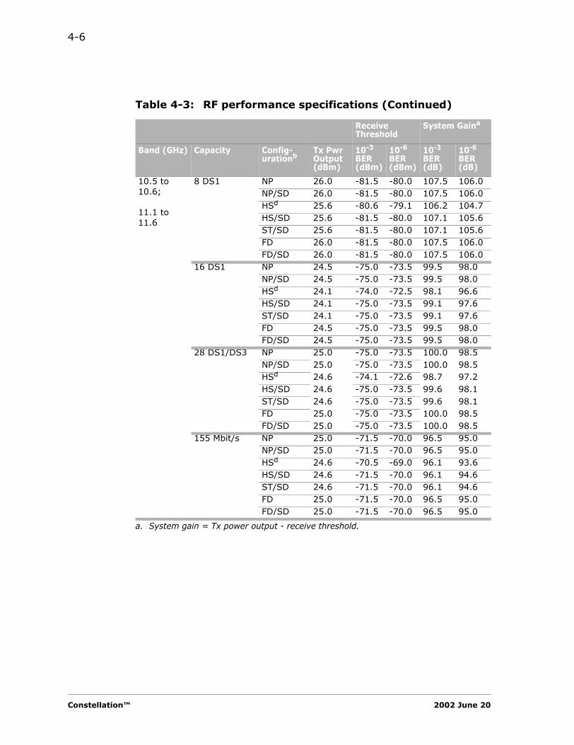
10.5 to 10.6;
11.1 to 11.6
8 DS1 NP 26.0 -81.5 -80.0 107.5 106.0NP/SD 26.0 -81.5 -80.0 107.5 106.0HSd 25.6 -80.6 -79.1 106.2 104.7HS/SD 25.6 -81.5 -80.0 107.1 105.6ST/SD 25.6 -81.5 -80.0 107.1 105.6FD 26.0 -81.5 -80.0 107.5 106.0FD/SD 26.0 -81.5 -80.0 107.5 106.0
16 DS1 NP 24.5 -75.0 -73.5 99.5 98.0NP/SD 24.5 -75.0 -73.5 99.5 98.0HSd 24.1 -74.0 -72.5 98.1 96.6HS/SD 24.1 -75.0 -73.5 99.1 97.6ST/SD 24.1 -75.0 -73.5 99.1 97.6FD 24.5 -75.0 -73.5 99.5 98.0FD/SD 24.5 -75.0 -73.5 99.5 98.0
28 DS1/DS3 NP 25.0 -75.0 -73.5 100.0 98.5NP/SD 25.0 -75.0 -73.5 100.0 98.5HSd 24.6 -74.1 -72.6 98.7 97.2HS/SD 24.6 -75.0 -73.5 99.6 98.1ST/SD 24.6 -75.0 -73.5 99.6 98.1FD 25.0 -75.0 -73.5 100.0 98.5FD/SD 25.0 -75.0 -73.5 100.0 98.5
155 Mbit/s NP 25.0 -71.5 -70.0 96.5 95.0NP/SD 25.0 -71.5 -70.0 96.5 95.0HSd 24.6 -70.5 -69.0 96.1 93.6HS/SD 24.6 -71.5 -70.0 96.1 94.6ST/SD 24.6 -71.5 -70.0 96.1 94.6FD 25.0 -71.5 -70.0 96.5 95.0FD/SD 25.0 -71.5 -70.0 96.5 95.0
a. System gain = Tx power output - receive threshold.
Table 4-3: RF performance specifications (Continued)
Receive Threshold
System Gaina
Band (GHz) Capacity Config-urationb
Tx Pwr Output (dBm)
10-3 BER(dBm)
10-6 BER(dBm)
10-3 BER(dB)
10-6 BER(dB)
Constellation™ 2002 June 20

Technical Specifications 4-7
TEC
HN
ICS
PEC
IFIC
AT
Transmitter
Frequency Stability
+/-0.0003% = +/-3 ppm
Unwanted (Out-of-Band and Spurious) Emissions
The Constellation radio meets the following specifications:• FCC Part 101 Section 101.111, Emission Limitations.• FCC Part 15, Subpart B, Class A
b. Configurations:
NP = nonprotected transmitter and receiver
NP/SD = nonprotected transmitter, space diversity receivers
HS = hot standby transmitters, protected receivers
HS/SD = hot standby transmitters, space diversity receivers
ST/SD = split transmitters/space diversity receivers; separate main (transmit and receive) and space diversity (transmit and receive) antennas.
FD = Frequency diversity transmitters and receivers.
FD/SD = Frequency diversity transmitters, space diversity receivers or hybrid diversity receivers.
c. System gain is 1 dB lower for LL6 GHz band (5850-5915 MHz).
d. For HS, thresholds are for RCVR 1 (main); thresholds for RCVR 2 (standby) are approximately 6 dB higher.
Harris Corporation Constellation™
AL
ION
S

4-8
Receiver
General Specifications
Refer to Chapter 11 for performance curves.
Receiver Overload*
* Typical values for nonprotected systems measured at the antenna port of the Antenna Coupling Unit (ACU).
Frequency stability ± 0.0003% = ± 3 ppm
Residual BER (typical at room temperature) < 10-12 per hop or link
Receiver image rejection > 90 dB
Band (GHz) 10-6 BER (dBm) 10-3 BER (dBm)
6 -17.0 -16.0
7/8 -17.5 -16.5
10/11 -18.5 -17.5
Constellation™ 2002 June 20
Technical Specifications 4-9
TEC
HN
ICS
PEC
IFIC
AT
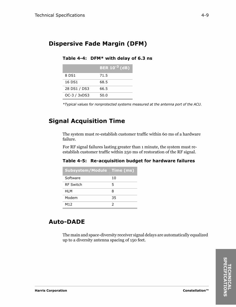
Dispersive Fade Margin (DFM)
*Typical values for nonprotected systems measured at the antenna port of the ACU.
Signal Acquisition Time
The system must re-establish customer traffic within 60 ms of a hardware failure.
For RF signal failures lasting greater than 1 minute, the system must re-establish customer traffic within 250 ms of restoration of the RF signal.
Auto-DADE
The main and space-diversity receiver signal delays are automatically equalized up to a diversity antenna spacing of 150 feet.
Table 4-4: DFM* with delay of 6.3 ns
BER 10-3 (dB)
8 DS1 71.5
16 DS1 68.5
28 DS1 / DS3 66.5
OC-3 / 3xDS3 50.0
Table 4-5: Re-acquisition budget for hardware failures
Subsystem/Module Time (ms)
Software 10
RF Switch 5
HLM 8
Modem 35
M12 2
Harris Corporation Constellation™
AL
ION
S

4-10
Tributary Interface
Tributary Signal Characteristics
Tributary Jitter
• Jitter transfer conforms to AT&T Standard TR-62411.• Jitter tolerance conforms to Bellcore Standard GR-499, Section 7.3.2.• Jitter generation conforms to Bellcore Standard GR-499, Section 7.3.3.• The DS1 interface meets the jitter transfer and jitter acceptance
requirements of ITU-T G.958 and Bellcore GR-253.• Jitter curves are given in Chapter 11, “Performance Curves”.
Tributary Specification Compliance
Tributary Bit Rate(Mbit/s)
Impedance/Connector
Line Code
Length
DS1 1.544 100 ohms/50-pin AMI/B8ZS 655 feet to DSX-1
E1 2.048 120 ohms/50-pin HDB3 6 dB at 1.024 MHz
DS3 44.736 75 ohms/BNC female B3ZS 450 feet to DSX-3
E1 (wayside) 2.048 75 ohms/BNC femaleor120 ohms/RJ-45
HDB3 6 dB at 1.024 MHz
DS1 (wayside) 1.544 100 ohms/RJ-45 AMI/B8ZS 655 feet to DSX-1
Tributary Bit Rate(Mbit/s)
Bellcore ANSI ITU-T
DS1 1.544 GR-499-CORE, Section 9.3 T1.102-1993 G.703
DS3 44.736 GR-499-CORE T1.102-1993 G.703
E1 2.048 G.703
Constellation™ 2002 June 20
Technical Specifications 4-11
TEC
HN
ICS
PEC
IFIC
AT
Signal Processing
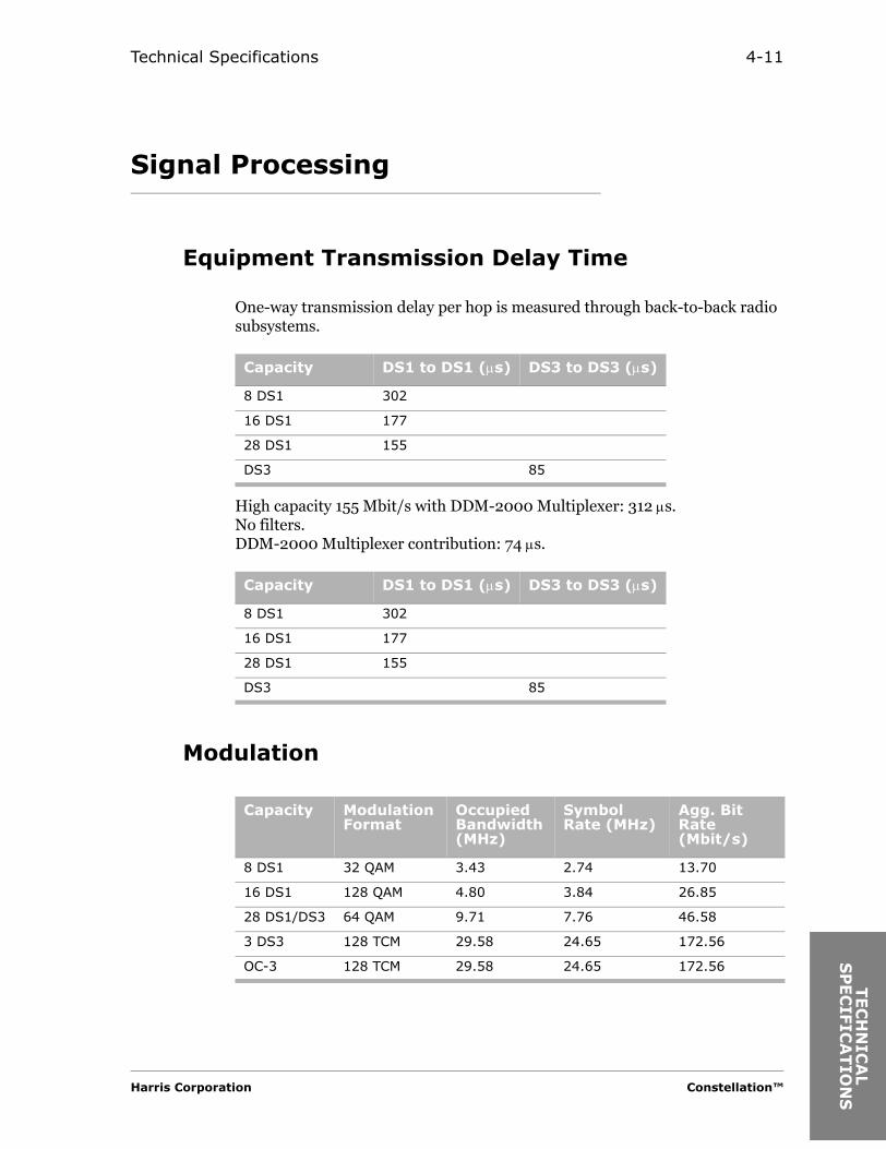
Equipment Transmission Delay Time
One-way transmission delay per hop is measured through back-to-back radio subsystems.
High capacity 155 Mbit/s with DDM-2000 Multiplexer: 312 µs.No filters.DDM-2000 Multiplexer contribution: 74 µs.
Modulation
Capacity DS1 to DS1 (µs) DS3 to DS3 (µs)
8 DS1 302
16 DS1 177
28 DS1 155
DS3 85
Capacity DS1 to DS1 (µs) DS3 to DS3 (µs)
8 DS1 302
16 DS1 177
28 DS1 155
DS3 85
Capacity Modulation Format
Occupied Bandwidth (MHz)
Symbol Rate (MHz)
Agg. Bit Rate (Mbit/s)
8 DS1 32 QAM 3.43 2.74 13.70
16 DS1 128 QAM 4.80 3.84 26.85
28 DS1/DS3 64 QAM 9.71 7.76 46.58
3 DS3 128 TCM 29.58 24.65 172.56
OC-3 128 TCM 29.58 24.65 172.56
Harris Corporation Constellation™
AL
ION
S

4-12
Forward Error Correction (FEC)
Reed-Solomon 8-byte error correcting code is implemented in the Constellation Modem. The overall FEC code rate is 204/188.
For the High Capacity 155 Modem, the modulation format is 128 TCM with an FEC code rate of 238/232.
Intermediate Frequency Signal
Transmit and receive 140 MHz IF frequency signals are maintained at a level of -8 dBm. The impedance is 50 ohms and the return loss is 15 dB at the IF interfaces.
Protection Switching
1+1 Transmitter and Receiver Switching
Hot-Standby Transmitter Switching
Hot-standby (HS) Transmitter protection switching is automatically caused by a Transmitter fault or by reverse path protection and is nonrevertive.
Reverse Path Protection
Reverse path protection software enables a HS radio to automatically switch from the on-line Transmitter to the standby Transmitter when the Receiver has a sync loss alarm. Reverse path protection is accomplished in less than 60 milliseconds.
Modulation Format
C/N with FECBER 10-6 (dB)
32 QAM 22
64 QAM 25
128 QAM 28
128 TCM 24
Constellation™ 2002 June 20

Technical Specifications 4-13
TEC
HN
ICS
PEC
IFIC
AT
HS Receiver Switching
Hot-standby Receiver protection switching is automatically caused by a Receiver fault and does not revert to the main Receiver after the fault clears. Path and maintenance switching do not introduce errors. Switching caused by a fault introduces errors.
Space Diversity Receiver Switching
Space diversity protected Receiver switching is automatic and nonrevertive. Space diversity receive switching is errorless and employs an anticipatory function which uses performance degradation as an indicator.
Receiver Switching Criteria
Receiver switching is based on receive uncorrected BER (UBER) alarm and received signal level (RSL) alarm.
Uncorrected BER (UBER) Alarm
This received signal degradation indication is based on an error syndrome count. When the Receiver under stress begins to make errors which are corrected by the FEC decoder, error syndromes are generated.
Received Signal Level (RSL) Alarm
The RSL alarm is based on a predetermined RSL threshold level.
Maintenance
Protected Transmitters and Receivers are arranged to allow repair of a single Transmitter or a Receiver without removing the traffic.
Manual Switch-over
A control capability is provided to switch the main and standby Transmitters or Receivers to lock-on main or lock-on standby. Manual locking of a protected Transmitter or Receiver is reported as a minor alarm. Manual Receiver switching has no effect on traffic.
Harris Corporation Constellation™
AL
ION
S

4-14
1+1 Switching Times
The average recovery time for switching caused by hardware failures in a protected system is 60 ms or less.
For temporary signal interruptions of 1 to 2 seconds duration, no more than 5% of recovery times will exceed 0.5 second.
Supervisory Interfaces
Network Management Interface
* Inverted mark/space polarity.
Note: Refer to the Constellation Installation and Maintenance manual for pinout information and data rates.
Table 4-6: Network management interface
Port Signal Application
FSCAN RS-232 async FarScan computer connection
Monitor RS-232 async SCAN interconnection
VersaT1lity RS-232 async or RS-423* async
SCAN interconnection
Keypad RS232 async Hand-held Keypad connection
Aux RS-422 sync Constellation Radio interconnection
Spur RS-422 sync Constellation Radio interconnection
Ethernet 10Base-T SNMP
Constellation™ 2002 June 20

Technical Specifications 4-15
TEC
HN
ICS
PEC
IFIC
AT
Alarms
Alarm Indication Signal (AIS)
The AIS signal is transmitted under the following conditions on a line input by line input basis:
• When an AIS signal is received at the line input.• When equipment failure causes a loss of signal to the multiplexer.
The AIS signal is removed once line data has been restored to the M12 Unit.
Radio Alarm LED Indicators
Radio alarm LED indicators are:• MAJOR (red)• MINOR (red)• STATUS (yellow)
Site Status Inputs and Control Outputs
Eight relay outputs and eight opto-isolated alarm inputs are provided on External Alarm/Control connector. Input level of alarm input shall be open or ground.
The first two relay outputs are pre-defined to LOCAL MAJOR and LOCAL MINOR alarms in the factory. The other six relay outputs can be used for customer site command outputs or radio alarm outputs.
Harris Corporation Constellation™
AL
ION
S
4-16
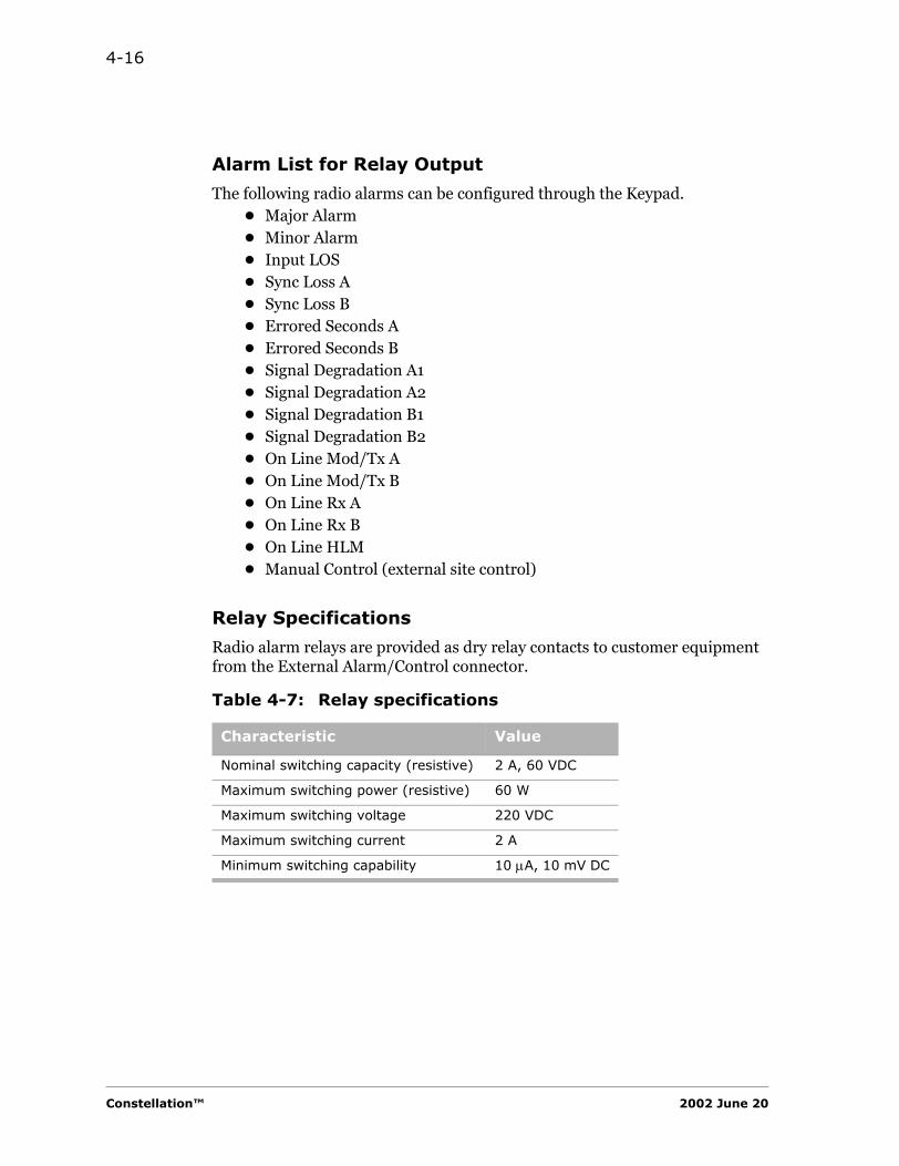
Alarm List for Relay Output
The following radio alarms can be configured through the Keypad.• Major Alarm• Minor Alarm• Input LOS• Sync Loss A• Sync Loss B• Errored Seconds A• Errored Seconds B• Signal Degradation A1• Signal Degradation A2• Signal Degradation B1• Signal Degradation B2• On Line Mod/Tx A• On Line Mod/Tx B• On Line Rx A• On Line Rx B• On Line HLM• Manual Control (external site control)
Relay Specifications
Radio alarm relays are provided as dry relay contacts to customer equipment from the External Alarm/Control connector.
Table 4-7: Relay specifications
Characteristic Value
Nominal switching capacity (resistive) 2 A, 60 VDC
Maximum switching power (resistive) 60 W
Maximum switching voltage 220 VDC
Maximum switching current 2 A
Minimum switching capability 10 µA, 10 mV DC
Constellation™ 2002 June 20
Technical Specifications 4-17
TEC
HN
ICS
PEC
IFIC
AT
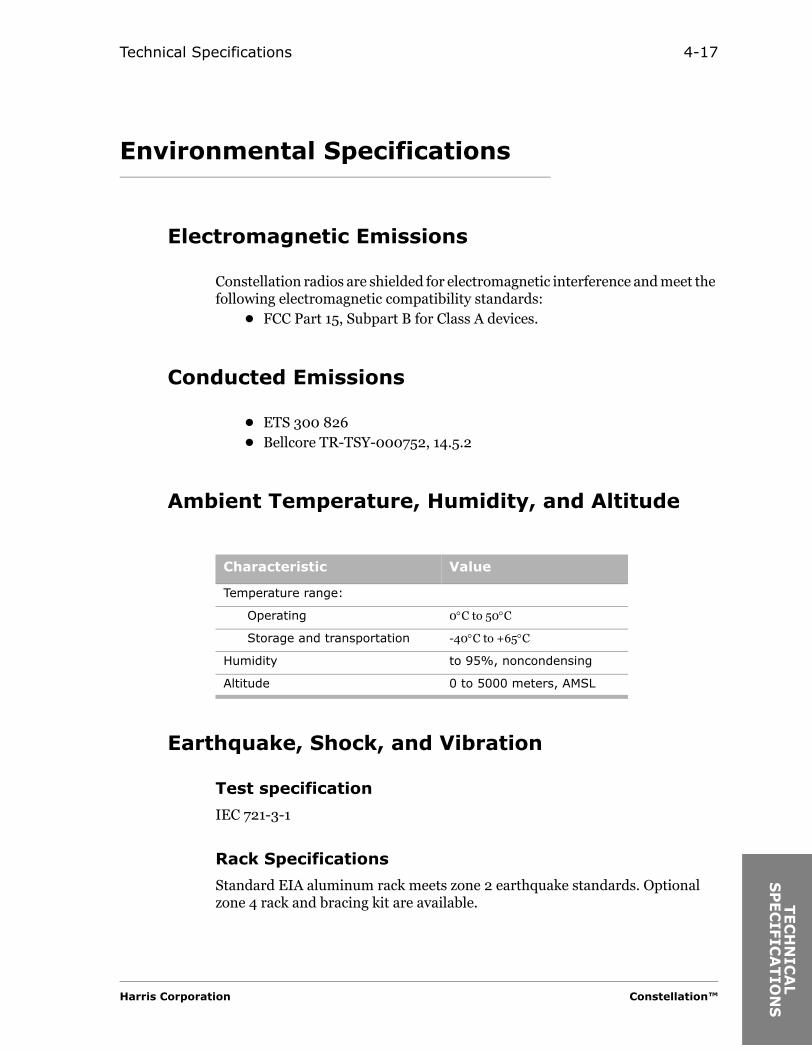
Environmental Specifications
Electromagnetic Emissions
Constellation radios are shielded for electromagnetic interference and meet the following electromagnetic compatibility standards:
• FCC Part 15, Subpart B for Class A devices.
Conducted Emissions
• ETS 300 826• Bellcore TR-TSY-000752, 14.5.2
Ambient Temperature, Humidity, and Altitude
Earthquake, Shock, and Vibration
Test specification
IEC 721-3-1
Rack Specifications
Standard EIA aluminum rack meets zone 2 earthquake standards. Optional zone 4 rack and bracing kit are available.
Characteristic Value
Temperature range:
Operating 0°C to 50°C
Storage and transportation -40°C to +65°C
Humidity to 95%, noncondensing
Altitude 0 to 5000 meters, AMSL
Harris Corporation Constellation™
AL
ION
S

4-18
Mechanical Dimensions
EIA Rack
Refer to Appendix A for information on a Harris standard rack.
Constellation Radio
* Radio mounts in a standard 19-inch wide rack. Dimensions include branching circulators, fully configured ACU and doors. Cannot be flush-mounted.
** With ADM. 1-3xDS3 and OC3 use back-to-back terminals.
Weights (Typical)
Configuration* Unit Height Depth Width
Terminal Millimeters 622 300 445
Inches 24.5 11.8 17.5
8/16/28xDS1 Repeater**
Millimeters 1200 300 445
Inches 47.25 11.8 17.5
Configuration pound kg
Constellation terminal (fully equipped)(MHSB, 28 x DS1 terminal)
74 33.6
Constellation repeater (fully equipped) 127 57.6
7-foot x 19-inch rack 35 15.9
Constellation™ 2002 June 20

SY
STEM
IN
TER
CO
NN
EC
T
AN
D
C H A P T E R
5SYSTEM INTERCONNECT AND
CONFIGURATION
System Interconnection
Orderwire Interconnection
Table 5-1 describes the interconnection between the Harris MCD Service Channel equipment and the Constellation radio.
Harris Corporation Constellation™

5-2
Table 5-1: Orderwire interconnection
Constellation Port
ConnectorType
Radio Equipment
Port Connector Type
Signal
VF PORT 1 RJ45 DVS II VF1 50-pin female
4W VF (600 Ω)
VF2 50-pin female
MegaStar VF1B DB-25 female
VF2A DB-25 female
VF2B
MicroStar L 4W VF RJ-45
MicroStar L (16 E1)
DE-9 female
MicroStar M (1 rms IDU)
DC-37 female
MicroStar M/H(3 rms IDU)
DE-9 female
VF PORT 2 RJ45 DVSII VF1 50-pin female
4W VF (600 Ω)
VF1 AUX
VF2 50-pin female
VF2 AUX
MegaStar VF1A DB-25 female
VF1B
VF2A DB-25 female
MicroStar L 4W VF RJ-45
MicroStar L (16 E1)
DE-9 female
MicroStar M(1 rms IDU)
DC-37 female
MicroStar M/H(3 rms IDU)
DE-9 female
Constellation™ 2002 June 20
System Interconnect and Configuration 5-3
SY
STEM
IN
TER
CO
NN
EC
T
AN
D
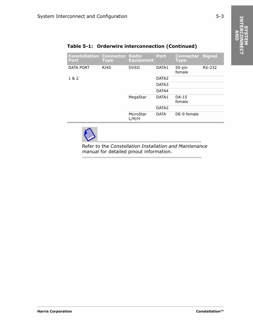
Refer to the Constellation Installation and Maintenance manual for detailed pinout information.
DATA PORT RJ45 DVSII DATA1 50-pin female
RS-232
1 & 2 DATA2
DATA3
DATA4
MegaStar DATA1 DA-15 female
DATA2
MicroStar L/M/H
DATA DE-9 female
Table 5-1: Orderwire interconnection (Continued)
Constellation Port
ConnectorType
Radio Equipment
Port Connector Type
Signal
Harris Corporation Constellation™

5-4
Four-Wire VF Orderwire Interface
Connector: RJ45
One VF orderwire channel provides two 4-wire VF ports.
Table 5-2: Four-wire VF Orderwire input specifications
VF Port Input Levelsa
a. Selectable through the Keypad.
Output Levelsa
VF1 0 dBm (default)-16 dBm
0 dBm (default)+7 dBm
VF2 0 dBm (default)+7 dBm
0 dBm (default)-16 dBm
Table 5-3: Four-wire VF ports performance specificationsa
a. Specifications are for one drop/insert.
Frequency response 300-3400 Hz, ±1.5 dB
Idle noise C-message ≤ 30 dBrnc0
Quantizing noise ≤ 56 dBrnc0 at 1004 Hz
Return loss ≥ 40 dB (telephone set on-hook)≥ 15 dB (telephone set off-hook when only one telephone is connected to 2-wire port)
Impedance 600 ohms, balanced
Output level accuracy ±1.0 dB
Table 5-4: Ringing generator specifications
Load 2 REN
Voltage (rated load) 60 Vrms
Ringing cadence ON 2.3 sec
Ringing cadence OFF 4.7 sec
Constellation™ 2002 June 20

System Interconnect and Configuration 5-5
SY
STEM
IN
TER
CO
NN
EC
T
AN
D
Two-Wire VF Orderwire Interface
Standard 2-wire telephone jack (RJ11).
Address
The DTMF receiver decoder can be set (using the Keypad) to any address between 000 and 999. This feature is compatible with DVS II orderwire and Megastar orderwire. The * key causes all stations to be called. The # key is not used by the Constellation VF Orderwire but is used by the DVS II orderwire to cancel the “all call” at the DVS II sites.
Data Orderwire Interface
Connector: RJ45
Maximum Distance: 50 feet (worst case)
One data channel provides two RS-232 ports.
Two RS-232 data ports can be selected to be bridged together providing half-duplex communications or selected to be isolated providing full duplex in a port-to-port application. Data can be set for sampling or asynchronous start-stop data signals. When data is set for sampling, data rates up to 4800 bit/s can be used with no restriction on the size of the data byte. When asynchronous start-stop is selected, bit rates 9600 bit/s or 19.2 kbit/s are available with the data byte set to 8 bits. A parity option can be enabled to send the parity bit through the system. The system does not monitor the parity bit.
Harris Corporation Constellation™

5-6
Table 5-5: Output voltage range (with 7k ohm load)
Minimum (V) Maximum (V)
Low – 5 –11
High + 5 +11
Table 5-6: Input voltage range
Minimum(V)
Maximum(V)
Low 0 + 0.8
High + 3.6 +5.0
Constellation™ 2002 June 20

System Interconnect and Configuration 5-7
SY
STEM
IN
TER
CO
NN
EC
T
AN
D
SCAN Equipment Interconnection
Table 5-7 describes the interconnection between Harris MCD SCAN (system control and alarm network) equipment and the Constellation radio.
Table 5-7: SCAN equipment interconnection
Constellation Port
Connector Type
Radio Equipment
Port Connector Type
Signal
AUX RJ45 Constellation AUX RJ45 RS-422
SPUR SPUR
VERSAT1LITY RJ45 CAU COMM 1 DE-9 female RS-232 or RS-423*
COMM 2
COMM 3
RTU
DVA COMM 1 DE-9 female RS-232 or RS-423*
COMM 2 RS-232 or RS-423*
COMM 3 RS-423*
COMM 4 RS-423*
COMM 5 RS-423*
DVM/DVL/ INT CTL DB-25 female RS-423*
DVT EXT B
GlobeStar RTU DE-9 female RS-232 or RS-423*
MegaStar AUX DE-9 female RS-232 or RS-423*
SPUR
MicroStar L/M/H
RTU DE-9 female RS-232 or RS-423*
Harris Corporation Constellation™

5-8
* RS-423 is with inverted Mark/Space polarity.
Refer to the Constellation Installation and Maintenance Manual for detailed pinout information.
Monitor RJ45 CAU COMM 1 DE-9 female RS-232
COMM 2
COMM 3
RTU
DVA COMM 1 DE-9 female RS-232
COMM 2
GlobeStar RTU DE-9 female RS-232
MegaStar AUX DE-9 female RS-232
SPUR
MicroStar L/M/H
RTU DE-9 female RS-232
FSCAN RJ45 FarScan PC COMM DE-9 male RS-232
HNM UNIX Station
COMM DB-25 female RS-232
ETHERNET RJ45 StarView PC LAN RJ45 10Base-T
Table 5-7: SCAN equipment interconnection (Continued)
Constellation Port
Connector Type
Radio Equipment
Port Connector Type
Signal
Constellation™ 2002 June 20

AN
TEN
NA
C
OU
PLIN
G U
NIT
(A
CU
)
C H A P T E R
6ANTENNA COUPLING UNIT
(ACU)
ACU Waveguide Flanges
Table 6-1: Standard flange specifications
Band (GHz) Flange Type Tapped
5.9 to 7.125 CMR-137 #6-32
7.1 to 8.5 CMR-112 #6-32
10.5 to 11.7 UG-39 #8-32
Table 6-2: Spacer adapter height, standard (other interfaces available)
Band (GHz) Flange Type
Main Spacer Height
Space Diversity Spacer Height
Tapped
5.9 to 7.125 CPR-137G 1.75 in. (44.45 mm) 4.0 in. (101.6 mm) #10-32
7.1 to 8.5 CPR-112G 1.75 in. (44.45 mm) 3.5 in. (88.9 mm) #8-32
10.5 to 11.7 CPR-90F 1.75 in. (44.45 mm) 1.75 in. (44.45 mm) #8-32
Harris Corporation Constellation™

6-2
ACU Configuration and Mechanical Drawings
Available Configurations
*Consult your sales representative for availability.
Table 6-3: Available ACU configurations*
ACU Configuration
NP (Tx/Rx)
NP SD (Tx/Rx, Rx)
HS (Tx/Rx)
HS SD (Tx/Rx, Rx)
HS prot. split Tx/SD Rx (Tx/Rx, Tx/Rx)
HS, 2 antennas (Tx/Tx, Rx/Rx)
FD, 1 antenna (Tx/Tx/Rx/Rx)
FD, 2 antennas (Tx/Tx, Rx/Rx)
NP, 2 antennas (Tx, Rx)
FD, 2 antennas (Tx/Rx, Tx/Rx)
HS, 2 antennas (Tx/Rx, Tx/Rx)
HS SD, 3 antennas (Tx, Rx, Rx)
NP SD, 3 antennas (Tx, Rx, Rx)
Constellation™ 2002 June 20

Antenna Coupling Unit (ACU) 6-3
AN
TEN
NA
C
OU
PLIN
G U
NIT
(A
CU
)
List of ACU Mechanical Drawings
• ACU, nonprotected (top view) ........................................................... 6-3• ACU, nonprotected (front view) ........................................................ 6-4• ACU, hot standby (top view) .............................................................. 6-4• ACU, hot standby (front view) ........................................................... 6-5• ACU, hot standby Transmitters, space diversity
Receivers (top view) ........................................................................... 6-5• ACU, hot standby Transmitters, space diversity
Receivers (front view) ........................................................................ 6-6• ACU, hot standby/frequency diversity 2 antennas
(T/R, T/R) (top view) ......................................................................... 6-6• ACU, hot standby/frequency diversity 2 antennas
(T/R, T/R) (front view) ...................................................................... 6-7• ACU, repeater/dual terminal .............................................................6-8
ACU Mechanical Drawings
Figure 6-1: ACU, nonprotected (top view), mechanical drawing
TX1 RX1
Harris Corporation Constellation™

6-4
Figure 6-2: ACU, nonprotected (front view), mechanical drawing
Figure 6-3: ACU, hot-standby (top view), mechanical drawing
1 Refer to Table 6-2 on page 1.
RX1 RX2
Constellation™ 2002 June 20

Antenna Coupling Unit (ACU) 6-5
AN
TEN
NA
C
OU
PLIN
G U
NIT
(A
CU
)
Figure 6-4: ACU, hot-standby (front view), mechanical drawing
Figure 6-5: ACU, hot-standby Transmitters, space-diversity Receivers (top view), mechanical drawing
1 Refer to Table 6-2 on page 1.
SPACER-ADAPTER(OPTIONAL)
1‘X’
(80.24)FROMFLOOR
(15.94)
RX1
RX2
Harris Corporation Constellation™
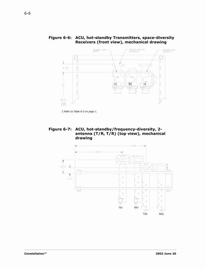
6-6
Figure 6-6: ACU, hot-standby Transmitters, space-diversity Receivers (front view), mechanical drawing
Figure 6-7: ACU, hot-standby/frequency-diversity, 2-antenna (T/R, T/R) (top view), mechanical drawing
1 Refer to Table 6-2 on page 1.
TX1 RX1
TX2 RX2
Constellation™ 2002 June 20

Antenna Coupling Unit (ACU) 6-7
AN
TEN
NA
C
OU
PLIN
G U
NIT
(A
CU
)
Figure 6-8: ACU, hot-standby/frequency-diversity 2-antenna (T/R, T/R) (front view), mechanical drawing
1 Refer to Table 6-2 on page 1.
Harris Corporation Constellation™

6-8
Figure 6-9: ACU, repeater/dual terminal, mechanical drawing
Table 6-4: X dimension from floor, ACU, repeater/dual terminal
ACU frequency (GHz) X dimension (inches)
6 80.24
7/8 79.61
11 79.25
See Table 6-4
See Table 6-5
Constellation™ 2002 June 20

Antenna Coupling Unit (ACU) 6-9
AN
TEN
NA
C
OU
PLIN
G U
NIT
(A
CU
)
ACU Port Configurations
Table 6-5: ACU port configurations
Available ACU Configuration Port 1 Port 2 Port 3
NP (Tx/Rx) TX/RX
NP SD (Tx/Rx, Rx) TX/RX RX
HS (Tx/Rx) TX/RX
HS SD (Tx/Rx, Rx) TX/RX RX
HS, 2 antennas (Tx/Tx, Rx/Rx) TX/TX RX/RX
HS/FD, 2 antennas (Tx/Rx, Tx/Rx) TX/RX TX/RX
FD, 1 antenna (Tx/Tx/Rx/Rx) TX/TX/RX/RX
FD, 2 antennas (Tx/Tx, Rx/Rx) TX/TX RX/RX
NP, 2 antennas (Tx, Rx) TX RX
HS SD, 3 antennas (Tx, Rx, Rx) TX RX RX
NP SD, 3 antennas (Tx, Rx, Rx) TX RX RX
Harris Corporation Constellation™

6-10
Constellation™ 2002 June 20

PER
FO
RM
AN
CE
CU
RV
ES
C H A P T E R
7PERFORMANCE CURVES
Performance Curves
Performance curves provide important parameters (hop distance, channel spacing, and so forth) required for designing a communications system. The curves in this chapter include the following:
1. Typical threshold-to-interference (T/I) curve (6 GHz and 7/8 GHz, 8 DS1)
2. Typical threshold-to-interference (T/I) curve (10/11 GHz, 8 DS1)
3. Typical threshold-to-interference (T/I) curve (6 GHz and 7/8 GHz, 16 DS1)
4. Typical threshold-to-interference (T/I) curve (10/11 GHz, 16 DS1)
5. Typical threshold-to-interference (T/I) curve (6 GHz and 7/8 GHz, 28 DS1/DS3)
6. Typical threshold-to-interference (T/I) curve (10/11 GHz, 28 DS1/DS3)
7. Typical threshold-to-interference (T/I) curve (6, 7/8, 10/11 GHz, 155 Mbit/s, 128 TCM)
8. Typical BER versus C/N curve (8 DS1)
9. Typical BER versus C/N curve (16 DS1)
10. Typical BER versus C/N curve (28 DS1/DS3)
11. Typical BER versus C/N curve (Constellation 155)
12. Typical BER versus RSL curve
13. Typical DS1 jitter transfer curve
14. Typical DS1 input jitter tolerance curve
15. Typical DS3 jitter transfer curve
16. Typical DS3 input jitter tolerance curve
Harris Corporation Constellation™

7-2
Threshold-to-Interference (T/I) Ratios
Overview
The T/I curve shows the strength of interference and the frequency away from the carrier required to degrade the 10-6 BER (bit error ratio) state threshold and the 10-3 BER dynamic/outage thresholds by 1 dB. Measurements were made by fading the wanted received signal level (RSL) until the 10-6 BER point is found (T). A modulated interfering signal is then added until the 10-6 BER point is degraded by 1 dB (I). The measurement is also made with a CW interfering signal which emulates an analog radio FM emission. The ratio is the T/I. The T/I curve is used for choosing radio frequency assignments and to find the fade margin in congested areas. T/I curves plotting allowable T/I versus frequency offset of the interfering signal must be on file with the frequency search companies and are therefore available for all Harris digital microwave radios.
Example: if 10-6 BER threshold is -80 dBm and T/I is 30 dB, then the allowable interference level at threshold is -80 dBm minus 30 dB = -110 dBm.
Constellation™ 2002 June 20

Performance Curves 7-3
PER
FO
RM
AN
CE
CU
RV
ES
Like Signal T/I Ratio
Table 7-1: Like signal T/I for 6 and 7/8 GHz
Capacity Co-channel Adjacent Channel
Two Times Adjacent Channel
T/I (dB) T/I (dB) T/I (dB)
8 DS1 25 -12 - 40
16 DS1 33 - 4 -32
28 DS1/DS3 29 -5 -38
OC-33 x DS3
33 - 4 -32
Table 7-2: Like signal T/I for 10/11 GHz
Capacity Co-channel Adjacent Channel
Two Times Adjacent Channel
T/I (dB) T/I (dB) T/I (dB)
8 DS1 25 -12 -37
16 DS1 33 - 4 -32
28 DS1/DS3 29 -5 -28
OC-33 x DS3
33 - 4 -32
Harris Corporation Constellation™

7-4
T/I Curves
Figure 7-1: Typical threshold-to-interference (T/I) curve (6 GHz and 7/8 GHz, 8 DS1)
-10 -9 -8 -7 -6 -5 -4 -3 -2 -1 0 1 2 3 4 5 6 7 8 9 10-45
-40
-35
-30
-25
-20
-15
-10
-5
0
5
10
15
20
Radio:
Capacity:
Frequency Band:
8 DS1
5850 - 8500 MHz
KEY:Constellation
T/I
(d
B)
Interference Frequency Offset (MHz)
Date: 8/7/2000
Like Interferer
Analog (CW) Interferer
Constellation™ 2002 June 20
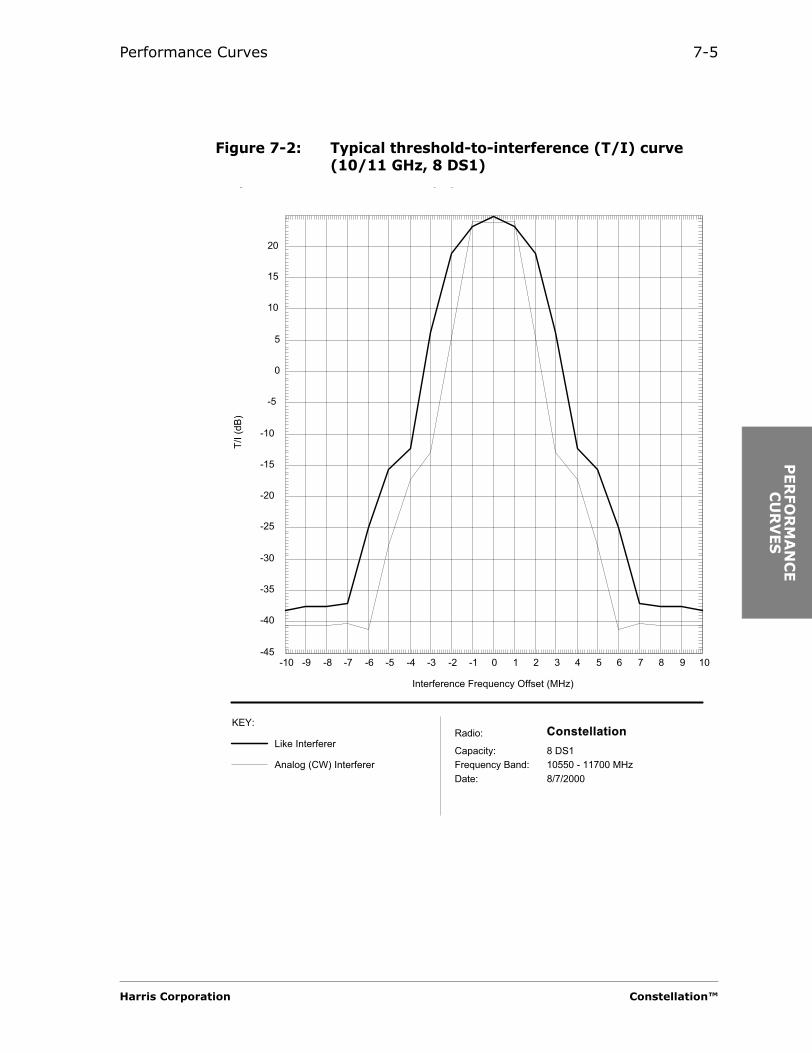
Performance Curves 7-5
PER
FO
RM
AN
CE
CU
RV
ES
Figure 7-2: Typical threshold-to-interference (T/I) curve (10/11 GHz, 8 DS1)
-10 -9 -8 -7 -6 -5 -4 -3 -2 -1 0 1 2 3 4 5 6 7 8 9 10-45
-40
-35
-30
-25
-20
-15
-10
-5
0
5
10
15
20
Radio:
Capacity:
Frequency Band:
8 DS1
10550 - 11700 MHz
KEY:Constellation
y ( )
T/I
(d
B)
Interference Frequency Offset (MHz)
Date: 8/7/2000
Like Interferer
Analog (CW) Interferer
Harris Corporation Constellation™

7-6
Figure 7-3: Typical threshold-to-interference (T/I) curve (6 GHz and 7/8 GHz, 16 DS1)
-10 -9 -8 -7 -6 -5 -4 -3 -2 -1 0 1 2 3 4 5 6 7 8 9 10-35
-30
-25
-20
-15
-10
-5
0
5
10
15
20
25
30
Radio:
Capacity:
Frequency Band:
16 DS1
5850 - 8500 MHz
KEY:Constellation
T/I
(d
B)
Interference Frequency Offset (MHz)
Date: 8/7/2000
Like Interferer
Analog (CW) Interferer
Constellation™ 2002 June 20

Performance Curves 7-7
PER
FO
RM
AN
CE
CU
RV
ES
Figure 7-4: Typical threshold-to-interference (T/I) curve (10/11 GHz, 16 DS1)
-10 -9 -8 -7 -6 -5 -4 -3 -2 -1 0 1 2 3 4 5 6 7 8 9 10-35
-30
-25
-20
-15
-10
-5
0
5
10
15
20
25
30
Radio:
Capacity:
Frequency Band:
16 DS1
10550 - 11700 MHz
KEY:Constellation
T/I
(d
B)
Interference Frequency Offset (MHz)
Date: 8/7/2000
Like Interferer
Analog (CW) Interferer
Harris Corporation Constellation™

7-8
Figure 7-5: Typical threshold-to-interference (T/I) curve (6 GHz and 7/8 GHz, 28 DS1/DS3)
-20 -18 -16 -14 -12 -10 -8 -6 -4 -2 0 2 4 6 8 10 12 14 16 18 20-50
-45
-40
-35
-30
-25
-20
-15
-10
-5
0
5
10
15
20
25
30
Radio:
Capacity:
Frequency Band:
28 DS1
5850 - 8500 MHz
KEY:Constellation
T/I
(d
B)
Interference Frequency Offset (MHz)
Date: 8/7/2000
Like Interferer
Analog (CW) Interferer
Constellation™ 2002 June 20
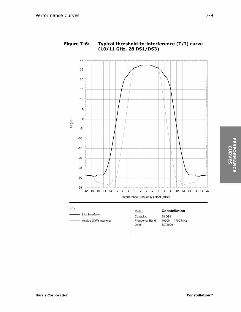
Performance Curves 7-9
PER
FO
RM
AN
CE
CU
RV
ES
Figure 7-6: Typical threshold-to-interference (T/I) curve (10/11 GHz, 28 DS1/DS3)
-20 -18 -16 -14 -12 -10 -8 -6 -4 -2 0 2 4 6 8 10 12 14 16 18 20-35
-30
-25
-20
-15
-10
-5
0
5
10
15
20
25
30
Radio:
Capacity:
Frequency Band:
28 DS1
10700 - 11700 MHz
KEY:Constellation
T/I
(d
B)
Interference Frequency Offset (MHz)
Date: 8/7/2000
Like Interferer
Analog (CW) Interferer
Harris Corporation Constellation™

7-10
Figure 7-7: Typical threshold-to-interference (T/I) curve (6, 7/8, 10/11 GHz, 155 Mbit/s, 128 TCM)
Constellation™ 2002 June 20

Performance Curves 7-11
PER
FO
RM
AN
CE
CU
RV
ES
Receiver Signal-to-Noise Characteristics
BER versus C/N Curve
The Receiver C/N curve indicates how signal to noise affects the BER.
Figure 7-8: Typical BER versus C/N curve (8 DS1)
16 17 18 19 20 21 22 23 2410
-10
10-9
10-8
10-7
10-6
10-5
10-4
10-3
10-2
Radio:
Capacity:
Frequency Band:
8 DS1/STM-0
5850 - 11700 MHz
KEY:Constellation
Bit E
rro
r R
ate
C/N (dB)
Date: 10/6/99
BER vs. C/N
Harris Corporation Constellation™
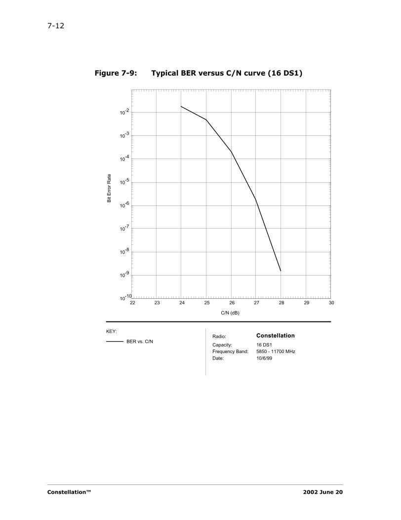
7-12
Figure 7-9: Typical BER versus C/N curve (16 DS1)
22 23 24 25 26 27 28 29 3010
-10
10-9
10-8
10-7
10-6
10-5
10-4
10-3
10-2
Radio:
Capacity:
Frequency Band:
16 DS1/STS-1
5850 - 11700 MHz
KEY:Constellation
Bit E
rro
r R
ate
C/N (dB)
Date: 10/6/99
BER vs. C/N
Constellation™ 2002 June 20

Performance Curves 7-13
PER
FO
RM
AN
CE
CU
RV
ES
Figure 7-10: Typical BER versus C/N curve (28 DS1/DS3)
20 21 22 23 24 25 2610
-10
10-9
10-8
10-7
10-6
10-5
10-4
10-3
10-2
Radio:
Capacity:
Frequency Band:
28 DS1/DS3
5850 - 11700 MHz
KEY:Constellation
Bit E
rror
Rate
C/N (dB)
Date: 10/6/99
BER vs. C/N
Harris Corporation Constellation™

7-14
Figure 7-11: Typical BER versus C/N curve (Constellation 155)
1.00E-10
1.00E-09
1.00E-08
1.00E-07
1.00E-06
1.00E-05
1.00E-04
1.00E-03
23 23.5 24 24.5 25 25.5
C/N (dB)
BER Series1
Constellation™ 2002 June 20

Performance Curves 7-15
PER
FO
RM
AN
CE
CU
RV
ES
BER versus RSL Dynamic Range
The increase of BER as the result of a faded RSL indicates the sensitivity of the Receiver. The curve includes the received signal overload characteristics.
The dynamic range of the Receiver is the range from the low RSL to the high RSL at 10-6 BER or other BER (10-3 outage, 10-13 error-free, and so forth).
Figure 7-12: Typical BER versus RSL curve
-80 -75 -70 -65 -60 -55 -50 -45 -40 -35 -30 -25 -20 -15 -1010
-13
10-12
10-11
10-10
10-9
10-8
10-7
10-6
10-5
10-4
10-3
10-2
Radio:
Capacity:
Frequency Band:
16 DS1
5850 - 6875 MHz
KEY:Constellation
Bit E
rror
Rate
Receive Signal Level (dBm)
Date: 12/7/99
BER vs. RSL
Harris Corporation Constellation™

7-16
Jitter Characteristics
This set of curves contains two types of jitter curves: a curve of the jitter transfer function and a curve of the jitter tolerance. The curve of the jitter transfer function shows how jitter at different frequencies is attenuated in the radio and is shown with ITU-T G.958 mask. The jitter tolerance curve shows how much jitter at various frequencies the radio will tolerate at its inputs before errors occur as specified in ITU-T G.958.
Figure 7-13: Typical DS1 jitter transfer curve
Figure 7-14: Typical DS1 input jitter tolerance curve
0.10
10 9650
slope = -20 dB/decade
Jitter Frequency (Hz)
Jitte
r Gai
n (d
B)
AcceptableRange
10
0.3
10 192.9 6430 40000
AcceptableRange
slope = -20 dB/decade
Jitter Frequency (Hz)
Inpu
t Jitt
er A
mpl
itude
(UI p
p)
Constellation™ 2002 June 20

Performance Curves 7-17
PER
FO
RM
AN
CE
CU
RV
ES
Figure 7-15: Typical DS3 jitter transfer curve
Figure 7-16: Typical DS3 input jitter tolerance curve
0.10
10 59600
slope = -20 dB/decade
Jitter Frequency (Hz)
Jitte
r Gai
n (d
B)
AcceptableRange
10
0.3
10 669 22300 300000
AcceptableRange
slope = -20 dB/decade
Jitter Frequency (Hz)
Inpu
t Jitt
er A
mpl
itude
(UI p
p)
Harris Corporation Constellation™

7-18
Constellation™ 2002 June 20
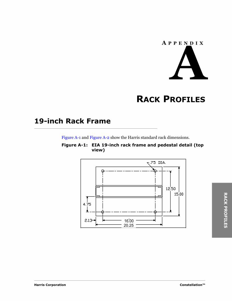
RA
CK
PR
OFILE
S
A P P E N D I X
ARACK PROFILES
19-inch Rack Frame
Figure A-1 and Figure A-2 show the Harris standard rack dimensions.
Figure A-1: EIA 19-inch rack frame and pedestal detail (top view)
16.0020.25
Harris Corporation Constellation™

A-2
Figure A-2: EIA 19-inch rack frame and pedestal detail
Front View Side View
Constellation™ 2002 June 20

GLO
SS
AR
A P P E N D I X
BGLOSSARY
A
ACU. Antenna Coupling Unit.
AGC. Automatic Gain Control; automatic gain adjustment of a varying input signal level to produce a constant output signal level.
AIS. Alarm Indication Signal.
AMI. Alternate Mark Inversion.
AMSL. Above Mean Sea Level.
ANSI. American National Standards Institute.
ATDE. Adaptive Time Domain Equalizer.
ATPC. Automatic Transmitter Power Control.
AUX. Auxiliary port.
B
B8ZS. Bipolar with Eight Zero Substitution.
baseband. A frequency band occupied by a modulating information signal.
Bellcore. Bell Communications Research, Inc. (source of telephony standards in the U.S.A.).
BER. Bit Error Ratio.
BERT. Bit Error Ratio Tester.
C
CAN. Controller Area Network. An interface standard (ISO 11898) for interconnecting microcontrollers.
Harris Corporation Constellation™
Y

B-2
CFM. Composite Fade Margin.
CGA. Carrier Group Alarm.
CPE. Customer Premises Equipment.
CW. Continuous Wave.
D
DACS. Digital Access and Cross-connect System.
DADE. Differential Absolute Delay Equalization. A method for aligning, in time, two identical data streams that are traveling through channels of differing length (time).
DFM. Dispersive Fade Margin.
D connectors, subminiature. The size of the subminiature D connector is specified by the standard shell size and the number of connectors. For example, a 15-pin connector is referred to as a DA-15. See the following table.
DCS. Digital Cross-connect System.
DTMF. Dual-Tone MultiFrequency.
E
EFS. Error-Free Seconds.
EIA. Electronic Industries Association.
EMI. Electro-Magnetic Interference.
ERP. Effective Radiated Power.
ES. Errored Seconds.
ETSI. European Telecommunications Standards Institute.
Standard Shell Size
No. of Connectors
E 9
A 15
B 25
C 37
D 50
Constellation™ 2002 June 20
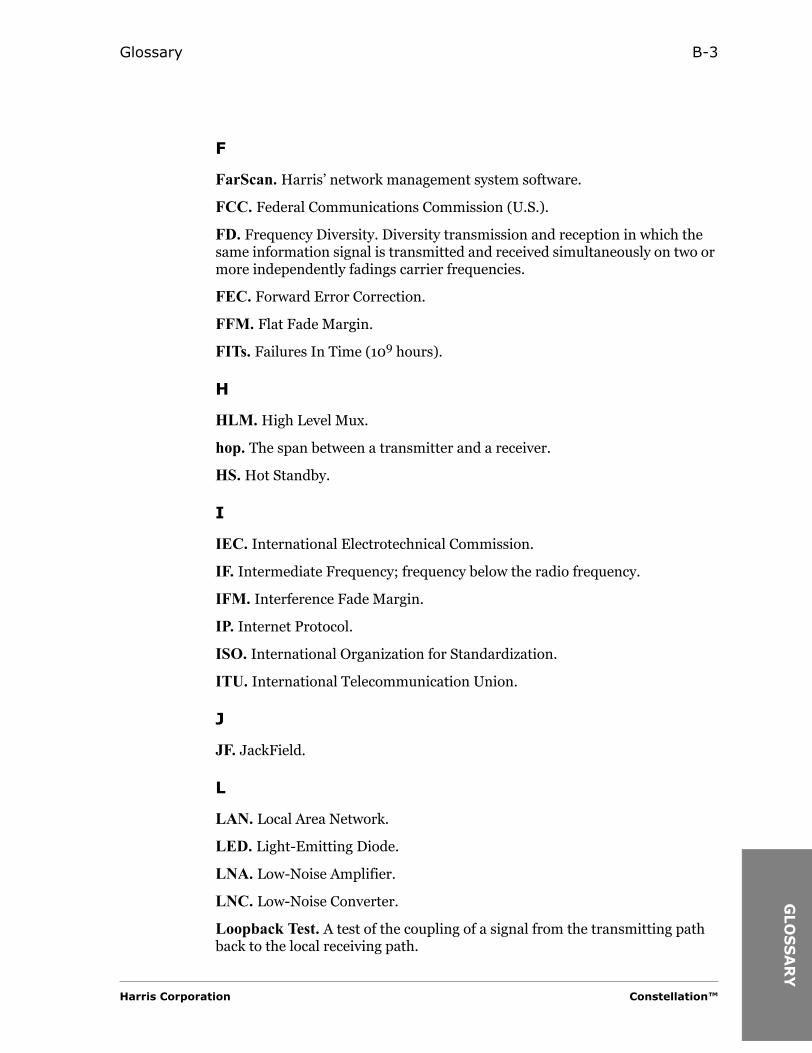
Glossary B-3
GLO
SS
AR
F
FarScan. Harris’ network management system software.
FCC. Federal Communications Commission (U.S.).
FD. Frequency Diversity. Diversity transmission and reception in which the same information signal is transmitted and received simultaneously on two or more independently fadings carrier frequencies.
FEC. Forward Error Correction.
FFM. Flat Fade Margin.
FITs. Failures In Time (109 hours).
H
HLM. High Level Mux.
hop. The span between a transmitter and a receiver.
HS. Hot Standby.
I
IEC. International Electrotechnical Commission.
IF. Intermediate Frequency; frequency below the radio frequency.
IFM. Interference Fade Margin.
IP. Internet Protocol.
ISO. International Organization for Standardization.
ITU. International Telecommunication Union.
J
JF. JackField.
L
LAN. Local Area Network.
LED. Light-Emitting Diode.
LNA. Low-Noise Amplifier.
LNC. Low-Noise Converter.
Loopback Test. A test of the coupling of a signal from the transmitting path back to the local receiving path.
Harris Corporation Constellation™
Y

B-4
LOS. Loss Of Signal.
M
M12. A multiplexing method that transforms between 1 DS1 up to 4 DS1 input/outputs and a T2 output/output.
M2X. A multiplexing method that transforms between 1 T2 up to 7 T2 input/outputs and a T3 output/output.
MCD. Microwave Communications Division, formerly Farinon Division.
MHSB. Monitored Hot StandBy.
MIB. Management Information Base.
MTBF. Mean Time Between Failures.
MTBO. Mean Time Between Outages.
MTR. Mean Time to Restore the circuit after failure.
MTTR. Mean Time To Repair.
MUX. MUltipleXer.
N
NMS. Network Management System.
Noise Figure. The ratio of the output noise power to the portion of the output noise power stemming from thermal noise at the input at standard noise temperature.
NP. NonProtected.
NRZ. NonReturn to Zero (coding).
NTIA. National Telecommunications and Information Administration (U.S.A.)
P
PA. Power Amplifier.
PBX. Private Branch Exchange.
PCB. Printed Circuit Board.
PCM. Pulse Code Modulation.
Constellation™ 2002 June 20

Glossary B-5
GLO
SS
AR
Q
QAM. Quadrature Amplitude Modulation. Quadrature modulation in which two carriers are amplitude-modulated.
R
RF. Radio Frequency.
RFI. Radio Frequency Interference.
RIP. Routing for Internet Protocol.
RMS. Root Mean Square.
RSL. Received Signal Level.
RTU. Remote Terminal Unit.
RX. Receiver.
S
SAI. System Application Information.
SCAN. System Control And Alarm Network. Harris’ proprietary standard for sending alarm/status/control messages over a serial port.
SD. Space Diversity. Pertaining to signal transmission and reception in which two or more separate and independent propagation media or paths are used for transmitting the same information.
SES. Severely Errored-Seconds.
SLVA. Successive Log Video Amplifier.
SNMP. Simple Network Management Protocol.
SNR. Signal-to-Noise Ratio.
SPU. Signal Processing Unit.
SPUR. Extended SCAN port. A communications channel branching of from the trunk and generally carrying less traffic than the trunk.
ST. Split Transmitters.
T
TCM. Trellis-Coded Modulation.
TFM. Thermal Fade Margin.
T/I. Threshold-to-Interference ratio.
Harris Corporation Constellation™
Y
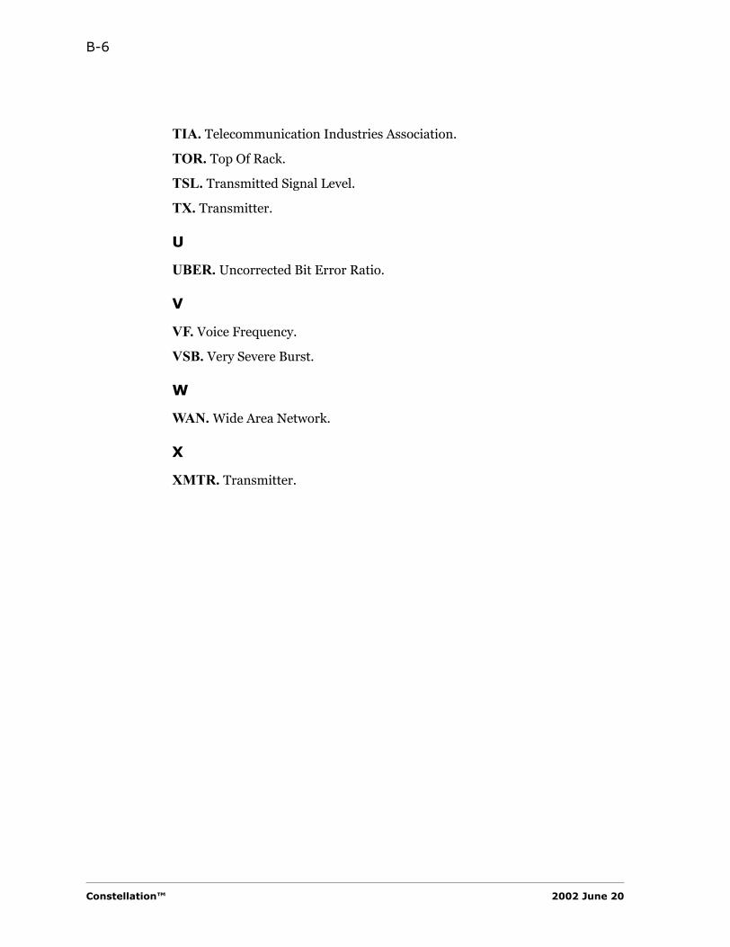
B-6
TIA. Telecommunication Industries Association.
TOR. Top Of Rack.
TSL. Transmitted Signal Level.
TX. Transmitter.
U
UBER. Uncorrected Bit Error Ratio.
V
VF. Voice Frequency.
VSB. Very Severe Burst.
W
WAN. Wide Area Network.
X
XMTR. Transmitter.
Constellation™ 2002 June 20

IND
EX
A P P E N D I X
IINDEX
Numerics1+1 frequency spacing 2-161+1 intermodulation products 2-161+1 switching times 4-141+1 Transmitter and Receiver switching 4-
1210Base-T 4-14, 5-83x3DS3 system
add-drop mode 3-23xDS3 compatibility 3-2
AACU. See Antenna Coupling Unit.add-drop in repeater configuration 3-1add-drop mode
3xDS3 system 3-2address, DTMF receiver decoder 5-5AIS 4-15alarm
RSL 4-13uncorrected BER 4-13
alarm inputs 4-15alarm list for relay output 4-16alarms monitoring 3-3aluminum rack 4-17ambient temperature 4-17ANSI 4-10antenna
feeder 2-16
Harris Corporation
Antenna Coupling Unitavailable configurations 6-2mechanical drawings 6-3port configurations 6-9specifications 6-1
asynchronous start-stop signals 5-5ATDE 1-1ATPC 1-1
Bbattery noise level 4-2Bellcore 4-10, 4-17BER
residual, Receiver 4-8BER alarm, uncorrected 4-13BER versus C/N curve 7-11BER versus RSL dynamic range curve 7-15bridged data ports 5-5
CC/N curve, Receiver 7-11capacity
high 3-2narrow/medium 3-1
CAU 5-7channel assignments 2-3code
FEC 4-12Reed-Solomon 4-12
compatibility, 3xDS3 and HLM-155 3-2configuring
Service Channel 3-10
Constellation™

I-2
Constellation Radio 3-1platform 3-1
Constellation radiodimensions 4-18features 1-1interconnection 5-1ports 5-7VF ports 5-2weights 4-18
Constellation radios 1-1control outputs 4-15cost-effective communication solutions 1-2craft interface tool 3-3curves
performance 7-1
DDA-15 5-3data orderwire interface 5-5data ports
bridged 5-5RS-232 5-5
DB-25 5-2, 5-7DC-37 5-2DE-9 5-2, 5-7degradation, threshold 2-16diagnosing through the Keypad 3-3dimensions
Constellation 4-18dispersive fade margin, Receiver 4-9dry relay contacts 4-16DS3-to-DS3 interface, number of hops 3-2DTMF receiver decoder 5-5DVA 5-7DVS II
orderwire 5-5orderwire interconnection 5-2
Constellation™
dynamic range, Receiver 7-15
Eearthquake standards 4-17electromagnetic emissions 4-17emission limitations 4-7environmental specifications 4-17equipment failure 4-15equipment transmission delay time 4-11Errored Seconds alarm 4-16errorless receiver switching 1-1Ethernet port
Constellation 4-14, 5-8ETS 300 826 4-17External Alarm/Control connector 4-16
FFarScan 1-2, 3-3
connection 4-14FCC 4-7, 4-17FEC 1-1
code 4-12feeder, antenna 2-16flange specifications 6-1forward error correction. See FEC.four-wire VF orderwire interface 5-4four-wire VF specifications 5-4frequency bands 2-1frequency spacing
1+1 2-16frequency stability
Receiver 4-8Transmitter 4-7
2002 June 20

Index I-3
IND
EX
full duplex 5-5fuse panel 4-2
GGlobeStar 5-7glossary B-1
Hhalf-duplex communications 5-5high capacity radio 3-2High Level Mux
repeater configuration 3-10source timing mode 3-10terminal configuration 3-10through timing mode 3-10
HLM. See High Level Mux.HLM-155 compatibility 3-2hops, DS3-to-DS3 3-2hot-standby
protection 4-12humidity 4-17
Iimage rejection, Receiver 4-8input noise level 4-2interconnection
SCAN and Constellation 5-7Service Channel and Constellation 5-1
interfacesnetwork management 4-14supervisory 4-14
intermediate frequency signal 4-12intermodulation frequency products 2-16intermodulation products, 1+1 2-16ITU-T 4-10
Jjitter
curves 7-16tolerance 7-16transfer function 7-16tributary 4-10
Harris Corporation
jitter accumulation, minimizing 3-10
KKeypad 3-3, 4-16, 5-4, 5-5Keypad port 4-14
LLED indicators 4-15liability 1-2like signal T/I 7-3Local Off Hook 3-10LOS
alarm 4-16loss of signal to multiplexer 4-15
MM12 Unit
power consumption 4-1restoration of data 4-15
Major Alarm 4-16Manual Control, configurable 4-16manual switch-over 4-13medium capacity radio 3-1MegaStar 5-2MicroStar 5-2, 5-7Minor Alarm 4-16minor alarm
locking of RF modules 4-13modulation characteristics 4-11multiplexer
configuration 3-4loss of signal 4-15
Nnarrow/medium capacity radio 3-1NetBoss 3-3network management 3-3network management interfaces 4-14noise level
battery 4-2input 4-2
Constellation™
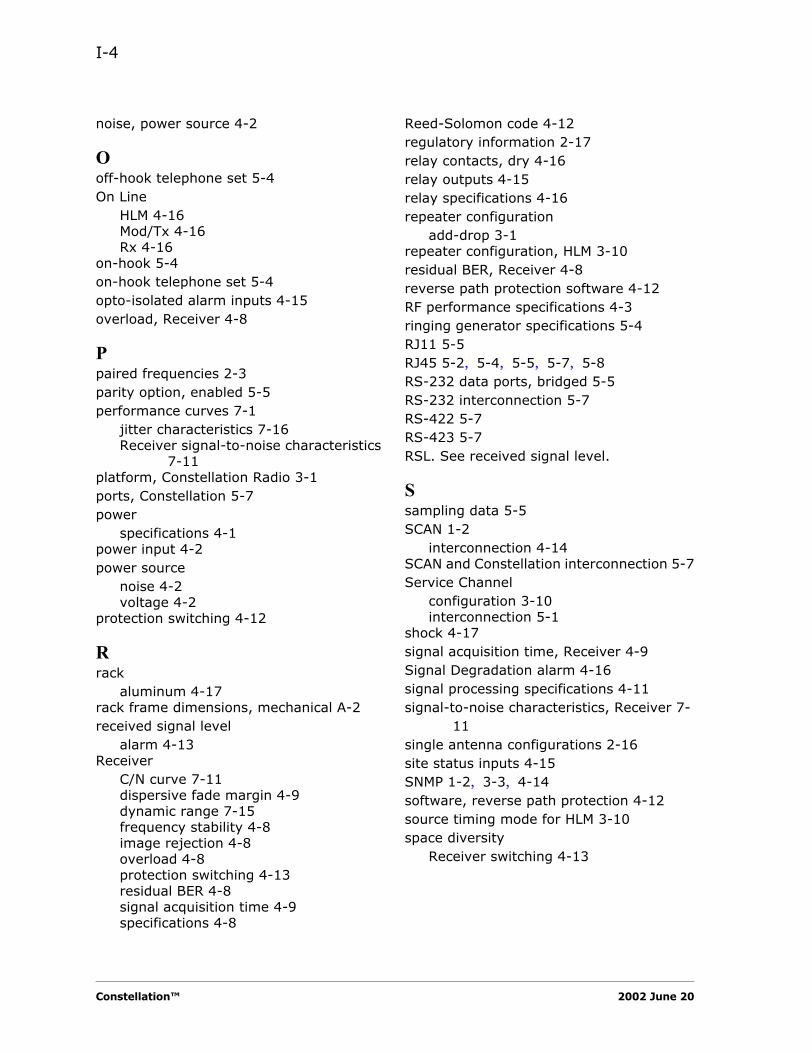
I-4
noise, power source 4-2
Ooff-hook telephone set 5-4On Line
HLM 4-16Mod/Tx 4-16Rx 4-16
on-hook 5-4on-hook telephone set 5-4opto-isolated alarm inputs 4-15overload, Receiver 4-8
Ppaired frequencies 2-3parity option, enabled 5-5performance curves 7-1
jitter characteristics 7-16Receiver signal-to-noise characteristics
7-11platform, Constellation Radio 3-1ports, Constellation 5-7power
specifications 4-1power input 4-2power source
noise 4-2voltage 4-2
protection switching 4-12
Rrack
aluminum 4-17rack frame dimensions, mechanical A-2received signal level
alarm 4-13Receiver
C/N curve 7-11dispersive fade margin 4-9dynamic range 7-15frequency stability 4-8image rejection 4-8overload 4-8protection switching 4-13residual BER 4-8signal acquisition time 4-9specifications 4-8
Constellation™
Reed-Solomon code 4-12regulatory information 2-17relay contacts, dry 4-16relay outputs 4-15relay specifications 4-16repeater configuration
add-drop 3-1repeater configuration, HLM 3-10residual BER, Receiver 4-8reverse path protection software 4-12RF performance specifications 4-3ringing generator specifications 5-4RJ11 5-5RJ45 5-2, 5-4, 5-5, 5-7, 5-8RS-232 data ports, bridged 5-5RS-232 interconnection 5-7RS-422 5-7RS-423 5-7RSL. See received signal level.
Ssampling data 5-5SCAN 1-2
interconnection 4-14SCAN and Constellation interconnection 5-7Service Channel
configuration 3-10interconnection 5-1
shock 4-17signal acquisition time, Receiver 4-9Signal Degradation alarm 4-16signal processing specifications 4-11signal-to-noise characteristics, Receiver 7-
11single antenna configurations 2-16site status inputs 4-15SNMP 1-2, 3-3, 4-14software, reverse path protection 4-12source timing mode for HLM 3-10space diversity
Receiver switching 4-13
2002 June 20

Index I-5
IND
EX
spacer adapter height 6-1specification compliance, tributary 4-10specifications
4-wire VF ports 5-4ACU 6-1environment 4-17flange 6-1four-wire VF 5-4power 4-1relay 4-16RF performance 4-3ringing generator 5-4technical 4-1top of rack antenna port 4-3Transmitter 4-7
start-stop, asynchronous 5-5StarView 3-3, 5-8supervisory interfaces 4-14switching
protection 4-12times 4-14
Sync Loss A alarm 4-16Sync Loss B alarm 4-16synchronization configuration 3-10
TT/I
curves 7-4T/I curve 7-2T/I like signal 7-3technical specifications 4-1
Receiver 4-8signal processing 4-11Tributary Interface 4-10
telephone set 5-4off-hook 5-4
temperature, ambient 4-17terminal configuration, HLM cards 3-10threshold
degradation 2-16
Harris Corporation
threshold-to-interference (T/I) ratio 7-2through timing mode for HLM 3-10times, 1+1 switching 4-14top of rack antenna port specifications 4-3transmission delay per hop 4-11Transmitter
frequency stability 4-7protection switching 4-12specifications 4-7unwanted emissions 4-7
Tributary Interfacetechnical specifications 4-10
tributary jitter 4-10tributary signal characteristics 4-10tributary specification compliance 4-10two-wire VF orderwire interface 5-5
Uuncorrected BER alarm 4-13unwanted emissions, Transmitter 4-7upgradability 3-2
VVF orderwire interface
2-wire 5-54-wire 5-4
VF ports, Constellation 5-2vibration 4-17voltage
power source 4-2VT100-compatible terminal 3-3
Wwaveguide flange specifications 6-1weights, Constellation 4-18
Zzone 2 4-17zone 4 4-17
Constellation™

I-6
Constellation™
2002 June 20

SAI-112874-E04
Microwave Communications Division 350 Twin Dolphin Drive Redwood Shores, CA USA 94065-1421
www.harris.com
USA 1-800-227-8332 1-650-594-3800
next level solutions