Systems & Devices Part 1
27
Systems & Devices – Part 1 Alexander Nelson February 1, 2022 University of Arkansas - Department of Computer Science and Computer Engineering
Transcript of Systems & Devices Part 1
Systems & Devices – Part 1
Alexander Nelson
February 1, 2022
University of Arkansas - Department of Computer Science and Computer Engineering

What composes wearable, ubiquitous, or
invisible systems?
0

Components of Systems
Ubicomp systems are composed of a subset of the following:
• Sensors
• Actuators
• Communications
• Displays
• Storage
• Computation
where the components & scale of each is defined by the application
1

Sensors

Types of Sensors
Many different types of sensors
Wikipedia categorization (summarized):
• Acoustic
• Chemical
• Electric Current
• Environmental
• Proximity
• Inertial
• Optical
• Pressure
• Force
• Thermal
2

Sensor Interfaces
Systems use many interfaces to obtain sensor values
These include:
• Binary Signals
• Analog to Digital
• Parallel Interfaces
• Serial Interfaces (SPI, I2C, UART)
• Pulse Width Modulation
3

Binary Signals
Binary Signals – 0 or 1
Pushbuttons, Threshold values, counts, etc...
P2 is latched periodically
Will be 0 unless switch is engaged
4

Debouncing
Imperfect contact can create “glitches”
Use delays to verify signal is steady
5

Analog vs. Digital
Analog Digital
6

Conversion
To work with sensor data, analog signals must be converted to
digital
Analog to Digital Conversion (A to D)7
Sampling/Conversion
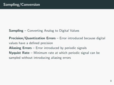
Sampling – Converting Analog to Digital Values
Precision/Quantization Errors – Error introduced because digital
values have a defined precision
Aliasing Errors – Error introduced by periodic signals
Nyquist Rate – Minimum rate at which periodic signal can be
sampled without introducing aliasing errors
8

Aliasing Error
1
1http://www.bb-elec.com/Learning-Center/All-White-Papers/Data-
Aquisition-and-IO/The-Fine-Art-of-Analog-Signal-Sampling.aspx
9

Measurement Circuits
Sensor manufacturers create elements that have a predictable
response to a stimulus
These responses modulate a quantity that can be sampled by a
digital system
Typical quantities:
• Resistance
• Capacitance
• Inductance
10
Analog to Digital – Voltage Divider
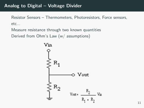
Resistor Sensors – Thermometers, Photoresistors, Force sensors,
etc...
Measure resistance through two known quantities
Derived from Ohm’s Law (w/ assumptions)
11

Analog to Digital – Wheatstone Bridge
Wheatstone Bridge – Voltage Measurement
Can allow differential measurement, non absolute references, and
can be extremely precise
12
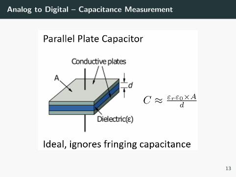
Analog to Digital – Capacitance Measurement
13
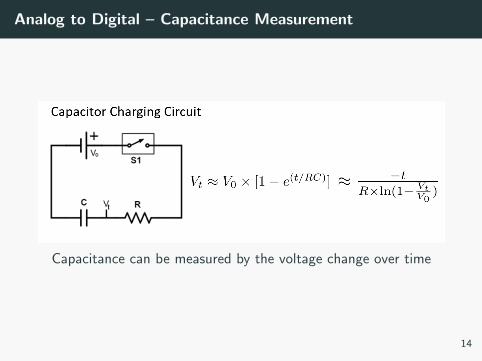
Analog to Digital – Capacitance Measurement
Capacitance can be measured by the voltage change over time
14
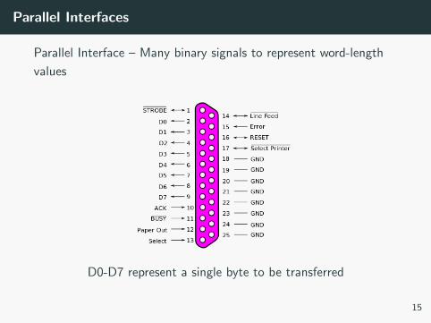
Parallel Interfaces
Parallel Interface – Many binary signals to represent word-length
values
D0-D7 represent a single byte to be transferred
15
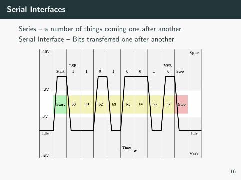
Serial Interfaces
Series – a number of things coming one after another
Serial Interface – Bits transferred one after another
16
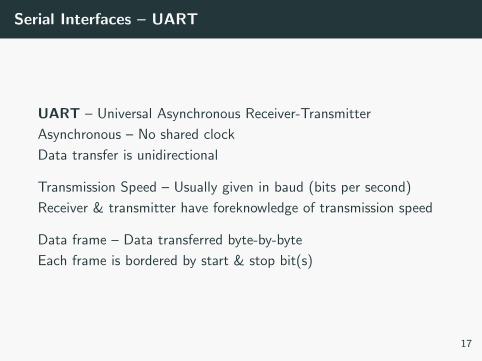
Serial Interfaces – UART
UART – Universal Asynchronous Receiver-Transmitter
Asynchronous – No shared clock
Data transfer is unidirectional
Transmission Speed – Usually given in baud (bits per second)
Receiver & transmitter have foreknowledge of transmission speed
Data frame – Data transferred byte-by-byte
Each frame is bordered by start & stop bit(s)
17

Serial Interfaces – SPI
SPI – Serial Peripheral Interface
Synchronous unidirectional master–slave data transfer
Master device configures clock, clock polarity, and when
communication occurs
Data frame – Frame started by a logic 0 on the Source Select line
Determines which slave device is to listen
Data is transferred bit-by-bit, latched at either rising or falling
edges
18
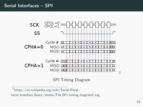
Serial Interfaces – SPI
2
SPI Timing Diagram
2https://en.wikipedia.org/wiki/Serial Perip-
heral Interface Bus#/media/File:SPI timing diagram2.svg
19
Serial Interfaces – I2C
I2C – Inter-Integrated Circuit (I-squared-C)
Address-based 2-wire communication interface
20

Serial Interfaces – I2C – Data Transfer
1. Data transfer initiated(S) – SDA pulled low, SCL stays high.
2. SCL is pulled low, and SDA sets the first data bit level while
keeping SCL low (during blue bar time).
3. The data are sampled (received) when SCL rises for the first
bit (B1). For a bit to be valid, SDA must not change between
a rising edge of SCL and the subsequent falling edge.
4. This process repeats, SDA transitioning while SCL is low, and
the data being read while SCL is high (B2, ...Bn).
5. The final bit is followed by a clock pulse, during which SDA is
pulled low in preparation for the stop bit.
6. Stop bit (P) signaled when SCL rises, followed by SDA rising 21

Serial Interfaces – I2C – Addresses
I2C has only 2 data lines
Uses addresses to specify which chip listens
Address is 7 bits followed by a write bit
Write bit specifies if action is to read or write at register address
22
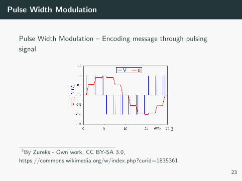
Pulse Width Modulation
Pulse Width Modulation – Encoding message through pulsing
signal
3
3By Zureks - Own work, CC BY-SA 3.0,
https://commons.wikimedia.org/w/index.php?curid=1835361
23

Pulse Width Modulation
Applications of PWM:
• Sensor output
• Servo Input
• LED dimming
• Power Delivery
24